JP2005294878A - Video display device for vehicle environment monitoring unit - Google Patents
Video display device for vehicle environment monitoring unit Download PDFInfo
- Publication number
- JP2005294878A JP2005294878A JP2004085973A JP2004085973A JP2005294878A JP 2005294878 A JP2005294878 A JP 2005294878A JP 2004085973 A JP2004085973 A JP 2004085973A JP 2004085973 A JP2004085973 A JP 2004085973A JP 2005294878 A JP2005294878 A JP 2005294878A
- Authority
- JP
- Japan
- Prior art keywords
- display device
- video image
- image display
- image
- vehicle
- Prior art date
- Legal status (The legal status is an assumption and is not a legal conclusion. Google has not performed a legal analysis and makes no representation as to the accuracy of the status listed.)
- Pending
Links
- 238000012544 monitoring process Methods 0.000 title claims abstract description 24
- 230000007257 malfunction Effects 0.000 claims abstract description 20
- 238000001454 recorded image Methods 0.000 claims abstract description 20
- 238000012545 processing Methods 0.000 claims abstract description 10
- 238000012432 intermediate storage Methods 0.000 claims description 10
- 230000003287 optical effect Effects 0.000 claims description 10
- 230000007613 environmental effect Effects 0.000 claims description 5
- 230000004297 night vision Effects 0.000 claims description 5
- 230000006870 function Effects 0.000 abstract description 6
- 238000012360 testing method Methods 0.000 abstract description 5
- 230000003068 static effect Effects 0.000 abstract 1
- 238000003860 storage Methods 0.000 description 6
- 238000000034 method Methods 0.000 description 4
- 230000008859 change Effects 0.000 description 3
- 238000011156 evaluation Methods 0.000 description 3
- 238000012937 correction Methods 0.000 description 2
- 238000001514 detection method Methods 0.000 description 2
- 238000003672 processing method Methods 0.000 description 2
- 230000004044 response Effects 0.000 description 2
- 230000000007 visual effect Effects 0.000 description 2
- 230000004913 activation Effects 0.000 description 1
- 230000005540 biological transmission Effects 0.000 description 1
- 230000004397 blinking Effects 0.000 description 1
- 230000000052 comparative effect Effects 0.000 description 1
- 230000001419 dependent effect Effects 0.000 description 1
- 238000011161 development Methods 0.000 description 1
- 230000018109 developmental process Effects 0.000 description 1
- 238000010586 diagram Methods 0.000 description 1
- 230000004907 flux Effects 0.000 description 1
- 238000007689 inspection Methods 0.000 description 1
- 238000012986 modification Methods 0.000 description 1
- 230000004048 modification Effects 0.000 description 1
- 230000002265 prevention Effects 0.000 description 1
- 230000008569 process Effects 0.000 description 1
- 238000004092 self-diagnosis Methods 0.000 description 1
- 230000000153 supplemental effect Effects 0.000 description 1
- 238000001429 visible spectrum Methods 0.000 description 1
Images
Classifications
-
- H—ELECTRICITY
- H04—ELECTRIC COMMUNICATION TECHNIQUE
- H04N—PICTORIAL COMMUNICATION, e.g. TELEVISION
- H04N17/00—Diagnosis, testing or measuring for television systems or their details
-
- G—PHYSICS
- G01—MEASURING; TESTING
- G01S—RADIO DIRECTION-FINDING; RADIO NAVIGATION; DETERMINING DISTANCE OR VELOCITY BY USE OF RADIO WAVES; LOCATING OR PRESENCE-DETECTING BY USE OF THE REFLECTION OR RERADIATION OF RADIO WAVES; ANALOGOUS ARRANGEMENTS USING OTHER WAVES
- G01S11/00—Systems for determining distance or velocity not using reflection or reradiation
- G01S11/12—Systems for determining distance or velocity not using reflection or reradiation using electromagnetic waves other than radio waves
-
- B—PERFORMING OPERATIONS; TRANSPORTING
- B60—VEHICLES IN GENERAL
- B60R—VEHICLES, VEHICLE FITTINGS, OR VEHICLE PARTS, NOT OTHERWISE PROVIDED FOR
- B60R2300/00—Details of viewing arrangements using cameras and displays, specially adapted for use in a vehicle
- B60R2300/20—Details of viewing arrangements using cameras and displays, specially adapted for use in a vehicle characterised by the type of display used
- B60R2300/207—Details of viewing arrangements using cameras and displays, specially adapted for use in a vehicle characterised by the type of display used using multi-purpose displays, e.g. camera image and navigation or video on same display
-
- B—PERFORMING OPERATIONS; TRANSPORTING
- B60—VEHICLES IN GENERAL
- B60R—VEHICLES, VEHICLE FITTINGS, OR VEHICLE PARTS, NOT OTHERWISE PROVIDED FOR
- B60R2300/00—Details of viewing arrangements using cameras and displays, specially adapted for use in a vehicle
- B60R2300/30—Details of viewing arrangements using cameras and displays, specially adapted for use in a vehicle characterised by the type of image processing
-
- B—PERFORMING OPERATIONS; TRANSPORTING
- B60—VEHICLES IN GENERAL
- B60R—VEHICLES, VEHICLE FITTINGS, OR VEHICLE PARTS, NOT OTHERWISE PROVIDED FOR
- B60R2300/00—Details of viewing arrangements using cameras and displays, specially adapted for use in a vehicle
- B60R2300/30—Details of viewing arrangements using cameras and displays, specially adapted for use in a vehicle characterised by the type of image processing
- B60R2300/304—Details of viewing arrangements using cameras and displays, specially adapted for use in a vehicle characterised by the type of image processing using merged images, e.g. merging camera image with stored images
- B60R2300/305—Details of viewing arrangements using cameras and displays, specially adapted for use in a vehicle characterised by the type of image processing using merged images, e.g. merging camera image with stored images merging camera image with lines or icons
-
- B—PERFORMING OPERATIONS; TRANSPORTING
- B60—VEHICLES IN GENERAL
- B60R—VEHICLES, VEHICLE FITTINGS, OR VEHICLE PARTS, NOT OTHERWISE PROVIDED FOR
- B60R2300/00—Details of viewing arrangements using cameras and displays, specially adapted for use in a vehicle
- B60R2300/40—Details of viewing arrangements using cameras and displays, specially adapted for use in a vehicle characterised by the details of the power supply or the coupling to vehicle components
- B60R2300/404—Details of viewing arrangements using cameras and displays, specially adapted for use in a vehicle characterised by the details of the power supply or the coupling to vehicle components triggering from stand-by mode to operation mode
-
- B—PERFORMING OPERATIONS; TRANSPORTING
- B60—VEHICLES IN GENERAL
- B60R—VEHICLES, VEHICLE FITTINGS, OR VEHICLE PARTS, NOT OTHERWISE PROVIDED FOR
- B60R2300/00—Details of viewing arrangements using cameras and displays, specially adapted for use in a vehicle
- B60R2300/80—Details of viewing arrangements using cameras and displays, specially adapted for use in a vehicle characterised by the intended use of the viewing arrangement
- B60R2300/8053—Details of viewing arrangements using cameras and displays, specially adapted for use in a vehicle characterised by the intended use of the viewing arrangement for bad weather conditions or night vision
-
- B—PERFORMING OPERATIONS; TRANSPORTING
- B60—VEHICLES IN GENERAL
- B60R—VEHICLES, VEHICLE FITTINGS, OR VEHICLE PARTS, NOT OTHERWISE PROVIDED FOR
- B60R2300/00—Details of viewing arrangements using cameras and displays, specially adapted for use in a vehicle
- B60R2300/80—Details of viewing arrangements using cameras and displays, specially adapted for use in a vehicle characterised by the intended use of the viewing arrangement
- B60R2300/806—Details of viewing arrangements using cameras and displays, specially adapted for use in a vehicle characterised by the intended use of the viewing arrangement for aiding parking
Landscapes
- Engineering & Computer Science (AREA)
- Physics & Mathematics (AREA)
- Health & Medical Sciences (AREA)
- General Physics & Mathematics (AREA)
- Radar, Positioning & Navigation (AREA)
- Remote Sensing (AREA)
- Electromagnetism (AREA)
- Biomedical Technology (AREA)
- General Health & Medical Sciences (AREA)
- Multimedia (AREA)
- Signal Processing (AREA)
- Closed-Circuit Television Systems (AREA)
- Traffic Control Systems (AREA)
Abstract
Description
本発明は、車両環境監視ユニット用のビデオ表示装置に関する。 The present invention relates to a video display device for a vehicle environment monitoring unit.
最新の車両には、車両運転者に対応するよう設計された、様々な運転者支援システムが備えられている。その中でますますその頻度が増しているものに、画像提供環境監視システムがある。自動車の分野においては、例えば、赤外線センサを使用して車両の前方の車両環境が検出される暗視システムがある。検出された環境データは、データ処理ユニットを使用して画像へと処理され、表示装置上に描写され、必要な場合には車両運転者がこの表示装置にアクセスすることができる。 Modern vehicles are equipped with various driver assistance systems designed to accommodate the vehicle driver. Among them, an image providing environment monitoring system is increasing in frequency. In the field of automobiles, for example, there are night vision systems in which the vehicle environment in front of the vehicle is detected using an infrared sensor. The detected environmental data is processed into an image using a data processing unit and rendered on a display device, which can be accessed by the vehicle driver if necessary.
特許文献1では、車両の前方の環境を観測するシステムが記載されている。このシステムの中には、システムに誤動作が生じると、それを特定するマイクロコンピュータが含まれる。誤動作またはエラーの判断は、特に、記録された画像の輝度データの評価に基づく。画像を記録するために2台のカメラが用いられ、それぞれ、車両の前方の環境の1枚の視像(投影像)を記録する。エラー検出の枠組みにおいては、まず、記録された画像データの光強度値が、立体像処理ユニットを使用して計算される。次いで、マイクロコンピュータまたはマイクロプロセッサが、計算された光強度値に基づいて、システムに誤動作が存在するかどうかを判断する。システム不良が生じた場合には、フェイルセーフ防止策がとられる。
特許文献2では、車両カメラ用の画像処理システムが記載されている。車両の環境下に設置された車両の車両カメラにより、個々の画像が撮像され、それからビデオ信号が生成される。画像処理システムは、自己診断ユニットを含む。この自己診断ユニットを使用して、車両カメラの機能が評価される。この評価の枠組みにおいては、2台の車両カメラの個々の画像が、互いに比較される。この比較には画像処理方法が用いられ、この画像処理方法では、オプティカルフローやフラックスなどのプロセスを用いることができる。
特許文献3では、車両用の追跡システムが記載されている。この追跡システムはカメラを含み、このカメラにより、環境下に位置する車両の画像が撮像され、それから、所定の時間間隔で画像信号が生成される。生成された画像信号は、第1の画像記憶装置内に格納される。ウィンドウ設定回路が、所定の時間に、格納された画像信号上に追走/追跡ウィンドウを設定し、第2の記憶装置が、追走ウィンドウが設定された画像信号を、基準画像信号として格納する。妨害検出装置が、第1の記憶装置内に格納された画像信号内に妨害が入ってきたかどうかを検出する。妨害があった場合には、補正装置が、妨害の影響を軽減するために、補間または同様の技術により、第1の記憶装置内に格納された画像信号を補正する。ウィンドウ更新装置が、格納されている基準画像信号と格納された画像信号との間の比較結果に従って、あるいは妨害が検出された場合には、基準画像信号と補正手段によって補正された画像信号との間の比較結果に従って、追走ウィンドウを更新する。しかしこのシステムにおいては、画像情報の表示中に、車両運転者にシステムの機能に関して通知がなされない。
In
従って、本発明は、機能性管理が実行される、車両環境監視ユニット用ビデオ画像表示装置のための新しい種類の装置を提供する課題に関する。 The present invention therefore relates to the problem of providing a new kind of device for a video image display device for a vehicle environment monitoring unit in which functionality management is performed.
この課題は、本発明に従って、特許請求項1の特徴を有する装置により解決される。本発明の有利な実施形態およびさらなる発展形態が、従属請求項に記載されている。
This object is achieved according to the invention by a device having the features of
本発明によれば、環境情報が少なくとも1台の画像センサを介して検出される、車両環境(車両環境監視ユニット)のビデオ画像表示装置が、製造される。本発明によれば、検出された環境情報は、まず、コンピュータ(プロセッサ)を使用して画像情報へと処理される。次いで、処理された画像情報は、ビデオ画像表示装置上に表示され、この表示された画像情報はさらに中間記憶装置内に格納される。中間記憶装置内に格納された画像情報は、画像処理アルゴリズムに基づいて、最後に(直近の)検出された画像と比較される。最後に検出された画像と中間記憶装置内に格納された画像情報との比較中に、許容できない偏差が生じたという判断がなされた場合には、表示されるビデオ画像が修正された形態で表される。本発明の枠組みにおいては、表示される画像の修正形態には、その画像がフェードアウトする、あるいはその画像が表示されないことも含まれると理解される。本発明では、最後に検出された画像と中間記憶装置内に格納された画像情報との比較の枠組みにおいて、追加の車両運転パラメータが考慮に入れられる。 According to the present invention, a video image display device for a vehicle environment (vehicle environment monitoring unit) in which environmental information is detected via at least one image sensor is manufactured. According to the present invention, the detected environment information is first processed into image information using a computer (processor). The processed image information is then displayed on a video image display device, and the displayed image information is further stored in an intermediate storage device. The image information stored in the intermediate storage device is compared with the last (most recent) detected image based on an image processing algorithm. If it is determined that an unacceptable deviation has occurred during the comparison of the last detected image with the image information stored in the intermediate storage device, the displayed video image is displayed in a modified form. Is done. In the framework of the present invention, it is understood that the modification of the displayed image includes that the image fades out or is not displayed. In the present invention, additional vehicle operating parameters are taken into account in the framework of comparison between the last detected image and the image information stored in the intermediate storage device.
車両運転パラメータが考慮に入れられるので、特に好ましい実施形態においては、車両環境ユニットを用いて処理された画像情報を信頼性試験にかけることができる。この信頼性試験の枠組みにおいては、最後に検出された画像と中間記憶装置内に格納された画像情報との間の許容できない偏差が考慮に入れられる。許容できない偏差を判断するために、ここでは車両運転パラメータが、特に、検出された画像情報または画像情報の画像パラメータと比較される。信頼性試験によって行われた機能制御(機能性管理)に基づいて、車両環境ユニットの機能に関して運転者に通知することが可能となる。 Since vehicle driving parameters are taken into account, in a particularly preferred embodiment, the image information processed with the vehicle environment unit can be subjected to a reliability test. In this reliability test framework, an unacceptable deviation between the last detected image and the image information stored in the intermediate storage device is taken into account. In order to determine an unacceptable deviation, the vehicle operating parameters here are compared in particular with the detected image information or image parameters of the image information. Based on the function control (functionality management) performed by the reliability test, the driver can be notified of the function of the vehicle environment unit.
本発明の好ましい実施形態においては、運転パラメータは、車両が前方若しくは後方に移動しているか、または場合によっては、静止しているかに関する情報を提供するパラメータである。このため、例えば車輪の移動方向を測定するセンサが設けられる。ここでは車両の移動方向が、車軸の移動に基づいて、あるいは、例えば変速機のような車両駆動装置で直接、測定されることも考えられる。この移動情報を使用して、車両環境監視ユニットを介して検出された画像情報を信頼性試験にかけることができる。例えば、静止している車両の環境データの検査中には、情景の視像は変化するはずはない。しかし、静止している車両の環境を検査している時に、情景内の個々の対象物の位置および大きさは、それら自体の移動に基づいて変化し得る。他方、車両自体が動いている場合には、画像情報を検出することができ、情景全体の視像、並びに個々の対象物の位置および大きさの両方が変化する。個々の対象物の位置および大きさは、それ自体の移動及び/または相対移動に基づいて変化し得る。画像処理の当業者は、検出された画像情報に基づいて、車両自体の移動を判断することができる方法について認識しているであろう。検出されたデータが実際に測定された値と比較され、一致することが認められると、車両環境監視ユニットが正しく機能していることが、高度の信頼度で推定され得る。 In a preferred embodiment of the present invention, the driving parameter is a parameter that provides information regarding whether the vehicle is moving forward or backward, or in some cases stationary. For this reason, for example, a sensor for measuring the moving direction of the wheel is provided. Here, it is also conceivable that the moving direction of the vehicle is measured on the basis of the movement of the axle or directly with a vehicle drive device, for example a transmission. Using this movement information, the image information detected via the vehicle environment monitoring unit can be subjected to a reliability test. For example, the scene image should not change during the inspection of the environmental data of a stationary vehicle. However, when examining the environment of a stationary vehicle, the position and size of individual objects in the scene can change based on their own movement. On the other hand, when the vehicle itself is moving, image information can be detected, and both the visual image of the entire scene and the position and size of each individual object change. The position and size of individual objects can vary based on their own movement and / or relative movement. Those skilled in the art of image processing will recognize how the movement of the vehicle itself can be determined based on the detected image information. If the detected data is compared with the actually measured values and found to match, it can be estimated with a high degree of confidence that the vehicle environment monitoring unit is functioning correctly.
本発明のさらに有利な実施形態においては、車両の運転パラメータは車両速度である。これにより、車両環境監視ユニットの機能を正確に試験することができる。ここで特に、画像情報が、所定の時間枠内において対象物の大きさおよび位置の変化に関して評価される。これらの対象物は、例えば、木、交通標識、または他の車両であり得る。それに加えて、車両環境監視ユニットのカメラの画像パラメータが知られていると、画像情報に基づいて車両自体の速度をまず推測することができ、その後、これを測定された車両速度と比較することができる。当業者は、車両内で速度を測定する速度計の様々な実施形態に精通しているであろう。 In a further advantageous embodiment of the invention, the driving parameter of the vehicle is the vehicle speed. Thereby, the function of the vehicle environment monitoring unit can be accurately tested. Here, in particular, the image information is evaluated for changes in the size and position of the object within a predetermined time frame. These objects can be, for example, trees, traffic signs, or other vehicles. In addition, if the camera environment camera unit image parameters are known, the vehicle's own speed can be first estimated based on the image information, and then compared to the measured vehicle speed. Can do. Those skilled in the art will be familiar with various embodiments of speedometers that measure speed in a vehicle.
特に好ましい実施形態においては、最後に記録された画像と格納されている画像情報との間に許容できない偏差があった場合には、誤動作(エラー)メッセージがビデオ画像表示装置上に表示される。このため、誤動作メッセージを生成するために文字形式または記号形式が選択されることが、本発明の範囲内に含まれる。誤動作メッセージは、例えば環境画像上に重ね合わすことができる(重ねて表示され得る)。しかしもちろん、任意の可能な色で誤動作メッセージが表示される背景を表すことも可能である。このため、コンピュータ(プロセッサ)、あるいは場合によっては、車両環境監視ユニットの記憶装置が正しく機能していない場合、あるいはそれに使用可能な評価用運転パラメータがない場合には、誤動作メッセージを表示することも可能な手段が考案される。例えば誤動作のいろいろな原因について、様々な誤動作メッセージが読取記憶装置内に格納されていることが好ましい。これらの誤動作メッセージは、必要な場合には、ビデオ表示装置上に呼び出され、表示され得る。 In a particularly preferred embodiment, if there is an unacceptable deviation between the last recorded image and the stored image information, a malfunction (error) message is displayed on the video image display device. For this reason, it is within the scope of the present invention to select a character format or symbol format to generate a malfunction message. The malfunction message can be superimposed on the environment image, for example (can be displayed superimposed). However, of course, it is also possible to represent the background on which the malfunction message is displayed in any possible color. For this reason, a malfunction message may be displayed when the computer (processor) or, in some cases, the storage device of the vehicle environment monitoring unit is not functioning correctly or when there are no evaluation driving parameters available for it. Possible means are devised. For example, various malfunction messages are preferably stored in the reading storage device for various causes of malfunction. These malfunction messages can be recalled and displayed on the video display device if necessary.
その上、格納されている画像情報と最後に記録されたまたは認識された画像とで許容できない偏差があった場合には、ビデオ画像表示装置の電源を自動的に切ることが有効であることも見出されている。これにより、例えば、誤った画像情報が車両運転者に提示されることや、あるいは車両運転者がビデオ画像表示装置上の誤動作メッセージをうっかり見過ごすことも回避され得る。本明細書においては、ビデオ画像表示装置の電源が完全に切られ、車両運転者によってのみ再起動できる方式で、電源が切られる。しかしあるいは、表示装置の電源が切られた時に、待機モードが起動されることも考えられる。この場合には、最後に記録された画像と格納されている画像情報との間の許容できない偏差がもはや存在しなくなるとすぐに、ビデオ画像表示装置は、待機状態から戻り、表示操作を再開する。本明細書においては、待機状態中にビデオ画像表示装置を使用することができる他の車両システムも考えられる。 In addition, if there is an unacceptable deviation between the stored image information and the last recorded or recognized image, it may be useful to automatically turn off the video image display device. Has been found. As a result, for example, erroneous image information can be presented to the vehicle driver, or the vehicle driver can be prevented from overlooking a malfunction message on the video image display device. In this specification, the video image display device is completely turned off and turned off in a manner that can only be restarted by the vehicle driver. However, it is also conceivable that the standby mode is activated when the display device is turned off. In this case, as soon as there is no longer an unacceptable deviation between the last recorded image and the stored image information, the video image display device returns from the standby state and resumes the display operation. . Other vehicle systems that can use the video image display device during standby are also contemplated herein.
表示されたビデオ画像を補正するために、更新された画像が記録され、新しく記録された画像が最後に記録された画像と置き換わることが好ましい。短時間の許容できない偏差が画像情報内に存在する場合には、例えば、カメラの視像が短時間覆われた場合には、画像記録を更新することが特に有利である。このことは、例えば鳥や落葉がカメラのレンズの前近くを通り過ぎた時に生じ得る。この場合には、予め定められた数の更新画像記録が許容される。 In order to correct the displayed video image, an updated image is preferably recorded and the newly recorded image replaces the last recorded image. It is particularly advantageous to update the image record when a short-time unacceptable deviation is present in the image information, for example when the camera view is covered for a short time. This can occur, for example, when a bird or litter has passed near the front of the camera lens. In this case, a predetermined number of updated image recordings are allowed.
予め定められた数の更新画像記録に引き続いて、画像情報の許容できない偏差が連続して存在する場合には、あるいは場合によっては、画像記録の更新開始が不可能である場合には、誤動作メッセージがビデオ画像表示装置上に表示される。ビデオ画像表示装置上に表示される誤動作メッセージの種類および方式については、既に上記に記載した。同時に、画像記録の更新開始が不可能である場合には、ビデオ画像表示装置の電源が自動的に切られることが考えられる。このようにして生じるビデオ画像表示装置の電源を切る種類や方式については、既に上記に記載した。 If there is a continuous unacceptable deviation of the image information following the predetermined number of update image records, or in some cases, it is impossible to start updating the image record, a malfunction message Is displayed on the video image display device. The types and methods of malfunction messages displayed on the video image display device have already been described above. At the same time, when it is impossible to start updating the image recording, it is conceivable that the video image display device is automatically turned off. The types and methods of turning off the video image display device thus generated have already been described above.
さらに有利な実施形態においては、最後に記録された画像と格納された画像情報との間の許容できない偏差について、ビデオ画像表示装置とは独立して、車両運転者に通知される。このため、車両環境監視ユニットに接続される警告手段が設けられる。許容できない偏差に関する情報は、この場合には、この種の警告手段に直ちに中継される。次いでユーザ(車両運転者、運転者)には、たとえビデオ画像表示装置を直接見ていなくても、あるいは場合によっては、環境条件により表示装置(ビデオ画像表示装置)を読み取ることが困難であっても、ビデオ画像表示装置の誤動作が警告される。さらに有利な方式においては、光学信号を使用して運転者に情報が提供され、その場合には、警告手段として光学表示装置手段が設けられる。これは、好ましくは車両運転者の視野内、例えば車両のダッシュボードに配置された簡単な表示灯であり得る。しかしもちろん、車両に適した光学表示装置手段の、他の任意の知られている変形形態もあり得る。表示灯の起動には、特別な色を割り当てることや、例えば特別な点滅頻度が考えられる。この場合には、最後に記録された画像と格納されている画像情報との間の許容できない偏差がもはや存在しなくなるまで、光学警告手段(光学表示装置手段)は起動されたままである。しかしもちろん、車両運転者による応答がなされるまで、光学警告手段(光学表示装置手段)が起動されたままであることも考えられる。 In a further advantageous embodiment, the vehicle driver is notified of the unacceptable deviation between the last recorded image and the stored image information independent of the video image display device. For this reason, a warning means connected to the vehicle environment monitoring unit is provided. Information about unacceptable deviations is in this case immediately relayed to this kind of warning means. Next, it is difficult for the user (vehicle driver, driver) to read the display device (video image display device) even if he / she does not look directly at the video image display device or in some cases due to environmental conditions. In addition, a malfunction of the video image display device is warned. In a further advantageous manner, information is provided to the driver using optical signals, in which case optical display means are provided as warning means. This can be a simple indicator light which is preferably arranged in the vehicle driver's field of view, for example on the dashboard of the vehicle. But of course there can be any other known variant of the optical display means suitable for the vehicle. For the activation of the indicator lamp, a special color can be assigned, for example, a special blinking frequency can be considered. In this case, the optical warning means (optical display means) remain activated until there is no longer an unacceptable deviation between the last recorded image and the stored image information. However, of course, it is conceivable that the optical warning means (optical display means) remains activated until a response is made by the vehicle driver.
しかし、最後に記録された画像と格納されている画像情報との間の偏差に関して通知するために、警告手段として音響出力手段を用いた、音響信号を使用することも考えられる。本明細書においては、例えば言語メッセージや警告音などの様々な形式が、情報提供手段として考えられる。この音響出力手段は、具体的には、例えば拡声器またはブザーであり得る。この種の音響警告手段(音響出力手段)は、車両の内部空間内の様々な場所に組み込まれ得るか、あるいは既存の車両音響システム内に一体化され得る。音響警告手段(音響出力手段)は、この場合には、最後に記録された画像と格納されている画像情報との間の許容できない偏差がもはや存在しなくなくまで起動されたままである。もちろん、ユーザによる応答がなされるまで、音響警告手段(音響出力手段)が起動されたままであることも考えられる。 However, in order to notify about the deviation between the last recorded image and stored image information, it is also conceivable to use an acoustic signal using an acoustic output means as a warning means. In this specification, various formats such as language messages and warning sounds are considered as information providing means. Specifically, this sound output means may be a loudspeaker or a buzzer, for example. This type of acoustic warning means (sound output means) can be incorporated at various locations within the interior space of the vehicle or can be integrated into an existing vehicle acoustic system. The acoustic warning means (sound output means) remain activated in this case until there is no longer an unacceptable deviation between the last recorded image and the stored image information. Of course, it is also conceivable that the sound warning means (sound output means) remains activated until a response is made by the user.
本発明は、特に暗視システムと連動している車両環境監視システム内で用いられ得る。視界が悪い場合に対象物(例えば他の交通当事者)を早めに認識するために、暗視システムが用いられることが好ましい。これにより、車両運転者がこのシステムを使用して、さらに遠くの距離を見渡すことが可能となる。表示には、暗い背景および明るい対象物の表示が含まれ得る。しかしここでは、車両から遠く離れて配置されている対象物の位置は、ビデオ画像表示装置内でわずか数ピクセルしか変化しない。この理由により、一般に、車両運転者が、このような状況においてビデオ画像表示装置が正しく機能しているかどうか、あるいは誤動作が生じたかどうかを認識することは困難であり、例えば車両が移動しているにも関らず、静止画像が表示される。静止画像が表示される場合には、他の交通当事者や突然生じた障害物などの、車両運転者にとって重大関心事である対象物はもはや表示されない。 The present invention may be used in a vehicle environment monitoring system that is particularly linked to a night vision system. Preferably, a night vision system is used to recognize an object (eg, another traffic party) early when visibility is poor. This allows the vehicle driver to look over further distances using this system. The display may include display of a dark background and a bright object. Here, however, the position of the object located far away from the vehicle changes only a few pixels in the video image display. For this reason, it is generally difficult for a vehicle driver to recognize whether the video image display device is functioning correctly in this situation or whether a malfunction has occurred, for example, the vehicle is moving. Nevertheless, a still image is displayed. When a still image is displayed, objects that are of great concern to the vehicle driver, such as other traffic parties or sudden obstacles, are no longer displayed.
本発明は、駐車場所を探索するために特に設計された車両環境監視システムにおいても用いられ得る。この種のシステム(車両環境監視システム)は、可視スペクトルに敏感な画像記録ユニットと共に機能し、車両内のビデオ画像表示装置上に、駐車空間または隙間の情景を車両運転者に表示する。ここでは、車両運転者は、暗視システムを使用した場合の状況とは異なり、遠い距離まで見通すのではなく、車両のすぐ近傍部を見る。しかし、通常は、遅い速度で運転しながら駐車場所を探して狭く見るので、車両運転者が、移動している画像表示から静止画像の表示を区別するのは特に困難である。静止画像が障害物の直前に始まった場合には、車両運転者がそれに反応するまでの時間は非常に短い。この場合、衝突が回避され得ないことがしばしばである。 The present invention can also be used in a vehicle environment monitoring system specifically designed to search for parking locations. This type of system (vehicle environment monitoring system) works with an image recording unit that is sensitive to the visible spectrum, and displays a parking space or gap scene on the video image display device in the vehicle to the vehicle driver. Here, unlike the situation when the night vision system is used, the vehicle driver does not look to a far distance but looks at the immediate vicinity of the vehicle. However, it is usually difficult for the vehicle driver to distinguish the display of the still image from the moving image display because the driver looks for a parking place while looking at the vehicle while driving at a slow speed. If the still image starts just before the obstacle, the time until the vehicle driver reacts to it is very short. In this case, collisions often cannot be avoided.
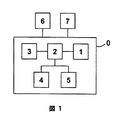
図は、車両環境監視ユニット0の、本発明によるビデオ画像表示装置1の概略的な構成またはレイアウトの一例を示す図である。このため、車両環境監視ユニット0は画像センサ3を含み、この画像センサ3を用いて環境(周囲)情報が得られる。検出された環境情報は、コンピュータ(プロセッサユニット)2を介して画像情報へと処理され、ビデオ画像表示装置1上に表示される。その上、画像情報は中間記憶装置4内に格納される。最後に記録された画像は、画像処理アルゴリズム5を使用して中間記憶装置4内に格納された画像情報と比較される。比較の枠組みにおいては、補足的な車両運転パラメータ6が考慮に入れられる。本明細書においては、格納されている画像情報と最後に記録された画像とで許容できない偏差があった場合には、表示のビデオ画像が修正される。その上、車両運転者には、この種の許容できない偏差があった場合には、車両環境監視ユニット0と接続されている警告手段7によって警告される。
FIG. 1 is a diagram showing an example of a schematic configuration or layout of a video
0 車両環境監視ユニット
1 ビデオ画像表示装置
2 コンピュータ
3 画像センサ
4 中間記憶装置
5 画像処理アルゴリズム
6 運転パラメータ
7 警告手段
DESCRIPTION OF SYMBOLS 0 Vehicle
Claims (13)
環境情報が、少なくとも1台の画像センサ(3)を使用して取得され、
取得された前記環境情報が、コンピュータ(2)を使用して画像情報へと処理され、ビデオ画像表示装置(1)上に表示され、
前記画像情報が、中間記憶装置(4)にさらに記録され、
最後に記録された画像が、画像処理アルゴリズム(5)に基づいて、前記中間記憶装置内に格納された画像情報と比較され、前記最後に記録された画像と格納された前記画像情報との間に許容できない偏差があった場合には、前記表示されたビデオ画像が修正され、
前記最後に記録された画像と格納された前記画像情報との間の比較の枠組みにおいて、車両運転パラメータ(6)が追加的に考慮に入れられることを特徴とする、ビデオ画像表示装置(1)。 A video image display device (1) for a vehicle environment monitoring unit (0), comprising:
Environmental information is acquired using at least one image sensor (3);
The acquired environment information is processed into image information using the computer (2) and displayed on the video image display device (1).
The image information is further recorded in the intermediate storage device (4),
The last recorded image is compared with the image information stored in the intermediate storage device based on the image processing algorithm (5), and between the last recorded image and the stored image information. If there is an unacceptable deviation, the displayed video image is corrected,
Video image display device (1), characterized in that vehicle operating parameters (6) are additionally taken into account in the framework of comparison between the last recorded image and the stored image information .
Applications Claiming Priority (1)
| Application Number | Priority Date | Filing Date | Title |
|---|---|---|---|
| DE10313002A DE10313002B4 (en) | 2003-03-24 | 2003-03-24 | Vehicle environment detection unit |
Publications (1)
| Publication Number | Publication Date |
|---|---|
| JP2005294878A true JP2005294878A (en) | 2005-10-20 |
Family
ID=32798063
Family Applications (1)
| Application Number | Title | Priority Date | Filing Date |
|---|---|---|---|
| JP2004085973A Pending JP2005294878A (en) | 2003-03-24 | 2004-03-24 | Video display device for vehicle environment monitoring unit |
Country Status (4)
| Country | Link |
|---|---|
| US (1) | US20040189448A1 (en) |
| EP (1) | EP1462820B1 (en) |
| JP (1) | JP2005294878A (en) |
| DE (1) | DE10313002B4 (en) |
Cited By (1)
| Publication number | Priority date | Publication date | Assignee | Title |
|---|---|---|---|---|
| US20160134841A1 (en) * | 2014-11-10 | 2016-05-12 | David Christopher Round | Verifying information on an electronic display with an incorporated monitoring device |
Families Citing this family (15)
| Publication number | Priority date | Publication date | Assignee | Title |
|---|---|---|---|---|
| DE102005055350A1 (en) * | 2005-11-21 | 2007-05-24 | Robert Bosch Gmbh | Method for controlling the visual field size of a video system and video system for a motor vehicle |
| JP2009060404A (en) * | 2007-08-31 | 2009-03-19 | Denso Corp | Video processing device |
| DE102009028760A1 (en) * | 2009-08-20 | 2011-02-24 | Robert Bosch Gmbh | Method for testing the environment of a motor vehicle |
| DE102013206707A1 (en) * | 2013-04-15 | 2014-10-16 | Robert Bosch Gmbh | Method for checking an environment detection system of a vehicle |
| CN103448615B (en) * | 2013-08-15 | 2016-04-20 | 余姚市江腾塑业有限公司 | Vehicle-mounted pick-up control system |
| EP2865575B1 (en) * | 2013-10-22 | 2022-08-24 | Honda Research Institute Europe GmbH | Confidence estimation for predictive driver assistance systems based on plausibility rules |
| EP3094075B1 (en) * | 2014-01-10 | 2022-05-11 | Hitachi Astemo, Ltd. | In-vehicle-camera image processing device |
| DE102014207897A1 (en) * | 2014-04-28 | 2015-10-29 | Robert Bosch Gmbh | Method for generating a display image |
| CN105946714A (en) * | 2016-05-16 | 2016-09-21 | 乐视控股(北京)有限公司 | Automotive panoramic observation system and panoramic all-around observation automobile |
| CN105922936A (en) * | 2016-05-16 | 2016-09-07 | 乐视控股(北京)有限公司 | Vehicle-mounted image shooting device and vehicle |
| CN105922937A (en) * | 2016-05-16 | 2016-09-07 | 乐视控股(北京)有限公司 | Vehicle-mounted image shooting device and vehicle |
| US11104273B2 (en) | 2016-12-08 | 2021-08-31 | Robert Bosch Gmbh | Arrangement to prevent erroneous image orientation for rear view camera |
| EP3533667B1 (en) * | 2018-03-01 | 2020-09-16 | KNORR-BREMSE Systeme für Nutzfahrzeuge GmbH | Apparatus and method for monitoring a vehicle camera system |
| DE102018127059B4 (en) | 2018-10-30 | 2024-10-10 | Mercedes-Benz Group AG | Method for checking at least one environment detection sensor of a vehicle |
| DE102019002487A1 (en) | 2019-04-04 | 2020-10-08 | Daimler Ag | Method for checking a surroundings detection sensor of a vehicle and method for operating a vehicle |
Citations (5)
| Publication number | Priority date | Publication date | Assignee | Title |
|---|---|---|---|---|
| JPH08240833A (en) * | 1995-03-02 | 1996-09-17 | Mitsubishi Electric Corp | Exposure control device for vehicle camera |
| JPH09113221A (en) * | 1995-10-17 | 1997-05-02 | Mitsubishi Electric Corp | Vehicle-mounted image processing apparatus and image processing method thereof |
| JP2000134608A (en) * | 1998-10-22 | 2000-05-12 | Fujitsu Ten Ltd | Rear monitoring device for vehicle |
| JP2002077708A (en) * | 2000-09-01 | 2002-03-15 | Hitachi Ltd | Image processing system and electronic news coverage system |
| JP2002154393A (en) * | 2000-11-22 | 2002-05-28 | Mazda Motor Corp | Vehicle failure display device |
Family Cites Families (23)
| Publication number | Priority date | Publication date | Assignee | Title |
|---|---|---|---|---|
| US6324453B1 (en) * | 1998-12-31 | 2001-11-27 | Automotive Technologies International, Inc. | Methods for determining the identification and position of and monitoring objects in a vehicle |
| US4931930A (en) * | 1988-04-19 | 1990-06-05 | Industrial Technology Research Institute | Automatic parking device for automobile |
| FR2679357B1 (en) * | 1991-07-19 | 1997-01-31 | Matra Sep Imagerie Inf | ON-BOARD DEVICE AND METHOD FOR TRACKING AND MONITORING THE POSITION OF A VEHICLE ON THE ROAD AND DRIVING AID DEVICE INCLUDING APPLICATION. |
| DE4332612C2 (en) * | 1992-09-25 | 1996-02-22 | Yazaki Corp | Exterior view monitoring method for motor vehicles |
| JP2983407B2 (en) * | 1993-03-31 | 1999-11-29 | 三菱電機株式会社 | Image tracking device |
| US7049945B2 (en) * | 2000-05-08 | 2006-05-23 | Automotive Technologies International, Inc. | Vehicular blind spot identification and monitoring system |
| DE69518128T2 (en) * | 1994-09-21 | 2001-03-29 | Kabushiki Kaisha Toshiba, Kawasaki | Image data processing device with image data dividing function and method for processing image data |
| JPH08263784A (en) * | 1995-03-23 | 1996-10-11 | Honda Motor Co Ltd | Road condition recognition device |
| US5574426A (en) * | 1995-06-30 | 1996-11-12 | Insys, Ltd. | Obstacle detection system for vehicles moving in reverse |
| US6130707A (en) * | 1997-04-14 | 2000-10-10 | Philips Electronics N.A. Corp. | Video motion detector with global insensitivity |
| DE19806373A1 (en) * | 1998-02-17 | 1999-08-26 | Mannesmann Vdo Ag | Method and device for checking the functioning of a distance control device of a motor vehicle |
| DE19813300C2 (en) * | 1998-03-26 | 2003-12-11 | Bosch Gmbh Robert | display device |
| US6268803B1 (en) * | 1998-08-06 | 2001-07-31 | Altra Technologies Incorporated | System and method of avoiding collisions |
| DE60009000T2 (en) * | 1999-10-21 | 2005-03-10 | Matsushita Electric Industrial Co., Ltd., Kadoma | Parking assistance system |
| US6411867B1 (en) * | 1999-10-27 | 2002-06-25 | Fujitsu Ten Limited | Vehicle driving support system, and steering angle detection device |
| JP2001211466A (en) * | 2000-01-27 | 2001-08-03 | Toshiba Corp | Image processing system with self-diagnosis function |
| WO2001085496A1 (en) * | 2000-05-12 | 2001-11-15 | Kabushiki Kaisha Toyota Jidoshokki | Vehicle backing support apparatus |
| JP4953498B2 (en) * | 2000-07-12 | 2012-06-13 | 富士重工業株式会社 | Outside vehicle monitoring device with fail-safe function |
| JP2002325250A (en) * | 2001-02-16 | 2002-11-08 | Ki Sun Kim | Video and audio recording device for vehicles |
| JP2002319091A (en) * | 2001-04-20 | 2002-10-31 | Fuji Heavy Ind Ltd | Following vehicle recognition device |
| JP4425495B2 (en) * | 2001-06-08 | 2010-03-03 | 富士重工業株式会社 | Outside monitoring device |
| US7123168B2 (en) * | 2002-04-25 | 2006-10-17 | Donnelly Corporation | Driving separation distance indicator |
| US7266220B2 (en) * | 2002-05-09 | 2007-09-04 | Matsushita Electric Industrial Co., Ltd. | Monitoring device, monitoring method and program for monitoring |
-
2003
- 2003-03-24 DE DE10313002A patent/DE10313002B4/en not_active Expired - Fee Related
-
2004
- 2004-03-02 EP EP04004796A patent/EP1462820B1/en not_active Expired - Lifetime
- 2004-03-24 JP JP2004085973A patent/JP2005294878A/en active Pending
- 2004-03-24 US US10/807,720 patent/US20040189448A1/en not_active Abandoned
Patent Citations (5)
| Publication number | Priority date | Publication date | Assignee | Title |
|---|---|---|---|---|
| JPH08240833A (en) * | 1995-03-02 | 1996-09-17 | Mitsubishi Electric Corp | Exposure control device for vehicle camera |
| JPH09113221A (en) * | 1995-10-17 | 1997-05-02 | Mitsubishi Electric Corp | Vehicle-mounted image processing apparatus and image processing method thereof |
| JP2000134608A (en) * | 1998-10-22 | 2000-05-12 | Fujitsu Ten Ltd | Rear monitoring device for vehicle |
| JP2002077708A (en) * | 2000-09-01 | 2002-03-15 | Hitachi Ltd | Image processing system and electronic news coverage system |
| JP2002154393A (en) * | 2000-11-22 | 2002-05-28 | Mazda Motor Corp | Vehicle failure display device |
Cited By (1)
| Publication number | Priority date | Publication date | Assignee | Title |
|---|---|---|---|---|
| US20160134841A1 (en) * | 2014-11-10 | 2016-05-12 | David Christopher Round | Verifying information on an electronic display with an incorporated monitoring device |
Also Published As
| Publication number | Publication date |
|---|---|
| EP1462820A1 (en) | 2004-09-29 |
| DE10313002B4 (en) | 2006-03-23 |
| EP1462820B1 (en) | 2012-02-29 |
| US20040189448A1 (en) | 2004-09-30 |
| DE10313002A1 (en) | 2004-10-21 |
Similar Documents
| Publication | Publication Date | Title |
|---|---|---|
| JP2005294878A (en) | Video display device for vehicle environment monitoring unit | |
| US7693662B2 (en) | Drive recorder for vehicle | |
| US11050929B2 (en) | Driver recorder, display control method and program | |
| JP2008283431A (en) | Image processing device | |
| US10991086B2 (en) | Adhered substance detection apparatus | |
| US20210084227A1 (en) | Method and apparatus for the spatially resolved detection of an object outside a transportation vehicle with the aid of a sensor installed in a transportation vehicle | |
| JPWO2018042976A1 (en) | IMAGE GENERATION DEVICE, IMAGE GENERATION METHOD, RECORDING MEDIUM, AND IMAGE DISPLAY SYSTEM | |
| US11279371B2 (en) | Method, system and vehicle for use of an object displaying device in a vehicle | |
| JP7057074B2 (en) | On-board unit and driving support device | |
| JP6552285B2 (en) | In-vehicle display device and vehicle rear image display method | |
| JP3659110B2 (en) | In-vehicle image processing device | |
| KR102497614B1 (en) | Adaptive univeral monitoring system and driving method threrof | |
| JP5513190B2 (en) | Vehicle rear monitoring device and vehicle rear monitoring method | |
| JP4561627B2 (en) | Vehicle periphery monitoring device | |
| CN118082692A (en) | Holographic image starting method, device, vehicle and storage medium | |
| JP2020092365A (en) | In-vehicle camera device and in-vehicle camera dirt detection method | |
| US11097661B1 (en) | Method for operating a display arrangement of a motor vehicle, and motor vehicle | |
| KR100833704B1 (en) | Peripheral sensing method for cars | |
| KR101728670B1 (en) | AVM system having a function of identifying foreign material on camera and method thereof | |
| EP4279316A1 (en) | Apparatus and method for message notification | |
| JP2006044295A (en) | Alarming device for vehicle | |
| KR20200082463A (en) | Video recording apparatus and operating method for the same | |
| KR20100054295A (en) | System for preventing clash accident of cars using photographing image of blind spot | |
| JP2022099139A (en) | Monitor system, monitor method, and program | |
| CN120056864A (en) | Device, method and vehicle for detecting the unadiation of a warning light |
Legal Events
| Date | Code | Title | Description |
|---|---|---|---|
| A621 | Written request for application examination |
Free format text: JAPANESE INTERMEDIATE CODE: A621 Effective date: 20070123 |
|
| RD02 | Notification of acceptance of power of attorney |
Free format text: JAPANESE INTERMEDIATE CODE: A7422 Effective date: 20070710 |
|
| RD04 | Notification of resignation of power of attorney |
Free format text: JAPANESE INTERMEDIATE CODE: A7424 Effective date: 20070720 |
|
| A977 | Report on retrieval |
Free format text: JAPANESE INTERMEDIATE CODE: A971007 Effective date: 20090619 |
|
| A131 | Notification of reasons for refusal |
Free format text: JAPANESE INTERMEDIATE CODE: A131 Effective date: 20090624 |
|
| A02 | Decision of refusal |
Free format text: JAPANESE INTERMEDIATE CODE: A02 Effective date: 20091119 |