JP2005294832A - Method for forming an electrode structure useful in an energy storage device - Google Patents
Method for forming an electrode structure useful in an energy storage device Download PDFInfo
- Publication number
- JP2005294832A JP2005294832A JP2005097102A JP2005097102A JP2005294832A JP 2005294832 A JP2005294832 A JP 2005294832A JP 2005097102 A JP2005097102 A JP 2005097102A JP 2005097102 A JP2005097102 A JP 2005097102A JP 2005294832 A JP2005294832 A JP 2005294832A
- Authority
- JP
- Japan
- Prior art keywords
- binder
- current collector
- carbon
- energy storage
- electrode structure
- Prior art date
- Legal status (The legal status is an assumption and is not a legal conclusion. Google has not performed a legal analysis and makes no representation as to the accuracy of the status listed.)
- Pending
Links
Classifications
-
- H—ELECTRICITY
- H01—ELECTRIC ELEMENTS
- H01G—CAPACITORS; CAPACITORS, RECTIFIERS, DETECTORS, SWITCHING DEVICES, LIGHT-SENSITIVE OR TEMPERATURE-SENSITIVE DEVICES OF THE ELECTROLYTIC TYPE
- H01G11/00—Hybrid capacitors, i.e. capacitors having different positive and negative electrodes; Electric double-layer [EDL] capacitors; Processes for the manufacture thereof or of parts thereof
- H01G11/84—Processes for the manufacture of hybrid or EDL capacitors, or components thereof
- H01G11/86—Processes for the manufacture of hybrid or EDL capacitors, or components thereof specially adapted for electrodes
-
- H—ELECTRICITY
- H01—ELECTRIC ELEMENTS
- H01G—CAPACITORS; CAPACITORS, RECTIFIERS, DETECTORS, SWITCHING DEVICES, LIGHT-SENSITIVE OR TEMPERATURE-SENSITIVE DEVICES OF THE ELECTROLYTIC TYPE
- H01G11/00—Hybrid capacitors, i.e. capacitors having different positive and negative electrodes; Electric double-layer [EDL] capacitors; Processes for the manufacture thereof or of parts thereof
- H01G11/22—Electrodes
- H01G11/26—Electrodes characterised by their structure, e.g. multi-layered, porosity or surface features
- H01G11/28—Electrodes characterised by their structure, e.g. multi-layered, porosity or surface features arranged or disposed on a current collector; Layers or phases between electrodes and current collectors, e.g. adhesives
-
- H—ELECTRICITY
- H01—ELECTRIC ELEMENTS
- H01G—CAPACITORS; CAPACITORS, RECTIFIERS, DETECTORS, SWITCHING DEVICES, LIGHT-SENSITIVE OR TEMPERATURE-SENSITIVE DEVICES OF THE ELECTROLYTIC TYPE
- H01G11/00—Hybrid capacitors, i.e. capacitors having different positive and negative electrodes; Electric double-layer [EDL] capacitors; Processes for the manufacture thereof or of parts thereof
- H01G11/22—Electrodes
- H01G11/30—Electrodes characterised by their material
- H01G11/32—Carbon-based
-
- H—ELECTRICITY
- H01—ELECTRIC ELEMENTS
- H01M—PROCESSES OR MEANS, e.g. BATTERIES, FOR THE DIRECT CONVERSION OF CHEMICAL ENERGY INTO ELECTRICAL ENERGY
- H01M4/00—Electrodes
- H01M4/02—Electrodes composed of, or comprising, active material
- H01M4/04—Processes of manufacture in general
-
- H—ELECTRICITY
- H01—ELECTRIC ELEMENTS
- H01M—PROCESSES OR MEANS, e.g. BATTERIES, FOR THE DIRECT CONVERSION OF CHEMICAL ENERGY INTO ELECTRICAL ENERGY
- H01M4/00—Electrodes
- H01M4/02—Electrodes composed of, or comprising, active material
- H01M4/04—Processes of manufacture in general
- H01M4/0402—Methods of deposition of the material
- H01M4/0419—Methods of deposition of the material involving spraying
-
- H—ELECTRICITY
- H01—ELECTRIC ELEMENTS
- H01M—PROCESSES OR MEANS, e.g. BATTERIES, FOR THE DIRECT CONVERSION OF CHEMICAL ENERGY INTO ELECTRICAL ENERGY
- H01M4/00—Electrodes
- H01M4/02—Electrodes composed of, or comprising, active material
- H01M4/04—Processes of manufacture in general
- H01M4/043—Processes of manufacture in general involving compressing or compaction
- H01M4/0435—Rolling or calendering
-
- H—ELECTRICITY
- H01—ELECTRIC ELEMENTS
- H01M—PROCESSES OR MEANS, e.g. BATTERIES, FOR THE DIRECT CONVERSION OF CHEMICAL ENERGY INTO ELECTRICAL ENERGY
- H01M4/00—Electrodes
- H01M4/02—Electrodes composed of, or comprising, active material
- H01M4/04—Processes of manufacture in general
- H01M4/0471—Processes of manufacture in general involving thermal treatment, e.g. firing, sintering, backing particulate active material, thermal decomposition, pyrolysis
-
- H—ELECTRICITY
- H01—ELECTRIC ELEMENTS
- H01M—PROCESSES OR MEANS, e.g. BATTERIES, FOR THE DIRECT CONVERSION OF CHEMICAL ENERGY INTO ELECTRICAL ENERGY
- H01M4/00—Electrodes
- H01M4/02—Electrodes composed of, or comprising, active material
- H01M4/13—Electrodes for accumulators with non-aqueous electrolyte, e.g. for lithium-accumulators; Processes of manufacture thereof
- H01M4/139—Processes of manufacture
- H01M4/1393—Processes of manufacture of electrodes based on carbonaceous material, e.g. graphite-intercalation compounds or CFx
-
- H—ELECTRICITY
- H01—ELECTRIC ELEMENTS
- H01M—PROCESSES OR MEANS, e.g. BATTERIES, FOR THE DIRECT CONVERSION OF CHEMICAL ENERGY INTO ELECTRICAL ENERGY
- H01M4/00—Electrodes
- H01M4/02—Electrodes composed of, or comprising, active material
- H01M4/36—Selection of substances as active materials, active masses, active liquids
- H01M4/58—Selection of substances as active materials, active masses, active liquids of inorganic compounds other than oxides or hydroxides, e.g. sulfides, selenides, tellurides, halogenides or LiCoFy; of polyanionic structures, e.g. phosphates, silicates or borates
- H01M4/583—Carbonaceous material, e.g. graphite-intercalation compounds or CFx
-
- H—ELECTRICITY
- H01—ELECTRIC ELEMENTS
- H01M—PROCESSES OR MEANS, e.g. BATTERIES, FOR THE DIRECT CONVERSION OF CHEMICAL ENERGY INTO ELECTRICAL ENERGY
- H01M4/00—Electrodes
- H01M4/02—Electrodes composed of, or comprising, active material
- H01M4/62—Selection of inactive substances as ingredients for active masses, e.g. binders, fillers
- H01M4/621—Binders
- H01M4/622—Binders being polymers
-
- H—ELECTRICITY
- H01—ELECTRIC ELEMENTS
- H01M—PROCESSES OR MEANS, e.g. BATTERIES, FOR THE DIRECT CONVERSION OF CHEMICAL ENERGY INTO ELECTRICAL ENERGY
- H01M4/00—Electrodes
- H01M4/86—Inert electrodes with catalytic activity, e.g. for fuel cells
- H01M4/88—Processes of manufacture
- H01M4/8825—Methods for deposition of the catalytic active composition
- H01M4/886—Powder spraying, e.g. wet or dry powder spraying, plasma spraying
-
- H—ELECTRICITY
- H01—ELECTRIC ELEMENTS
- H01M—PROCESSES OR MEANS, e.g. BATTERIES, FOR THE DIRECT CONVERSION OF CHEMICAL ENERGY INTO ELECTRICAL ENERGY
- H01M4/00—Electrodes
- H01M4/86—Inert electrodes with catalytic activity, e.g. for fuel cells
- H01M4/88—Processes of manufacture
- H01M4/8878—Treatment steps after deposition of the catalytic active composition or after shaping of the electrode being free-standing body
- H01M4/8882—Heat treatment, e.g. drying, baking
-
- H—ELECTRICITY
- H01—ELECTRIC ELEMENTS
- H01M—PROCESSES OR MEANS, e.g. BATTERIES, FOR THE DIRECT CONVERSION OF CHEMICAL ENERGY INTO ELECTRICAL ENERGY
- H01M4/00—Electrodes
- H01M4/86—Inert electrodes with catalytic activity, e.g. for fuel cells
- H01M4/88—Processes of manufacture
- H01M4/8878—Treatment steps after deposition of the catalytic active composition or after shaping of the electrode being free-standing body
- H01M4/8896—Pressing, rolling, calendering
-
- H—ELECTRICITY
- H01—ELECTRIC ELEMENTS
- H01M—PROCESSES OR MEANS, e.g. BATTERIES, FOR THE DIRECT CONVERSION OF CHEMICAL ENERGY INTO ELECTRICAL ENERGY
- H01M4/00—Electrodes
- H01M4/86—Inert electrodes with catalytic activity, e.g. for fuel cells
- H01M4/96—Carbon-based electrodes
-
- H—ELECTRICITY
- H01—ELECTRIC ELEMENTS
- H01M—PROCESSES OR MEANS, e.g. BATTERIES, FOR THE DIRECT CONVERSION OF CHEMICAL ENERGY INTO ELECTRICAL ENERGY
- H01M4/00—Electrodes
- H01M4/02—Electrodes composed of, or comprising, active material
- H01M4/62—Selection of inactive substances as ingredients for active masses, e.g. binders, fillers
- H01M4/624—Electric conductive fillers
-
- H—ELECTRICITY
- H01—ELECTRIC ELEMENTS
- H01M—PROCESSES OR MEANS, e.g. BATTERIES, FOR THE DIRECT CONVERSION OF CHEMICAL ENERGY INTO ELECTRICAL ENERGY
- H01M4/00—Electrodes
- H01M4/02—Electrodes composed of, or comprising, active material
- H01M4/64—Carriers or collectors
- H01M4/66—Selection of materials
- H01M4/661—Metal or alloys, e.g. alloy coatings
-
- Y—GENERAL TAGGING OF NEW TECHNOLOGICAL DEVELOPMENTS; GENERAL TAGGING OF CROSS-SECTIONAL TECHNOLOGIES SPANNING OVER SEVERAL SECTIONS OF THE IPC; TECHNICAL SUBJECTS COVERED BY FORMER USPC CROSS-REFERENCE ART COLLECTIONS [XRACs] AND DIGESTS
- Y02—TECHNOLOGIES OR APPLICATIONS FOR MITIGATION OR ADAPTATION AGAINST CLIMATE CHANGE
- Y02E—REDUCTION OF GREENHOUSE GAS [GHG] EMISSIONS, RELATED TO ENERGY GENERATION, TRANSMISSION OR DISTRIBUTION
- Y02E60/00—Enabling technologies; Technologies with a potential or indirect contribution to GHG emissions mitigation
- Y02E60/10—Energy storage using batteries
-
- Y—GENERAL TAGGING OF NEW TECHNOLOGICAL DEVELOPMENTS; GENERAL TAGGING OF CROSS-SECTIONAL TECHNOLOGIES SPANNING OVER SEVERAL SECTIONS OF THE IPC; TECHNICAL SUBJECTS COVERED BY FORMER USPC CROSS-REFERENCE ART COLLECTIONS [XRACs] AND DIGESTS
- Y02—TECHNOLOGIES OR APPLICATIONS FOR MITIGATION OR ADAPTATION AGAINST CLIMATE CHANGE
- Y02E—REDUCTION OF GREENHOUSE GAS [GHG] EMISSIONS, RELATED TO ENERGY GENERATION, TRANSMISSION OR DISTRIBUTION
- Y02E60/00—Enabling technologies; Technologies with a potential or indirect contribution to GHG emissions mitigation
- Y02E60/13—Energy storage using capacitors
-
- Y—GENERAL TAGGING OF NEW TECHNOLOGICAL DEVELOPMENTS; GENERAL TAGGING OF CROSS-SECTIONAL TECHNOLOGIES SPANNING OVER SEVERAL SECTIONS OF THE IPC; TECHNICAL SUBJECTS COVERED BY FORMER USPC CROSS-REFERENCE ART COLLECTIONS [XRACs] AND DIGESTS
- Y02—TECHNOLOGIES OR APPLICATIONS FOR MITIGATION OR ADAPTATION AGAINST CLIMATE CHANGE
- Y02E—REDUCTION OF GREENHOUSE GAS [GHG] EMISSIONS, RELATED TO ENERGY GENERATION, TRANSMISSION OR DISTRIBUTION
- Y02E60/00—Enabling technologies; Technologies with a potential or indirect contribution to GHG emissions mitigation
- Y02E60/30—Hydrogen technology
- Y02E60/50—Fuel cells
Landscapes
- Chemical & Material Sciences (AREA)
- Engineering & Computer Science (AREA)
- Chemical Kinetics & Catalysis (AREA)
- General Chemical & Material Sciences (AREA)
- Electrochemistry (AREA)
- Manufacturing & Machinery (AREA)
- Power Engineering (AREA)
- Materials Engineering (AREA)
- Microelectronics & Electronic Packaging (AREA)
- Physics & Mathematics (AREA)
- Thermal Sciences (AREA)
- Inorganic Chemistry (AREA)
- Electric Double-Layer Capacitors Or The Like (AREA)
- Battery Electrode And Active Subsutance (AREA)
Abstract
Description
本発明は、電極構造を形成する方法に関する。より詳細には、本発明は、エネルギー貯蔵装置(energy storage device)において使用する電極構造を形成する方法に関する。 The present invention relates to a method of forming an electrode structure. More particularly, the present invention relates to a method of forming an electrode structure for use in an energy storage device.
エネルギー貯蔵装置のための電極構造は、従来的には粉末形態の炭素質物質、バインダーおよび溶媒を含有するスラリーから調製される。このスラリーを、典型的にナイフブレーディング(knife blading)法を使用して金属箔集電装置上にコーティングして、集電装置(current collector)上にスラリーの薄い、平坦なコーティングを提供する。コーティングされた集電装置を次いでオーブン中で乾燥して、溶媒を除去し、バインダーを硬化させる。電極構造を次いで任意に圧延して、電気化学的活性物質の容積または充填画分を減少させ、電極構造の全多孔度を減少させることにより、集電装置上にコーティングされた電気化学的活性物質の密度を高くすることができる。 Electrode structures for energy storage devices are conventionally prepared from a slurry containing a carbonaceous material in powder form, a binder and a solvent. This slurry is coated onto a metal foil current collector, typically using a knife blade method, to provide a thin, flat coating of the slurry on the current collector. The coated current collector is then dried in an oven to remove the solvent and cure the binder. The electrode structure is then optionally rolled to reduce the volume or filling fraction of the electrochemically active material, thereby reducing the total porosity of the electrode structure, thereby coating the electrochemically active material on the current collector The density of can be increased.
この方法中の溶媒の使用に関して、電極アセンブリーを形成する、かかる従来方法に関連する多様な不利益が存在する。たとえば、これらの従来方法における溶媒の使用は、揮発性有機化合物(VOC)の環境中への放出に関係する環境問題;かかる溶媒の使用と結び付いた追加のコスト、たとえば電極構造からの溶媒の十分な除去を確実にするために必要とされる増加したオーブン乾燥時間から生じる追加のエネルギーコスト、を生じさせる場合がある。 There are various disadvantages associated with such conventional methods of forming electrode assemblies for the use of solvents in this method. For example, the use of solvents in these conventional methods is an environmental issue associated with the release of volatile organic compounds (VOCs) into the environment; additional costs associated with the use of such solvents, such as sufficient solvent from the electrode structure May result in additional energy costs resulting from the increased oven drying time required to ensure proper removal.
従来の電極アセンブリー法と関連した不利益を克服する一つの試みが、Firsichの米国特許第5,993,996号に開示されている。Firsichは、とりわけ、除去可能なバッキング材上に炭化可能バインダーおよび炭化可能ポリマー前駆体をスプレーコーティングすることによる炭素電極モノリスの形成を開示している。スプレーコートされた材料は、炭化の前または後にバッキング材から除去することができる。炭化された物質は、引き続きの酸処理によって活性化および官能化することができる。しかしながら、活性化された炭素物質を直接集電装置上に堆積するための方法であって、Firsichにより開示された引き続きの炭化を必要とせず、かつ溶媒の必要性を最小化し、または削除する方法を提供することが望まれている。 One attempt to overcome the disadvantages associated with conventional electrode assembly methods is disclosed in Firsch US Pat. No. 5,993,996. Firsch discloses, among other things, the formation of a carbon electrode monolith by spray coating a carbonizable binder and a carbonizable polymer precursor onto a removable backing material. The spray coated material can be removed from the backing material before or after carbonization. The carbonized material can be activated and functionalized by subsequent acid treatment. However, a method for depositing activated carbon material directly on a current collector that does not require the subsequent carbonization disclosed by Firsch and minimizes or eliminates the need for solvents It is desired to provide.
本発明の一態様において、(a)(i)炭素;(ii)バインダー;および任意に、(iii)導電性添加剤、を含有する混合物を集電装置上にスプレーすることにより集電装置上に多孔性電極を堆積させ;(b)(a)の生成物を加熱しバインダーを硬化させ;および任意に、(c)(b)の生成物を圧延することを含む、電極構造を形成する方法が提供される。 In one embodiment of the invention, on the current collector by spraying a mixture containing (a) (i) carbon; (ii) a binder; and optionally (iii) a conductive additive onto the current collector. Depositing a porous electrode; (b) heating the product of (a) to cure the binder; and optionally (c) rolling the product of (b) to form an electrode structure A method is provided.
本発明の他の態様において、(a)(i)炭素;(ii)バインダー;および任意に、(iii)導電性添加剤を含有する混合物、を集電装置上に静電スプレー堆積することにより集電装置上に多孔性電極を堆積させ;(b)(a)の生成物を加熱しバインダーを硬化させ;および任意に、(c)(b)の生成物を圧延することを含む、電極構造を形成する方法が提供される。 In another aspect of the invention, by electrostatic spray depositing (a) (i) carbon; (ii) a binder; and optionally (iii) a mixture containing a conductive additive on a current collector. Depositing a porous electrode on the current collector; (b) heating the product of (a) to cure the binder; and optionally (c) rolling the product of (b) A method of forming a structure is provided.
本発明の他の態様において、(a)集電装置を前処理して、その表面エネルギーを変更し、(b)(i)炭素;(ii)バインダー;および任意に、(iii)導電性添加剤、を含有する混合物を集電装置上にスプレーすることにより改質された集電装置上に多孔性電極を堆積させ;(b)(a)の生成物を加熱しバインダーを硬化させ;および任意に、(c)(b)の生成物を圧延することを含む、電極構造を形成する方法が提供される。 In another embodiment of the invention, (a) pretreating the current collector to change its surface energy; (b) (i) carbon; (ii) a binder; and optionally (iii) a conductive addition Depositing a porous electrode on the modified current collector by spraying a mixture containing an agent on the current collector; (b) heating the product of (a) to cure the binder; and Optionally, a method of forming an electrode structure is provided that includes rolling the product of (c) (b).
本発明の他の態様において、(a)本発明の方法により調製された少なくとも二つの電極構造;(b)少なくとも二つの電極構造の間に挟まれた少なくとも一つの多孔性セパレーター;および(c)少なくとも二つの電極構造および少なくとも一つの多孔性セパレーターと接触する電解液を含む、長期使用可能な2層キャパシタが提供される。 In another embodiment of the present invention, (a) at least two electrode structures prepared by the method of the present invention; (b) at least one porous separator sandwiched between at least two electrode structures; and (c) A two-layer capacitor is provided that can be used for a long period of time, comprising an electrolyte in contact with at least two electrode structures and at least one porous separator.
本発明の他の態様において、本発明の方法により調製された電極構造を含有するエネルギー貯蔵装置が提供される。 In another aspect of the present invention, an energy storage device is provided containing an electrode structure prepared by the method of the present invention.
本発明の他の態様において、自動車、パワークオリティシステム、エンジン始動システム、光電池のためのエネルギー貯蔵システム、風車のためのエネルギー貯蔵システム、医療システム、移動推進力システム、軍事エレクトロニクスシステム、輸送システム、商業用エレクトロニクスシステム、消費エレクトロニクスシステム、携帯エレクトロニクスシステム、オーディオシステムおよび消費機器を含む多様なシステムにおける本発明のエネルギー貯蔵装置の用途が提供される。 In other aspects of the invention, automobiles, power quality systems, engine starting systems, energy storage systems for photovoltaic cells, energy storage systems for windmills, medical systems, mobile propulsion systems, military electronics systems, transportation systems, commercial Applications of the energy storage device of the present invention are provided in various systems including consumer electronics systems, consumer electronics systems, portable electronics systems, audio systems and consumer devices.
本発明の堆積方法の使用は、使用者および環境の双方に優しい物質を使用する。従来の液体コーティング適用方法に利用される、有害で不安定な有機溶媒キャリヤーの必要性は、実質的に取り除かれる。従って、本発明の堆積方法は、揮発性物質の環境への放出が、たとえあったとしても、わずかであり;それにより、かかる揮発性物質と関連した空気汚染および健康問題の双方を緩和することになる。さらに、本発明の方法は、過剰にスプレーされた物質の容易な再使用可能性に少なくとも部分的に基づいた、非常に高いコーティング効率を発揮する。たとえば、本発明の一態様においては、スプレーされた粉末の少なくとも75重量%;あるいはスプレーされた粉末の少なくとも85重量%は、集電装置に移動し、そこに定着する。残存する粉末を、容易に回収し、90重量%以上の率で再使用することができる。 The use of the deposition method of the present invention uses materials that are both user and environmentally friendly. The need for harmful and unstable organic solvent carriers utilized in conventional liquid coating application methods is substantially eliminated. Thus, the deposition method of the present invention has little, if any, release of volatile materials to the environment; thereby mitigating both air pollution and health problems associated with such volatile materials. become. Moreover, the method of the present invention provides very high coating efficiency based at least in part on the easy reusability of oversprayed material. For example, in one aspect of the invention, at least 75% by weight of the sprayed powder; or at least 85% by weight of the sprayed powder moves to the current collector and settles there. The remaining powder can be easily recovered and reused at a rate of 90% by weight or more.
本発明での使用に好適な堆積技術としては、たとえば、粉末式フレーム溶射、フレーム溶射熱分解、燃焼化学蒸着、高速酸素燃料溶射(high velocity oxy−fuel spraying)、大気プラズマ溶射、静電スプレー、アーク溶射、および流動浸漬が挙げられる。本発明の一態様において、静電スプレー堆積技術が使用される。本発明の一態様において、微粉砕炭素およびバインダーの混合物は、静電荷が付与され、集電装置に推進される。本発明の他の態様において、標準陰性コロナ静電スプレーガンを、アース接地された集電装置上に炭素およびバインダーの混合物を堆積させるのに使用することができる。かかるスプレーガンの例としては、米国、オハイオ州、アムハーストのNordson Corporationから商業的に入手可能なVersaSprayIIがある。 Suitable deposition techniques for use in the present invention include, for example, powder flame spraying, flame spray pyrolysis, combustion chemical vapor deposition, high velocity oxy-fuel spraying, atmospheric plasma spraying, electrostatic spraying, Examples include arc spraying and fluidized immersion. In one aspect of the invention, electrostatic spray deposition techniques are used. In one aspect of the invention, the mixture of finely divided carbon and binder is imparted with an electrostatic charge and propelled to a current collector. In another embodiment of the invention, a standard negative corona electrostatic spray gun can be used to deposit a mixture of carbon and binder on a grounded current collector. An example of such a spray gun is VersaSpray II, commercially available from Nordson Corporation, Amherst, Ohio, USA.
炭素、バインダーおよび任意に導電性添加剤の、スプレーされる混合物は、たとえば、伝導性、対流性、放射性、誘導的熱エネルギー、電磁放射エネルギーまたはそれらの組合わせにより硬化される。一態様において、炭素、バインダーおよび任意に、導電性添加剤の、スプレーされる混合物は、バインダーのガラス転移温度より上であるが、バインダーの分解温度より下の温度まで、2〜120分間;あるいは2〜60分間;あるいは2〜30分間、加熱される。 The sprayed mixture of carbon, binder and optionally conductive additive is cured, for example, by conductivity, convection, radiation, inductive thermal energy, electromagnetic radiation energy, or combinations thereof. In one embodiment, the sprayed mixture of carbon, binder and optionally conductive additive is above the glass transition temperature of the binder but below the decomposition temperature of the binder for 2 to 120 minutes; or Heat for 2 to 60 minutes; alternatively 2 to 30 minutes.
本発明の方法は、任意に集電装置の前処理操作を含むことができる。たとえば、集電装置を表面処理に付して、その表面エネルギーを変更し、そのぬれ性および/またはその付着特性を促進することができる。 The method of the present invention can optionally include a pre-processing operation of the current collector. For example, the current collector can be subjected to a surface treatment to change its surface energy and promote its wettability and / or its adhesion characteristics.
本発明の使用に好適な集電装置の表面前処理操作としては、たとえば、コロナエッチング、メカニカルアブレーション、化学エッチング、熱処理および化学処理が挙げられる。 Examples of current collector surface pretreatment operations suitable for use in the present invention include corona etching, mechanical ablation, chemical etching, heat treatment and chemical treatment.
一態様において、本発明の方法により堆積される多孔性電極は、25〜500μm;あるいは50〜250μm;あるいは50〜150μmの平均硬化厚を示す。 In one embodiment, the porous electrode deposited by the method of the present invention exhibits an average cured thickness of 25-500 μm; alternatively 50-250 μm; alternatively 50-150 μm.
一態様において、本発明の方法により形成される多孔性電極は、10%未満;あるいは5%未満;あるいは2%未満;あるいは1%未満まで変動する均一な厚さを示す。 In one embodiment, the porous electrode formed by the method of the present invention exhibits a uniform thickness that varies to less than 10%; alternatively less than 5%; alternatively less than 2%; alternatively less than 1%.
本発明の電極構造に使用する好適な集電装置を、実質的に任意の導電体から製造することができる。当業者は、所定の用途の集電装置のための構築に適した材料を選択することを認知している。たとえば、当業者は、二層ウルトラキャパシタに組み入れられる電極構造についての集電装置は、デバイスに使用される電解物質に対し電気化学的および化学的防食性を発揮する導電性物質から製造されるべきであることを認識している。一態様において、集電装置を、アルミニウム、ステンレス鋼、亜鉛、チタン、タンタル、銅、金、ニッケルまたはこれらの組合わせから選択される材料;あるいは銅およびアルミニウムから選択される材料;あるいはアルミニウムから製造することができる。 A suitable current collector for use in the electrode structure of the present invention can be manufactured from virtually any conductor. Those skilled in the art are aware of selecting materials suitable for construction for current collectors for a given application. For example, those skilled in the art will recognize that current collectors for electrode structures incorporated in double-layer ultracapacitors should be manufactured from conductive materials that exhibit electrochemical and chemical protection against electrolytes used in devices. I recognize that. In one embodiment, the current collector is made of aluminum, stainless steel, zinc, titanium, tantalum, copper, gold, nickel or a combination thereof; or a material selected from copper and aluminum; or manufactured from aluminum can do.
一態様において、集電装置は、たとえば、箔、三次元構造の発泡金属、エキスパンデッドメタル、網、メッシュ、ウールまたはこれらの組合わせを含む形態となり得る。この態様の一側面においては、集電装置はアルミニウム箔から製造することができる。 In one embodiment, the current collector can be in a form that includes, for example, foil, three-dimensional foam metal, expanded metal, mesh, mesh, wool, or combinations thereof. In one aspect of this embodiment, the current collector can be manufactured from aluminum foil.
一態様において、本発明の集電装置は、5〜500μm;あるいは5〜100μm;あるいは5〜50μmの平均厚を示す。 In one embodiment, the current collector of the present invention exhibits an average thickness of 5 to 500 μm; alternatively 5 to 100 μm; alternatively 5 to 50 μm.
本発明の一態様において、炭素、バインダーおよび任意に導電性添加剤、の混合物は、50〜98重量%の炭素;あるいは50〜95重量%の炭素;あるいは50〜90重量%の炭素、あるいは50〜85重量%の炭素、あるいは50〜80重量%の炭素を含むことができる。 In one embodiment of the invention, the mixture of carbon, binder and optionally conductive additive is 50-98 wt% carbon; alternatively 50-95 wt% carbon; alternatively 50-90 wt% carbon, alternatively 50 It can contain ˜85 wt% carbon, alternatively 50-80 wt% carbon.
本発明の一態様において、炭素、バインダーおよび任意に導電性添加剤、の混合物は、50重量%を超えないバインダー;あるいは0.5〜50重量%のバインダー;あるいは2〜50重量%のバインダー、あるいは15重量%未満のバインダー、あるいは0.5〜10重量%のバインダー、あるいは5重量%未満のバインダーを含むことができる。 In one embodiment of the present invention, the mixture of carbon, binder and optionally conductive additive comprises no more than 50 wt% binder; alternatively 0.5-50 wt% binder; alternatively 2-50 wt% binder, Alternatively, it may comprise less than 15 wt% binder, alternatively 0.5-10 wt% binder, alternatively less than 5 wt% binder.
本発明の一態様において、炭素、バインダーおよび任意に導電性添加剤、の混合物は、10重量%以下の導電性添加剤;あるいは5重量%未満の導電性添加剤;あるいは2重量%未満の導電性添加剤を含むことができる。 In one embodiment of the invention, the mixture of carbon, binder and optionally conductive additive is 10 wt% or less conductive additive; alternatively less than 5 wt% conductive additive; alternatively less than 2 wt% conductive. Sex additives may be included.
本発明の使用に好適な炭素としては、たとえば、活性炭、マクロレティキュラー炭素、カーボンナノチューブおよびフラーレンが挙げられる。 Suitable carbons for use in the present invention include, for example, activated carbon, macroreticular carbon, carbon nanotubes and fullerenes.
一態様において、炭素は、10F/gをこえる静電容量を発揮する活性炭である。 In one embodiment, the carbon is activated carbon that exhibits a capacitance greater than 10 F / g.
他の態様において、炭素は、Brunauer、Emmett、Teller(BET)分析法を使用して決定される表面積が少なくとも50m2/g、あるいは50〜3,000m2/g、あるいは少なくとも500m2/g、あるいは500〜2,500m2/g、あるいは800〜2,500m2/g、あるいは1,000〜2,500m2/g、あるいは1,300〜2,500m2/g、あるいは1,500〜2,500m2/gを示す活性炭である。 In another embodiment, the carbon, Brunauer, Emmett, Teller (BET ) analysis of at least 50 m 2 / g surface area that is determined using, or 50~3,000m 2 / g, or at least 500 meters 2 / g, Alternatively 500~2,500m 2 / g, or 800~2,500m 2 / g, or 1,000~2,500m 2 / g or 1,300~2,500m 2 / g, or 1,500~2, , 500 m 2 / g.
他の態様において、炭素は、窒素吸着技術により0.1cm3/gより大きい細孔容積を示す活性炭である。 In other embodiments, the carbon is activated carbon that exhibits a pore volume greater than 0.1 cm 3 / g by the nitrogen adsorption technique.
他の態様において、炭素は、Horvath−Kawazoe(H−K)法により0.1と5.0nmの間に少なくとも一つのピークを有する細孔サイズ分布を示す活性炭である。 In another embodiment, the carbon is activated carbon that exhibits a pore size distribution with at least one peak between 0.1 and 5.0 nm by the Horvath-Kawazoe (HK) method.
他の態様において、炭素は、Barrett−Joyner−Halenda(BJH)法により2.0と50.0nmの間に少なくとも一つのピークを有する細孔サイズ分布を示す。 In another embodiment, the carbon exhibits a pore size distribution with at least one peak between 2.0 and 50.0 nm by the Barrett-Joyner-Halenda (BJH) method.
他の態様において、炭素は、H−K dv/dlog(W)細孔サイズ分布を使用して測定した場合に2nm以下の細孔サイズにおいて少なくとも一つの第一の明確なピークを有し、およびBJH dv/dlog(D)細孔サイズ分布を使用して測定した場合に2nmより大きい、あるいは3nmより大きい、あるいは5nmより大きい、あるいは10nmより大きい、あるいは12.5nmより大きい細孔サイズにおいて少なくとも一つの第二の明確なピークを有する細孔サイズ分布を示す。 In other embodiments, the carbon has at least one first distinct peak at a pore size of 2 nm or less as measured using H-K dv / dlog (W) pore size distribution, and At least one at a pore size greater than 2 nm, alternatively greater than 3 nm, alternatively greater than 5 nm, alternatively greater than 10 nm, or greater than 12.5 nm as measured using the BJH dv / dlog (D) pore size distribution. 2 shows a pore size distribution with two second distinct peaks.
他の態様において、炭素は、50μm未満の容積平均粒径を示す活性炭である。 In other embodiments, the carbon is activated carbon that exhibits a volume average particle size of less than 50 μm.
他の態様において、炭素は、ミクロポア、メソポアおよびマクロポアの分布、ならびに少なくとも500m2/gのBET表面積を示し、そのBET表面積の10〜80%が1.7〜10,000nmの直径を有する細孔に寄与している活性炭である。 In other embodiments, the carbon exhibits a micropore, mesopore and macropore distribution, and a pore having a BET surface area of at least 500 m 2 / g, wherein 10-80% of the BET surface area has a diameter of 1.7-10,000 nm. Activated carbon that contributes to
他の態様において、炭素は、10F/gより大きい静電容量;50m2/gより大きい、あるいは50〜3,000m2/g、あるいは少なくとも500m2/g、あるいは500〜2,500m2/g、あるいは800〜2,500m2/g、あるいは1,000〜2,500m2/g、あるいは1,300〜2,500m2/g、あるいは1,500〜2,500m2/gのBET表面積;0.1cm3/gより大きい細孔容積;0.1と50nmの間に少なくとも一つのピークを有する細孔サイズ分布および50μm未満の容積平均粒径を示す活性炭である。この態様の一側面においては、炭素はマクロレティキュラー炭素質物質である。この態様の他の側面において、炭素は粉末である。 In another embodiment, the carbon, 10F / g greater than the capacitance; greater than 50 m 2 / g, or 50~3,000m 2 / g, or at least 500 meters 2 / g or 500~2,500m 2 / g, or 800~2,500m 2 / g or 1,000~2,500m 2 / g or 1,300~2,500m 2 / g or a BET surface area of 1,500~2,500m 2 / g,,,; Pore volume greater than 0.1 cm 3 / g; activated carbon exhibiting a pore size distribution with at least one peak between 0.1 and 50 nm and a volume average particle size of less than 50 μm. In one aspect of this embodiment, the carbon is a macroreticular carbonaceous material. In another aspect of this embodiment, the carbon is a powder.
本発明についての使用に好適な活性炭は、たとえば、フェノール−ホルムアルデヒドポリマー、メラミン−ホルムアルデヒドポリマー、レゾルシノール−ホルムアルデヒドポリマー、ポリアニリン、ポリアクリロニトリル、キネル(kynel)、レーヨン、ココナツ殻、炭水化物(たとえばスクロース)、ピッチ、木材およびこれらの混合物を含む多様な出発物質から製造することができる。 Activated carbons suitable for use with the present invention include, for example, phenol-formaldehyde polymers, melamine-formaldehyde polymers, resorcinol-formaldehyde polymers, polyaniline, polyacrylonitrile, quinel, rayon, coconut shells, carbohydrates (eg sucrose), pitch. Can be made from a variety of starting materials, including wood and mixtures thereof.
本発明の使用に好適なバインダーとしては、たとえば、ポリアミド、ポリエステル、セルロースエステル、メチルセルロース、(メタ)アクリレート、ポリ(メタ)アクリレート、ポリエチレン、ポリプロピレン、ポリ塩化ビニル(PVC)、ポリフッ化ビニリデン(PVDF)、ポリフェニルスルホン、ポリビニルピロリドン、ポリテトラフルオロエチレン(PTFE)、発泡ポリテトラフルオロエチレン(ePTFE)、エチレンプロピレンジエンモノマー(EPDM)、高分子量ポリエチレン(UHMWPE)、スチレン類およびこれらの組み合わせが挙げられる。本発明の使用に好適な商業的に入手可能なバインダーは、米国、ペンシルバニア州、フィラデルフィアのAtofina Chemicalsから入手可能なKynar(登録商標)761およびKynar(登録商標)2801が含まれる。当業者は、本発明の電極構造を含む与えられた装置における使用に好適なバインダー物質を選択することを認知している。たとえば、二層ウルトラキャパシタにおいて使用される電極構造については、当業者は、デバイスに使用される電極と両立し得るバインダー材料を選択することを認知している。 Suitable binders for use in the present invention include, for example, polyamide, polyester, cellulose ester, methylcellulose, (meth) acrylate, poly (meth) acrylate, polyethylene, polypropylene, polyvinyl chloride (PVC), and polyvinylidene fluoride (PVDF). , Polyphenylsulfone, polyvinylpyrrolidone, polytetrafluoroethylene (PTFE), expanded polytetrafluoroethylene (ePTFE), ethylene propylene diene monomer (EPDM), high molecular weight polyethylene (UHMWPE), styrenes, and combinations thereof. Commercially available binders suitable for use in the present invention include Kynar® 761 and Kynar® 2801 available from Atofina Chemicals, Philadelphia, Pennsylvania, USA. Those skilled in the art are aware of selecting a binder material suitable for use in a given device containing the electrode structure of the present invention. For example, for electrode structures used in double-layer ultracapacitors, those skilled in the art recognize that they select a binder material that is compatible with the electrodes used in the device.
一態様において、バインダーは、5μm以下の容積平均粒径を示す。他の態様において、バインダーは、炭素によって示された容積平均粒径の50%を超えない容積平均粒径を示す。 In one embodiment, the binder exhibits a volume average particle size of 5 μm or less. In other embodiments, the binder exhibits a volume average particle size not exceeding 50% of the volume average particle size exhibited by carbon.
本発明の使用に好適な導電性添加剤としては、たとえば、カーボンブラック、グラファイト、酸化チタン、酸化ルテニウムおよびこれらの混合物が挙げられる。一態様において、導電性添加剤は、伝導性炭素を含有する。この態様の一側面において、伝導性炭素は、カーボンブラック、グラファイトおよびこれらの混合物である。本発明の使用に好適な商業的に入手可能なカーボンブラックとしては、たとえば、Akzo NobelおよびCarbot Corporationからそれぞれ入手可能なketjen blackおよびアセチレンブラックが含まれる。他の態様において、導電性添加剤は、50μm以下の容積平均粒径を示す。 Suitable conductive additives for use in the present invention include, for example, carbon black, graphite, titanium oxide, ruthenium oxide, and mixtures thereof. In one embodiment, the conductive additive contains conductive carbon. In one aspect of this embodiment, the conductive carbon is carbon black, graphite, and mixtures thereof. Commercially available carbon blacks suitable for use in the present invention include, for example, ketjen black and acetylene black available from Akzo Nobel and Carbot Corporation, respectively. In other embodiments, the conductive additive exhibits a volume average particle size of 50 μm or less.
本発明の電極構造は、たとえば、電気二層キャパシタ(また、ウルトラキャパシタとしても知られる)、バッテリー、燃料電池、動力安定装置および電子容量型脱イオン化装置を含む多様なエネルギー貯蔵装置に使用することができる。本発明の電極構造を含むエネルギー貯蔵装置は、たとえば、自動車システム、エンジン始動システム、光電池のためのエネルギー貯蔵システム、風車のためのエネルギー貯蔵システム、医療システム、移動推進力システム、軍事エレクトロニクスシステム、輸送システム、商業用エレクトロニクスシステム、消費者用エレクトロニクスシステム、携帯エレクトロニクスシステム、オーディオシステムおよび消費者用機器を含む多様なシステムにおいて使用することができる。 The electrode structure of the present invention is used in a variety of energy storage devices including, for example, electric double layer capacitors (also known as ultracapacitors), batteries, fuel cells, power stabilizers and electronic capacitive deionization devices. Can do. The energy storage device including the electrode structure of the present invention includes, for example, an automobile system, an engine start system, an energy storage system for a photovoltaic cell, an energy storage system for a windmill, a medical system, a mobile propulsion system, a military electronics system, transportation It can be used in a variety of systems including systems, commercial electronics systems, consumer electronics systems, portable electronics systems, audio systems and consumer equipment.
一態様において、本発明の電極構造は、キャパシタにおいて使用することができる。この態様の一側面は、キャパシタは本発明の方法により調製された少なくとも二つの電極構造、少なくとも二つの電極構造の間に挟まれた少なくとも一つの多孔性セパレーター、並びにその少なくとも二つの電極構造および少なくとも一つの多孔性セパレーターと接触している電解液を含有する二層キャパシタである。 In one aspect, the electrode structure of the present invention can be used in a capacitor. In one aspect of this embodiment, the capacitor comprises at least two electrode structures prepared by the method of the present invention, at least one porous separator sandwiched between at least two electrode structures, and at least two electrode structures and at least A two-layer capacitor containing an electrolyte in contact with one porous separator.
本発明の使用に好適な電解液としては、たとえば、有機電解液および電解水溶液が挙げられる。一態様において、電解液は、有機電解液である。この態様の一側面において、有機電解液は、電解質を有機溶媒または有機溶媒の混合物中に溶解させることにより得ることができる。 Suitable electrolytes for use in the present invention include, for example, organic electrolytes and aqueous electrolyte solutions. In one embodiment, the electrolytic solution is an organic electrolytic solution. In one aspect of this embodiment, the organic electrolyte can be obtained by dissolving the electrolyte in an organic solvent or a mixture of organic solvents.
本発明の電解液においての使用に好適な有機溶媒としては、たとえば、電気化学的に安定なエチレンカーボネート;プロピレンカーボネート;ブチレンカーボネート;γ−ブチロラクトン;スルホラン;スルホラン誘導体;3−メチルスルホラン;1,2−ジメトキシエタン;アセトニトリル;グルタロニトリル;バレロニトリル;ジメチルホルムアミド;ジメチルスルホキシド;テトラヒドロフラン;ジメトキシエタン;メチルホルメート;ジメチルカーボネート;ジエチルカーボネート;エチルメチルカーボネートおよびこれらの混合物が挙げられる。 Suitable organic solvents for use in the electrolyte of the present invention include, for example, electrochemically stable ethylene carbonate; propylene carbonate; butylene carbonate; γ-butyrolactone; sulfolane; sulfolane derivatives; 3-methylsulfolane; -Dimethoxyethane; acetonitrile; glutaronitrile; valeronitrile; dimethylformamide; dimethyl sulfoxide; tetrahydrofuran; dimethoxyethane; methyl formate; dimethyl carbonate; diethyl carbonate: ethyl methyl carbonate and mixtures thereof.
有機溶媒との使用について好適な電解質としては、たとえば、R1R2R3R4N+またはR1R2R3R4P+で表される第4級オニウムカチオンを有する塩が挙げられる。ここで、R1、R2、R3およびR4はそれぞれ独立してC1〜6アルキル基および、たとえば、BF4 −、PF6 −、ClO4 −、CF3SO3 −および(SO2R5)(SO2R6)N−から選択されるアニオンであり、ここで、R5およびR6はそれぞれ独立してC1〜4アルキル基、アルキレン基および組合された環構造である。一態様において、電解質は(C2H5)4NBF4、(C2H5)3(CH3)NBF4、(C2H5)4PBF4および(C2H5)3(CH3)PBF4を含む群から選択される。一態様において、記載された塩の一つを、0.1〜2.5モル/L、あるいは0.5〜2モル/Lの濃度において有機溶液に溶解することができる。 Suitable electrolytes for use with organic solvents include, for example, salts having a quaternary onium cation represented by R 1 R 2 R 3 R 4 N + or R 1 R 2 R 3 R 4 P +. . Here, R 1 , R 2 , R 3 and R 4 are each independently a C 1-6 alkyl group and, for example, BF 4 − , PF 6 − , ClO 4 − , CF 3 SO 3 — and (SO 2 R 5) (SO 2 R 6 ) N - is an anion selected from, wherein, R 5 and R 6 are each independently C 1 to 4 alkyl group, an alkylene group and combined ring structure. In one aspect, the electrolyte comprises (C 2 H 5 ) 4 NBF 4 , (C 2 H 5 ) 3 (CH 3 ) NBF 4 , (C 2 H 5 ) 4 PBF 4 and (C 2 H 5 ) 3 (CH 3 ) Selected from the group comprising PBF 4 ; In one embodiment, one of the described salts can be dissolved in an organic solution at a concentration of 0.1 to 2.5 mol / L, alternatively 0.5 to 2 mol / L.
本発明での使用に好適なセパレーターは、たとえば、ポリプロピレン繊維の不織布、グラスファイバーの不織布、合成セルロース、天然セルロースまたはこれらの組合わせから製造することができる。 Suitable separators for use in the present invention can be produced, for example, from polypropylene fiber nonwovens, glass fiber nonwovens, synthetic cellulose, natural cellulose, or combinations thereof.
本発明のいくつかの態様は、下記の実施例にここで詳細に記載される。実施例において下記に示される全ての画分およびパーセンテージは、断りのない限り重量による。 Some aspects of the invention are now described in detail in the Examples below. All fractions and percentages indicated below in the examples are by weight unless otherwise indicated.
実施例1
電極構造の調製
三つの異なる活性炭を、実施例1〜36において使用した。
Example 1
Preparation of Electrode Structure Three different activated carbons were used in Examples 1-36.
「BP−15」として表Iに示された炭素は、日本のクラレケミカルからBP−15として商業的に入手可能である。 The carbon shown in Table I as “BP-15” is commercially available as BP-15 from Kuraray Chemical, Japan.
「EGL−572」として表Iに示された炭素は、米国、ペンシルバニア州、フィラデルフィアのローム・アンド・ハースカンパニーから商業的に入手可能な製品Ambersorb(商標)572を30ミクロン未満の粒径まで粉砕することにより調製した。 The carbons shown in Table I as “EGL-572” were produced from the Ambersorb ™ 572, commercially available from Rohm and Haas Company, Philadelphia, Pennsylvania, USA, to particle sizes below 30 microns. Prepared by grinding.
「EGL−923」として表Iに示された炭素は、米国、ペンシルバニア州、フィラデルフィアのローム・アンド・ハースカンパニーから商業的に入手可能な製品Amberlite(商標)XAD−761を1,000℃において炭化し、次に二酸化炭素のもとで活性化することにより調製した。これらの条件下で製造されたマクロレティキュラー炭素を、次いで、30ミクロン未満の粒径まで粉砕した。 The carbon shown in Table I as “EGL-923” is a product of Amberlite ™ XAD-761, commercially available from Rohm and Haas Company, Philadelphia, Pennsylvania, USA at 1,000 ° C. Prepared by carbonization and then activation under carbon dioxide. The macroreticular carbon produced under these conditions was then ground to a particle size of less than 30 microns.
六つの異なるバインダーを、実施例1〜36において使用した。 Six different binders were used in Examples 1-36.
「PVDF」として表Iに示されたバインダーは、米国、ペンシルバニア州、フィラデルフィアのAtofina ChemicalsからKynar(登録商標)711として商業的に入手可能である。 The binder shown in Table I as “PVDF” is commercially available as Kynar® 711 from Atofina Chemicals, Philadelphia, Pennsylvania, USA.
「PTFE」として表Iに示されたバインダーは、米国、ニュージャーシー州、デイトンのShamrock Technologies,Inc.からFluoro(商標)C−369として商業的に入手可能である。 Binders shown in Table I as “PTFE” are available from Shamrock Technologies, Inc. of Dayton, NJ, USA. Commercially available as Fluoro ™ C-369.
「AP」として表Iに示されたバインダーは、実施例2に記載されたエマルションポリマーを乾燥して粉末形態にすることにより調製された、12重量%ポリ(ブチルアクリレート)/88重量%ポリ(メチルメタクリレート)エマルションポリマーのアクリル粉末である。 The binders shown in Table I as “AP” were prepared by drying the emulsion polymer described in Example 2 to powder form, 12 wt% poly (butyl acrylate) / 88 wt% poly ( Methyl methacrylate) emulsion polymer acrylic powder.
「AE」として表Iに示されたバインダーは、実施例2に記載された手順を使用して調製された、水性、12重量%ポリ(ブチルアクリレート)/88重量%ポリ(メチルメタクリレート)エマルションポリマーのアクリルエマルションである。 The binders shown in Table I as “AE” are aqueous, 12 wt% poly (butyl acrylate) / 88 wt% poly (methyl methacrylate) emulsion polymer prepared using the procedure described in Example 2. Acrylic emulsion.
「Epoxy」として表Iに示されたバインダーは、米国、ニューヨーク州、タリータウンのチバスペシャリティーケミカルズからAraldite(登録商標)GT7013として商業的に入手可能である。 The binder shown in Table I as “Epoxy” is commercially available as Araldite® GT7013 from Ciba Specialty Chemicals, Tarrytown, NY, USA.
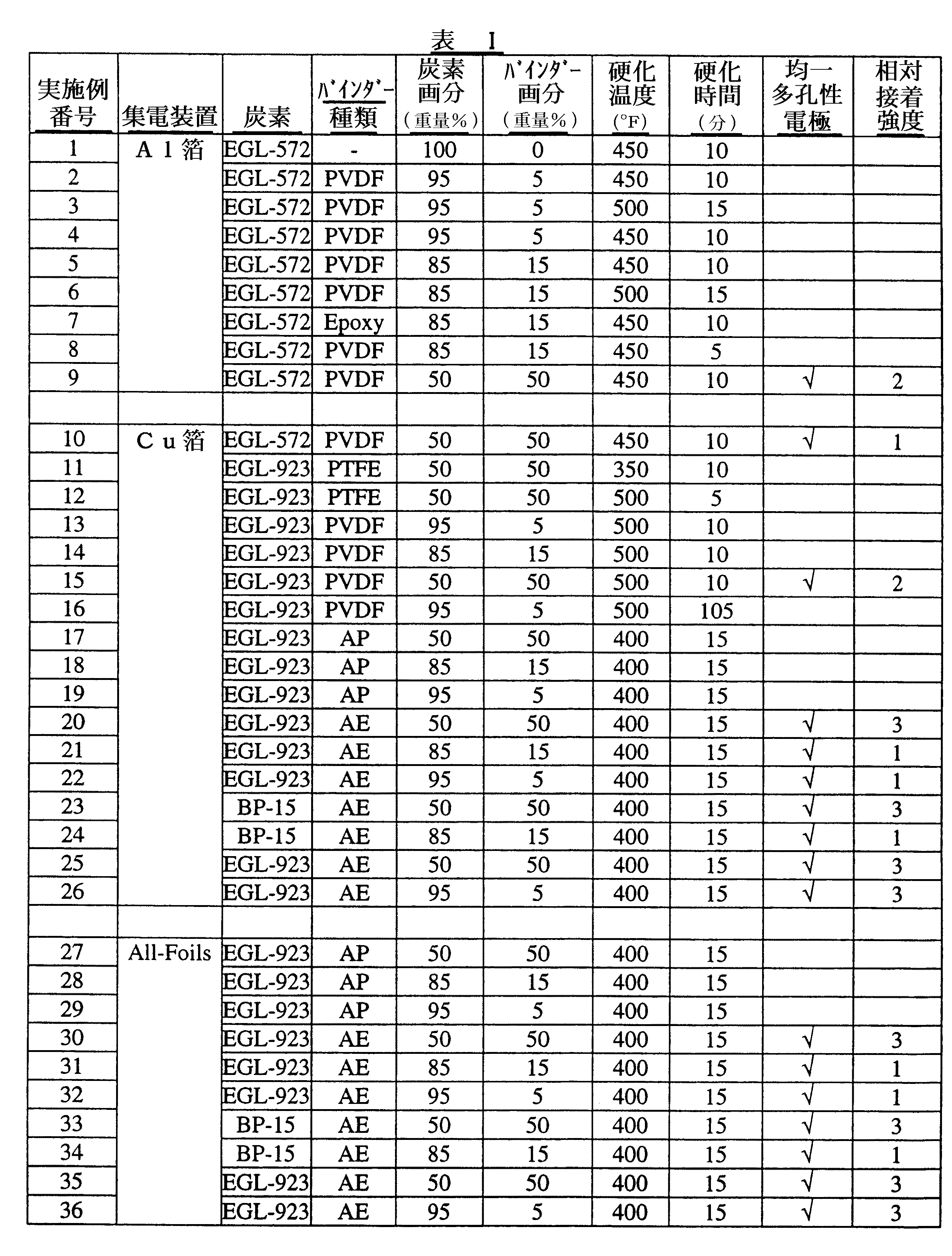
実施例2〜19および27〜29のそれぞれにおいて、乾燥粉末化活性炭を、表Iに記載の画分においてAPと混合した。 In each of Examples 2-19 and 27-29, dry powdered activated carbon was mixed with AP in the fractions listed in Table I.
実施例20〜26および30〜36のそれぞれにおいて、乾燥粉末化活性炭を、表Iに記載の画分においてAEと混合し、次いで真空下で60℃において24時間乾燥した。 In each of Examples 20-26 and 30-36, dry powdered activated carbon was mixed with AE in the fractions listed in Table I and then dried under vacuum at 60 ° C. for 24 hours.
実施例2〜36のそれぞれにおいて、活性炭およびバインダーの混合物を、30秒〜5分、IKA(登録商標)A11ベーシックミキサーを使用して機械的に混合した。 In each of Examples 2-36, the activated carbon and binder mixture was mechanically mixed using an IKA® A11 basic mixer for 30 seconds to 5 minutes.
三つの異なる金属を、実施例1〜36において集電装置として使用した。「Al箔」として表Iに示された集電装置材は、米国、バージニア州、リッチモンドのAlco Inc.の一部門、Reynolds Consumer Productsからダイアモンドアルミニウムフォイルとして商業的に入手可能である。「Cu箔」として表Iに示された集電装置材は、米国、ニューヨーク州、フーシックフォールのOak Mitsui Companyから商業的に入手可能である。「All−Foils」として表Iに示された集電装置材は、米国、オハイオ州、クリーブランドのAll−Foilsから商業的に入手可能なアルミニウム箔である。 Three different metals were used as current collectors in Examples 1-36. Current collector materials shown in Table I as “Al foil” are available from Alco Inc. of Richmond, Virginia, USA. It is commercially available as a diamond aluminum foil from a division, Reynolds Consumer Products. The current collector materials shown in Table I as “Cu foil” are commercially available from Oak Mitsui Company, Hoosick Fall, NY, USA. The current collector material shown in Table I as “All-Foils” is an aluminum foil that is commercially available from All-Foils, Cleveland, Ohio, USA.
実施例1〜36のそれぞれにおいて、活性炭/バインダー混合物を、米国、オハイオ州、アムハーストのNordson Corporationから入手可能な標準陰性コロナ静電スプレーガンである重力送りVersaSprayIIを使用して、表Iに示された集電装置材の75mm×125mm片上に静電堆積した。静電堆積プロセスの間、集電装置材をアース接地した。静電スプレーガンの制御パラメーターは次の通りであった。すなわち、10psiのフィード空気圧、10psiのノズル空気圧および100kVの電圧であった。 In each of Examples 1-36, the activated carbon / binder mixture is shown in Table I using a gravity-feed VersaSpray II, a standard negative corona electrostatic spray gun available from Nordson Corporation, Amherst, Ohio, USA. Electrostatic deposition was performed on a 75 mm × 125 mm piece of the current collector material. The current collector material was grounded during the electrostatic deposition process. The control parameters for the electrostatic spray gun were as follows: That is, 10 psi feed air pressure, 10 psi nozzle air pressure and 100 kV voltage.
実施例1〜36において、集電装置上に堆積された炭素/バインダー混合物を有する集電装置を、米国、イリノイ州、ブルーアイランドのBlue M Electric Co.から商業的に入手可能なモデルNo.OV−580C−2対流オーブンにおいて、熱硬化した。オーブンを、各実施例のそれぞれについて表Iにおいて記載された温度に加熱した。集電装置上に堆積された炭素/バインダー混合物を有する集電装置を、次いで表Iに記載された期間、記載された温度においてオーブン温度を維持しながらオーブン中で硬化した。 In Examples 1-36, a current collector having a carbon / binder mixture deposited on a current collector was purchased from Blue M Electric Co., Blue Island, Illinois, USA. Model No. commercially available from Thermosetting was in an OV-580C-2 convection oven. The oven was heated to the temperature described in Table I for each of the examples. The current collector with the carbon / binder mixture deposited on the current collector was then cured in the oven while maintaining the oven temperature at the indicated temperature for the time period described in Table I.
実施例1〜36のそれぞれの結果は、表Iにおいて提供される。均一な多孔性電極の堆積を生じた各実施例は、表Iにおいて「均一多孔性電極」欄において、チェックマークで示される。均一な多孔性電極は、目視検査による決定をした場合に、集電装置を完全に覆い、かつそれに接着する炭素/バインダーの均一な層として定義される。表Iは、また、実施例9、10、15、20〜26および30〜36(即ち、均一な多孔性電極の堆積を生じる各実施例)において堆積された多孔性電極により発揮された相対接着強度の表示を含む。「1」は、多孔性電極が比較的貧弱な接着を発揮したことを示す。「2」は、多孔性電極が比較的良好な接着を発揮したことを示す。「3」は、多孔性電極が比較的強い接着を発揮したことを示す。多孔性電極の相対接着強度は、手動でこすることにより決定した。 The results for each of Examples 1-36 are provided in Table I. Each example that resulted in the deposition of a uniform porous electrode is indicated by a check mark in the “Uniform Porous Electrode” column in Table I A uniform porous electrode is defined as a uniform layer of carbon / binder that completely covers and adheres to the current collector as determined by visual inspection. Table I also shows the relative adhesion exerted by the porous electrodes deposited in Examples 9, 10, 15, 20-26 and 30-36 (ie, each example that results in the deposition of a uniform porous electrode). Includes intensity indication. “1” indicates that the porous electrode exhibited relatively poor adhesion. “2” indicates that the porous electrode exhibited relatively good adhesion. “3” indicates that the porous electrode exhibited relatively strong adhesion. The relative adhesion strength of the porous electrode was determined by manual rubbing.
実施例2
BA/MMAエマルションポリマーバインダーの調製
12重量%のポリ(ブチルアクリレート)と88重量%のポリ(メチルメタクリレート)のポリマー組成物を以下の手順を使用して調製した。
Example 2
Preparation of BA / MMA Emulsion Polymer Binder A polymer composition of 12 wt% poly (butyl acrylate) and 88 wt% poly (methyl methacrylate) was prepared using the following procedure.
(A)(i)1267部の脱イオン水;
(ii)0.20部の酒石酸;
(iii)0.018部の硫酸第一鉄;および
(iV)17.8部のラウリル硫酸ナトリウムの28%水溶液
を、パドル撹拌器、加熱マントルおよび温度計を装備した5リットル、四つ口丸底フラスコに添加した。
(B)次いで、丸底フラスコの内容物を窒素でスパージしながら48℃に加熱した。
(C)第一乳化モノマー混合物(EMM)は、
(i)117.4部のメチルメタクリレート;
(ii)16.0部のブチルアクリレート;
(iii)99.5部の脱イオン水;および
(iv)3.46部のラウリル硫酸ナトリウムの28%水溶液
を混合することにより調製した。
(D)次いで、(C)の生成物を高速機械ミキサーで乳化した。
(E)次いで、(D)の生成物を丸底フラスコの内容物に添加した。
(F)丸底フラスコの内容物の反応温度を45℃に調整した。
(G)0.072部のナトリウムホルムアルデヒドスルホキシレート2水和物を、3.53部の脱イオン水に溶解した。
(H)次いで、(G)の生成物を丸底フラスコの内容物に添加した。
(I)0.074部のt−ブチルヒドロペルオキシド、および追加の0.074部のt−ブチルヒドロペルオキシド(水中70%)を次いで丸底フラスコの内容物に添加した。
(J)次いで、第二のEMMを、234.8部のメチルメタクリレート、32.0部のブチルアクリレート、144.2部の脱イオン水および1.62部のラウリル硫酸ナトリウム28%水溶液を混合することにより調製した。
(K)次いで、(J)の生成物を丸底フラスコの内容物に添加した。
(L)次いで、丸底フラスコの内容物の温度を57℃に調整した。
(M)次に、0.309部のラウリル硫酸ナトリウム28%水溶液および0.314部の70%tert−ブチルヒドロペルオキシドを丸底フラスコの内容物に添加した。
(N)次いで、第三のEMMを352.2部のメチルメタクリレート、48.0部のブチルアクリレート、193.4部の脱イオン水および2.38部のラウリル硫酸ナトリウム28%水溶液を混合することにより調製した。
(O)次いで、(N)の生成物を丸底フラスコに添加した。
(P)次いで、反応温度を52℃に調整した。
(Q)0.464部のラウリル硫酸ナトリウム28%溶液(22.7部の脱イオン水に溶解)および次いで0.460部の70%t−ブチルヒドロペルオキシドを丸底フラスコの内容物に添加した。
(R)次に、第四のEMMは
(i)469.7部のメチルメタクリレート;
(ii)64.0部のブチルアクリレート;
(iii)259.5部の脱イオン水;および
(iv)3.40部のラウリル硫酸ナトリウム28%水溶液
を混合することにより調製した。
(S)次いで、(R)の生成物を丸底フラスコの内容物に添加した。
(T)次いで、反応温度を49℃に調整した。
(U)2.14部のラウリル硫酸ナトリウム(104.6部の脱イオン水に溶解)および2.14部の過硫酸カリウム(104.6部の脱イオン水に溶解)を丸底フラスコの内容物に添加した。
(V)0.213部の28%ラウリル硫酸ナトリウム(10.4部の脱イオン水に溶解)および次いで0.322部の70%t−ブチルヒドロペルオキシドを丸底フラスコの内容物に添加した。
(W)15分後、0.213部の28%ラウリル硫酸ナトリウム(10.4部の脱イオン水に溶解)および次いで0.322部の70%t−ブチルヒドロペルオキシドを丸底フラスコの内容物に添加した。および
(X)15分後、丸底フラスコの内容物を30℃に冷却してポリマー生成物を与えた。
(A) (i) 1267 parts deionized water;
(Ii) 0.20 parts tartaric acid;
(Iii) 0.018 parts ferrous sulfate; and (iv) 17.8 parts of a 28% aqueous solution of sodium lauryl sulfate in a 5 liter, four-necked round equipped with a paddle stirrer, heating mantle and thermometer. Added to the bottom flask.
(B) The contents of the round bottom flask were then heated to 48 ° C. while sparging with nitrogen.
(C) The first emulsified monomer mixture (EMM) is
(I) 117.4 parts methyl methacrylate;
(Ii) 16.0 parts butyl acrylate;
(Iii) 99.5 parts deionized water; and (iv) 3.46 parts of a 28% aqueous solution of sodium lauryl sulfate.
(D) Next, the product of (C) was emulsified with a high-speed mechanical mixer.
(E) The product of (D) was then added to the contents of the round bottom flask.
(F) The reaction temperature of the contents of the round bottom flask was adjusted to 45 ° C.
(G) 0.072 parts sodium formaldehyde sulfoxylate dihydrate was dissolved in 3.53 parts deionized water.
(H) The product of (G) was then added to the contents of the round bottom flask.
(I) 0.074 parts t-butyl hydroperoxide and an additional 0.074 parts t-butyl hydroperoxide (70% in water) were then added to the contents of the round bottom flask.
(J) The second EMM is then mixed with 234.8 parts methyl methacrylate, 32.0 parts butyl acrylate, 144.2 parts deionized water and 1.62 parts 28% aqueous sodium lauryl sulfate. It was prepared by.
(K) The product of (J) was then added to the contents of the round bottom flask.
(L) Next, the temperature of the contents of the round bottom flask was adjusted to 57 ° C.
(M) Next, 0.309 parts of a 28% aqueous sodium lauryl sulfate solution and 0.314 parts of 70% tert-butyl hydroperoxide were added to the contents of the round bottom flask.
(N) The third EMM is then mixed with 352.2 parts methyl methacrylate, 48.0 parts butyl acrylate, 193.4 parts deionized water and 2.38 parts 28% aqueous sodium lauryl sulfate. It was prepared by.
(O) The product of (N) was then added to the round bottom flask.
(P) Next, the reaction temperature was adjusted to 52 ° C.
(Q) 0.464 parts sodium lauryl sulfate 28% solution (dissolved in 22.7 parts deionized water) and then 0.460 parts 70% t-butyl hydroperoxide were added to the contents of the round bottom flask. .
(R) Next, the fourth EMM is: (i) 469.7 parts methyl methacrylate;
(Ii) 64.0 parts butyl acrylate;
(Iii) 259.5 parts deionized water; and (iv) 3.40 parts 28% aqueous sodium lauryl sulfate solution.
(S) The product of (R) was then added to the contents of the round bottom flask.
(T) Next, the reaction temperature was adjusted to 49 ° C.
(U) Contents of round bottom flask with 2.14 parts sodium lauryl sulfate (dissolved in 104.6 parts deionized water) and 2.14 parts potassium persulfate (dissolved in 104.6 parts deionized water). Added to the product.
(V) 0.213 parts 28% sodium lauryl sulfate (dissolved in 10.4 parts deionized water) and then 0.322 parts 70% t-butyl hydroperoxide were added to the contents of the round bottom flask.
(W) After 15 minutes, 0.213 parts of 28% sodium lauryl sulfate (dissolved in 10.4 parts of deionized water) and then 0.322 parts of 70% t-butyl hydroperoxide were added to the contents of the round bottom flask. Added to. And (X) After 15 minutes, the contents of the round bottom flask were cooled to 30 ° C. to give a polymer product.
Claims (10)
(ii)バインダー;および
(iii)任意に、導電性添加剤
を含有する混合物を集電装置上にスプレーすることにより集電装置上に多孔性電極を堆積させ;さらに
(b)(a)の生成物を加熱しバインダーを硬化すること
を含む、電極構造を形成する方法。 (A) (i) carbon;
(Ii) a binder; and (iii) optionally depositing a porous electrode on the current collector by spraying a mixture containing the conductive additive onto the current collector; further (b) of (a) A method of forming an electrode structure comprising heating the product and curing the binder.
をさらに含む、請求項1に記載の方法。 The method of claim 1, further comprising rolling the product of (c) (b).
Automotive, power quality, engine startup, energy storage for photovoltaics, energy storage for windmills, medical systems, mobile propulsion systems, military electronics, transportation systems, commercial electronics, consumer electronics, portable electronics, audio systems And use of the energy storage device according to claim 9 in consumer equipment.
Applications Claiming Priority (1)
| Application Number | Priority Date | Filing Date | Title |
|---|---|---|---|
| US55804904P | 2004-03-31 | 2004-03-31 |
Publications (1)
| Publication Number | Publication Date |
|---|---|
| JP2005294832A true JP2005294832A (en) | 2005-10-20 |
Family
ID=34886346
Family Applications (1)
| Application Number | Title | Priority Date | Filing Date |
|---|---|---|---|
| JP2005097102A Pending JP2005294832A (en) | 2004-03-31 | 2005-03-30 | Method for forming an electrode structure useful in an energy storage device |
Country Status (7)
| Country | Link |
|---|---|
| US (1) | US7419745B2 (en) |
| EP (1) | EP1583169B1 (en) |
| JP (1) | JP2005294832A (en) |
| KR (1) | KR100703628B1 (en) |
| CN (1) | CN1677722A (en) |
| AU (1) | AU2005201234B2 (en) |
| TW (1) | TWI264845B (en) |
Cited By (5)
| Publication number | Priority date | Publication date | Assignee | Title |
|---|---|---|---|---|
| WO2009041076A1 (en) * | 2007-09-28 | 2009-04-02 | Nippon Chemi-Con Corporation | Electrode for electric double layer capacitor and method for producing the same |
| JP2009099935A (en) * | 2007-03-30 | 2009-05-07 | Nippon Chemicon Corp | Electrode for electric double layer capacitor and method for manufacturing the same |
| KR101008400B1 (en) * | 2007-09-27 | 2011-01-14 | 한국전력공사 | Ion adsorption electrode, electrosorption purification apparatus having the same and method for manufacturing electrode for ion adsorption |
| JP2013539245A (en) * | 2010-10-04 | 2013-10-17 | コーニング インコーポレイテッド | Electrolyte system and electrolytic cell |
| JP2014529188A (en) * | 2011-08-11 | 2014-10-30 | カーディアック ペースメイカーズ, インコーポレイテッド | Sintered capacitor electrode with three-dimensional frame structure |
Families Citing this family (29)
| Publication number | Priority date | Publication date | Assignee | Title |
|---|---|---|---|---|
| US7531596B2 (en) * | 2006-11-30 | 2009-05-12 | The Goodyear Tire & Rubber Company | Rubber composition containing antidegradant and MIBK adsorbing activated carbon, and pneumatic tire with component |
| KR101009532B1 (en) * | 2007-02-26 | 2011-01-18 | 주식회사 엘지화학 | Zinc oxide multilayer thin film and method for manufacturing same |
| WO2008109164A1 (en) * | 2007-03-08 | 2008-09-12 | Nanocomp Technologies, Inc. | Supercapacitors and methods of manufacturing same |
| KR101013155B1 (en) * | 2007-08-03 | 2011-02-10 | 한국기계연구원 | Organic solar cell using conductive polymer transparent electrode and manufacturing method |
| WO2010008392A1 (en) * | 2008-07-18 | 2010-01-21 | Meadwestvaco Corporation | Enhanced negative plates for lead acid batteries |
| US8518253B2 (en) * | 2008-12-17 | 2013-08-27 | General Electric Company | Ion-exchange device and regeneration method of ion-exchange material thereof |
| US7931985B1 (en) | 2010-11-08 | 2011-04-26 | International Battery, Inc. | Water soluble polymer binder for lithium ion battery |
| US8076026B2 (en) * | 2010-02-05 | 2011-12-13 | International Battery, Inc. | Rechargeable battery using an aqueous binder |
| US8405955B2 (en) | 2010-03-16 | 2013-03-26 | Corning Incorporated | High performance electrodes for EDLCS |
| JP5500547B2 (en) * | 2010-05-28 | 2014-05-21 | 独立行政法人産業技術総合研究所 | Electric double layer capacitor |
| US20110143206A1 (en) * | 2010-07-14 | 2011-06-16 | International Battery, Inc. | Electrode for rechargeable batteries using aqueous binder solution for li-ion batteries |
| DE102010032770A1 (en) * | 2010-07-29 | 2012-02-02 | Li-Tec Battery Gmbh | Method and device for producing a multilayer electrode structure, galvanic cell |
| US8102642B2 (en) * | 2010-08-06 | 2012-01-24 | International Battery, Inc. | Large format ultracapacitors and method of assembly |
| DE102010044552B4 (en) * | 2010-09-07 | 2015-04-02 | Fraunhofer-Gesellschaft zur Förderung der angewandten Forschung e.V. | Method for producing an electrode for a storage cell for electrical energy |
| CN102386378B (en) * | 2011-09-13 | 2016-03-02 | 东莞新能源科技有限公司 | A kind of preparation method of lithium ion battery electrode sizing agent |
| JP6265580B2 (en) * | 2011-10-06 | 2018-01-24 | 株式会社村田製作所 | Battery and manufacturing method thereof |
| CN102496467A (en) * | 2011-12-05 | 2012-06-13 | 上海奥威科技开发有限公司 | Super capacitor monomer and super capacitor power system |
| DE102013221162B4 (en) * | 2013-10-18 | 2017-11-16 | Fraunhofer-Gesellschaft zur Förderung der angewandten Forschung e.V. | Method and device for producing an electrode |
| CN103794802A (en) * | 2014-01-27 | 2014-05-14 | 中原工学院 | Method for preparing lithium battery current collector by electrostatic coating polymer composite PTC powder |
| US20160307707A1 (en) * | 2015-04-17 | 2016-10-20 | YUNASKO, Ltd. | Method for manufacturing an electrode for energy storage devices and an electrode manufactured therewith |
| CN105355470A (en) * | 2015-12-15 | 2016-02-24 | 宁波南车新能源科技有限公司 | Preparation method for ultrathin lithium titanate electrode |
| CN105914057B (en) * | 2016-05-12 | 2018-07-06 | 广东风华高新科技股份有限公司 | The preparation method of electrode slice |
| WO2019055893A1 (en) * | 2017-09-18 | 2019-03-21 | Avx Corporation | Ultracapacitor with a low leakage current |
| CN108172767A (en) * | 2017-12-26 | 2018-06-15 | 北京乐华锂能科技有限公司 | A kind of lithium ion battery electrode piece and preparation method thereof |
| EP3557676B1 (en) * | 2018-04-18 | 2025-07-30 | Brno University Of Technology | Alkali and/or alkaline earth ion - monoclinic sulfur allotrope battery with self-supporting electrodes |
| KR102738609B1 (en) * | 2019-11-08 | 2024-12-04 | 한국전기연구원 | Carbon paste coating method for manufacturing high density electrode of three-dimensional foam type current collector and electrode manufactured by the coating method |
| CN111477841A (en) * | 2020-05-26 | 2020-07-31 | 苏州凌威新能源科技有限公司 | Lithium battery pole piece and preparation method thereof |
| CN111725477A (en) * | 2020-06-16 | 2020-09-29 | 深圳市信宇人科技股份有限公司 | Preparation method of dry-process electrode material of lithium ion battery |
| CN116601782A (en) * | 2020-12-08 | 2023-08-15 | 应用材料公司 | Pre-lithiated and lithium metal-free anode coatings |
Family Cites Families (25)
| Publication number | Priority date | Publication date | Assignee | Title |
|---|---|---|---|---|
| US3899354A (en) * | 1973-09-10 | 1975-08-12 | Union Carbide Corp | Gas electrodes and a process for producing them |
| US4633372A (en) * | 1985-08-26 | 1986-12-30 | The Standard Oil Company | Polyoxometalate-modified carbon electrodes and uses therefor in capacitors |
| DE69128805T2 (en) * | 1990-03-29 | 1998-05-14 | Matsushita Electric Ind Co Ltd | Electrolytic double layer capacitor and process for its manufacture |
| JP3244691B2 (en) | 1990-10-18 | 2002-01-07 | 旭硝子株式会社 | Electric double layer capacitor |
| JPH05304050A (en) | 1992-04-27 | 1993-11-16 | Isuzu Motors Ltd | Electric double layer capacitor |
| JP3470462B2 (en) | 1995-07-18 | 2003-11-25 | トヨタ自動車株式会社 | Method for manufacturing electrode for electric double layer capacitor |
| US5657522A (en) * | 1996-05-14 | 1997-08-19 | Duracell Inc. | Coiled electrode assemblies and methods of producing same |
| US5993996A (en) * | 1997-09-16 | 1999-11-30 | Inorganic Specialists, Inc. | Carbon supercapacitor electrode materials |
| JP3466082B2 (en) * | 1998-03-31 | 2003-11-10 | 松下電器産業株式会社 | Manufacturing method of fuel cell electrode |
| US6201685B1 (en) * | 1998-10-05 | 2001-03-13 | General Electric Company | Ultracapacitor current collector |
| US6072692A (en) * | 1998-10-08 | 2000-06-06 | Asahi Glass Company, Ltd. | Electric double layer capacitor having an electrode bonded to a current collector via a carbon type conductive adhesive layer |
| US6449139B1 (en) * | 1999-08-18 | 2002-09-10 | Maxwell Electronic Components Group, Inc. | Multi-electrode double layer capacitor having hermetic electrolyte seal |
| US6297293B1 (en) * | 1999-09-15 | 2001-10-02 | Tda Research, Inc. | Mesoporous carbons and polymers |
| US6328770B1 (en) * | 1999-11-23 | 2001-12-11 | Valence Technology (Nevada), Inc. | Method of making multi-layer electrochemical cell devices |
| US6426863B1 (en) * | 1999-11-25 | 2002-07-30 | Lithium Power Technologies, Inc. | Electrochemical capacitor |
| JP2001160399A (en) | 1999-12-03 | 2001-06-12 | Toshiba Corp | Electrode of polymer electrolyte fuel cell and method of manufacturing the same |
| US6316143B1 (en) * | 1999-12-22 | 2001-11-13 | The United States Of America As Represented By The Secretary Of The Army | Electrode for rechargeable lithium-ion battery and method of fabrication |
| US6627252B1 (en) * | 2000-05-12 | 2003-09-30 | Maxwell Electronic Components, Inc. | Electrochemical double layer capacitor having carbon powder electrodes |
| US6631074B2 (en) * | 2000-05-12 | 2003-10-07 | Maxwell Technologies, Inc. | Electrochemical double layer capacitor having carbon powder electrodes |
| KR100383511B1 (en) | 2001-06-19 | 2003-05-12 | 주식회사 네스캡 | Electric energy storage device with metal layer and method for manufacturing the same |
| WO2003012908A2 (en) | 2001-07-27 | 2003-02-13 | Massachusetts Institute Of Technology | Battery structures, self-organizing structures and related methods |
| TW583153B (en) * | 2001-09-25 | 2004-04-11 | Showa Denko Kk | Carbon material, production method and use thereof |
| KR100430767B1 (en) * | 2001-11-13 | 2004-05-10 | 한국과학기술연구원 | A composite electrode, fabrication method thereof and lithium batteries comprising the same |
| JP2004072016A (en) | 2002-08-09 | 2004-03-04 | Nec Tokin Corp | Electric double layer capacitor |
| AU2013280980B2 (en) | 2012-06-25 | 2017-10-19 | Thomas Jefferson University | Compositions and methods for treating cancer with aberrant lipogenic signaling |
-
2005
- 2005-02-09 US US11/053,825 patent/US7419745B2/en not_active Expired - Fee Related
- 2005-03-18 TW TW094108276A patent/TWI264845B/en not_active IP Right Cessation
- 2005-03-19 EP EP05251693.7A patent/EP1583169B1/en not_active Expired - Lifetime
- 2005-03-22 AU AU2005201234A patent/AU2005201234B2/en not_active Ceased
- 2005-03-29 CN CNA2005100625795A patent/CN1677722A/en active Pending
- 2005-03-30 JP JP2005097102A patent/JP2005294832A/en active Pending
- 2005-03-31 KR KR1020050026935A patent/KR100703628B1/en not_active Expired - Fee Related
Cited By (7)
| Publication number | Priority date | Publication date | Assignee | Title |
|---|---|---|---|---|
| JP2009099935A (en) * | 2007-03-30 | 2009-05-07 | Nippon Chemicon Corp | Electrode for electric double layer capacitor and method for manufacturing the same |
| KR101008400B1 (en) * | 2007-09-27 | 2011-01-14 | 한국전력공사 | Ion adsorption electrode, electrosorption purification apparatus having the same and method for manufacturing electrode for ion adsorption |
| WO2009041076A1 (en) * | 2007-09-28 | 2009-04-02 | Nippon Chemi-Con Corporation | Electrode for electric double layer capacitor and method for producing the same |
| US8427811B2 (en) | 2007-09-28 | 2013-04-23 | Nippon Chemi-Con Corporation | Electrode for electric double layer capacitor and method for producing the same |
| US8824120B2 (en) | 2007-09-28 | 2014-09-02 | Nippon Chemi-Con Corporation | Electrode for electric double layer capacitor and method for producing the same |
| JP2013539245A (en) * | 2010-10-04 | 2013-10-17 | コーニング インコーポレイテッド | Electrolyte system and electrolytic cell |
| JP2014529188A (en) * | 2011-08-11 | 2014-10-30 | カーディアック ペースメイカーズ, インコーポレイテッド | Sintered capacitor electrode with three-dimensional frame structure |
Also Published As
| Publication number | Publication date |
|---|---|
| EP1583169A3 (en) | 2006-05-17 |
| US20050220989A1 (en) | 2005-10-06 |
| KR100703628B1 (en) | 2007-04-06 |
| EP1583169A2 (en) | 2005-10-05 |
| EP1583169B1 (en) | 2015-10-21 |
| AU2005201234A1 (en) | 2005-10-20 |
| US7419745B2 (en) | 2008-09-02 |
| TW200537726A (en) | 2005-11-16 |
| AU2005201234B2 (en) | 2010-09-09 |
| TWI264845B (en) | 2006-10-21 |
| CN1677722A (en) | 2005-10-05 |
| KR20060045064A (en) | 2006-05-16 |
Similar Documents
| Publication | Publication Date | Title |
|---|---|---|
| US7419745B2 (en) | Method of forming an electrode structure useful in energy storage devices | |
| Niu et al. | Compact-designed supercapacitors using free-standing single-walled carbon nanotube films | |
| CN108475587B (en) | Nonaqueous lithium-type storage element | |
| KR101056734B1 (en) | Electrode of high density supercapacitor and method of manufacturing the same | |
| CN102918614B (en) | Capacitor and manufacture method thereof | |
| KR101742593B1 (en) | Manufacturing method of crumpled graphene-carbon nanotube-polymer composite, the composite manufactured thereby and supercapacitor containing the composite | |
| WO2022085694A1 (en) | Nonaqueous alkali metal power storage element and positive electrode coating liquid | |
| KR20190055019A (en) | Carbon materials, electrode sheets and capacitors for capacitors | |
| TW201405924A (en) | Collector, electrode structure, nonaqueous electrolyte battery, and electricity storage component | |
| Zhou et al. | Carbon nanosponge cathode materials and graphite-protected etched al foil anode for dual-ion hybrid supercapacitor | |
| JP2002353074A (en) | Electric double-layer capacitor, paste for electrode used for the capacitor, and elctrode | |
| KR101629835B1 (en) | Manufacturing method of three-dimensional graphene composite via multi-doping and supercapacitor using thereof | |
| JP6829573B2 (en) | Winding non-aqueous lithium storage element | |
| JP2010205870A (en) | Electrolyte additive for electric double-layer capacitor, electrolyte, and electric double-layer capacitor | |
| Bondavalli et al. | Non-faradic carbon nanotube-based supercapacitors: state of the art: Analysis of all the main scientific contributions from 1997 to our days | |
| JP5604227B2 (en) | Method for producing activated carbon for capacitor and activated carbon | |
| JP6754659B2 (en) | Non-aqueous lithium storage element | |
| JP6754260B2 (en) | Non-aqueous lithium storage element | |
| JP2019102712A (en) | Capacitor | |
| JP2018056428A (en) | Negative electrode for non-aqueous lithium storage element | |
| HK1080611A (en) | Method of forming an electrode structure useful in energy storage devices | |
| HK1076329A (en) | Method of forming an electrode structure useful in energy storage devices | |
| JP2018056416A (en) | Nonaqueous lithium power storage element | |
| KR102348929B1 (en) | Electrode mateterial, electric double layer capacitor and method of producing the same | |
| JP6815148B2 (en) | Non-aqueous lithium storage element |
Legal Events
| Date | Code | Title | Description |
|---|---|---|---|
| RD02 | Notification of acceptance of power of attorney |
Free format text: JAPANESE INTERMEDIATE CODE: A7422 Effective date: 20061016 |
|
| A977 | Report on retrieval |
Free format text: JAPANESE INTERMEDIATE CODE: A971007 Effective date: 20071128 |
|
| A131 | Notification of reasons for refusal |
Free format text: JAPANESE INTERMEDIATE CODE: A131 Effective date: 20071210 |
|
| A601 | Written request for extension of time |
Free format text: JAPANESE INTERMEDIATE CODE: A601 Effective date: 20080304 |
|
| RD02 | Notification of acceptance of power of attorney |
Free format text: JAPANESE INTERMEDIATE CODE: A7422 Effective date: 20080304 |
|
| A602 | Written permission of extension of time |
Free format text: JAPANESE INTERMEDIATE CODE: A602 Effective date: 20080318 |
|
| A02 | Decision of refusal |
Free format text: JAPANESE INTERMEDIATE CODE: A02 Effective date: 20080804 |