JP2005294769A - Heat radiator - Google Patents
Heat radiator Download PDFInfo
- Publication number
- JP2005294769A JP2005294769A JP2004111660A JP2004111660A JP2005294769A JP 2005294769 A JP2005294769 A JP 2005294769A JP 2004111660 A JP2004111660 A JP 2004111660A JP 2004111660 A JP2004111660 A JP 2004111660A JP 2005294769 A JP2005294769 A JP 2005294769A
- Authority
- JP
- Japan
- Prior art keywords
- plate
- water
- hole
- heat
- radiator
- Prior art date
- Legal status (The legal status is an assumption and is not a legal conclusion. Google has not performed a legal analysis and makes no representation as to the accuracy of the status listed.)
- Granted
Links
- XLYOFNOQVPJJNP-UHFFFAOYSA-N water Substances O XLYOFNOQVPJJNP-UHFFFAOYSA-N 0.000 claims abstract description 56
- 239000000498 cooling water Substances 0.000 claims abstract description 18
- 238000001816 cooling Methods 0.000 claims abstract description 15
- 238000010438 heat treatment Methods 0.000 claims abstract description 10
- 230000017525 heat dissipation Effects 0.000 claims description 5
- 230000005855 radiation Effects 0.000 abstract description 8
- 230000020169 heat generation Effects 0.000 description 3
- 238000010030 laminating Methods 0.000 description 3
- 239000010949 copper Substances 0.000 description 2
- 239000004065 semiconductor Substances 0.000 description 2
- RYGMFSIKBFXOCR-UHFFFAOYSA-N Copper Chemical compound [Cu] RYGMFSIKBFXOCR-UHFFFAOYSA-N 0.000 description 1
- 230000005540 biological transmission Effects 0.000 description 1
- 238000009833 condensation Methods 0.000 description 1
- 230000005494 condensation Effects 0.000 description 1
- 229910052802 copper Inorganic materials 0.000 description 1
- 230000000694 effects Effects 0.000 description 1
- 238000005530 etching Methods 0.000 description 1
- 239000007769 metal material Substances 0.000 description 1
- 238000005192 partition Methods 0.000 description 1
- 230000002787 reinforcement Effects 0.000 description 1
- 238000005476 soldering Methods 0.000 description 1
- 239000007787 solid Substances 0.000 description 1
Images

Abstract
Description
この発明は、半導体デバイスなどの発熱体の冷却に用いる水冷式の放熱器に関する。 The present invention relates to a water-cooled radiator used for cooling a heating element such as a semiconductor device.
半導体デバイス冷却用の水冷式放熱器については、例えば特許文献1や特許文献2に記載されているが、この種の放熱器の他の従来例について図7及び図8により説明する。ここで、図7は高出力のレーザーダイオード(以下、「LD」と記す。)アレイ用の放熱器を示す縦断面図、図8の(A)は図7の矢印A方向から見た上部放熱板の下面図、(B)は同じく矢印B方向から見た中間放熱板の上面図、(C)は同じく矢印C方向から見た中間放熱板の下面図、(D)は同じく矢印D方向から見た下部放熱板の上面図である。LDアレイは、発熱密度が数十〜数百W/cm2程度と大きく、その温度上昇によりレーザー出力、効率、発信波長、素子寿命等が大きな影響を受けるが、大きさが例えば長さが10mm、幅が1〜1.5mm程度で放熱器との接触面積が小さい。そのため、空冷式では温度上昇を抑えきれないため、LDアレイ放熱器は内部に水路を設けた水冷式になっている。 A water-cooled radiator for cooling a semiconductor device is described in, for example, Patent Document 1 and Patent Document 2, and another conventional example of this type of radiator will be described with reference to FIGS. Here, FIG. 7 is a longitudinal sectional view showing a radiator for a high-power laser diode (hereinafter referred to as “LD”) array, and FIG. 8A is an upper heat radiation viewed from the direction of arrow A in FIG. A bottom view of the plate, (B) is a top view of the intermediate heat dissipation plate as seen from the direction of arrow B, (C) is a bottom view of the intermediate heat dissipation plate as seen from the direction of arrow C, and (D) is also from the direction of arrow D It is the top view of the seen lower heat sink. The LD array has a large heat generation density of about several tens to several hundreds W / cm 2, and the laser output, efficiency, transmission wavelength, element lifetime, etc. are greatly affected by the temperature rise, but the size is, for example, 10 mm in length. The width is about 1 to 1.5 mm and the contact area with the radiator is small. Therefore, since the temperature rise cannot be suppressed by the air cooling method, the LD array radiator is a water cooling method in which a water channel is provided inside.
図7及び図8において、放熱器1は一端(図の左端)をそれぞれ受熱端部とする上部放熱板2、中間放熱板3及び下部放熱板4が上下3層に積層されて構成されている。放熱器1の左右幅は例えば11mm、前後長さは例えば20mm程度である。下部放熱板2には他端(図の右端)に排水孔5が設けられ、かつこの排水孔5と受熱端部(図の左端)との中間に給水孔6が設けられるとともに、上面に給水孔6から受熱端部に達する下部水路7が溝状に形成されている。下部放熱板4の受熱端部には、下部水路7中に突出するように、多数の放熱フィン8が櫛歯状に形成されている。
7 and 8, the radiator 1 is configured by laminating an upper radiator plate 2, an
中間放熱板3には排水孔5に通じるように排水孔9が設けられるとともに、受熱端部に下部水路7と重なるように多数の丸孔からなる連通孔10が設けられている。更に、中間放熱板3の下面には、下部水路7と対向するように水路11が溝状に形成され、流路断面積の拡大が図られている。上部放熱板2には連通孔10と排水孔9とに跨るように上部水路12が溝状に形成され、受熱端部には上部水路12中に突出するように、多数の放熱フィン13が下部放熱板4の放熱フィン8と重なるように櫛歯状に形成されている。なお、各放熱板2〜4の水路12,11,7内には整流と補強を兼ねて、各一対のリブ2a〜4aが形成されている。上部放熱板2の受熱端部上面には、発熱体(LD)14がはんだ付け等の手段により気密かつ熱伝導良好な状態に接合される。
The intermediate
図7において、冷却水は矢印で示すように、給水孔6から下部水路7、連通孔10及び上部水路12を通って排水孔9,5に向かって流れ、発熱体14はこの冷却水により冷却される。各放熱板2〜4は熱伝導が良好な金属材料、例えば銅(Cu)で製作されており、発熱体14で発生した熱は上部放熱板2で受熱され、板厚方向に熱伝導して放熱フィン13に導かれる。この熱はまた、放熱フィン13から中間放熱板3の連通孔10,10間の隔壁15(図8(B))を介して下部放熱板4の放熱フィン8に熱伝導する。
このような放熱器1において、発熱体(LD)14が高出力の場合は、その発熱は放熱フィン13だけでは十分に熱交換されず、図7に点線矢印で示すように、熱伝導により中間放熱板3の受熱端部16に到達する。このとき、受熱端部16は中実で内部に水路がないため、熱は受熱端部16の下面にまで達し、下部放熱板4の放熱フィン8に熱伝導して、ここで冷却水と熱交換する。
In such a radiator 1, when the heating element (LD) 14 has a high output, the heat generation is not sufficiently exchanged by the radiating
その場合、中間放熱板3の先端部分にある連通孔10の周辺でも冷却水との熱交換が行われるが、真上の上部放熱板2からの伝熱量が多いため、連通孔10を通過する冷却水はもっぱらその熱交換に費やされ、受熱端部16の冷却は期待できない。すなわち、中間放熱板3の受熱端部における受熱端部16に伝えられた熱は、放熱フィン8まで達しないと冷却水に伝達できないので熱抵抗が大きく、結果として発熱体14の冷却効率が悪かった。
In that case, heat exchange with the cooling water is also performed around the
そこで、この発明の課題は、3層構造の放熱器において、中間放熱板での放熱を良好にして冷却効率を高めることにある。 Accordingly, an object of the present invention is to improve the cooling efficiency by improving the heat radiation at the intermediate heat sink in a three-layer heat radiator.
上記課題を解決するために、この発明は、一端をそれぞれ受熱端部とする上部放熱板、中間放熱板及び下部放熱板が上下3層に積層され、前記下部放熱板には他端に排水孔が設けられ、かつこの排水孔と前記受熱端部との中間に給水孔が設けられるとともに、上面に前記給水孔から前記受熱端部に達する下部水路が溝状に形成され、前記中間放熱板には前記下部放熱板の排水孔に通じるように排水孔が設けられるとともに、前記受熱端部に前記下部水路と重なるように連通孔が設けられ、前記上部放熱板には下面に前記中間放熱板の連通孔と排水孔とに跨るように上部水路が溝状に形成されるとともに、前記受熱端部の上面に発熱体が接合され、前記給水孔から前記下部水路、前記連通孔及び前記上部水路を通して前記排水孔に流される冷却水により前記発熱体を冷却する放熱器において、前記中間放熱板の連通孔の水入口と水出口との間に、コ字状に反転する折返し水路を前記中間放熱板の板面と平行に形成し、この折返し水路を流れる前記冷却水により前記中間放熱板の受熱端部を冷却するようにするものである(請求項1)。 In order to solve the above-described problems, the present invention has an upper radiator plate, an intermediate radiator plate, and a lower radiator plate each having one end as a heat receiving end, which are laminated in three layers, and a drain hole at the other end of the lower radiator plate. And a water supply hole is provided in the middle between the drainage hole and the heat receiving end, and a lower water channel reaching the heat receiving end from the water supply hole is formed on the upper surface in a groove shape. Is provided with a drainage hole so as to communicate with the drainage hole of the lower heat radiating plate, and a communication hole is provided at the heat receiving end portion so as to overlap the lower water channel. An upper water channel is formed in a groove shape so as to straddle the communication hole and the drainage hole, and a heating element is joined to the upper surface of the heat receiving end, and the water supply hole passes through the lower water channel, the communication hole, and the upper water channel. Cooling flowing through the drain hole In the radiator for cooling the heating element, a folded water channel that reverses in a U-shape is formed in parallel with the plate surface of the intermediate radiator plate between the water inlet and the water outlet of the communication hole of the intermediate radiator plate. The heat receiving end of the intermediate heat radiating plate is cooled by the cooling water flowing through the folded water channel (Claim 1).
請求項1の発明において、前記中間放熱板を上下3層に積層する上板、中板及び下板から構成し、前記下板に前記水入口を設けるとともに、前記下板の上面に一端が前記水入口に通じる往水路を溝状に形成し、前記中板に前記下板の往水路の他端に通じる通水孔を設け、前記上板に前記水出口を設けるとともに、前記上板の下面に一端が前記水出口に通じ他端が前記中板の通水孔に通じる復水路を溝状に形成し、前記上板、中板及び下板を積層することにより、前記下板の往水路、前記中板の通水孔及び前記上板の復水路を連続させて前記折返し水路を形成するのがよく(請求項2)、これにより折返し水路を容易に形成することができる。 In the invention of claim 1, the intermediate heat dissipation plate is composed of an upper plate, a middle plate, and a lower plate that are laminated in three upper and lower layers, the water inlet is provided in the lower plate, and one end is formed on the upper surface of the lower plate. The water passage leading to the water inlet is formed in a groove shape, the middle plate is provided with a water passage hole communicating with the other end of the water passage of the lower plate, the water outlet is provided on the upper plate, and the lower surface of the upper plate Forming a condensate channel having one end leading to the water outlet and the other end leading to the water passage hole of the middle plate, and laminating the upper plate, the middle plate and the lower plate, It is preferable to form the folded channel by connecting the water passage hole of the middle plate and the condensate channel of the upper plate (Claim 2), whereby the folded channel can be easily formed.
この発明によれば、中間放熱板の受熱端部を折返し水路を流れる冷却水との直接の熱交換で放熱させることができるので、放熱器の冷却効率が高くなる。 According to this invention, the heat receiving end portion of the intermediate heat radiating plate can be radiated by direct heat exchange with the cooling water flowing through the folded water channel, so that the cooling efficiency of the radiator is increased.
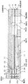
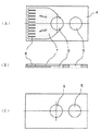
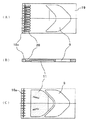
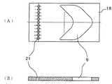
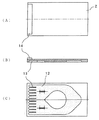
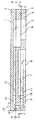
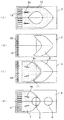
以下、図1〜図6に基づいて、LD冷却用放熱器におけるこの発明の実施の形態を説明する。従来例と対応する部分には同一の符号を用いるものとする。ここで、図1は放熱器の縦断面図、図2の(A)は図1における下部放熱板の上面図、(B)は同じく縦断面図、(C)は同じく下面図、図3は図1における中間放熱板を構成する下板の上面図、(B)は同じく縦断面図、(C)は同じく下面図、図4の(A)は図1における中間放熱板を構成する中板の上面図、(B)は同じく縦断面図、図5の(A)は図1における中間放熱板を構成する上板の上面図、(B)は同じく縦断面図、(C)は同じく下面図、図6の(A)は図1における上部放熱板の上面図、(B)は同じく縦断面図、(C)は同じく下面図である。 Hereinafter, based on FIGS. 1-6, embodiment of this invention in the radiator for LD cooling is described. The same reference numerals are used for portions corresponding to the conventional example. 1 is a longitudinal sectional view of the radiator, FIG. 2A is a top view of the lower radiator plate in FIG. 1, FIG. 1B is a longitudinal sectional view, FIG. 1C is a bottom view, and FIG. FIG. 1B is a longitudinal sectional view, FIG. 4C is a bottom view, and FIG. 4A is a middle plate constituting the intermediate heat sink in FIG. 5B is a longitudinal sectional view, FIG. 5A is a top view of the upper plate constituting the intermediate heat sink in FIG. 1, FIG. 5B is a longitudinal sectional view, and FIG. 6A is a top view of the upper radiator plate in FIG. 1, FIG. 6B is a longitudinal sectional view, and FIG. 6C is a bottom view.
さて、図示実施の形態において、上部放熱板2及び下部放熱板4の構成は図7の従来技術と実質的に同じで、まず図2において、下部放熱板2には中間放熱板3の排水孔5と給水孔6とが設けられ、上面に給水孔6から受熱端部に達する下部水路7が溝状に形成されている。更に、下部放熱板4の受熱端部には、下部水路7中に突出するように、多数の放熱フィン8が櫛歯状に形成されている。次に、図6において、上部放熱板2には連通孔10と排水孔9とに跨るように上部水路12が溝状に形成され、受熱端部には上部水路12中に突出するように、多数の放熱フィン13が下部放熱板4の放熱フィン8と重なるように櫛歯状に形成されている。
In the illustrated embodiment, the configurations of the upper heat sink 2 and the
一方、図1において、中間放熱板3には排水孔5に通じるように排水孔9がV字状(図3参照)に設けられるとともに、受熱端部に下部水路7と重なるように連通孔10が設けられている。更に、中間放熱板3の下面には、下部水路7と対向するように水路11が溝状に形成され、流路断面積の拡大が図られている。ここで、図7の従来技術と相違するのは、中間放熱板3の連通孔10における水入口10aと水出口10bとの間に、コ字状に反転する折返し水路10cが中間放熱板3の板面と平行に形成されている点である。この折返し水路10cは、次に述べるようにして形成されている。
On the other hand, in FIG. 1, a
すなわち、図1において、中間放熱板3は、上板17、中板18及び下板19が上下3層に積層されて構成されている。そして、図3に示すように、下板19には丸孔からなるからなる多数の水入口10aが設けられ、下板19の上面に一端が水入口10aに通じる往水路20が溝状に形成されている。次に、図4に示すように、中板18には下板19における往水路20の他端(図3の右端)に通じる丸孔からなる多数の通水孔21が設けられている。また、図5に示すように、上板17には丸孔からなる多数の水出口10bが設けられ、上板17の下面に一端(図5の左端)が水出口10bに通じ、他端(同右端)が中板18の通水孔21に通じる復水路22が溝状に形成されている。排水孔9は上板17、中板18、下板19に共通にあけられている。
That is, in FIG. 1, the intermediate |
中間放熱板3は上板17、中板18及び下板19が積層されて構成され、折返し水路10cは下板19の往水路20、中板18の通水孔21及び上板17の復水路22が連続することにより形成される。往水路20や復水路22は例えばエッチング加工により形成され、通水孔21は例えばプレス加工により打ち抜かれる。図示の通り、中間放熱板3を3枚の板17〜19に分割し、各板に形成した溝や孔を連続させることにより、複雑な折返し水路も容易に形成することができる。
The intermediate
図1の放熱器1において、冷却水は矢印で示すように、給水孔6から下部水路7を経て連通孔10の水入口10aに入り、反転して折返し水路10cに導入される。ここで、冷却水は往水路20を奥部に進んだ後、通水孔21を通過して反転し、復水路22を戻って水出口10bに達する。この冷却水は反転して上部水路12に入り、排水孔9,5に向かって流れる。このような放熱器1によれば、中間放熱板3の連通孔10に折返し水路10cを形成したことにより、中間放熱板3における受熱端部16での冷却水との接触面積が増え、上部放熱板2から放熱フィン13を通して受熱端部16に伝えられた熱は効果的に冷却水に伝達される結果、放熱器1の冷却効率が大幅に向上する。なお、中間放熱板は3層以上の多層にして折返し水路をジグザグ状に形成し、冷却水の迂回経路を更に長くして冷却効果を一層高めることも可能である。
In the radiator 1 of FIG. 1, the cooling water enters the
1 放熱器
2 上部放熱板
3 中間放熱板
4 下部放熱板
5 排水孔
6 給水孔
7 下部水路
8 放熱フィン
9 排水孔
10 連通孔
10a 水入口
10b 水出口
10c 折返し水路
12 上部水路
13 放熱フィン
14 発熱体
17 上板
18 中板
19 下板
20 往水路
21 通水孔
22 復水路
DESCRIPTION OF SYMBOLS 1 Heat radiator 2
Claims (2)
前記下部放熱板には他端に排水孔が設けられ、かつこの排水孔と前記受熱端部との中間に給水孔が設けられるとともに、上面に前記給水孔から前記受熱端部に達する下部水路が溝状に形成され、
前記中間放熱板には前記下部放熱板の排水孔に通じるように排水孔が設けられるとともに、前記受熱端部に前記下部水路と重なるように連通孔が設けられ、
前記上部放熱板には下面に前記中間放熱板の連通孔と排水孔とに跨るように上部水路が溝状に形成されるとともに、前記受熱端部の上面に発熱体が接合され、
前記給水孔から前記下部水路、前記連通孔及び前記上部水路を通して前記排水孔に流される冷却水により前記発熱体を冷却する放熱器において、
前記中間放熱板の連通孔の水入口と水出口との間に、コ字状に反転する折返し水路を前記中間放熱板の板面と平行に形成し、この迂回通路を流れる前記冷却水により前記中間放熱板の受熱端部を冷却するようにしたことを特徴とする放熱器。 An upper radiator plate, an intermediate radiator plate and a lower radiator plate each having one end as a heat receiving end are laminated in three layers,
The lower radiator plate is provided with a drain hole at the other end, a water supply hole is provided between the drain hole and the heat receiving end, and a lower water channel reaching the heat receiving end from the water supply hole is provided on the upper surface. Formed in a groove shape,
The intermediate radiator plate is provided with a drain hole so as to communicate with the drain hole of the lower radiator plate, and a communication hole is provided so as to overlap the lower water channel at the heat receiving end,
An upper water channel is formed in a groove shape so as to straddle the communication hole and the drainage hole of the intermediate heat dissipation plate on the lower surface of the upper heat dissipation plate, and a heating element is joined to the upper surface of the heat receiving end,
In the radiator that cools the heating element with cooling water that flows from the water supply hole to the drain hole through the lower water channel, the communication hole, and the upper water channel,
Between the water inlet and the water outlet of the communication hole of the intermediate radiator plate, a folded water channel that is inverted in a U-shape is formed in parallel with the plate surface of the intermediate radiator plate, and the cooling water flowing through the bypass passage A heat radiator characterized by cooling the heat receiving end of the intermediate heat sink.
The intermediate heat radiating plate is composed of an upper plate, a middle plate, and a lower plate that are laminated in three upper and lower layers, and the water inlet is provided in the lower plate, and an outlet channel having one end leading to the water inlet is provided on the upper surface of the lower plate. It is formed in the shape of a groove, and the middle plate is provided with a water passage hole that communicates with the other end of the outgoing channel of the lower plate, the water outlet is provided on the upper plate, and one end is provided on the lower surface of the upper plate on the water outlet A condensate channel whose other end communicates with the water hole of the middle plate is formed in a groove shape, and the upper plate, the middle plate, and the lower plate are stacked, so that the lower plate's outgoing channel, the middle plate's water flow The radiator according to claim 1, wherein the folded water channel is formed by continuing a hole and a condensate channel of the upper plate.
Priority Applications (1)
| Application Number | Priority Date | Filing Date | Title |
|---|---|---|---|
| JP2004111660A JP4305253B2 (en) | 2004-04-06 | 2004-04-06 | Radiator |
Applications Claiming Priority (1)
| Application Number | Priority Date | Filing Date | Title |
|---|---|---|---|
| JP2004111660A JP4305253B2 (en) | 2004-04-06 | 2004-04-06 | Radiator |
Publications (2)
| Publication Number | Publication Date |
|---|---|
| JP2005294769A true JP2005294769A (en) | 2005-10-20 |
| JP4305253B2 JP4305253B2 (en) | 2009-07-29 |
Family
ID=35327321
Family Applications (1)
| Application Number | Title | Priority Date | Filing Date |
|---|---|---|---|
| JP2004111660A Expired - Fee Related JP4305253B2 (en) | 2004-04-06 | 2004-04-06 | Radiator |
Country Status (1)
| Country | Link |
|---|---|
| JP (1) | JP4305253B2 (en) |
Cited By (3)
| Publication number | Priority date | Publication date | Assignee | Title |
|---|---|---|---|---|
| DE102008026856A1 (en) * | 2008-06-05 | 2009-12-17 | Jenoptik Laserdiode Gmbh | Cooling element for an electronic component and device with an electronic component |
| CN101882753A (en) * | 2010-06-23 | 2010-11-10 | 中国科学院上海光学精密机械研究所 | High-power laser diode heat sink |
| WO2022038998A1 (en) | 2020-08-19 | 2022-02-24 | パナソニックIpマネジメント株式会社 | Laser module |
Families Citing this family (1)
| Publication number | Priority date | Publication date | Assignee | Title |
|---|---|---|---|---|
| CN109822242A (en) * | 2019-04-01 | 2019-05-31 | 苏州匠恒智造科技有限公司 | A kind of laser process equipment with combined micro-channel radiator |
-
2004
- 2004-04-06 JP JP2004111660A patent/JP4305253B2/en not_active Expired - Fee Related
Cited By (3)
| Publication number | Priority date | Publication date | Assignee | Title |
|---|---|---|---|---|
| DE102008026856A1 (en) * | 2008-06-05 | 2009-12-17 | Jenoptik Laserdiode Gmbh | Cooling element for an electronic component and device with an electronic component |
| CN101882753A (en) * | 2010-06-23 | 2010-11-10 | 中国科学院上海光学精密机械研究所 | High-power laser diode heat sink |
| WO2022038998A1 (en) | 2020-08-19 | 2022-02-24 | パナソニックIpマネジメント株式会社 | Laser module |
Also Published As
| Publication number | Publication date |
|---|---|
| JP4305253B2 (en) | 2009-07-29 |
Similar Documents
| Publication | Publication Date | Title |
|---|---|---|
| US7305016B2 (en) | Laser diode package with an internal fluid cooling channel | |
| US7836943B2 (en) | Normal-flow heat exchanger | |
| US7302998B2 (en) | Normal-flow heat exchanger | |
| WO2015079643A1 (en) | Method of manufacturing cooler for semiconductor module, cooler for semiconductor module, semiconductor module, and electrically driven vehicle | |
| US20030066634A1 (en) | Heat exchanger | |
| JPWO2019009172A1 (en) | Semiconductor laser device | |
| JP2011134979A (en) | Liquid cooling type heat sink | |
| US7204303B2 (en) | Flat tube cold plate assembly | |
| JP2006352019A (en) | Heat sink, laser device having the same, and laser stacking device | |
| JP2010123881A (en) | Cold plate | |
| JP2008041750A (en) | Water-cooling heat sink and water-cooling system | |
| JP2008205371A (en) | Liquid-cooled type cooler and unit for mounting power element | |
| JP4305253B2 (en) | Radiator | |
| JP5589647B2 (en) | Cooling system | |
| JP2011134978A (en) | Fluid cooling type heat sink | |
| JP2005166789A (en) | Heat dissipator | |
| JPH08139478A (en) | Heat sink | |
| JP2005294768A (en) | Heat radiator | |
| JP2006332233A (en) | Heat radiator | |
| JP2005340532A (en) | Radiator | |
| JP4522725B2 (en) | heatsink | |
| JP2005209874A (en) | Heatsink | |
| JP2005203560A (en) | Radiator | |
| JP2007123736A (en) | Radiator | |
| JP2005093614A (en) | Radiator |
Legal Events
| Date | Code | Title | Description |
|---|---|---|---|
| A621 | Written request for application examination |
Free format text: JAPANESE INTERMEDIATE CODE: A621 Effective date: 20061212 |
|
| A977 | Report on retrieval |
Free format text: JAPANESE INTERMEDIATE CODE: A971007 Effective date: 20090306 |
|
| TRDD | Decision of grant or rejection written | ||
| A01 | Written decision to grant a patent or to grant a registration (utility model) |
Free format text: JAPANESE INTERMEDIATE CODE: A01 Effective date: 20090407 |
|
| A01 | Written decision to grant a patent or to grant a registration (utility model) |
Free format text: JAPANESE INTERMEDIATE CODE: A01 |
|
| A61 | First payment of annual fees (during grant procedure) |
Free format text: JAPANESE INTERMEDIATE CODE: A61 Effective date: 20090420 |
|
| R150 | Certificate of patent or registration of utility model |
Ref document number: 4305253 Country of ref document: JP Free format text: JAPANESE INTERMEDIATE CODE: R150 Free format text: JAPANESE INTERMEDIATE CODE: R150 |
|
| FPAY | Renewal fee payment (event date is renewal date of database) |
Free format text: PAYMENT UNTIL: 20120515 Year of fee payment: 3 |
|
| FPAY | Renewal fee payment (event date is renewal date of database) |
Free format text: PAYMENT UNTIL: 20120515 Year of fee payment: 3 |
|
| S111 | Request for change of ownership or part of ownership |
Free format text: JAPANESE INTERMEDIATE CODE: R313111 |
|
| FPAY | Renewal fee payment (event date is renewal date of database) |
Free format text: PAYMENT UNTIL: 20120515 Year of fee payment: 3 |
|
| R350 | Written notification of registration of transfer |
Free format text: JAPANESE INTERMEDIATE CODE: R350 |
|
| FPAY | Renewal fee payment (event date is renewal date of database) |
Free format text: PAYMENT UNTIL: 20120515 Year of fee payment: 3 |
|
| FPAY | Renewal fee payment (event date is renewal date of database) |
Free format text: PAYMENT UNTIL: 20130515 Year of fee payment: 4 |
|
| R250 | Receipt of annual fees |
Free format text: JAPANESE INTERMEDIATE CODE: R250 |
|
| FPAY | Renewal fee payment (event date is renewal date of database) |
Free format text: PAYMENT UNTIL: 20130515 Year of fee payment: 4 |
|
| FPAY | Renewal fee payment (event date is renewal date of database) |
Free format text: PAYMENT UNTIL: 20140515 Year of fee payment: 5 |
|
| R250 | Receipt of annual fees |
Free format text: JAPANESE INTERMEDIATE CODE: R250 |
|
| R250 | Receipt of annual fees |
Free format text: JAPANESE INTERMEDIATE CODE: R250 |
|
| R250 | Receipt of annual fees |
Free format text: JAPANESE INTERMEDIATE CODE: R250 |
|
| R250 | Receipt of annual fees |
Free format text: JAPANESE INTERMEDIATE CODE: R250 |
|
| R250 | Receipt of annual fees |
Free format text: JAPANESE INTERMEDIATE CODE: R250 |
|
| R250 | Receipt of annual fees |
Free format text: JAPANESE INTERMEDIATE CODE: R250 |
|
| R250 | Receipt of annual fees |
Free format text: JAPANESE INTERMEDIATE CODE: R250 |
|
| R250 | Receipt of annual fees |
Free format text: JAPANESE INTERMEDIATE CODE: R250 |
|
| R250 | Receipt of annual fees |
Free format text: JAPANESE INTERMEDIATE CODE: R250 |
|
| R250 | Receipt of annual fees |
Free format text: JAPANESE INTERMEDIATE CODE: R250 |
|
| LAPS | Cancellation because of no payment of annual fees |