JP2005294481A - Printed circuit board connection structure - Google Patents
Printed circuit board connection structure Download PDFInfo
- Publication number
- JP2005294481A JP2005294481A JP2004106555A JP2004106555A JP2005294481A JP 2005294481 A JP2005294481 A JP 2005294481A JP 2004106555 A JP2004106555 A JP 2004106555A JP 2004106555 A JP2004106555 A JP 2004106555A JP 2005294481 A JP2005294481 A JP 2005294481A
- Authority
- JP
- Japan
- Prior art keywords
- brake
- wheel
- printed wiring
- wiring board
- hydraulic pressure
- Prior art date
- Legal status (The legal status is an assumption and is not a legal conclusion. Google has not performed a legal analysis and makes no representation as to the accuracy of the status listed.)
- Pending
Links
Images


Landscapes
- Coupling Device And Connection With Printed Circuit (AREA)
- Combinations Of Printed Boards (AREA)
- Regulating Braking Force (AREA)
- Multi-Conductor Connections (AREA)
Abstract
Description
本発明は、はんだのだれを抑止することができるプリント配線基板の接続構造に関する。 The present invention relates to a printed wiring board connection structure that can suppress solder drooling.
一般に、種々の部品等がはんだ付けされて接続されるプリント配線基板は、各種製品において幅広く使用されている。例えば、車両用ブレーキ液圧制御装置に用いられるプリント配線基板では、直線状に間隔を隔てたランドが複数点在され、各ランドに対し、基板に実装する部品の端子部材がはんだ付けされて接続されたものが開示されている(例えば、特許文献1,2参照)。
このようなプリント配線基板の接続構造においては、前記端子部材がプリント配線基板の下面側からスルーホールに挿入され、上面側に引き出された状態で、上面側から端子部材とランドとをはんだ付けしていた。
In such a printed wiring board connection structure, the terminal member and the land are soldered from the upper surface side in a state where the terminal member is inserted into the through hole from the lower surface side of the printed wiring board and pulled out to the upper surface side. It was.
前記従来のプリント配線基板の接続構造では、はんだ付けの際に溶融したはんだが、ランドからスルーホールの端子部材を伝わって下へ流れるというだれを生じるおそれがあった。このようなはんだのだれは、例えば、ランドに供給されるはんだの量やこて先の温度等を管理してこれらを所定の値に保持することにより抑止することがある程度は可能であるが、煩雑であるという問題があった。 In the conventional printed wiring board connection structure, the solder melted during soldering may flow down from the land through the terminal member of the through hole, and there is a risk of causing drool. Such solder dripping can be suppressed to some extent by controlling the amount of solder supplied to the land, the temperature of the tip, etc., and holding them at a predetermined value, but is complicated. There was a problem of being.
そこで、本発明では、簡単な構造によりはんだのだれを抑止することができるプリント配線基板の接続構造を提供することを目的とする。 Therefore, an object of the present invention is to provide a printed wiring board connection structure that can suppress solder dripping with a simple structure.
前記課題を解決するため、スルーホールを有するランドが設けられたプリント配線基板と、このプリント配線基板の前記ランドの前記スルーホールに、前記プリント配線基板の下面側からはんだ付け面となる上面側へ向けて貫通され、前記ランドに対してはんだ付けされる端子部材とを含むプリント配線基板の接続構造であって、前記端子部材は、前記スルーホールに貫通する貫通部と、この貫通部の下方部位に形成され、前記貫通部よりも幅広とされた幅広部とを有し、前記幅広部は、前記貫通部を前記プリント配線基板の前記スルーホールに貫通させた状態で、前記スルーホールよりも下方に位置し、はんだが前記貫通部を伝わって下方へ流れ落ちるのを抑止することを特徴とする。 In order to solve the above problems, a printed wiring board provided with a land having a through hole and the through hole of the land of the printed wiring board from the lower surface side of the printed wiring board to the upper surface side serving as a soldering surface. A printed wiring board connection structure including a terminal member that penetrates toward the land and is soldered to the land, wherein the terminal member includes a through portion that penetrates the through hole, and a lower portion of the through portion. A wide portion that is wider than the through portion, and the wide portion is lower than the through hole in a state where the through portion penetrates the through hole of the printed wiring board. And the solder is prevented from flowing down through the penetrating portion.
このようなプリント配線基板の接続構造によれば、端子部材を伝わって流れ落ちるはんだが仮に生じても、流れ落ちたはんだは、貫通部の下方部位に形成され、スルーホールよりも下方に位置する幅広部により受け止められることとなり、幅広部で凝固するようになる。これにより、溶融したはんだが端子部材の下方に流れるというだれが抑止される。したがって、端子部材に対して幅広部を設けるという簡単な構造により、はんだのだれを抑止することができる。 According to such a printed wiring board connection structure, even if solder that flows down through the terminal member is generated, the solder that has flowed down is formed in the lower portion of the through portion, and is a wide portion positioned below the through hole. Will be solidified at the wide part. This prevents any molten solder from flowing under the terminal member. Therefore, dripping of solder can be suppressed by a simple structure in which the wide portion is provided to the terminal member.
また、前記した幅広部は、段部をもって形成されることが望ましい。
さらに、前記した幅広部は、端子部材の軸芯へ向けて下り傾斜状のはんだ受け面を有することが望ましい。
幅広部にこのような段部またははんだ受け面があれば、流れてきたはんだの保持性が高まるようになる。これにより、はんだ付けの際に溶融したはんだが端子部材の下方に流れるというだれをより一層効果的に抑止することができる。
Moreover, it is desirable that the above-described wide portion is formed with a stepped portion.
Furthermore, it is desirable that the wide portion described above has a solder receiving surface that is inclined downward toward the axis of the terminal member.
If such a stepped portion or a solder receiving surface is provided in the wide portion, the retainability of the flowing solder is improved. Thereby, it can suppress more effectively that the solder which fuse | melted in the case of soldering flows below a terminal member.
本発明のプリント配線基板の接続構造によれば、簡単な構造によりはんだのだれを抑止することができる。 According to the printed wiring board connection structure of the present invention, it is possible to suppress dripping of solder with a simple structure.
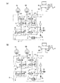
以下、本発明を実施するための最良の形態を、添付した図面を参照しつつ詳細に説明する。参照する図面において、図1は本発明の一実施の形態のプリント配線基板の接続構造が適用される車両用ブレーキ液圧制御装置のブレーキ液圧回路図であり、図2はアンチロックブレーキ制御時における車両用ブレーキ液圧制御装置の状態を示すブレーキ液圧回路図であって、(a)は車輪ブレーキに作用するブレーキ液圧を減圧する場合を示す図、(b)は車輪ブレーキに作用するブレーキ液圧を一定に保持する場合を示す図である。また、図3は非ペダル操作時のブレーキ制御時における車両用ブレーキ液圧制御装置の状態を示すブレーキ液圧回路図である。なお、非ペダル操作時とは、ブレーキペダルを操作していない状態を言う。 Hereinafter, the best mode for carrying out the present invention will be described in detail with reference to the accompanying drawings. In the drawings to be referred to, FIG. 1 is a brake hydraulic circuit diagram of a vehicle brake hydraulic pressure control device to which a printed wiring board connection structure according to an embodiment of the present invention is applied, and FIG. FIG. 2 is a brake fluid pressure circuit diagram showing the state of the vehicle brake fluid pressure control device in FIG. 1, (a) is a diagram showing a case where the brake fluid pressure acting on the wheel brake is reduced, and (b) is acted on the wheel brake. It is a figure which shows the case where a brake fluid pressure is kept constant. FIG. 3 is a brake fluid pressure circuit diagram showing the state of the vehicle brake fluid pressure control device during brake control during non-pedal operation. The non-pedal operation means a state where the brake pedal is not operated.
図1に示すように、車両用ブレーキ液圧制御装置Sは、運転者がブレーキペダルPに加える踏力に応じたブレーキ液圧を発生するマスタシリンダMと、車輪ブレーキFL,RR,RL,FRとの間に配置されている。マスタシリンダMの二つの出力ポートM1,M2は、後記するポンプボディ100の入口ポート121に接続され、ポンプボディ100の出口ポート122が、各車輪ブレーキFL,RR,RL,FRに接続されている。そして、通常時は車両用ブレーキ液圧制御装置S内の入口ポート121から出口ポート122までが連通した油路となっていることで、ブレーキペダルPの踏力が各車輪ブレーキFL,RR,RL,FRに伝達されるようになっている。
As shown in FIG. 1, the vehicle brake fluid pressure control device S includes a master cylinder M that generates brake fluid pressure corresponding to the pedaling force applied by the driver to the brake pedal P, wheel brakes FL, RR, RL, and FR. It is arranged between. Two output ports M1, M2 of the master cylinder M are connected to an
ここで、出力ポートM1から始まる油路は、前輪左側の車輪ブレーキFLと後輪右側の車輪ブレーキRRに通じており、出力ポートM2から始まる油路は、前輪右側の車輪ブレーキFRと後輪左側の車輪ブレーキRLに通じている。なお、以下では、出力ポートM1から始まる油路を「第一系統」と称し、出力ポートM2から始まる油路を「第二系統」と称する。 Here, the oil path starting from the output port M1 leads to the wheel brake FL on the left side of the front wheel and the wheel brake RR on the right side of the rear wheel, and the oil path starting from the output port M2 is set to the wheel brake FR on the right side of the front wheel and the left side of the rear wheel. To the wheel brake RL. Hereinafter, the oil passage starting from the output port M1 is referred to as “first system”, and the oil passage starting from the output port M2 is referred to as “second system”.
車両用ブレーキ液圧制御装置Sには、その第一系統に各車輪ブレーキFL,RRに対応して二つの制御弁手段Vが設けられており、同様に、その第二系統に各車輪ブレーキRL,FRに対応して二つの制御弁手段Vが設けられている。また、この車両用ブレーキ液圧制御装置Sには、第一系統および第二系統のそれぞれに、リザーバ3、ポンプ4、ダンパ5、オリフィス5a、レギュレータR、吸入弁7、貯留室7aが設けられており、さらに、第一系統のポンプ4と第二系統のポンプ4とを駆動するための共通の電動モータ20を備えている。また、本実施形態では、第二系統にのみ圧力センサ8が設けられている。
The vehicle brake hydraulic pressure control device S is provided with two control valve means V corresponding to each wheel brake FL, RR in the first system, and similarly, each wheel brake RL in the second system. , FR, two control valve means V are provided. The vehicle brake fluid pressure control device S is provided with a
なお、以下では、マスタシリンダMの出力ポートM1,M2から各レギュレータRに至る油路を「出力液圧路A」と称し、第一系統のレギュレータRから車輪ブレーキFL,RRに至る油路および第二系統のレギュレータRから車輪ブレーキRL,FRに至る油路をそれぞれ「車輪液圧路B」と称する。また、出力液圧路Aからポンプ4に至る油路を「吸入液圧路C」と称し、ポンプ4から車輪液圧路Bに至る油路を「吐出液圧路D」と称し、さらに、車輪液圧路Bから吸入液圧路Cに至る油路を「解放路E」と称する。 In the following, the oil passage from the output ports M1, M2 of the master cylinder M to each regulator R is referred to as “output hydraulic pressure passage A”, and the oil passage from the first system regulator R to the wheel brakes FL, RR and The oil passages from the second system regulator R to the wheel brakes RL and FR are respectively referred to as “wheel hydraulic pressure passage B”. In addition, an oil path from the output hydraulic pressure path A to the pump 4 is referred to as “suction hydraulic pressure path C”, an oil path from the pump 4 to the wheel hydraulic pressure path B is referred to as “discharge hydraulic pressure path D”, and The oil path from the wheel hydraulic pressure path B to the suction hydraulic pressure path C is referred to as “release path E”.
制御弁手段Vは、車輪液圧路Bを開放しつつ解放路Eを遮断する状態、車輪液圧路Bを遮断しつつ解放路Eを開放する状態および車輪液圧路Bを遮断しつつ解放路Eを遮断する状態を切り換える機能を有しており、入口弁1、出口弁2、チェック弁1aを備えて構成されている。
The control valve means V opens the wheel hydraulic pressure path B while blocking the release path E, blocks the wheel hydraulic pressure path B while opening the release path E, and blocks the wheel hydraulic pressure path B and releases it. It has a function of switching the state of shutting off the path E, and includes an
入口弁1は、車輪液圧路Bに設けられた常開型の電磁弁である。入口弁1は、通常時に開いていることで、マスタシリンダMから各車輪ブレーキFL,RR,RL,FRへブレーキ液圧が伝達するのを許容している。また、入口弁1は、車輪がロックしそうになったときに図示せぬ制御装置により閉塞されることで、ブレーキペダルPから各車輪ブレーキFL,RR,RL,FRに伝達するブレーキ液圧を遮断する。
The
出口弁2は、車輪液圧路Bと解放路Eとの間に介設された常閉型の弁である。出口弁2は、通常時に閉塞されているが、車輪がロックしそうになったときに図示せぬ制御装置により開放されることで、各車輪ブレーキFL,RR,RL,FRに作用するブレーキ液圧を各リザーバ3に逃がす。
The
チェック弁1aは、各入口弁1に並列に接続されている。このチェック弁1aは、各車輪ブレーキFL,RR,RL,FR側からマスタシリンダM側へのブレーキ液の流入のみを許容する弁であり、入口弁1および出口弁2の両方を閉じた状態にしたときにおいても各車輪ブレーキFL,RR,RL,FR側のブレーキ液圧が所定圧以上であれば、各車輪ブレーキFL,RR,RL,FR側からマスタシリンダM側へのブレーキ液の流入を許容する。
The
リザーバ3は、解放路Eに設けられており、各出口弁2が開放されることによって逃がされるブレーキ液圧を吸収する機能を有している。
The
ポンプ4は、出力液圧路Aに通じる吸入液圧路Cと車輪液圧路Bに通じる吐出液圧路Dとの間に介設されており、リザーバ3で貯留されているブレーキ液を吸入して吐出液圧路Dに吐出する機能を有している。これにより、リザーバ3によるブレーキ液圧の吸収によって減圧された出力液圧路Aや車輪液圧路Bの圧力状態が回復される。さらに、このポンプ4は、後記するカット弁6が出力液圧路Aから車輪液圧路Bへのブレーキ液の流入を遮断し、且つ、後記する吸入弁7が吸入液圧路Cを開放しているときに、マスタシリンダM、出力液圧路A、吸入液圧路Cおよび貯留室7aに貯留されているブレーキ液を吸入して吐出液圧路Dに吐出する機能を有している。これにより、非ペダル操作時において各車輪ブレーキFL,RR,RL,FRにブレーキ液圧を作用させることが可能となる。
The pump 4 is interposed between the suction hydraulic pressure path C leading to the output hydraulic pressure path A and the discharge hydraulic pressure path D leading to the wheel hydraulic pressure path B, and sucks the brake fluid stored in the
なお、ダンパ5およびオリフィス5aは、その協働作用によってポンプ4から吐出されたブレーキ液の圧力の脈動および後記するレギュレータRが作動することにより発生する脈動を減衰させている。
The damper 5 and the
レギュレータRは、出力液圧路Aから車輪液圧路Bへのブレーキ液の流入を許容する状態および遮断する状態を切り換える機能と、出力液圧路Aから車輪液圧路Bへのブレーキ液の流入が遮断されているときに車輪液圧路Bおよび吐出液圧路Dのブレーキ液圧を設定値以下に調節する機能とを有しており、カット弁6、チェック弁6aおよびリリーフ弁6bを備えて構成されている。
The regulator R has a function of switching between a state where the brake fluid is allowed to flow from the output hydraulic pressure passage A to the wheel hydraulic pressure passage B and a state where the brake fluid is blocked, and a brake fluid flow from the output hydraulic pressure passage A to the wheel hydraulic pressure passage B. It has a function of adjusting the brake fluid pressure in the wheel fluid pressure passage B and the discharge fluid pressure passage D to a set value or less when the inflow is cut off, and the cut valve 6, the
カット弁6は、マスタシリンダMに通じる出力液圧路Aと各車輪ブレーキFL,RR,RL,FRに通じる車輪液圧路Bとの間に介設された常開型の電磁弁であり、出力液圧路Aから車輪液圧路Bへのブレーキ液の流入を許容する状態および遮断する状態を切り換えるものである。カット弁6は、通常時に開いていることで、マスタシリンダMから各車輪ブレーキFL,RR,RL,FRへブレーキ液圧が伝達するのを許容している。また、カット弁6は、非ペダル操作時であってポンプ4を作動させるとき、言い換えれば、非ペダル操作時において各車輪ブレーキFL,RR,RL,FRにブレーキ液圧を作用させるときに図示せぬ制御装置により閉塞される。 The cut valve 6 is a normally-open electromagnetic valve interposed between the output hydraulic pressure path A leading to the master cylinder M and the wheel hydraulic pressure path B leading to each wheel brake FL, RR, RL, FR. The state in which the inflow of the brake fluid from the output hydraulic pressure path A to the wheel hydraulic pressure path B is permitted and the state in which the brake fluid is blocked are switched. The cut valve 6 is normally open, thereby allowing the brake hydraulic pressure to be transmitted from the master cylinder M to the wheel brakes FL, RR, RL, FR. The cut valve 6 is not illustrated when the pump 4 is operated when the pedal is not operated, in other words, when the brake fluid pressure is applied to the wheel brakes FL, RR, RL, and FR when the pedal is not operated. It is blocked by the control device.
チェック弁6aは、各カット弁6に並列に接続されている。このチェック弁6aは、出力液圧路Aから車輪液圧路Bへのブレーキ液の流入のみを許容する弁であり、各カット弁6を閉じた状態にしたときにおいても、出力液圧路A側のブレーキ液圧が所定圧以上であれば、出力液圧路Aから車輪液圧路Bへのブレーキ液の流入を許容する。
The
リリーフ弁6bは、各カット弁6に並列に接続されており、車輪液圧路Bおよび吐出液圧路Dのブレーキ液圧が設定値以上になるのに応じて開弁する。
The
吸入弁7は、吸入液圧路Cに設けられた常閉型の電磁弁であり、吸入液圧路Cを開放する状態および遮断する状態を切り換えるものである。吸入弁7は、非ペダル操作時であってカット弁6が出力液圧路Aから車輪液圧路Bへのブレーキ液の流入を遮断する状態にあるとき、言い換えれば、非ペダル操作時において各車輪ブレーキFL,RR,RL,FRにブレーキ液圧を作用させるときに図示せぬ制御装置により開放(開弁)される。
The
貯留室7aは、吸入液圧路Cであってポンプ4と吸入弁7との間に設けられている。この貯留室7aは、ブレーキ液を貯留するものであり、これにより、吸入液圧路Cに貯留されるブレーキ液の容量が実質的に増大する。
The
圧力センサ8は、出力液圧路Aのブレーキ液圧を計測するものであり、その計測結果は図示せぬ制御装置に随時取り込まれ、かかる制御装置によりマスタシリンダMからブレーキ液圧が出力されているか否か、すなわち、ブレーキペダルPが踏まれているか否かが判定され、さらに、圧力センサ8で計測されたブレーキ液圧の大きさに基づいて、車両の横滑り制御、トラクション制御などが行われる。
The
次に、車両用ブレーキ液圧制御装置Sの動作を、図1乃至図3を参照して詳細に説明する。なお、図2および図3では、簡単のため、第一系統のみを図示しているが、第二系統の場合も同様である。 Next, the operation of the vehicle brake hydraulic pressure control device S will be described in detail with reference to FIGS. 2 and 3, only the first system is shown for simplicity, but the same applies to the second system.
(通常時)
各車輪がロックする可能性のない通常のブレーキ時(通常時)においては、図1に示すように、レギュレータRは出力液圧路Aから車輪液圧路Bへのブレーキ液の流入を許容する状態にあり、吸入弁7は吸入液圧路Cを遮断する状態にあり、制御弁手段Vは車輪液圧路Bを開放しつつ解放路Eを遮断する状態にある。つまり、レギュレータRのカット弁6と制御弁手段Vの入口弁1とが開放(開弁)状態にあり、吸入弁7と制御弁手段Vの出口弁2とが閉塞(閉弁)状態にある。したがって、ブレーキペダルPの踏力に起因して発生したブレーキ液圧は、そのまま車輪ブレーキFL,RR,RL,FRに作用する。なお、入口弁1およびカット弁6が常開型の電磁弁であり、出口弁2および吸入弁7が常閉型の電磁弁であるから、通常時においては、総ての電磁弁が消磁された状態にある。
(Normal time)
At the time of normal braking (normal time) where each wheel is not likely to lock, the regulator R allows the brake fluid to flow from the output hydraulic pressure path A to the wheel hydraulic pressure path B as shown in FIG. In this state, the
(アンチロックブレーキ制御)
ブレーキペダルPを踏み込んでいる最中に、車輪がロック状態に入りそうになると、図示せぬ制御装置によりアンチロックブレーキ制御が開始される。ここで、アンチロックブレーキ制御とは、ロック状態に入りそうな車輪の車輪ブレーキに対応する制御弁手段Vを制御して、車輪ブレーキに作用するブレーキ液圧を減圧、増圧あるいは一定に保持することをいう。なお、アンチロックブレーキ制御時においても、図2(a)に示すように、レギュレータRは出力液圧路Aから車輪液圧路Bへのブレーキ液の流入を許容する状態にあり、吸入弁7は吸入液圧路Cを遮断する状態にある。
(Anti-lock brake control)
If the wheel is about to enter a locked state while the brake pedal P is being depressed, anti-lock brake control is started by a control device (not shown). Here, the anti-lock brake control means that the control valve means V corresponding to the wheel brake of the wheel which is likely to enter the locked state is controlled, and the brake fluid pressure acting on the wheel brake is reduced, increased or kept constant. That means. Even during the anti-lock brake control, as shown in FIG. 2A, the regulator R is in a state of allowing the brake fluid to flow from the output hydraulic pressure passage A to the wheel hydraulic pressure passage B, and the
以下では、左前側の車輪(車輪ブレーキFLにより制動される車輪)がロック状態に入りそうになっていると想定してアンチロックブレーキ制御時における制御弁手段Vの動作を説明する。 In the following, the operation of the control valve means V during antilock brake control will be described on the assumption that the left front wheel (wheel braked by the wheel brake FL) is about to enter the locked state.
車輪ブレーキFLに作用するブレーキ液圧を減圧する場合には、図2(a)に示すように、車輪ブレーキFLに対応する制御弁手段Vにより車輪液圧路Bが遮断され、解放路Eが開放される。つまり、図示せぬ制御装置により入口弁1を励磁して閉塞(閉弁)状態にするとともに、出口弁2を励磁して開放(開弁)状態にする。このようにすると、車輪ブレーキFLに通じる車輪液圧路Bのブレーキ液が解放路Eを通ってリザーバ3に流入し、その結果、車輪ブレーキFLに作用していたブレーキ液圧が減圧される。
When the brake hydraulic pressure acting on the wheel brake FL is reduced, as shown in FIG. 2A, the wheel hydraulic pressure path B is shut off by the control valve means V corresponding to the wheel brake FL, and the release path E is Opened. That is, the
車輪ブレーキFLに作用するブレーキ液圧を一定に保持する場合は、図2(b)に示すように、車輪ブレーキFLに対応する制御弁手段Vにより車輪液圧路Bおよび解放路Eがそれぞれ遮断される。つまり、図示せぬ制御装置により入口弁1を励磁して閉塞(閉弁)状態にするとともに、出口弁2を消磁して閉塞(閉弁)状態にする。このようにすると、車輪ブレーキFL、入口弁1、出口弁2で閉じられた油路内にブレーキ液が閉じ込められることになり、その結果、車輪ブレーキFLに作用していたブレーキ液圧が一定に保持される。
When the brake fluid pressure acting on the wheel brake FL is kept constant, as shown in FIG. 2 (b), the wheel fluid pressure path B and the release path E are cut off by the control valve means V corresponding to the wheel brake FL, respectively. Is done. That is, the
車輪ブレーキFLに作用するブレーキ液圧を増圧する場合は、車輪ブレーキFLに対応する制御弁手段Vにより車輪液圧路Bが解放され、解放路Eが遮断される。つまり、図示せぬ制御装置により入口弁1を消磁して開放(開弁)状態にするとともに、出口弁2を消磁して閉塞(閉弁)状態にする(図1参照)。このようにすると、ブレーキペダルPの踏力に起因して発生したブレーキ液圧が車輪ブレーキFLに直接作用することになり、その結果、車輪ブレーキFLに作用するブレーキ液圧が増圧される。
When the brake hydraulic pressure acting on the wheel brake FL is increased, the wheel hydraulic pressure path B is released and the release path E is blocked by the control valve means V corresponding to the wheel brake FL. That is, the
なお、アンチロックブレーキ制御中は、電動モータ20が駆動し、これに伴ってポンプ4が作動する。これにより、リザーバ3に貯留されたブレーキ液が吐出液圧路Dを介して車輪液圧路Bに還流される。また、ポンプ4が作動することにより吐出液圧路D等に発生する脈動は、ダンパ5およびオリフィス5aの協働作用によって吸収・抑制されるので、ポンプ4を作動させてもブレーキペダルPの操作フィーリングが阻害されることもない。
During the antilock brake control, the
(非ペダル操作時におけるブレーキ制御)
非ペダル操作時においては、車両の状態に応じて、図示せぬ制御装置により、横滑り制御やトラクション制御が開始される。なお、ここでは、非ペダル操作時に左前側の車輪(車輪ブレーキFLにより制動される車輪)を制動させる場合を想定して車両用ブレーキ液圧制御装置Sの動作を説明する。
(Brake control during non-pedal operation)
During non-pedal operation, skid control and traction control are started by a control device (not shown) according to the state of the vehicle. Here, the operation of the vehicle brake hydraulic pressure control device S will be described on the assumption that the left front wheel (the wheel braked by the wheel brake FL) is braked during non-pedal operation.
非ペダル操作時において左前側の車輪を制動する場合は、図3に示すように、レギュレータRにより出力液圧路Aから車輪液圧路Bへのブレーキ液の流入が遮断されるとともに、吸入弁7により吸入液圧路Cが解放され、さらに、車輪ブレーキFLに対応する制御弁手段Vにより車輪ブレーキFLに通じる車輪液圧路Bが開放され、かかる状態においてポンプ4によりマスタシリンダM、出力液圧路A、吸入液圧路Cおよび貯留室7aに貯留されているブレーキ液が吐出液圧路Dに吐出される。つまり、図示せぬ制御装置によりカット弁6が励磁されて閉塞(閉弁)状態にされ、吸入弁7が励磁されて開放(開弁)状態にされ、さらに、制動したい車輪に対応する制御弁手段V以外の制御弁手段Vにおいて入口弁が励磁されて閉塞(閉弁)状態にされ、かかる状態において、ポンプ4を作動させるべく電動モータ20が駆動させられる。そして、ポンプ4により吐出液圧路Dに供給されたブレーキ液は、カット弁6が閉塞状態にされているが故に、車輪ブレーキFLに通じる車輪液圧路Bのみに流入し、その結果、車輪ブレーキFLにブレーキ液圧が作用し、左前側の車輪が制動されることになる。
When braking the left front wheel during non-pedal operation, as shown in FIG. 3, the inflow of brake fluid from the output hydraulic pressure path A to the wheel hydraulic pressure path B is blocked by the regulator R, and the
このとき、貯留室7aにより吸入液圧路Cの容量が実質的に増大しているので、ポンプ4の始動時であっても安定的にブレーキ液を車輪液圧路Bに供給することが可能となる。
At this time, since the capacity of the suction fluid pressure passage C is substantially increased by the
なお、非ペダル操作時におけるブレーキ制御により、車輪液圧路Bおよび吐出液圧路Dのブレーキ液圧が設定値以上になった場合には、リリーフ弁6bの働きにより車輪液圧路Bおよび吐出液圧路D内のブレーキ液が出力液圧路Aに逃がされ、その結果、車輪ブレーキFLに過剰なブレーキ液圧が作用することが回避される。
When the brake fluid pressure in the wheel fluid pressure passage B and the discharge fluid pressure passage D exceeds a set value due to brake control during non-pedal operation, the
また、レギュレータRが作動することによって吐出液圧路D等に発生する脈動は、ダンパ5およびオリフィス5aの協働作用によって吸収・抑制されるので、当該脈動に起因する作動音も小さくなる。
Further, since the pulsation generated in the discharge hydraulic pressure path D and the like by the operation of the regulator R is absorbed and suppressed by the cooperative action of the damper 5 and the
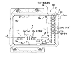
次に、車両用ブレーキ液圧制御装置Sの具体的な構造を、図4および図5を参照して詳細に説明する。
参照する図面において、図4は本発明に係る車両用ブレーキ液圧制御装置の分解斜視図であり、図5は本発明に係る車両用ブレーキ液圧制御装置の分解断面図である。
Next, a specific structure of the vehicle brake hydraulic pressure control device S will be described in detail with reference to FIGS. 4 and 5.
In the drawings to be referred to, FIG. 4 is an exploded perspective view of the vehicle brake hydraulic pressure control device according to the present invention, and FIG. 5 is an exploded cross-sectional view of the vehicle brake hydraulic pressure control device according to the present invention.
図4に示すように、車両用ブレーキ液圧制御装置Sは、各種部材・機器の基体となるポンプボディ(基体)100と、ポンプボディ100の第一取付面101に一体に固着され、電子制御ユニット14(制御装置)などが収容されるコントロールハウジング10と、ポンプボディ100の第二取付面102に一体に固着され、ブレーキ液を送るポンプ4(図1参照)の動力となる電動モータ20とを主に備えている。
As shown in FIG. 4, the vehicle brake hydraulic pressure control device S is integrally fixed to a pump body (base body) 100 serving as a base body of various members and devices and a first mounting
コントロールハウジング10は、電子制御ユニット14(以下、プリント配線基板14と称す)などとの端子部材(端子部材群15A,15B)が埋設された支持板部11を備えるコントロールケース10Aと、このコントロールケース10Aのプリント配線基板14側の開口部を密閉するコントロールカバー10Bとを備えており、ポンプボディ100の第一取付面101にシール部材10Cを介して取り付けられることによって、その内部にプリント配線基板14などを収容するための密閉された部屋(容積の大きな部屋)R1が形成される。なお、図5に示すように、支持板部11のポンプボディ100側の面には、電磁弁を駆動させるための電磁コイル12が取り付けられている。なお、図4においては、端子部材群15A,15Bの各端子部材15a,15bは、簡略した形状で表しており、後記する図8,図9(a−1),(a−2)を用いた説明の欄で詳細に説明する。
The
電動モータ20は、モータケース21、モータカバー22およびロータ23を主に備えている。モータケース21は、略有底円筒状に形成された部材であり、その開口部にモータカバー22が覆設されることによって、その内部にロータ23を収容するための部屋(容積の大きな部屋)R2が形成される。また、ロータ23の出力軸23aは、モータケース21の底部に固定されるボールベアリング24と、モータカバー22に固定されるボールベアリング25と、ポンプボディ100のモータ穴132に固定されるボールベアリング26とにより回転自在に支持されている。そして、この出力軸23aの適所(ボールベアリング25,26の間に位置する部分)には、偏心軸部27が設けられ、偏心軸部27には、ポンプ4のプランジャを往復動させるために、その外周面でプランジャを適宜押圧するボールベアリング28が設けられている。
The
なお、前記したモータケース21とモータカバー22とで形成される部屋R2は、モータケース21とモータカバー22の接触部分の微細な隙間や出力軸23aを支持するボールベアリング25の隙間を介して外部と連通しているが、モータケース21とモータカバー22との間およびモータカバー22とポンプボディ100の第二取付面102との間に図示せぬシール部材が介設されるので、外部とは遮断された(密閉された)状態となっている。
The chamber R2 formed by the
また、ロータ23に電力を供給するためのモータ接続端子23bは、ポンプボディ100の下部に形成された貫通孔131に挿入され、その先端部分がコントロールハウジング10のバスバー13を介してプリント配線基板14に接続される。すなわち、この貫通孔131によって、コントロールハウジング10内の部屋R1と、モータケース21内の部屋R2とが連通する。また、この貫通孔131の適所には、貫通孔131と外部とに連通する段状の通気孔133が形成され、この通気孔133には、通気防水部材Gが設けられている。ここで、通気防水部材Gは、外部からの水の浸入を阻止し、かつ空気の出入りのみを許容する部材であり、例えば周知であるゴアテックス(登録商標)などを通気防水部材Gとして採用することができる。
A
ポンプボディ100は、略直方体に形成される金属部品であり、その各面には電磁弁などの各種機器を設置するための穴(孔)が適宜形成されており、その内部にはブレーキ液の通り道となる油路が適宜形成されている。なお、本実施形態では、ポンプボディ100の左半分で前記した第一系統が構築され、右半分で第二系統が構築される。
The
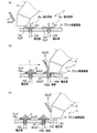
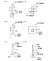
図6は本発明の一実施の形態のプリント配線基板の接続構造が適用されるプリント配線基板14の正面図、図7はコントロールケース10Aにプリント配線基板14が収納された状態を示す正面図、図8は図7のD−D線一部断面図である。また、図9はプリント配線基板の接続構造に用いられる端子部材を示した図であり、(a−1)は要部の斜視図、(a−2)は図9(a−1)のa−a線拡大断面図、(b)〜(c)ははんだ付けの様子を示す模式断面図である。
図6,図7に示すように、プリント配線基板14は、図示しない電子部品が搭載され、コントロールケース10A(図7参照)に収納可能な長方形状に形成されており、コントロールケース10Aの支持板部11(図4参照)に一体に立設された4つの支持ボス11aに、各係合孔14cを係合させることにより固定的に支持される(図5参照)。
プリント配線基板14には、コントロールケース10Aに設けられた端子部材群15A,15B(図4参照)に対応したスルーホールTHを有する直線状のランド群14A,14Bが設けられ、これらの各ランド14a,14bに、前記端子部材群15A,15Bの各端子部材15a,15bが貫通されてはんだ付けされるようになっている。各ランド14a,14bは、プリント配線基板14の両面にスルーホールTHを介して形成される導電部分を有している(図9(b)参照)。
6 is a front view of a printed
As shown in FIGS. 6 and 7, the printed
The printed
各端子部材15a,15bは、図8に示すように(図8では端子部材15bのみ図示)貫通部151と、この貫通部151の下部に形成された幅広部152とを有している。
貫通部151は、図9(a−1),(a−2)、図9(b)に示すように、先端部分が各ランド14a,14b(図9(b)においてランド14aのみ図示)のスルーホールTHに挿入し易い先細り形状となっており、プリント配線基板14の上面側に、はんだ付け可能に突出するようになっている。
幅広部152は、段部152aにより貫通部151よりも幅広に形成されており、はんだ付け時において、はんだが前記貫通部151を伝わって下方へ流れ落ちるのを抑止する機能を有している。すなわち、図9(c)に示すように、はんだ付け時に、貫通部151を伝わって流れ落ちるはんだH1が生じたときでも、図9(d)に示すように、流れ落ちたはんだH1は、幅広部152の段部152aで保持されて、凝固されることとなる。なお、本実施形態では、コントロールケース10Aにプリント配線基板14が組み込まれた状態で、幅広部152(段部152a)が、プリント配線基板14の下面14dよりも間隔を隔てて下方に位置するようになっている(図9(b)参照)。なお、幅広部152は、具体的には、貫通部151よりも0.5mm以上、好ましくは、0.8〜1.5mm程度幅広に形成される。
図8に示すように、幅広部152は、コントロールケース10Aの支持板部11に埋設され、図示しない基端側が前記圧力センサ8や電磁コイル12の図示しない端子等に接続されている。
As shown in FIG. 8 (only the
As shown in FIGS. 9 (a-1), (a-2), and FIG. 9 (b), the penetrating
The
As shown in FIG. 8, the
次に、このようなプリント配線基板14における各ランド14a,14bと各端子部材15a,15bとのはんだ付けについて説明する。
本実施形態では、図示しないはんだ付け装置を利用して、引きはんだによる端子部材群15A,15B(図4参照)ごとのはんだ付けを行う。ここで、端子部材群15Aの端子部材15aにおいては、図7に示すように、縦方向直線状のランド列L1,L2,L3ごとに図中矢印Y方向へ後記するこて先K(図10各図)を移動してはんだ付けを行う。また、端子部材群15Bの端子部材15bにおいては、横方向直線状のランド列L4,L5,L6ごとに図中矢印X方向へ後記するこて先K(図10各図)を移動してはんだ付けを行う。ここで、列ごとのはんだ付けの順序は、任意に設定可能であり、また、こて先Kの温度、移動速度、供給されるはんだHの量は、良好なはんだ付けを行うことのできる所定の値に制御される。
Next, soldering between the
In the present embodiment, soldering is performed for each of the
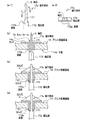
図10(a)〜(c)は、はんだ付けが行われる様子を模式的に示した図である。初めに、図示しないはんだ付け装置の所定の位置に、プリント配線基板14を取り付けた状態のコントロールケース10A(図7参照)を配置する。そうすると、図10(a)に示すように、図示しないアームが操作されて、こて先Kが所定のランド列、ここでは、ランド列L1の先頭に近づけられる。そして、はんだHがこて先Kに供給され、図10(b)に示すように、図中矢印Y方向へこて先KとはんだHとが同時に移動されて、引きはんだによるはんだ付けが開始される。ここで、こて先Kは、門型に形成されており、端子部材15aの貫通部151を跨ぐ形でスライドしながらはんだ付けを行うことができるようになっており、図10(b)に示すように、ランド列L1の下流側に向けて、順次、各ランド14aに対して端子部材15aがはんだ付けされる。
このとき、こて先Kにより溶融したはんだHは、各ランド14aのスルーホールTHを伝わって、プリント配線基板14の裏面側(端子部材15aが挿入される側)に流れて凝固するが、例えば、図10(b)における下流側の端子部材15aのはんだ付けにおいて示すように、端子部材15aの貫通部151を伝わってはんだH1が流れ落ちることがある。しかしながら、このような場合が生じても、端子部材15aには、幅広部152が形成されているので、流れ落ちたはんだH1は、幅広部152の段部152aにおいて保持されることとなり、段部152a上で凝固されることとなる(図10(c)参照)。
FIGS. 10A to 10C are diagrams schematically showing how soldering is performed. First, the
At this time, the solder H melted by the tip K is transmitted through the through holes TH of the
このような本発明の実施形態に係るプリント配線基板14の接続構造によれば、端子部材15a,15bを伝わって流れ落ちるはんだH1が仮に生じても、流れ落ちたはんだH1は、端子部材15a,15bの下部に設けた幅広部152により受け止められることとなり、幅広部152(段部152a)で凝固するようになる。これにより、溶融したはんだH1が端子部材15a,15bの下方に流れるというだれが生じなくなる。したがって、端子部材15a,15bに対して幅広部152を設けるという簡単な構造により、はんだH(H1)のだれを抑止することができる。
According to the connection structure of the printed
図11はプリント配線基板14の接続構造に用いられる端子部材の変形例を示した図であり、(a−1)は要部の斜視図、(a−2)は図11(a−1)のb−b線拡大断面図、(b)〜(c)ははんだ付けの様子を示す模式断面図である。
この端子部材17aは、図11(a−1),(a−2),(b)に示すように、貫通部171に続く幅広部172が、端子部材17aの軸芯Oへ向けて下り傾斜状に形成されたはんだ受け面(段部)172aを有したものとなっている。すなわち、図11(c)に示すように、はんだ付け時において貫通部171を伝わって流れ落ちるはんだH1が生じたときでも、図11(d)に示すように、流れ落ちたはんだH1は、幅広部172のはんだ受け面172aで保持されて、凝固されることとなる。
FIG. 11 is a view showing a modified example of the terminal member used in the connection structure of the printed
In the
この場合、はんだ受け面172aが、端子部材17aの軸芯Oへ向けて下り傾斜状に形成されているので、流れ落ちたはんだH1は、軸芯Oへ向けて溜まることとなり、流れてきたはんだH1の保持性が高まるようになる。これにより、はんだ付けの際に溶融したはんだH1が端子部材17aの下方に流れるというだれをより一層抑止することができる。
In this case, since the
以上、本発明の実施形態について説明したが、本発明は、前記した実施形態に限定されるものではなく、適宜変更して実施することができる。
例えば、図12(a−1),(a−2)に示すように、端子部材18Aの貫通部181に続く幅広部182Aを平面視十字形に形成しても良く、また、図12(b−1),(b−2)に示すように、幅広部182Bを平面視四角形に形成しても良く、さらに、図12(c−1),(c−2)に示すように、幅広部182Cを平面視四角形に形成するとともに、はんだ受け面183bが、端子部材18Cの軸芯Oへ向けて下り傾斜状となるように形成しても良い。このような幅広部182A,182B,182Cを形成することにより、流れてきたはんだH1の保持性がより高まるようになり、はんだ付けの際に溶融したはんだH1が端子部材18A,18B,18Cの下方に流れるというだれをより一層確実に抑止することができる。
As mentioned above, although embodiment of this invention was described, this invention is not limited to above-described embodiment, It can implement by changing suitably.
For example, as shown in FIGS. 12A-1 and 12A-2, the wide portion 182A following the penetrating
10A コントロールケース
10B コントロールカバー
11 支持板部
11a 支持ボス
14 電子制御ユニット(プリント配線基板)
14A,14B ランド群
14a,14b ランド
15A,15B 端子部材群
15a,15b 端子部材
151 貫通部
152 幅広部
152a 段部
17a 端子部材
18A〜18C 端子部材
L1〜L4 ランド列
O 軸芯
S 車両用ブレーキ液圧制御装置
14A,
Claims (3)
前記端子部材は、前記スルーホールに貫通する貫通部と、
この貫通部の下方部位に形成され、前記貫通部よりも幅広とされた幅広部とを有し、
前記幅広部は、前記貫通部を前記プリント配線基板の前記スルーホールに貫通させた状態で、前記スルーホールよりも下方に位置し、はんだが前記貫通部を伝わって下方へ流れ落ちるのを抑止することを特徴とするプリント配線基板の接続構造。 A printed wiring board provided with a land having a through hole; and the through hole of the land of the printed wiring board is penetrated from a lower surface side of the printed wiring board toward an upper surface side serving as a soldering surface; A printed wiring board connection structure including a terminal member to be soldered to
The terminal member includes a penetrating portion penetrating the through hole;
Formed in the lower part of this penetration part, having a wider part than the penetration part,
The wide portion is positioned below the through hole in a state where the through portion penetrates the through hole of the printed wiring board, and prevents the solder from flowing down through the through portion. A printed wiring board connection structure characterized by the above.
Priority Applications (1)
| Application Number | Priority Date | Filing Date | Title |
|---|---|---|---|
| JP2004106555A JP2005294481A (en) | 2004-03-31 | 2004-03-31 | Printed circuit board connection structure |
Applications Claiming Priority (1)
| Application Number | Priority Date | Filing Date | Title |
|---|---|---|---|
| JP2004106555A JP2005294481A (en) | 2004-03-31 | 2004-03-31 | Printed circuit board connection structure |
Publications (1)
| Publication Number | Publication Date |
|---|---|
| JP2005294481A true JP2005294481A (en) | 2005-10-20 |
Family
ID=35327083
Family Applications (1)
| Application Number | Title | Priority Date | Filing Date |
|---|---|---|---|
| JP2004106555A Pending JP2005294481A (en) | 2004-03-31 | 2004-03-31 | Printed circuit board connection structure |
Country Status (1)
| Country | Link |
|---|---|
| JP (1) | JP2005294481A (en) |
Cited By (8)
| Publication number | Priority date | Publication date | Assignee | Title |
|---|---|---|---|---|
| JP2008192925A (en) * | 2007-02-06 | 2008-08-21 | Daikin Ind Ltd | Board module |
| JP2012069323A (en) * | 2010-09-22 | 2012-04-05 | Hitachi Automotive Systems Ltd | Electronic apparatus controller |
| KR101267784B1 (en) * | 2010-07-19 | 2013-05-31 | 주식회사 엘지화학 | Electrical Connecting Member Having Partition Structure and Battery Pack Manufactured Using The Same |
| CN103201150A (en) * | 2010-11-05 | 2013-07-10 | 罗伯特·博世有限公司 | Control unit for a vehicle and method for producing a control unit for a vehicle |
| JP2013193123A (en) * | 2012-03-22 | 2013-09-30 | Jtekt Corp | Soldering device and soldering method |
| JP2019163642A (en) * | 2018-03-20 | 2019-09-26 | 三和シヤッター工業株式会社 | Evacuation device used for tunnel |
| JP2020155566A (en) * | 2019-03-20 | 2020-09-24 | 日本電産モビリティ株式会社 | Connection terminals, electronic devices |
| JP2020179767A (en) * | 2019-04-25 | 2020-11-05 | ロベルト・ボッシュ・ゲゼルシャフト・ミト・ベシュレンクテル・ハフツングRobert Bosch Gmbh | Brake fluid pressure control device |
-
2004
- 2004-03-31 JP JP2004106555A patent/JP2005294481A/en active Pending
Cited By (15)
| Publication number | Priority date | Publication date | Assignee | Title |
|---|---|---|---|---|
| JP2008192925A (en) * | 2007-02-06 | 2008-08-21 | Daikin Ind Ltd | Board module |
| KR101267784B1 (en) * | 2010-07-19 | 2013-05-31 | 주식회사 엘지화학 | Electrical Connecting Member Having Partition Structure and Battery Pack Manufactured Using The Same |
| JP2012069323A (en) * | 2010-09-22 | 2012-04-05 | Hitachi Automotive Systems Ltd | Electronic apparatus controller |
| CN103201150B (en) * | 2010-11-05 | 2015-11-25 | 罗伯特·博世有限公司 | For vehicle controller and manufacture the method for controller being used for vehicle |
| JP2013542877A (en) * | 2010-11-05 | 2013-11-28 | ローベルト ボツシユ ゲゼルシヤフト ミツト ベシユレンクテル ハフツング | VEHICLE CONTROL DEVICE AND METHOD FOR MANUFACTURING VEHICLE CONTROL DEVICE |
| CN103201150A (en) * | 2010-11-05 | 2013-07-10 | 罗伯特·博世有限公司 | Control unit for a vehicle and method for producing a control unit for a vehicle |
| US9350107B2 (en) | 2010-11-05 | 2016-05-24 | Robert Bosch Gmbh | Control unit for a vehicle and method for producing a control unit for a vehicle |
| JP2013193123A (en) * | 2012-03-22 | 2013-09-30 | Jtekt Corp | Soldering device and soldering method |
| JP2019163642A (en) * | 2018-03-20 | 2019-09-26 | 三和シヤッター工業株式会社 | Evacuation device used for tunnel |
| JP2020155566A (en) * | 2019-03-20 | 2020-09-24 | 日本電産モビリティ株式会社 | Connection terminals, electronic devices |
| CN111725638A (en) * | 2019-03-20 | 2020-09-29 | 尼得科智动株式会社 | Connection terminal and electronic device |
| JP7203651B2 (en) | 2019-03-20 | 2023-01-13 | 日本電産モビリティ株式会社 | connection terminal, electronic device |
| CN111725638B (en) * | 2019-03-20 | 2024-05-10 | 尼得科智动株式会社 | Connection terminal and electronic device |
| JP2020179767A (en) * | 2019-04-25 | 2020-11-05 | ロベルト・ボッシュ・ゲゼルシャフト・ミト・ベシュレンクテル・ハフツングRobert Bosch Gmbh | Brake fluid pressure control device |
| JP7403970B2 (en) | 2019-04-25 | 2023-12-25 | ロベルト・ボッシュ・ゲゼルシャフト・ミト・ベシュレンクテル・ハフツング | Brake fluid pressure control device |
Similar Documents
| Publication | Publication Date | Title |
|---|---|---|
| JP3777262B2 (en) | Plastic parts | |
| JP2006282027A (en) | Brake hydraulic pressure control device for vehicles | |
| JP2003226232A (en) | Electronically controlled vehicular brake system | |
| JP2005294481A (en) | Printed circuit board connection structure | |
| JPWO2014115809A1 (en) | Brake hydraulic pressure control device for vehicles | |
| KR101011352B1 (en) | Hydraulic braking system | |
| EP1396403B1 (en) | Braking apparatus for vehicle | |
| JP4283756B2 (en) | Brake hydraulic pressure control device for vehicles | |
| CN115087570A (en) | Electronic control unit | |
| US20040074536A1 (en) | Support structure of control board | |
| JP4319999B2 (en) | Brake control device for bar handle vehicle | |
| JP3913915B2 (en) | Brake hydraulic pressure control device for vehicles | |
| JP3845348B2 (en) | Brake device for vehicle | |
| JP2005294480A (en) | Printed circuit board and method for soldering printed circuit board | |
| JP5342331B2 (en) | Brake hydraulic pressure control device for vehicles | |
| JPH037535B2 (en) | ||
| JP3975155B2 (en) | Resin case | |
| JPH06127360A (en) | Brake fluid pressure control device | |
| JP3365055B2 (en) | Brake fluid pressure control actuator for vehicle | |
| JP2005289159A (en) | Brake hydraulic pressure control device for vehicles | |
| JP4778529B2 (en) | Brake hydraulic pressure control device for bar handle vehicle | |
| JP2000177564A (en) | Vehicle brake fluid pressure control device | |
| JP4983162B2 (en) | Brake hydraulic pressure control unit for vehicles | |
| JP5491813B2 (en) | Brake hydraulic pressure control device for vehicles | |
| KR100515982B1 (en) | Modulator block for brake system |