JP2005294480A - Printed circuit board and method for soldering printed circuit board - Google Patents
Printed circuit board and method for soldering printed circuit board Download PDFInfo
- Publication number
- JP2005294480A JP2005294480A JP2004106531A JP2004106531A JP2005294480A JP 2005294480 A JP2005294480 A JP 2005294480A JP 2004106531 A JP2004106531 A JP 2004106531A JP 2004106531 A JP2004106531 A JP 2004106531A JP 2005294480 A JP2005294480 A JP 2005294480A
- Authority
- JP
- Japan
- Prior art keywords
- land
- printed wiring
- soldering
- wiring board
- brake
- Prior art date
- Legal status (The legal status is an assumption and is not a legal conclusion. Google has not performed a legal analysis and makes no representation as to the accuracy of the status listed.)
- Pending
Links
Images


Landscapes
- Electric Connection Of Electric Components To Printed Circuits (AREA)
Abstract
【課題】 良好なはんだ付けを実現することができるとともに、プリント配線基板の小型化を図ることができるプリント配線基板およびプリント配線基板のはんだ付け方法を提供する。
【解決手段】 プリント配線基板14は、実装する部品の端子部材15a,15bが貫通されるスルーホールTHが設けられたランド14a,14bを備え、ランド14a,14bに端子部材15a,15bを貫通して引きはんだによるはんだ付けにより、端子部材15a,15bとランドとが接合されるプリント配線基板14において、端子部材15a,15bが突出する側から引きはんだを行う際の、ランド14a,14bのはんだ付け方向の下流側に、ランド14a,14bと間隔を隔てて、端子部材15a,15bと接合されず、はんだのみを残留させる捨てランド16A,16Bを備える。
【選択図】 図7PROBLEM TO BE SOLVED: To provide a printed wiring board and a printed wiring board soldering method capable of realizing good soldering and reducing the size of the printed wiring board.
A printed wiring board 14 includes lands 14a and 14b provided with through holes TH through which terminal members 15a and 15b of components to be mounted are passed, and the terminal members 15a and 15b penetrate the lands 14a and 14b. In the printed wiring board 14 where the terminal members 15a, 15b and the lands are joined by soldering by pull soldering, the lands 14a, 14b are soldered when pull soldering is performed from the side from which the terminal members 15a, 15b protrude. On the downstream side in the direction, there are provided the discard lands 16A and 16B which are not joined to the terminal members 15a and 15b and leave only the solder, spaced apart from the lands 14a and 14b.
[Selection] Figure 7
Description
本発明は、プリント配線基板およびプリント配線基板のはんだ付け方法に関する。 The present invention relates to a printed wiring board and a soldering method for the printed wiring board.
一般に、種々の部品等がはんだ付けされて接続されるプリント配線基板は、各種製品において幅広く使用されている。例えば、車両用ブレーキ液圧制御装置に用いられるプリント配線基板では、直線状に間隔を隔てたランドが複数点在され、各ランドに対し、基板に実装する部品の端子部材がはんだ付けされて接続されたものが開示されている(例えば、特許文献1,2参照)。
このようなプリント配線基板において、はんだ付けの効率を高めるために、例えば、引きはんだによりランドと端子部材とのはんだ付け接続が行われている。また、使用されるはんだとしては、環境への影響等を考慮して、鉛を含まないものが使用されるようになってきている。
In such a printed wiring board, in order to increase the efficiency of soldering, for example, soldering connection between a land and a terminal member is performed by drag soldering. In addition, as a solder to be used, a lead-free solder has been used in consideration of environmental influences and the like.
しかしながら、はんだを用いた引きはんだ作業では、鉛を含むはんだを用いた場合に比べて、はんだの切れが思わしくなく、そのことに起因して、引きはんだ方向の最下流のランドからこて先を離す際に、糸引きやツノ等を生じることがあり、特に前記のような鉛を含まないはんだにおいてはその事象が顕著であった。
そのため、最下流のランドからこて先を離す際には、最下流のランドの下流側にこて先を一度引き切るように大きくスライドさせてから行うようにしていた。
これにより、最下流のランドの下流側には、こて先を大きくスライドさせるためのスペースを設ける必要があった。このようなスペースの必要性は、基板の大型化につながる可能性があるため、このようなスペースを必要としないプリント配線基板やはんだ付け方法の開発が望まれていた。
However, in the soldering work using solder, the solder breakage is not significant compared to the case of using lead-containing solder. When releasing, stringing, horns, etc. may occur, and the phenomenon was particularly remarkable in the solder not containing lead as described above.
Therefore, when the tip is separated from the most downstream land, the tip is slid so as to be pulled once to the downstream side of the most downstream land.
Thus, it is necessary to provide a space for largely sliding the tip on the downstream side of the most downstream land. Since the necessity for such a space may lead to an increase in the size of the board, development of a printed wiring board and a soldering method that do not require such a space has been desired.
そこで、本発明では、良好なはんだ付けを実現することができるとともに、プリント配線基板の小型化を図ることができるプリント配線基板およびプリント配線基板のはんだ付け方法を提供することを目的とする。 Therefore, an object of the present invention is to provide a printed wiring board and a printed wiring board soldering method capable of realizing good soldering and reducing the size of the printed wiring board.
前記課題を解決するため、本発明のプリント配線基板は、実装する部品の端子部材が貫通されるスルーホールが設けられたランドを備え、前記ランドに前記端子部材を貫通して引きはんだによるはんだ付けにより、前記端子部材と前記ランドとが接合されるプリント配線基板において、前記端子部材が突出する側から引きはんだを行う際の、前記ランドのはんだ付け方向の下流側に、前記ランドと間隔を隔てて、前記端子部材と接合されず、はんだのみを残留させる捨てランドを設けたことを特徴とする。 In order to solve the above problems, a printed wiring board of the present invention includes a land provided with a through hole through which a terminal member of a component to be mounted is penetrated, and is soldered by pulling through the terminal member to the land. Thus, in the printed wiring board to which the terminal member and the land are joined, the pulling solder is performed from the side from which the terminal member protrudes, and the land is spaced from the land on the downstream side in the soldering direction. In addition, the present invention is characterized in that a waste land that is not joined to the terminal member and remains only the solder is provided.
このようなプリント配線基板によれば、ランドのはんだ付け方向の下流側に設けられた捨てランドに、引きはんだ終了後のこて先に付着したはんだを残留させることができる。これにより、捨てランドの直前にあるランドに対しては、通常の引きはんだを行うことができるようになり、糸引きやツノ等が生じるのを未然に防止することができる。また、捨てランドは、はんだ付け方向の下流側に設けられているので、こて先を移動方向に僅かに延長移動させることで糸引きやツノ等の発生を抑えることができる。これにより、はんだの残留に係るこて先の大きなスライド移動が必要とならない。したがって、はんだをスムーズに切ることができる。また、従来のようなはんだ切りを行うためのスペースが必要なくなり、プリント配線基板の小型化を図ることができる。なお、捨てランドには端子部材が無いので、捨てランドに糸引きやツノ等が生じることがない。 According to such a printed wiring board, it is possible to leave the solder attached to the tip after the end of the pull soldering on the discarded land provided on the downstream side in the soldering direction of the lands. As a result, it is possible to perform normal draw soldering on the land immediately before the abandoned land, and it is possible to prevent the occurrence of stringing or horns. In addition, since the discard land is provided on the downstream side in the soldering direction, it is possible to suppress the occurrence of stringing or horns by slightly moving the tip in the moving direction. This eliminates the need for large slide movement of the tip related to the remaining solder. Therefore, the solder can be cut smoothly. Further, the conventional space for solder cutting is not required, and the printed wiring board can be reduced in size. In addition, since there is no terminal member in the discarded land, there is no occurrence of stringing or horns in the discarded land.
また、例えば、ランドが所定の間隔を隔ててプリント配線基板上に配列されるように構成される場合には、その最端に捨てランドを設けることで、はんだ付け終了後のこて先に付着したはんだを捨てランドに残留させることができ、はんだをスムーズに切ることができる。 In addition, for example, when the lands are arranged on the printed wiring board at a predetermined interval, the lands are disposed at the extreme end so as to adhere to the tip after the soldering is completed. The discarded solder can be discarded and left on the land, and the solder can be cut smoothly.
さらに、前記したプリント配線基板は、捨てランドが前記基板の端部に位置するように構成することもできる。このように構成することで、基板端部において従来のようなスペースを設ける必要がなくなる。これにより、従来に比べて基板端部の余分なスペースをカットできる分、基板を小型化することができる。 Furthermore, the printed wiring board described above can be configured such that the discarded land is located at the end of the board. With this configuration, it is not necessary to provide a conventional space at the end of the substrate. Thereby, the board | substrate can be reduced in size by the part which can cut the extra space of a board | substrate edge part compared with the past.
また、本発明のプリント配線基板のはんだ付け方法は、前記スルーホールに前記端子部材を貫通させる工程と、こて先にはんだを供給しつつ、前記こて先を前記ランドに沿って移動させることで前記ランドと前記端子部材とをはんだ付けする工程と、前記こて先を前記捨てランド上まで移動した時点で、前記こて先を前記プリント配線基板から離間させる工程とを有することを特徴とする。 Further, the printed wiring board soldering method of the present invention includes a step of penetrating the terminal member through the through hole, and moving the tip along the land while supplying solder to the tip. And soldering the land to the terminal member, and separating the tip from the printed wiring board when the tip is moved onto the discarded land. To do.
このようなプリント配線基板のはんだ付け方法によれば、スルーホールに端子部材を貫通させる工程を経て、はんだ付けする工程において、こて先にはんだを供給しつつ、こて先をランドに沿って移動させることで、ランドと端子部材とがはんだ付けされる。このとき、ランドからはんだ付け方向の下流側に設けられた捨てランドにこて先が移動され、こて先に付着したはんだが、捨てランドに残留される。その後、こて先をプリント配線基板から離間させる工程により、捨てランド上までこて先が移動した時点で、こて先がプリント配線基板から離間される。これにより、ランドに対して通常の引きはんだを行うことができるようになり、ランドにおいて、はんだの糸引きやツノ等が生じるのを防止することができる。 According to such a method of soldering a printed wiring board, in the soldering process through the process of penetrating the terminal member through the through hole, the solder is supplied to the soldering tip, and the tip is moved along the land. By moving, the land and the terminal member are soldered. At this time, the tip is moved from the land to the discard land provided on the downstream side in the soldering direction, and the solder attached to the tip remains on the discard land. Thereafter, the tip is separated from the printed wiring board when the tip moves to the disposal land by the step of separating the tip from the printed wiring board. As a result, normal pull soldering can be performed on the land, and it is possible to prevent solder threading, horns, and the like from occurring on the land.
また、前記捨てランドに少なくともこて先が到達する時点で、こて先に対するはんだの供給を停止するように構成することができる。このように構成することにより、引きはんだ終了後にこて先に残るはんだが減少され、捨てランドで残留されるはんだの量も少なくなる。これにより、ランド(最下流のランド)や捨てランドにはんだの糸引きやツノ等が生じるのをより一層防止することができる。 Further, at least when the tip reaches the discarded land, the supply of solder to the tip can be stopped. By configuring in this way, the amount of solder remaining on the tip after drawing soldering is reduced, and the amount of solder remaining on the discarded land is also reduced. As a result, it is possible to further prevent solder threading, horns and the like from occurring on the land (the most downstream land) or the discarded land.
本発明のプリント配線基板およびプリント配線基板のはんだ付け方法によれば、良好なはんだ付けを実現することができるとともに、プリント配線基板の小型化を図ることができる。 According to the printed wiring board and the printed wiring board soldering method of the present invention, good soldering can be realized and the printed wiring board can be miniaturized.
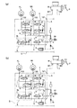
以下、本発明を実施するための最良の形態を、添付した図面を参照しつつ詳細に説明する。参照する図面において、図1は本発明の一実施の形態のプリント配線基板が適用される車両用ブレーキ液圧制御装置のブレーキ液圧回路図であり、図2はアンチロックブレーキ制御時における車両用ブレーキ液圧制御装置の状態を示すブレーキ液圧回路図であって、(a)は車輪ブレーキに作用するブレーキ液圧を減圧する場合を示す図、(b)は車輪ブレーキに作用するブレーキ液圧を一定に保持する場合を示す図である。また、図3は非ペダル操作時のブレーキ制御時における車両用ブレーキ液圧制御装置の状態を示すブレーキ液圧回路図である。ここで、非ペダル操作時とは、ブレーキペダルを操作していない状態を言う。 Hereinafter, the best mode for carrying out the present invention will be described in detail with reference to the accompanying drawings. In the drawings to be referred to, FIG. 1 is a brake hydraulic circuit diagram of a vehicle brake hydraulic pressure control device to which a printed wiring board according to an embodiment of the present invention is applied, and FIG. 2 is a vehicle hydraulic control circuit during antilock brake control. It is a brake fluid pressure circuit diagram showing the state of a brake fluid pressure control device, (a) is a diagram showing a case where the brake fluid pressure acting on the wheel brake is reduced, and (b) is the brake fluid pressure acting on the wheel brake. It is a figure which shows the case where is kept constant. FIG. 3 is a brake fluid pressure circuit diagram showing the state of the vehicle brake fluid pressure control device during brake control during non-pedal operation. Here, the time of non-pedal operation means a state where the brake pedal is not operated.
図1に示すように、車両用ブレーキ液圧制御装置Sは、運転者がブレーキペダルPに加える踏力に応じたブレーキ液圧を発生するマスタシリンダMと、車輪ブレーキFL,RR,RL,FRとの間に配置されている。マスタシリンダMの二つの出力ポートM1,M2は、後記するポンプボディ100の入口ポート121に接続され、ポンプボディ100の出口ポート122が、各車輪ブレーキFL,RR,RL,FRに接続されている。そして、通常時は車両用ブレーキ液圧制御装置S内の入口ポート121から出口ポート122までが連通した油路となっていることで、ブレーキペダルPの踏力が各車輪ブレーキFL,RR,RL,FRに伝達されるようになっている。
As shown in FIG. 1, the vehicle brake fluid pressure control device S includes a master cylinder M that generates brake fluid pressure corresponding to the pedaling force applied by the driver to the brake pedal P, wheel brakes FL, RR, RL, and FR. It is arranged between. Two output ports M1, M2 of the master cylinder M are connected to an
ここで、出力ポートM1から始まる油路は、前輪左側の車輪ブレーキFLと後輪右側の車輪ブレーキRRに通じており、出力ポートM2から始まる油路は、前輪右側の車輪ブレーキFRと後輪左側の車輪ブレーキRLに通じている。なお、以下では、出力ポートM1から始まる油路を「第一系統」と称し、出力ポートM2から始まる油路を「第二系統」と称する。 Here, the oil path starting from the output port M1 leads to the wheel brake FL on the left side of the front wheel and the wheel brake RR on the right side of the rear wheel, and the oil path starting from the output port M2 is set to the wheel brake FR on the right side of the front wheel and the left side of the rear wheel. To the wheel brake RL. Hereinafter, the oil passage starting from the output port M1 is referred to as “first system”, and the oil passage starting from the output port M2 is referred to as “second system”.
車両用ブレーキ液圧制御装置Sには、その第一系統に各車輪ブレーキFL,RRに対応して二つの制御弁手段Vが設けられており、同様に、その第二系統に各車輪ブレーキRL,FRに対応して二つの制御弁手段Vが設けられている。また、この車両用ブレーキ液圧制御装置Sには、第一系統および第二系統のそれぞれに、リザーバ3、ポンプ4、ダンパ5、オリフィス5a、レギュレータR、吸入弁7、貯留室7aが設けられており、さらに、第一系統のポンプ4と第二系統のポンプ4とを駆動するための共通の電動モータ20を備えている。また、本実施形態では、第二系統にのみ圧力センサ8が設けられている。
The vehicle brake hydraulic pressure control device S is provided with two control valve means V corresponding to each wheel brake FL, RR in the first system, and similarly, each wheel brake RL in the second system. , FR, two control valve means V are provided. The vehicle brake fluid pressure control device S is provided with a
なお、以下では、マスタシリンダMの出力ポートM1,M2から各レギュレータRに至る油路を「出力液圧路A」と称し、第一系統のレギュレータRから車輪ブレーキFL,RRに至る油路および第二系統のレギュレータRから車輪ブレーキRL,FRに至る油路をそれぞれ「車輪液圧路B」と称する。また、出力液圧路Aからポンプ4に至る油路を「吸入液圧路C」と称し、ポンプ4から車輪液圧路Bに至る油路を「吐出液圧路D」と称し、さらに、車輪液圧路Bから吸入液圧路Cに至る油路を「解放路E」と称する。 In the following, the oil passage from the output ports M1, M2 of the master cylinder M to each regulator R is referred to as “output hydraulic pressure passage A”, and the oil passage from the first system regulator R to the wheel brakes FL, RR and The oil passages from the second system regulator R to the wheel brakes RL and FR are respectively referred to as “wheel hydraulic pressure passage B”. In addition, an oil path from the output hydraulic pressure path A to the pump 4 is referred to as “suction hydraulic pressure path C”, an oil path from the pump 4 to the wheel hydraulic pressure path B is referred to as “discharge hydraulic pressure path D”, and The oil path from the wheel hydraulic pressure path B to the suction hydraulic pressure path C is referred to as “release path E”.
制御弁手段Vは、車輪液圧路Bを開放しつつ解放路Eを遮断する状態、車輪液圧路Bを遮断しつつ解放路Eを開放する状態および車輪液圧路Bを遮断しつつ解放路Eを遮断する状態を切り換える機能を有しており、入口弁1、出口弁2、チェック弁1aを備えて構成されている。
The control valve means V opens the wheel hydraulic pressure path B while blocking the release path E, blocks the wheel hydraulic pressure path B while opening the release path E, and blocks the wheel hydraulic pressure path B and releases it. It has a function of switching the state of shutting off the path E, and includes an inlet valve 1, an
入口弁1は、車輪液圧路Bに設けられた常開型の電磁弁である。入口弁1は、通常時に開いていることで、マスタシリンダMから各車輪ブレーキFL,RR,RL,FRへブレーキ液圧が伝達するのを許容している。また、入口弁1は、車輪がロックしそうになったときに図示せぬ制御装置により閉塞されることで、ブレーキペダルPから各車輪ブレーキFL,RR,RL,FRに伝達するブレーキ液圧を遮断する。 The inlet valve 1 is a normally open electromagnetic valve provided in the wheel hydraulic pressure path B. The inlet valve 1 is normally open to allow the brake hydraulic pressure to be transmitted from the master cylinder M to the wheel brakes FL, RR, RL, FR. Further, the inlet valve 1 is blocked by a control device (not shown) when the wheel is about to be locked, so that the brake fluid pressure transmitted from the brake pedal P to each wheel brake FL, RR, RL, FR is cut off. To do.
出口弁2は、車輪液圧路Bと解放路Eとの間に介設された常閉型の弁である。出口弁2は、通常時に閉塞されているが、車輪がロックしそうになったときに図示せぬ制御装置により開放されることで、各車輪ブレーキFL,RR,RL,FRに作用するブレーキ液圧を各リザーバ3に逃がす。
The
チェック弁1aは、各入口弁1に並列に接続されている。このチェック弁1aは、各車輪ブレーキFL,RR,RL,FR側からマスタシリンダM側へのブレーキ液の流入のみを許容する弁であり、ブレーキペダルPからの入力が解除された場合に、入口弁1を閉じた状態にしたときにおいても、各車輪ブレーキFL,RR,RL,FR側からマスタシリンダM側へのブレーキ液の流入を許容する。
The
リザーバ3は、解放路Eに設けられており、各出口弁2が開放されることによって逃がされるブレーキ液圧を吸収する機能を有している。また、リザーバ3とポンプ4との間には、リザーバ3側からポンプ4側へのブレーキ液の流入のみを許容するチェック弁3aが介設されている。
The
ポンプ4は、出力液圧路Aに通じる吸入液圧路Cと車輪液圧路Bに通じる吐出液圧路Dとの間に介設されており、リザーバ3で貯留されているブレーキ液を吸入して吐出液圧路Dに吐出する機能を有している。これにより、リザーバ3によるブレーキ液圧の吸収によって減圧された出力液圧路Aや車輪液圧路Bの圧力状態が回復される。さらに、このポンプ4は、後記するカット弁6が出力液圧路Aから車輪液圧路Bへのブレーキ液の流入を遮断し、且つ、後記する吸入弁7が吸入液圧路Cを開放しているときに、マスタシリンダM、出力液圧路A、吸入液圧路Cおよび貯留室7aに貯留されているブレーキ液を吸入して吐出液圧路Dに吐出する機能を有している。これにより、非ペダル操作時において各車輪ブレーキFL,RR,RL,FRにブレーキ液圧を作用させることが可能となる。
The pump 4 is interposed between the suction hydraulic pressure path C leading to the output hydraulic pressure path A and the discharge hydraulic pressure path D leading to the wheel hydraulic pressure path B, and sucks the brake fluid stored in the
なお、ダンパ5およびオリフィス5aは、その協働作用によってポンプ4から吐出されたブレーキ液の圧力の脈動および後記するレギュレータRが作動することにより発生する脈動を減衰させている。 The damper 5 and the orifice 5a attenuate the pulsation of the pressure of the brake fluid discharged from the pump 4 and the pulsation generated by the operation of the regulator R described later by the cooperative action.
レギュレータRは、出力液圧路Aから車輪液圧路Bへのブレーキ液の流入を許容する状態および遮断する状態を切り換える機能と、出力液圧路Aから車輪液圧路Bへのブレーキ液の流入が遮断されているときに車輪液圧路Bおよび吐出液圧路Dのブレーキ液圧を設定値以下に調節する機能とを有しており、カット弁6、チェック弁6aおよびリリーフ弁6bを備えて構成されている。
The regulator R has a function of switching between a state where the brake fluid is allowed to flow from the output hydraulic pressure passage A to the wheel hydraulic pressure passage B and a state where the brake fluid is blocked, and a brake fluid flow from the output hydraulic pressure passage A to the wheel hydraulic pressure passage B. It has a function of adjusting the brake fluid pressure in the wheel fluid pressure passage B and the discharge fluid pressure passage D to a set value or less when the inflow is cut off, and the cut valve 6, the
カット弁6は、マスタシリンダMに通じる出力液圧路Aと各車輪ブレーキFL,RR,RL,FRに通じる車輪液圧路Bとの間に介設された常開型の電磁弁であり、出力液圧路Aから車輪液圧路Bへのブレーキ液の流入を許容する状態および遮断する状態を切り換えるものである。カット弁6は、通常時に開いていることで、マスタシリンダMから各車輪ブレーキFL,RR,RL,FRへブレーキ液圧が伝達するのを許容している。また、カット弁6は、非ペダル操作時であってポンプ4を作動させるとき、言い換えれば、非ペダル操作時において各車輪ブレーキFL,RR,RL,FRにブレーキ液圧を作用させるときに図示せぬ制御装置により閉塞される。 The cut valve 6 is a normally-open electromagnetic valve interposed between the output hydraulic pressure path A leading to the master cylinder M and the wheel hydraulic pressure path B leading to each wheel brake FL, RR, RL, FR. The state in which the inflow of the brake fluid from the output hydraulic pressure path A to the wheel hydraulic pressure path B is permitted and the state in which the brake fluid is blocked are switched. The cut valve 6 is normally open, thereby allowing the brake hydraulic pressure to be transmitted from the master cylinder M to the wheel brakes FL, RR, RL, FR. The cut valve 6 is not illustrated when the pump 4 is operated when the pedal is not operated, in other words, when the brake fluid pressure is applied to the wheel brakes FL, RR, RL, and FR when the pedal is not operated. It is blocked by the control device.
チェック弁6aは、各カット弁6に並列に接続されている。このチェック弁6aは、出力液圧路Aから車輪液圧路Bへのブレーキ液の流入のみを許容する弁であり、各カット弁6を閉じた状態にしたときにおいて、ブレーキペダルPからの入力があっても、出力液圧路Aから車輪液圧路Bへのブレーキ液の流入を許容する。
The
リリーフ弁6bは、各カット弁6に並列に接続されており、車輪液圧路Bおよび吐出液圧路Dのブレーキ液圧が設定値以上になるのに応じて開弁する。
The
吸入弁7は、吸入液圧路Cに設けられた常閉型の電磁弁であり、吸入液圧路Cを開放する状態および遮断する状態を切り換えるものである。吸入弁7は、非ペダル操作時であってカット弁6が出力液圧路Aから車輪液圧路Bへのブレーキ液の流入を遮断する状態にあるとき、言い換えれば、非ペダル操作時において各車輪ブレーキFL,RR,RL,FRにブレーキ液圧を作用させるときに図示せぬ制御装置により開放(開弁)される。
The
貯留室7aは、吸入液圧路Cであってポンプ4と吸入弁7との間に設けられている。この貯留室7aは、ブレーキ液を貯留するものであり、これにより、吸入液圧路Cに貯留されるブレーキ液の容量が実質的に増大する。
The
圧力センサ8は、出力液圧路Aのブレーキ液圧を計測するものであり、その計測結果は図示せぬ制御装置に随時取り込まれ、かかる制御装置によりマスタシリンダMからブレーキ液圧が出力されているか否か、すなわち、ブレーキペダルPが踏まれているか否かが判定され、さらに、圧力センサ8で計測されたブレーキ液圧の大きさに基づいて、車両の横滑り制御、トラクション制御などが行われる。
The
次に、車両用ブレーキ液圧制御装置Sの動作を、図1乃至図3を参照して詳細に説明する。なお、図2および図3では、簡単のため、第一系統のみを図示しているが、第二系統の場合も同様である。 Next, the operation of the vehicle brake hydraulic pressure control device S will be described in detail with reference to FIGS. 2 and 3, only the first system is shown for simplicity, but the same applies to the second system.
(通常時)
各車輪がロックする可能性のない通常のブレーキ時(通常時)においては、図1に示すように、レギュレータRは出力液圧路Aから車輪液圧路Bへのブレーキ液の流入を許容する状態にあり、吸入弁7は吸入液圧路Cを遮断する状態にあり、制御弁手段Vは車輪液圧路Bを開放しつつ解放路Eを遮断する状態にある。つまり、レギュレータRのカット弁6と制御弁手段Vの入口弁1とが開放(開弁)状態にあり、吸入弁7と制御弁手段Vの出口弁2とが閉塞(閉弁)状態にある。したがって、ブレーキペダルPの踏力に起因して発生したブレーキ液圧は、そのまま車輪ブレーキFL,RR,RL,FRに作用する。なお、入口弁1およびカット弁6が常開型の電磁弁であり、出口弁2および吸入弁7が常閉型の電磁弁であるから、通常時においては、総ての電磁弁が消磁された状態にある。
(Normal time)
At the time of normal braking (normal time) where each wheel is not likely to lock, the regulator R allows the brake fluid to flow from the output hydraulic pressure path A to the wheel hydraulic pressure path B as shown in FIG. In this state, the
(アンチロックブレーキ制御)
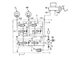
ブレーキペダルPを踏み込んでいる最中に、車輪がロック状態に入りそうになると、図示せぬ制御装置によりアンチロックブレーキ制御が開始される。ここで、アンチロックブレーキ制御とは、ロック状態に入りそうな車輪の車輪ブレーキに対応する制御弁手段Vを制御して、車輪ブレーキに作用するブレーキ液圧を減圧、増圧あるいは一定に保持することをいう。なお、アンチロックブレーキ制御時においても、図2(a)に示すように、レギュレータRは出力液圧路Aから車輪液圧路Bへのブレーキ液の流入を許容する状態にあり、吸入弁7は吸入液圧路Cを遮断する状態にある。
(Anti-lock brake control)
If the wheel is about to enter a locked state while the brake pedal P is being depressed, anti-lock brake control is started by a control device (not shown). Here, the anti-lock brake control means that the control valve means V corresponding to the wheel brake of the wheel which is likely to enter the locked state is controlled, and the brake fluid pressure acting on the wheel brake is reduced, increased or kept constant. That means. Even during the anti-lock brake control, as shown in FIG. 2A, the regulator R is in a state of allowing the brake fluid to flow from the output hydraulic pressure passage A to the wheel hydraulic pressure passage B, and the
以下では、左前側の車輪(車輪ブレーキFLにより制動される車輪)がロック状態に入りそうになっていると想定してアンチロックブレーキ制御時における制御弁手段Vの動作を説明する。 In the following, the operation of the control valve means V during antilock brake control will be described on the assumption that the left front wheel (wheel braked by the wheel brake FL) is about to enter the locked state.
車輪ブレーキFLに作用するブレーキ液圧を減圧する場合には、図2(a)に示すように、車輪ブレーキFLに対応する制御弁手段Vにより車輪液圧路Bが遮断され、解放路Eが開放される。つまり、図示せぬ制御装置により入口弁1を励磁して閉塞(閉弁)状態にするとともに、出口弁2を励磁して開放(開弁)状態にする。このようにすると、車輪ブレーキFLに通じる車輪液圧路Bのブレーキ液が解放路Eを通ってリザーバ3に流入し、その結果、車輪ブレーキFLに作用していたブレーキ液圧が減圧される。
When the brake hydraulic pressure acting on the wheel brake FL is reduced, as shown in FIG. 2A, the wheel hydraulic pressure path B is shut off by the control valve means V corresponding to the wheel brake FL, and the release path E is Opened. That is, the inlet valve 1 is excited and closed (closed) by a control device (not shown), and the
車輪ブレーキFLに作用するブレーキ液圧を一定に保持する場合は、図2(b)に示すように、車輪ブレーキFLに対応する制御弁手段Vにより車輪液圧路Bおよび解放路Eがそれぞれ遮断される。つまり、図示せぬ制御装置により入口弁1を励磁して閉塞(閉弁)状態にするとともに、出口弁2を消磁して閉塞(閉弁)状態にする。このようにすると、車輪ブレーキFL、入口弁1、出口弁2で閉じられた油路内にブレーキ液が閉じ込められることになり、その結果、車輪ブレーキFLに作用していたブレーキ液圧が一定に保持される。
When the brake fluid pressure acting on the wheel brake FL is kept constant, as shown in FIG. 2 (b), the wheel fluid pressure path B and the release path E are cut off by the control valve means V corresponding to the wheel brake FL, respectively. Is done. That is, the inlet valve 1 is excited and closed (closed) by a control device (not shown), and the
車輪ブレーキFLに作用するブレーキ液圧を増圧する場合は、車輪ブレーキFLに対応する制御弁手段Vにより車輪液圧路Bが解放され、解放路Eが遮断される。つまり、図示せぬ制御装置により入口弁1を消磁して開放(開弁)状態にするとともに、出口弁2を消磁して閉塞(閉弁)状態にする(図1参照)。このようにすると、ブレーキペダルPの踏力に起因して発生したブレーキ液圧が車輪ブレーキFLに直接作用することになり、その結果、車輪ブレーキFLに作用するブレーキ液圧が増圧される。
When the brake hydraulic pressure acting on the wheel brake FL is increased, the wheel hydraulic pressure path B is released and the release path E is blocked by the control valve means V corresponding to the wheel brake FL. That is, the inlet valve 1 is demagnetized and opened (opened) by a control device (not shown), and the
なお、アンチロックブレーキ制御中は、電動モータ20が駆動し、これに伴ってポンプ4が作動する。これにより、リザーバ3に貯留されたブレーキ液が吐出液圧路Dを介して車輪液圧路Bに還流される。また、ポンプ4が作動することにより吐出液圧路D等に発生する脈動は、ダンパ5およびオリフィス5aの協働作用によって吸収・抑制されるので、ポンプ4を作動させてもブレーキペダルPの操作フィーリングが阻害されることもない。
During the antilock brake control, the
(非ペダル操作時におけるブレーキ制御)
非ペダル操作時においては、車両の状態に応じて、図示せぬ制御装置により、横滑り制御やトラクション制御が開始される。なお、ここでは、非ペダル操作時に左前側の車輪(車輪ブレーキFLにより制動される車輪)を制動させる場合を想定して車両用ブレーキ液圧制御装置Sの動作を説明する。
(Brake control during non-pedal operation)
During non-pedal operation, skid control and traction control are started by a control device (not shown) according to the state of the vehicle. Here, the operation of the vehicle brake hydraulic pressure control device S will be described on the assumption that the left front wheel (the wheel braked by the wheel brake FL) is braked during non-pedal operation.
非ペダル操作時において左前側の車輪を制動する場合は、図3に示すように、レギュレータRにより出力液圧路Aから車輪液圧路Bへのブレーキ液の流入が遮断されるとともに、吸入弁7により吸入液圧路Cが解放され、さらに、車輪ブレーキFLに対応する制御弁手段Vにより車輪ブレーキFLに通じる車輪液圧路Bが開放され、かかる状態においてポンプ4によりマスタシリンダM、出力液圧路A、吸入液圧路Cおよび貯留室7aに貯留されているブレーキ液が吐出液圧路Dに吐出される。つまり、図示せぬ制御装置によりカット弁6が励磁されて閉塞(閉弁)状態にされ、吸入弁7が励磁されて開放(開弁)状態にされ、さらに、制動したい車輪に対応する制御弁手段V以外の制御弁手段Vにおいて入口弁が励磁されて閉塞(閉弁)状態にされ、かかる状態において、ポンプ4を作動させるべく電動モータ20が駆動させられる。そして、ポンプ4により吐出液圧路Dに供給されたブレーキ液は、カット弁6が閉塞状態にされているが故に、車輪ブレーキFLに通じる車輪液圧路Bのみに流入し、その結果、車輪ブレーキFLにブレーキ液圧が作用し、左前側の車輪が制動されることになる。
When braking the left front wheel during non-pedal operation, as shown in FIG. 3, the inflow of brake fluid from the output hydraulic pressure path A to the wheel hydraulic pressure path B is blocked by the regulator R, and the
このとき、貯留室7aにより吸入液圧路Cの容量が実質的に増大しているので、ポンプ4の始動時であっても安定的にブレーキ液を車輪液圧路Bに供給することが可能となる。
At this time, since the capacity of the suction fluid pressure passage C is substantially increased by the
なお、非ペダル操作時におけるブレーキ制御により、車輪液圧路Bおよび吐出液圧路Dのブレーキ液圧が設定値以上になった場合には、リリーフ弁6bの働きにより車輪液圧路Bおよび吐出液圧路D内のブレーキ液が出力液圧路Aに逃がされ、その結果、車輪ブレーキFLに過剰なブレーキ液圧が作用することが回避される。
When the brake fluid pressure in the wheel fluid pressure passage B and the discharge fluid pressure passage D exceeds a set value due to brake control during non-pedal operation, the
また、レギュレータRが作動することによって吐出液圧路D等に発生する脈動は、ダンパ5およびオリフィス5aの協働作用によって吸収・抑制されるので、当該脈動に起因する作動音も小さくなる。 Further, since the pulsation generated in the discharge hydraulic pressure path D and the like by the operation of the regulator R is absorbed and suppressed by the cooperative action of the damper 5 and the orifice 5a, the operation sound caused by the pulsation is also reduced.
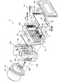
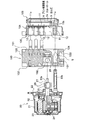
次に、車両用ブレーキ液圧制御装置Sの具体的な構造を、図4および図5を参照して詳細に説明する。
参照する図面において、図4は本発明に係る車両用ブレーキ液圧制御装置の分解斜視図であり、図5は本発明に係る車両用ブレーキ液圧制御装置の分解断面図である。
Next, a specific structure of the vehicle brake hydraulic pressure control device S will be described in detail with reference to FIGS. 4 and 5.
In the drawings to be referred to, FIG. 4 is an exploded perspective view of the vehicle brake hydraulic pressure control device according to the present invention, and FIG. 5 is an exploded cross-sectional view of the vehicle brake hydraulic pressure control device according to the present invention.
図4に示すように、車両用ブレーキ液圧制御装置Sは、各種部材・機器の基体となるポンプボディ(基体)100と、ポンプボディ100の第一取付面101に一体に固着され、電子制御ユニット14(制御装置)などが収容されるコントロールハウジング10と、ポンプボディ100の第二取付面102に一体に固着され、ブレーキ液を送るポンプ4(図1参照)の動力となる電動モータ20とを主に備えている。
As shown in FIG. 4, the vehicle brake hydraulic pressure control device S is integrally fixed to a pump body (base body) 100 serving as a base body of various members and devices and a first mounting
コントロールハウジング10は、電子制御ユニット14(以下、プリント配線基板14と称す)などとの端子部材(端子部材群15A,15B)が埋設された支持板部11を備えるコントロールケース10Aと、このコントロールケース10Aのプリント配線基板14側の開口部を密閉するコントロールカバー10Bとを備えており、ポンプボディ100の第一取付面101にシール部材10Cを介して取り付けられることによって、その内部にプリント配線基板14などを収容するための密閉された部屋(容積の大きな部屋)R1が形成される。なお、図5に示すように、支持板部11のポンプボディ100側の面には、電磁弁を駆動させるための電磁コイル12が取り付けられている。
The
電動モータ20は、モータケース21、モータカバー22およびロータ23を主に備えている。モータケース21は、略有底円筒状に形成された部材であり、その開口部にモータカバー22が覆設されることによって、その内部にロータ23を収容するための部屋(容積の大きな部屋)R2が形成される。また、ロータ23の出力軸23aは、モータケース21の底部に固定されるボールベアリング24と、モータカバー22に固定されるボールベアリング25と、ポンプボディ100のモータ穴132に固定されるボールベアリング26とにより回転自在に支持されている。そして、この出力軸23aの適所(ボールベアリング25,26の間に位置する部分)には、偏心軸部27が設けられ、偏心軸部27には、ポンプ4のプランジャを往復動させるために、その外周面でプランジャを適宜押圧するボールベアリング28が設けられている。
The
なお、前記したモータケース21とモータカバー22とで形成される部屋R2は、モータケース21とモータカバー22の接触部分の微細な隙間や出力軸23aを支持するボールベアリング25の隙間を介して外部と連通しているが、モータケース21とモータカバー22との間およびモータカバー22とポンプボディ100の第二取付面102との間に図示せぬシール部材が介設されるので、外部とは遮断された(密閉された)状態となっている。
The chamber R2 formed by the
また、ロータ23に電力を供給するためのモータ接続端子23bは、ポンプボディ100の下部に形成された貫通孔131に挿入され、その先端部分がコントロールハウジング10のバスバー13を介してプリント配線基板14に接続される。すなわち、この貫通孔131によって、コントロールハウジング10内の部屋R1と、モータケース21内の部屋R2とが連通する。また、この貫通孔131の適所には、貫通孔131と外部とに連通する段状の通気孔133が形成され、この通気孔133には、通気防水部材Gが設けられている。ここで、通気防水部材Gは、外部からの水の浸入を阻止し、かつ空気の出入りのみを許容する部材であり、例えば周知であるゴアテックス(登録商標)などを通気防水部材Gとして採用することができる。
A
ポンプボディ100は、略直方体に形成される金属部品であり、その各面には電磁弁などの各種機器を設置するための穴(孔)が適宜形成されており、その内部にはブレーキ液の通り道となる油路が適宜形成されている。なお、本実施形態では、ポンプボディ100の左半分で前記した第一系統が構築され、右半分で第二系統が構築される。
The
図6は本発明のプリント配線基板14の正面図、図7はコントロールケース10Aにプリント配線基板14が収納された状態を示す正面図である。
プリント配線基板14は、図示しない電子部品が搭載され、コントロールケース10A(図7参照)に収納可能な長方形状に形成されており、コントロールケース10Aの支持板部11(図4参照)に一体に立設された4つの支持ボス11aに、各係合孔14cを係合させることにより固定的に支持される(図5参照)。
プリント配線基板14には、コントロールケース10Aに設けられた端子部材群15A,15B(図4参照)に対応したスルーホールTHを有する直線状に配列されたランド群14A,14Bが設けられ、これらの各ランド14a,14bに、前記端子部材群15A,15Bの各端子部材15a,15bが貫通されてはんだ付けされるようになっている。端子部材群15A,15Bの各端子部材15a,15bの基端側は、前記圧力センサ8や電磁コイル12の図示しない端子等に接続されている。また、各端子部材15a,15bの先端部分は、各ランド14a,14bのスルーホールTHに挿入し易い先細り形状としてある。各ランド14a,14bは、プリント配線基板14の両面にスルーホールTHを介して形成される導電部分を有している(図8(a)参照)。
6 is a front view of the printed
The printed
The printed
本実施形態では、図6,図7に示すように、プリント配線基板14のランド群14Aの、はんだ付け方向(図7中矢印Y方向)の下流側(最端)に、前記端子部材15aと接合されず、はんだ付け終了後に残る余分なはんだのみを残留させるための捨てランド16A,16Bが設けられている。この捨てランド16A,16Bは、回路パターンから絶縁された金属製のパターンで形成されている。この捨てランド16A,16Bは、丸形を基本とした形状としてあるが、隣接するランド14a’(図7参照)と所定の間隔を隔ててプリント配線基板14の基板端部14dに配置されている。なお、ランド16A,16Bの形状は、丸形に限られることはなく、三角形状、矩形状、多角形状等、種々採用することができる。隣接するランド14a’との所定の間隔は、はんだ付け時にブリッジ等の生じることのないものであればよく、例えば、ランド14a間の距離と同等の距離とすることで、捨てランド16A,16Bとしての役割を持たせることが可能である。
In the present embodiment, as shown in FIGS. 6 and 7, the
次に、このようなプリント配線基板14における各ランド14a,14bと各端子部材15a,15bとのはんだ付けについて説明する。
本実施形態では、図示しないはんだ付け装置を利用して、引きはんだによる端子部材群15A,15B(図4参照)ごとのはんだ付けを行う。ここで、端子部材群15A(図4参照)においては、図7に示すように,縦方向直線状のランド列L1,L2,L3ごとに図中矢印Y方向へ後記するこて先K(図8,図9各図)を移動してはんだ付けを行う。したがって、捨てランド16A,16Bは、ランド列L1,L3の下流側に位置する。また、端子部材群15B(図4参照)においては、図7に示すように、横方向直線状のランド列L4,L5,L6ごとに図中矢印X方向へ後記するこて先Kを移動してはんだ付けを行う。ここで、列ごとのはんだ付けの順序は、任意に設定可能であり、また、こて先Kの温度、移動速度、供給されるはんだの量は、良好なはんだ付けを行うことのできる所定の値に制御される。
Next, soldering between the
In the present embodiment, soldering is performed for each of the
図8(a),(b)、図9(a),(b)は、はんだ付けが行われる様子を模式的に示した図である。まず、はんだ付けに先立って、プリント配線基板14をコントロールケース10Aに組み込み、スルーホールTHに各端子部材15a,15bを貫通させる(貫通させる工程)。そして、図示しないはんだ付け装置の所定の位置に、プリント配線基板14を取り付けた状態のコントロールケース10A(図7参照)を配置してはんだ付けを行う(はんだ付け工程)。そうすると、図8(a)に示すように、図示しないアームが操作されて、こて先Kが所定のランド列、ここでは、ランド列L1の先頭に近づけられる。そして、はんだHがこて先Kに供給され、図中矢印Y方向へこて先KとはんだHとが同時に移動されて、引きはんだによるはんだ付けが開始される。ここで、こて先Kは、門型に形成されており、端子部材15aを跨ぐ形でスライドしながらはんだ付けを行うことができるようになっており、図8(b)に示すように、ランド列L1の下流側に向けて、順次、各ランド14aに対して端子部材15aがはんだ付けされる。このとき、こて先Kにより溶融したはんだHは、各ランド14aのスルーホールTHを伝わって、プリント配線基板14の下面側(端子部材15aが挿入される側)に流れて凝固する。
8 (a), 8 (b), 9 (a), and 9 (b) are diagrams schematically showing how soldering is performed. First, prior to soldering, the printed
その後、図9(a)に示すように、ランド列L1の最下流のランド14a’(捨てランド16Aに隣接するランド)のはんだ付けが終了した後、捨てランド16Aに少なくともこて先Kが到達する時点で、こて先KからはんだHが離れ、こて先Kに対するはんだHの供給が停止される。これにより、こて先Kが捨てランド16Aに移動した状態(ランド14a’とランド16Aとに跨った状態)では、こて先Kに少量のはんだHが残っているだけとなり、この残ったはんだHは、捨てランド16Aに引っ張られるかたちで吸収されることとなる。なお、捨てランド16Aにこて先Kが到達する以前、例えば、ランド14a’におけるはんだ付けが行われている途中で、はんだHの供給が停止されるように、はんだ付け装置を制御することもできる。
Thereafter, as shown in FIG. 9A, after the soldering of the most
その後、図9(a)に示すように、捨てランド16A上にこて先Kが到達したところで、図示しないアームが上昇移動され、こて先Kがプリント配線基板14から離間される(離間させる工程)。このとき、捨てランド16Aに残留されたはんだHは、その量にもよるが、幾分多めに残留されたときでも、捨てランド16Aに対して全体に広がるようにして吸収されることとなる。なお、捨てランド16Aからこて先Kが上昇移動する際には、コントロールケース10Aの側壁10A’とこて先Kとの間に所定の間隔が形成されるように、予め捨てランド16A上におけるこて先Kの停止位置が制御されるようになっている。以上のようにして、ランド列L1におけるはんだ付けが終了する。そして、その他のランド列L2等におけるはんだ付けが順次行われる。
Thereafter, as shown in FIG. 9A, when the tip K arrives on the
このような本発明の実施形態に係るプリント配線基板14によれば、ランド列L1,L3におけるはんだ付け方向の下流側に、捨てランド16A,16Bが設けられているので、引きはんだ終了後に、この捨てランド16A,16Bに対して、こて先Kに付着するはんだHを残留させることができる(図9(a),(b)参照)。これにより、捨てランド16A,16Bの直前のランド14a’に対して通常の引きはんだを行うことができるようになり、従来のようなはんだHの糸引きやツノ等が生じるのを未然に防止することができる。また、捨てランド16A,16Bは、はんだ付け方向(図7中矢印Y方向)の下流側に設けられているので、こて先K(図8(a),(b)、図9(a),(b)参照)の移動方向に僅かに延長移動させることで糸引きやツノ等の発生を抑えることができる。これにより、はんだの残留に係るこて先Kの特別な移動、例えば、従来のようなはんだ切りを行うためのスライド等の長い移動が必要とならない。したがって、はんだをスムーズに切ることができる。また、従来のようなはんだ切りを行うためのスペースが必要なくなるので、プリント配線基板14の小型化を図ることができる。なお、捨てランド16A,16Bには、端子部材15a(15b)が存在しないので、捨てランド16A,16Bからこて先Kを離間する際に、はんだHの糸引きやツノ等が生じることもない。
According to such a printed
さらに、プリント配線基板14は、捨てランド16A,16Bが基板端部16dに位置するように設けられているので、基板端部16dにおいて従来のような余分なスペースを設ける必要がなくなり、小型化を実現することができる。
Further, since the printed
また、捨てランド16A,16Bに少なくともこて先Kが到達する時点で、こて先Kに対するはんだHの供給が停止されるようになっているので、引きはんだ終了後にこて先Kに残るはんだHが減少され、捨てランド16A,16Bで残留されるはんだHの量も少なくなる。これにより、最下流ランド14a’や捨てランド16A,16BにはんだHの糸引きやツノ等が生じるのをより一層防止することができる。
In addition, since the supply of the solder H to the tip K is stopped at least when the tip K reaches the discarded
以上、本発明の実施形態について説明したが、本発明は、前記した実施形態に限定されるものではなく、適宜変更して実施することができる。
捨てランド16A,16Bは、基板端部16dに設けられるものに限られず、ランド14aの下流側に設けられるものであれば、プリント配線基板14の中央付近やその他の場所等に設けても良い。また、単一のランド14a(15a)の下流側に設けても良い。
As mentioned above, although embodiment of this invention was described, this invention is not limited to above-described embodiment, It can implement by changing suitably.
The discarded lands 16A and 16B are not limited to those provided on the board end 16d, and may be provided near the center of the printed
10A コントロールケース
10B コントロールカバー
11 支持板部
11a 支持ボス
14 電子制御ユニット(プリント配線基板)
14A,14B ランド群
14a,14b ランド
14d 基板端部
15A,15B 端子部材群
15a,15b 端子部材
16A,16B 捨てランド
16d 基板端部
S 車両用ブレーキ液圧制御装置
14A,
Claims (5)
前記ランドに前記端子部材を貫通して引きはんだによるはんだ付けにより、前記端子部材と前記ランドとが接合されるプリント配線基板において、
前記端子部材が突出する側から引きはんだを行う際の、前記ランドのはんだ付け方向の下流側に、前記ランドと間隔を隔てて、前記端子部材と接合されず、はんだのみを残留させる捨てランドを設けたことを特徴とするプリント配線基板。 A land provided with a through hole through which a terminal member of a component to be mounted is penetrated,
In the printed wiring board in which the terminal member and the land are joined by soldering by pulling solder through the terminal member to the land,
When performing pull soldering from the side from which the terminal member protrudes, a waste land that is not joined to the terminal member and spaced apart from the land is spaced downstream from the land in the soldering direction. A printed wiring board characterized by being provided.
前記スルーホールに前記端子部材を貫通させる工程と、
こて先にはんだを供給しつつ、前記こて先を前記ランドに沿って移動させることで前記ランドと前記端子部材とをはんだ付けする工程と、
前記こて先を前記捨てランド上まで移動した時点で、前記こて先を前記プリント配線基板から離間させる工程とを有することを特徴とするプリント配線基板のはんだ付け方法。 A method for soldering a printed wiring board according to any one of claims 1 to 3,
Passing the terminal member through the through hole;
Soldering the land and the terminal member by moving the tip along the land while supplying solder to the tip; and
And a step of separating the tip from the printed wiring board when the tip is moved onto the discarded land.
Priority Applications (1)
| Application Number | Priority Date | Filing Date | Title |
|---|---|---|---|
| JP2004106531A JP2005294480A (en) | 2004-03-31 | 2004-03-31 | Printed circuit board and method for soldering printed circuit board |
Applications Claiming Priority (1)
| Application Number | Priority Date | Filing Date | Title |
|---|---|---|---|
| JP2004106531A JP2005294480A (en) | 2004-03-31 | 2004-03-31 | Printed circuit board and method for soldering printed circuit board |
Publications (1)
| Publication Number | Publication Date |
|---|---|
| JP2005294480A true JP2005294480A (en) | 2005-10-20 |
Family
ID=35327082
Family Applications (1)
| Application Number | Title | Priority Date | Filing Date |
|---|---|---|---|
| JP2004106531A Pending JP2005294480A (en) | 2004-03-31 | 2004-03-31 | Printed circuit board and method for soldering printed circuit board |
Country Status (1)
| Country | Link |
|---|---|
| JP (1) | JP2005294480A (en) |
Cited By (1)
| Publication number | Priority date | Publication date | Assignee | Title |
|---|---|---|---|---|
| EP2886408A1 (en) | 2013-11-18 | 2015-06-24 | Nissin Kogyo Co., Ltd. | Electronic control unit and vehicle brake hydraulic pressure control unit |
-
2004
- 2004-03-31 JP JP2004106531A patent/JP2005294480A/en active Pending
Cited By (2)
| Publication number | Priority date | Publication date | Assignee | Title |
|---|---|---|---|---|
| EP2886408A1 (en) | 2013-11-18 | 2015-06-24 | Nissin Kogyo Co., Ltd. | Electronic control unit and vehicle brake hydraulic pressure control unit |
| US9592799B2 (en) | 2013-11-18 | 2017-03-14 | Autoliv Nissin Brake Systems Japan Co., Ltd. | Electronic control unit and vehicle brake hydraulic pressure control unit |
Similar Documents
| Publication | Publication Date | Title |
|---|---|---|
| EP1707463B1 (en) | Vehicle brake hydraulic pressure control unit | |
| US7578564B2 (en) | Brake hydraulic pressure control unit for vehicle | |
| US11479228B2 (en) | Brake hydraulic pressure controller and motorcycle brake system | |
| US8746811B2 (en) | Brake fluid pressure control device | |
| JP3777262B2 (en) | Plastic parts | |
| JP2002520211A (en) | Brake pressure control device | |
| KR101011352B1 (en) | Hydraulic braking system | |
| JP2005294481A (en) | Printed circuit board connection structure | |
| JP2001065514A (en) | Proportional pressure control valve | |
| JP2005294480A (en) | Printed circuit board and method for soldering printed circuit board | |
| EP1396403B1 (en) | Braking apparatus for vehicle | |
| JP4368828B2 (en) | Brake control device for bar handle vehicle | |
| CN111231916B (en) | Brake hydraulic control device | |
| CN111845672B (en) | Brake hydraulic control device | |
| JP4319999B2 (en) | Brake control device for bar handle vehicle | |
| JP2004175166A (en) | Brake fluid pressure control device | |
| JP3660146B2 (en) | Brake hydraulic pressure control device for vehicles | |
| JP3975155B2 (en) | Resin case | |
| US10967842B2 (en) | Brake hydraulic pressure controller and motorcycle brake system | |
| CN111231914B (en) | Brake hydraulic control device and method for manufacturing brake hydraulic control device | |
| JP2721528B2 (en) | Sump device in anti-skid brake control device | |
| JP4778529B2 (en) | Brake hydraulic pressure control device for bar handle vehicle | |
| JP2010280269A (en) | Brake hydraulic pressure control device for vehicles | |
| JP2005289159A (en) | Brake hydraulic pressure control device for vehicles | |
| JP5491813B2 (en) | Brake hydraulic pressure control device for vehicles |