JP2005294420A - Electrolytic capacitor or its manufacturing method - Google Patents
Electrolytic capacitor or its manufacturing method Download PDFInfo
- Publication number
- JP2005294420A JP2005294420A JP2004105231A JP2004105231A JP2005294420A JP 2005294420 A JP2005294420 A JP 2005294420A JP 2004105231 A JP2004105231 A JP 2004105231A JP 2004105231 A JP2004105231 A JP 2004105231A JP 2005294420 A JP2005294420 A JP 2005294420A
- Authority
- JP
- Japan
- Prior art keywords
- electrode layer
- electrolytic capacitor
- layer
- main electrode
- polymer
- Prior art date
- Legal status (The legal status is an assumption and is not a legal conclusion. Google has not performed a legal analysis and makes no representation as to the accuracy of the status listed.)
- Pending
Links
- 239000003990 capacitor Substances 0.000 title claims abstract description 218
- 238000004519 manufacturing process Methods 0.000 title claims abstract description 63
- 238000000034 method Methods 0.000 claims abstract description 41
- 239000010410 layer Substances 0.000 claims description 290
- 239000007784 solid electrolyte Substances 0.000 claims description 50
- 229920000642 polymer Polymers 0.000 claims description 48
- 239000002245 particle Substances 0.000 claims description 38
- 229910052751 metal Inorganic materials 0.000 claims description 30
- 239000002184 metal Substances 0.000 claims description 29
- OKTJSMMVPCPJKN-UHFFFAOYSA-N Carbon Chemical compound [C] OKTJSMMVPCPJKN-UHFFFAOYSA-N 0.000 claims description 13
- 229910052799 carbon Inorganic materials 0.000 claims description 13
- 239000002344 surface layer Substances 0.000 claims description 5
- 238000007743 anodising Methods 0.000 claims description 4
- 239000002356 single layer Substances 0.000 claims description 3
- 238000005868 electrolysis reaction Methods 0.000 claims 1
- 238000007796 conventional method Methods 0.000 abstract description 3
- 229920001940 conductive polymer Polymers 0.000 description 37
- 239000007787 solid Substances 0.000 description 34
- 239000000178 monomer Substances 0.000 description 26
- 239000000463 material Substances 0.000 description 24
- -1 polyethylenedioxy Polymers 0.000 description 21
- 239000000243 solution Substances 0.000 description 20
- 230000008569 process Effects 0.000 description 18
- 239000002019 doping agent Substances 0.000 description 16
- 239000007800 oxidant agent Substances 0.000 description 11
- 229920005989 resin Polymers 0.000 description 10
- 239000011347 resin Substances 0.000 description 10
- BQCADISMDOOEFD-UHFFFAOYSA-N Silver Chemical compound [Ag] BQCADISMDOOEFD-UHFFFAOYSA-N 0.000 description 9
- 230000020169 heat generation Effects 0.000 description 9
- 229910052709 silver Inorganic materials 0.000 description 9
- 239000004332 silver Substances 0.000 description 9
- PXHVJJICTQNCMI-UHFFFAOYSA-N Nickel Chemical compound [Ni] PXHVJJICTQNCMI-UHFFFAOYSA-N 0.000 description 8
- 239000010949 copper Substances 0.000 description 8
- 239000011888 foil Substances 0.000 description 8
- 239000007788 liquid Substances 0.000 description 8
- 230000007246 mechanism Effects 0.000 description 8
- 229910052782 aluminium Inorganic materials 0.000 description 7
- XAGFODPZIPBFFR-UHFFFAOYSA-N aluminium Chemical compound [Al] XAGFODPZIPBFFR-UHFFFAOYSA-N 0.000 description 7
- 230000006378 damage Effects 0.000 description 7
- 238000010438 heat treatment Methods 0.000 description 7
- 230000001590 oxidative effect Effects 0.000 description 7
- 229920000573 polyethylene Polymers 0.000 description 7
- GUVRBAGPIYLISA-UHFFFAOYSA-N tantalum atom Chemical compound [Ta] GUVRBAGPIYLISA-UHFFFAOYSA-N 0.000 description 7
- 239000002033 PVDF binder Substances 0.000 description 6
- 239000006229 carbon black Substances 0.000 description 6
- 239000003792 electrolyte Substances 0.000 description 6
- BASFCYQUMIYNBI-UHFFFAOYSA-N platinum Chemical compound [Pt] BASFCYQUMIYNBI-UHFFFAOYSA-N 0.000 description 6
- 229920002981 polyvinylidene fluoride Polymers 0.000 description 6
- 229910052715 tantalum Inorganic materials 0.000 description 6
- MTPVUVINMAGMJL-UHFFFAOYSA-N trimethyl(1,1,2,2,2-pentafluoroethyl)silane Chemical compound C[Si](C)(C)C(F)(F)C(F)(F)F MTPVUVINMAGMJL-UHFFFAOYSA-N 0.000 description 6
- RYGMFSIKBFXOCR-UHFFFAOYSA-N Copper Chemical compound [Cu] RYGMFSIKBFXOCR-UHFFFAOYSA-N 0.000 description 5
- 239000004698 Polyethylene Substances 0.000 description 5
- RTAQQCXQSZGOHL-UHFFFAOYSA-N Titanium Chemical compound [Ti] RTAQQCXQSZGOHL-UHFFFAOYSA-N 0.000 description 5
- 230000009471 action Effects 0.000 description 5
- 239000000919 ceramic Substances 0.000 description 5
- 238000006243 chemical reaction Methods 0.000 description 5
- 230000000052 comparative effect Effects 0.000 description 5
- 229910052802 copper Inorganic materials 0.000 description 5
- 239000002923 metal particle Substances 0.000 description 5
- 230000004048 modification Effects 0.000 description 5
- 238000012986 modification Methods 0.000 description 5
- 150000003839 salts Chemical class 0.000 description 5
- 239000002904 solvent Substances 0.000 description 5
- 239000000126 substance Substances 0.000 description 5
- 239000010936 titanium Substances 0.000 description 5
- LRHPLDYGYMQRHN-UHFFFAOYSA-N N-Butanol Chemical compound CCCCO LRHPLDYGYMQRHN-UHFFFAOYSA-N 0.000 description 4
- NBIIXXVUZAFLBC-UHFFFAOYSA-N Phosphoric acid Chemical compound OP(O)(O)=O NBIIXXVUZAFLBC-UHFFFAOYSA-N 0.000 description 4
- QAOWNCQODCNURD-UHFFFAOYSA-N Sulfuric acid Chemical compound OS(O)(=O)=O QAOWNCQODCNURD-UHFFFAOYSA-N 0.000 description 4
- YTPLMLYBLZKORZ-UHFFFAOYSA-N Thiophene Chemical compound C=1C=CSC=1 YTPLMLYBLZKORZ-UHFFFAOYSA-N 0.000 description 4
- 230000015572 biosynthetic process Effects 0.000 description 4
- 230000007423 decrease Effects 0.000 description 4
- 230000000694 effects Effects 0.000 description 4
- 239000003822 epoxy resin Substances 0.000 description 4
- 239000010931 gold Substances 0.000 description 4
- 238000002844 melting Methods 0.000 description 4
- 230000008018 melting Effects 0.000 description 4
- 239000010955 niobium Substances 0.000 description 4
- 229920000647 polyepoxide Polymers 0.000 description 4
- 229920000123 polythiophene Polymers 0.000 description 4
- 239000011734 sodium Substances 0.000 description 4
- 229910052719 titanium Inorganic materials 0.000 description 4
- XLYOFNOQVPJJNP-UHFFFAOYSA-N water Substances O XLYOFNOQVPJJNP-UHFFFAOYSA-N 0.000 description 4
- LFQSCWFLJHTTHZ-UHFFFAOYSA-N Ethanol Chemical compound CCO LFQSCWFLJHTTHZ-UHFFFAOYSA-N 0.000 description 3
- XEEYBQQBJWHFJM-UHFFFAOYSA-N Iron Chemical compound [Fe] XEEYBQQBJWHFJM-UHFFFAOYSA-N 0.000 description 3
- 239000002253 acid Substances 0.000 description 3
- 239000000853 adhesive Substances 0.000 description 3
- 230000001070 adhesive effect Effects 0.000 description 3
- 239000000460 chlorine Substances 0.000 description 3
- 230000005484 gravity Effects 0.000 description 3
- 229920001903 high density polyethylene Polymers 0.000 description 3
- 239000004700 high-density polyethylene Substances 0.000 description 3
- VLKZOEOYAKHREP-UHFFFAOYSA-N n-Hexane Chemical compound CCCCCC VLKZOEOYAKHREP-UHFFFAOYSA-N 0.000 description 3
- 229910052758 niobium Inorganic materials 0.000 description 3
- GUCVJGMIXFAOAE-UHFFFAOYSA-N niobium atom Chemical compound [Nb] GUCVJGMIXFAOAE-UHFFFAOYSA-N 0.000 description 3
- 238000007747 plating Methods 0.000 description 3
- 239000011148 porous material Substances 0.000 description 3
- GKWLILHTTGWKLQ-UHFFFAOYSA-N 2,3-dihydrothieno[3,4-b][1,4]dioxine Chemical compound O1CCOC2=CSC=C21 GKWLILHTTGWKLQ-UHFFFAOYSA-N 0.000 description 2
- ZCYVEMRRCGMTRW-UHFFFAOYSA-N 7553-56-2 Chemical compound [I] ZCYVEMRRCGMTRW-UHFFFAOYSA-N 0.000 description 2
- CSCPPACGZOOCGX-UHFFFAOYSA-N Acetone Chemical compound CC(C)=O CSCPPACGZOOCGX-UHFFFAOYSA-N 0.000 description 2
- PAYRUJLWNCNPSJ-UHFFFAOYSA-N Aniline Chemical compound NC1=CC=CC=C1 PAYRUJLWNCNPSJ-UHFFFAOYSA-N 0.000 description 2
- WKBOTKDWSSQWDR-UHFFFAOYSA-N Bromine atom Chemical compound [Br] WKBOTKDWSSQWDR-UHFFFAOYSA-N 0.000 description 2
- YLQBMQCUIZJEEH-UHFFFAOYSA-N Furan Chemical compound C=1C=COC=1 YLQBMQCUIZJEEH-UHFFFAOYSA-N 0.000 description 2
- DGAQECJNVWCQMB-PUAWFVPOSA-M Ilexoside XXIX Chemical compound C[C@@H]1CC[C@@]2(CC[C@@]3(C(=CC[C@H]4[C@]3(CC[C@@H]5[C@@]4(CC[C@@H](C5(C)C)OS(=O)(=O)[O-])C)C)[C@@H]2[C@]1(C)O)C)C(=O)O[C@H]6[C@@H]([C@H]([C@@H]([C@H](O6)CO)O)O)O.[Na+] DGAQECJNVWCQMB-PUAWFVPOSA-M 0.000 description 2
- ZOKXTWBITQBERF-UHFFFAOYSA-N Molybdenum Chemical compound [Mo] ZOKXTWBITQBERF-UHFFFAOYSA-N 0.000 description 2
- UFWIBTONFRDIAS-UHFFFAOYSA-N Naphthalene Chemical compound C1=CC=CC2=CC=CC=C21 UFWIBTONFRDIAS-UHFFFAOYSA-N 0.000 description 2
- 229920001609 Poly(3,4-ethylenedioxythiophene) Polymers 0.000 description 2
- KAESVJOAVNADME-UHFFFAOYSA-N Pyrrole Chemical compound C=1C=CNC=1 KAESVJOAVNADME-UHFFFAOYSA-N 0.000 description 2
- NRTOMJZYCJJWKI-UHFFFAOYSA-N Titanium nitride Chemical compound [Ti]#N NRTOMJZYCJJWKI-UHFFFAOYSA-N 0.000 description 2
- 150000007513 acids Chemical class 0.000 description 2
- 150000004996 alkyl benzenes Chemical class 0.000 description 2
- HSFWRNGVRCDJHI-UHFFFAOYSA-N alpha-acetylene Natural products C#C HSFWRNGVRCDJHI-UHFFFAOYSA-N 0.000 description 2
- 229910000147 aluminium phosphate Inorganic materials 0.000 description 2
- MWPLVEDNUUSJAV-UHFFFAOYSA-N anthracene Chemical compound C1=CC=CC2=CC3=CC=CC=C3C=C21 MWPLVEDNUUSJAV-UHFFFAOYSA-N 0.000 description 2
- CUFNKYGDVFVPHO-UHFFFAOYSA-N azulene Chemical compound C1=CC=CC2=CC=CC2=C1 CUFNKYGDVFVPHO-UHFFFAOYSA-N 0.000 description 2
- YXTPWUNVHCYOSP-UHFFFAOYSA-N bis($l^{2}-silanylidene)molybdenum Chemical compound [Si]=[Mo]=[Si] YXTPWUNVHCYOSP-UHFFFAOYSA-N 0.000 description 2
- XTDAIYZKROTZLD-UHFFFAOYSA-N boranylidynetantalum Chemical compound [Ta]#B XTDAIYZKROTZLD-UHFFFAOYSA-N 0.000 description 2
- GDTBXPJZTBHREO-UHFFFAOYSA-N bromine Substances BrBr GDTBXPJZTBHREO-UHFFFAOYSA-N 0.000 description 2
- 229910052794 bromium Inorganic materials 0.000 description 2
- 239000011575 calcium Substances 0.000 description 2
- 230000008859 change Effects 0.000 description 2
- 238000000576 coating method Methods 0.000 description 2
- 239000010941 cobalt Substances 0.000 description 2
- 229910017052 cobalt Inorganic materials 0.000 description 2
- GUTLYIVDDKVIGB-UHFFFAOYSA-N cobalt atom Chemical compound [Co] GUTLYIVDDKVIGB-UHFFFAOYSA-N 0.000 description 2
- 238000001816 cooling Methods 0.000 description 2
- 238000005520 cutting process Methods 0.000 description 2
- 239000012153 distilled water Substances 0.000 description 2
- VYFYYTLLBUKUHU-UHFFFAOYSA-N dopamine Chemical group NCCC1=CC=C(O)C(O)=C1 VYFYYTLLBUKUHU-UHFFFAOYSA-N 0.000 description 2
- 238000001035 drying Methods 0.000 description 2
- 238000005516 engineering process Methods 0.000 description 2
- 125000005678 ethenylene group Chemical group [H]C([*:1])=C([H])[*:2] 0.000 description 2
- 238000001704 evaporation Methods 0.000 description 2
- 230000008020 evaporation Effects 0.000 description 2
- PCHJSUWPFVWCPO-UHFFFAOYSA-N gold Chemical compound [Au] PCHJSUWPFVWCPO-UHFFFAOYSA-N 0.000 description 2
- 229910052737 gold Inorganic materials 0.000 description 2
- 229910052736 halogen Inorganic materials 0.000 description 2
- 150000002367 halogens Chemical class 0.000 description 2
- 239000005457 ice water Substances 0.000 description 2
- 239000011630 iodine Substances 0.000 description 2
- 229910052740 iodine Inorganic materials 0.000 description 2
- 238000004898 kneading Methods 0.000 description 2
- NUJOXMJBOLGQSY-UHFFFAOYSA-N manganese dioxide Chemical compound O=[Mn]=O NUJOXMJBOLGQSY-UHFFFAOYSA-N 0.000 description 2
- 150000002739 metals Chemical class 0.000 description 2
- 229910052750 molybdenum Inorganic materials 0.000 description 2
- 239000011733 molybdenum Substances 0.000 description 2
- 229910052759 nickel Inorganic materials 0.000 description 2
- 238000007254 oxidation reaction Methods 0.000 description 2
- TWNQGVIAIRXVLR-UHFFFAOYSA-N oxo(oxoalumanyloxy)alumane Chemical compound O=[Al]O[Al]=O TWNQGVIAIRXVLR-UHFFFAOYSA-N 0.000 description 2
- VLTRZXGMWDSKGL-UHFFFAOYSA-M perchlorate Inorganic materials [O-]Cl(=O)(=O)=O VLTRZXGMWDSKGL-UHFFFAOYSA-M 0.000 description 2
- 229910052697 platinum Inorganic materials 0.000 description 2
- 229920000767 polyaniline Polymers 0.000 description 2
- 229920000414 polyfuran Polymers 0.000 description 2
- 238000006116 polymerization reaction Methods 0.000 description 2
- 229920000128 polypyrrole Polymers 0.000 description 2
- 238000007639 printing Methods 0.000 description 2
- BBEAQIROQSPTKN-UHFFFAOYSA-N pyrene Chemical compound C1=CC=C2C=CC3=CC=CC4=CC=C1C2=C43 BBEAQIROQSPTKN-UHFFFAOYSA-N 0.000 description 2
- 230000009257 reactivity Effects 0.000 description 2
- 230000000630 rising effect Effects 0.000 description 2
- 229910052708 sodium Inorganic materials 0.000 description 2
- 239000011343 solid material Substances 0.000 description 2
- BDHFUVZGWQCTTF-UHFFFAOYSA-M sulfonate Chemical compound [O-]S(=O)=O BDHFUVZGWQCTTF-UHFFFAOYSA-M 0.000 description 2
- AKEJUJNQAAGONA-UHFFFAOYSA-N sulfur trioxide Chemical compound O=S(=O)=O AKEJUJNQAAGONA-UHFFFAOYSA-N 0.000 description 2
- JBQYATWDVHIOAR-UHFFFAOYSA-N tellanylidenegermanium Chemical compound [Te]=[Ge] JBQYATWDVHIOAR-UHFFFAOYSA-N 0.000 description 2
- 229930192474 thiophene Natural products 0.000 description 2
- WFKWXMTUELFFGS-UHFFFAOYSA-N tungsten Chemical compound [W] WFKWXMTUELFFGS-UHFFFAOYSA-N 0.000 description 2
- 229910052721 tungsten Inorganic materials 0.000 description 2
- 239000010937 tungsten Substances 0.000 description 2
- UONOETXJSWQNOL-UHFFFAOYSA-N tungsten carbide Chemical compound [W+]#[C-] UONOETXJSWQNOL-UHFFFAOYSA-N 0.000 description 2
- 238000005406 washing Methods 0.000 description 2
- ZVWKZXLXHLZXLS-UHFFFAOYSA-N zirconium nitride Chemical compound [Zr]#N ZVWKZXLXHLZXLS-UHFFFAOYSA-N 0.000 description 2
- BQCIDUSAKPWEOX-UHFFFAOYSA-N 1,1-Difluoroethene Chemical compound FC(F)=C BQCIDUSAKPWEOX-UHFFFAOYSA-N 0.000 description 1
- 125000001140 1,4-phenylene group Chemical group [H]C1=C([H])C([*:2])=C([H])C([H])=C1[*:1] 0.000 description 1
- LCPVQAHEFVXVKT-UHFFFAOYSA-N 2-(2,4-difluorophenoxy)pyridin-3-amine Chemical compound NC1=CC=CN=C1OC1=CC=C(F)C=C1F LCPVQAHEFVXVKT-UHFFFAOYSA-N 0.000 description 1
- LYTMVABTDYMBQK-UHFFFAOYSA-N 2-benzothiophene Chemical compound C1=CC=CC2=CSC=C21 LYTMVABTDYMBQK-UHFFFAOYSA-N 0.000 description 1
- FLDCSPABIQBYKP-UHFFFAOYSA-N 5-chloro-1,2-dimethylbenzimidazole Chemical compound ClC1=CC=C2N(C)C(C)=NC2=C1 FLDCSPABIQBYKP-UHFFFAOYSA-N 0.000 description 1
- OMIHGPLIXGGMJB-UHFFFAOYSA-N 7-oxabicyclo[4.1.0]hepta-1,3,5-triene Chemical compound C1=CC=C2OC2=C1 OMIHGPLIXGGMJB-UHFFFAOYSA-N 0.000 description 1
- ODPYDILFQYARBK-UHFFFAOYSA-N 7-thiabicyclo[4.1.0]hepta-1,3,5-triene Chemical compound C1=CC=C2SC2=C1 ODPYDILFQYARBK-UHFFFAOYSA-N 0.000 description 1
- 229910018072 Al 2 O 3 Inorganic materials 0.000 description 1
- QGZKDVFQNNGYKY-UHFFFAOYSA-O Ammonium Chemical compound [NH4+] QGZKDVFQNNGYKY-UHFFFAOYSA-O 0.000 description 1
- 239000001741 Ammonium adipate Substances 0.000 description 1
- 239000004254 Ammonium phosphate Substances 0.000 description 1
- 229910015900 BF3 Inorganic materials 0.000 description 1
- LSNNMFCWUKXFEE-UHFFFAOYSA-M Bisulfite Chemical compound OS([O-])=O LSNNMFCWUKXFEE-UHFFFAOYSA-M 0.000 description 1
- CPELXLSAUQHCOX-UHFFFAOYSA-M Bromide Chemical compound [Br-] CPELXLSAUQHCOX-UHFFFAOYSA-M 0.000 description 1
- OYPRJOBELJOOCE-UHFFFAOYSA-N Calcium Chemical compound [Ca] OYPRJOBELJOOCE-UHFFFAOYSA-N 0.000 description 1
- VEXZGXHMUGYJMC-UHFFFAOYSA-M Chloride anion Chemical compound [Cl-] VEXZGXHMUGYJMC-UHFFFAOYSA-M 0.000 description 1
- ZAMOUSCENKQFHK-UHFFFAOYSA-N Chlorine atom Chemical compound [Cl] ZAMOUSCENKQFHK-UHFFFAOYSA-N 0.000 description 1
- 229910020366 ClO 4 Inorganic materials 0.000 description 1
- XPIIDKFHGDPTIY-UHFFFAOYSA-N F.F.F.P Chemical compound F.F.F.P XPIIDKFHGDPTIY-UHFFFAOYSA-N 0.000 description 1
- VTLYFUHAOXGGBS-UHFFFAOYSA-N Fe3+ Chemical compound [Fe+3] VTLYFUHAOXGGBS-UHFFFAOYSA-N 0.000 description 1
- KRHYYFGTRYWZRS-UHFFFAOYSA-N Fluorane Chemical compound F KRHYYFGTRYWZRS-UHFFFAOYSA-N 0.000 description 1
- PXGOKWXKJXAPGV-UHFFFAOYSA-N Fluorine Chemical compound FF PXGOKWXKJXAPGV-UHFFFAOYSA-N 0.000 description 1
- VEXZGXHMUGYJMC-UHFFFAOYSA-N Hydrochloric acid Chemical compound Cl VEXZGXHMUGYJMC-UHFFFAOYSA-N 0.000 description 1
- MHAJPDPJQMAIIY-UHFFFAOYSA-N Hydrogen peroxide Chemical compound OO MHAJPDPJQMAIIY-UHFFFAOYSA-N 0.000 description 1
- 229920006370 Kynar Polymers 0.000 description 1
- 239000002841 Lewis acid Substances 0.000 description 1
- WHXSMMKQMYFTQS-UHFFFAOYSA-N Lithium Chemical compound [Li] WHXSMMKQMYFTQS-UHFFFAOYSA-N 0.000 description 1
- 229910016006 MoSi Inorganic materials 0.000 description 1
- GRYLNZFGIOXLOG-UHFFFAOYSA-N Nitric acid Chemical compound O[N+]([O-])=O GRYLNZFGIOXLOG-UHFFFAOYSA-N 0.000 description 1
- 239000004721 Polyphenylene oxide Substances 0.000 description 1
- 239000004734 Polyphenylene sulfide Substances 0.000 description 1
- ZLMJMSJWJFRBEC-UHFFFAOYSA-N Potassium Chemical compound [K] ZLMJMSJWJFRBEC-UHFFFAOYSA-N 0.000 description 1
- XUIMIQQOPSSXEZ-UHFFFAOYSA-N Silicon Chemical compound [Si] XUIMIQQOPSSXEZ-UHFFFAOYSA-N 0.000 description 1
- 229910007116 SnPb Inorganic materials 0.000 description 1
- ATJFFYVFTNAWJD-UHFFFAOYSA-N Tin Chemical compound [Sn] ATJFFYVFTNAWJD-UHFFFAOYSA-N 0.000 description 1
- TWVGAEQMWFGWDX-UHFFFAOYSA-N acetylene;thiophene Chemical group C#C.C=1C=CSC=1 TWVGAEQMWFGWDX-UHFFFAOYSA-N 0.000 description 1
- 239000000654 additive Substances 0.000 description 1
- 230000000996 additive effect Effects 0.000 description 1
- 229910052783 alkali metal Inorganic materials 0.000 description 1
- 150000001340 alkali metals Chemical class 0.000 description 1
- 229910052784 alkaline earth metal Inorganic materials 0.000 description 1
- 150000001342 alkaline earth metals Chemical class 0.000 description 1
- 125000000217 alkyl group Chemical group 0.000 description 1
- 235000019293 ammonium adipate Nutrition 0.000 description 1
- 229910000148 ammonium phosphate Inorganic materials 0.000 description 1
- 235000019289 ammonium phosphates Nutrition 0.000 description 1
- 150000001450 anions Chemical class 0.000 description 1
- 239000007864 aqueous solution Substances 0.000 description 1
- YBGKQGSCGDNZIB-UHFFFAOYSA-N arsenic pentafluoride Chemical compound F[As](F)(F)(F)F YBGKQGSCGDNZIB-UHFFFAOYSA-N 0.000 description 1
- JCMGUODNZMETBM-UHFFFAOYSA-N arsenic trifluoride Chemical compound F[As](F)F JCMGUODNZMETBM-UHFFFAOYSA-N 0.000 description 1
- 230000008901 benefit Effects 0.000 description 1
- WTEOIRVLGSZEPR-UHFFFAOYSA-N boron trifluoride Chemical compound FB(F)F WTEOIRVLGSZEPR-UHFFFAOYSA-N 0.000 description 1
- 239000007853 buffer solution Substances 0.000 description 1
- 229910052791 calcium Inorganic materials 0.000 description 1
- VZDYWEUILIUIDF-UHFFFAOYSA-J cerium(4+);disulfate Chemical compound [Ce+4].[O-]S([O-])(=O)=O.[O-]S([O-])(=O)=O VZDYWEUILIUIDF-UHFFFAOYSA-J 0.000 description 1
- 229910052801 chlorine Inorganic materials 0.000 description 1
- 239000011248 coating agent Substances 0.000 description 1
- 238000002485 combustion reaction Methods 0.000 description 1
- 150000001875 compounds Chemical class 0.000 description 1
- 239000004020 conductor Substances 0.000 description 1
- 229920000547 conjugated polymer Polymers 0.000 description 1
- 238000010276 construction Methods 0.000 description 1
- 230000008602 contraction Effects 0.000 description 1
- 230000006866 deterioration Effects 0.000 description 1
- MNNHAPBLZZVQHP-UHFFFAOYSA-N diammonium hydrogen phosphate Chemical compound [NH4+].[NH4+].OP([O-])([O-])=O MNNHAPBLZZVQHP-UHFFFAOYSA-N 0.000 description 1
- 238000007598 dipping method Methods 0.000 description 1
- 229960003638 dopamine Drugs 0.000 description 1
- 239000008151 electrolyte solution Substances 0.000 description 1
- 238000005530 etching Methods 0.000 description 1
- 125000002534 ethynyl group Chemical group [H]C#C* 0.000 description 1
- 238000011156 evaluation Methods 0.000 description 1
- 238000010304 firing Methods 0.000 description 1
- GVEPBJHOBDJJJI-UHFFFAOYSA-N fluoranthrene Natural products C1=CC(C2=CC=CC=C22)=C3C2=CC=CC3=C1 GVEPBJHOBDJJJI-UHFFFAOYSA-N 0.000 description 1
- 229910052731 fluorine Inorganic materials 0.000 description 1
- 239000011737 fluorine Substances 0.000 description 1
- QWPPOHNGKGFGJK-UHFFFAOYSA-N hypochlorous acid Chemical compound ClO QWPPOHNGKGFGJK-UHFFFAOYSA-N 0.000 description 1
- XMBWDFGMSWQBCA-UHFFFAOYSA-M iodide Chemical compound [I-] XMBWDFGMSWQBCA-UHFFFAOYSA-M 0.000 description 1
- 229940006461 iodide ion Drugs 0.000 description 1
- NPURPEXKKDAKIH-UHFFFAOYSA-N iodoimino(oxo)methane Chemical compound IN=C=O NPURPEXKKDAKIH-UHFFFAOYSA-N 0.000 description 1
- 150000002500 ions Chemical class 0.000 description 1
- 229910052742 iron Inorganic materials 0.000 description 1
- RBTARNINKXHZNM-UHFFFAOYSA-K iron trichloride Chemical compound Cl[Fe](Cl)Cl RBTARNINKXHZNM-UHFFFAOYSA-K 0.000 description 1
- 238000005304 joining Methods 0.000 description 1
- LQBJWKCYZGMFEV-UHFFFAOYSA-N lead tin Chemical compound [Sn].[Pb] LQBJWKCYZGMFEV-UHFFFAOYSA-N 0.000 description 1
- 150000007517 lewis acids Chemical class 0.000 description 1
- 239000011344 liquid material Substances 0.000 description 1
- 229910052744 lithium Inorganic materials 0.000 description 1
- 229920001684 low density polyethylene Polymers 0.000 description 1
- 239000004702 low-density polyethylene Substances 0.000 description 1
- 229910001507 metal halide Inorganic materials 0.000 description 1
- 150000005309 metal halides Chemical class 0.000 description 1
- 230000005012 migration Effects 0.000 description 1
- 238000013508 migration Methods 0.000 description 1
- 239000000203 mixture Substances 0.000 description 1
- 229910021344 molybdenum silicide Inorganic materials 0.000 description 1
- PSZYNBSKGUBXEH-UHFFFAOYSA-M naphthalene-1-sulfonate Chemical compound C1=CC=C2C(S(=O)(=O)[O-])=CC=CC2=C1 PSZYNBSKGUBXEH-UHFFFAOYSA-M 0.000 description 1
- 229910017604 nitric acid Inorganic materials 0.000 description 1
- 150000007524 organic acids Chemical class 0.000 description 1
- 239000003960 organic solvent Substances 0.000 description 1
- 238000013021 overheating Methods 0.000 description 1
- 150000002927 oxygen compounds Chemical class 0.000 description 1
- VLTRZXGMWDSKGL-UHFFFAOYSA-N perchloric acid Chemical compound OCl(=O)(=O)=O VLTRZXGMWDSKGL-UHFFFAOYSA-N 0.000 description 1
- 150000002978 peroxides Chemical class 0.000 description 1
- JRKICGRDRMAZLK-UHFFFAOYSA-L persulfate group Chemical group S(=O)(=O)([O-])OOS(=O)(=O)[O-] JRKICGRDRMAZLK-UHFFFAOYSA-L 0.000 description 1
- WKFBZNUBXWCCHG-UHFFFAOYSA-N phosphorus trifluoride Chemical compound FP(F)F WKFBZNUBXWCCHG-UHFFFAOYSA-N 0.000 description 1
- 229920000553 poly(phenylenevinylene) Polymers 0.000 description 1
- 229920001197 polyacetylene Polymers 0.000 description 1
- 229920000323 polyazulene Polymers 0.000 description 1
- 229920000417 polynaphthalene Polymers 0.000 description 1
- 229920006380 polyphenylene oxide Polymers 0.000 description 1
- 229920000069 polyphenylene sulfide Polymers 0.000 description 1
- 229910052700 potassium Inorganic materials 0.000 description 1
- 239000011591 potassium Substances 0.000 description 1
- 230000002265 prevention Effects 0.000 description 1
- 238000011160 research Methods 0.000 description 1
- 230000004044 response Effects 0.000 description 1
- 238000007788 roughening Methods 0.000 description 1
- 238000007650 screen-printing Methods 0.000 description 1
- MABNMNVCOAICNO-UHFFFAOYSA-N selenophene Chemical compound C=1C=C[se]C=1 MABNMNVCOAICNO-UHFFFAOYSA-N 0.000 description 1
- 239000004065 semiconductor Substances 0.000 description 1
- 229910052710 silicon Inorganic materials 0.000 description 1
- 239000010703 silicon Substances 0.000 description 1
- CHQMHPLRPQMAMX-UHFFFAOYSA-L sodium persulfate Substances [Na+].[Na+].[O-]S(=O)(=O)OOS([O-])(=O)=O CHQMHPLRPQMAMX-UHFFFAOYSA-L 0.000 description 1
- KVCGISUBCHHTDD-UHFFFAOYSA-M sodium;4-methylbenzenesulfonate Chemical compound [Na+].CC1=CC=C(S([O-])(=O)=O)C=C1 KVCGISUBCHHTDD-UHFFFAOYSA-M 0.000 description 1
- 238000004528 spin coating Methods 0.000 description 1
- 239000007921 spray Substances 0.000 description 1
- 238000003756 stirring Methods 0.000 description 1
- 150000003467 sulfuric acid derivatives Chemical class 0.000 description 1
- TULWUZJYDBGXMY-UHFFFAOYSA-N tellurophene Chemical compound [Te]1C=CC=C1 TULWUZJYDBGXMY-UHFFFAOYSA-N 0.000 description 1
- 238000012360 testing method Methods 0.000 description 1
- XJDNKRIXUMDJCW-UHFFFAOYSA-J titanium tetrachloride Chemical compound Cl[Ti](Cl)(Cl)Cl XJDNKRIXUMDJCW-UHFFFAOYSA-J 0.000 description 1
- JOXIMZWYDAKGHI-UHFFFAOYSA-M toluene-4-sulfonate Chemical compound CC1=CC=C(S([O-])(=O)=O)C=C1 JOXIMZWYDAKGHI-UHFFFAOYSA-M 0.000 description 1
- JOXIMZWYDAKGHI-UHFFFAOYSA-N toluene-4-sulfonic acid Chemical compound CC1=CC=C(S(O)(=O)=O)C=C1 JOXIMZWYDAKGHI-UHFFFAOYSA-N 0.000 description 1
- 230000007704 transition Effects 0.000 description 1
- WYXIGTJNYDDFFH-UHFFFAOYSA-Q triazanium;borate Chemical compound [NH4+].[NH4+].[NH4+].[O-]B([O-])[O-] WYXIGTJNYDDFFH-UHFFFAOYSA-Q 0.000 description 1
- KBSJJSOGQSGFRD-UHFFFAOYSA-K trichlorotungsten Chemical compound Cl[W](Cl)Cl KBSJJSOGQSGFRD-UHFFFAOYSA-K 0.000 description 1
- 238000003466 welding Methods 0.000 description 1
Images

Landscapes
- Fixed Capacitors And Capacitor Manufacturing Machines (AREA)
Abstract
Description
本発明は、固体電解質層を備えた電解コンデンサまたはその製造方法に関する。 The present invention relates to an electrolytic capacitor having a solid electrolyte layer or a method for manufacturing the same.
近年、高周波用途に適した電子部品のうちの1つとして、多様な電子機器に電解コンデンサが搭載されている。この電解コンデンサに関しては、例えば、電子機器のデジタル化、小型化および高速化が加速的に進行している情勢下において、大容量化や低インピーダンス化が要望されていると共に、動作安定性や動作信頼性の確保、ならびに高寿命化も併せて要望されている。 In recent years, electrolytic capacitors are mounted on various electronic devices as one of electronic components suitable for high-frequency applications. With regard to this electrolytic capacitor, for example, in a situation where the digitization, downsizing and speeding up of electronic devices are accelerating, there is a demand for large capacity and low impedance, as well as operational stability and operation. There is also a demand for ensuring reliability and extending the service life.
電解コンデンサの主要部(コンデンサ素子)は、例えば、弁作用金属により構成された陽極と、この陽極の表層が陽極酸化されることにより形成された酸化皮膜(誘電体層)と、電解質層と、陰極とがこの順に積層された積層構造を有している。 The main part (capacitor element) of the electrolytic capacitor includes, for example, an anode made of a valve metal, an oxide film (dielectric layer) formed by anodizing the surface layer of the anode, an electrolyte layer, The cathode has a laminated structure in which the cathode is laminated in this order.
この電解コンデンサは、主に、電解質層の種類に応じて2種類に大別される。すなわち、液体材料により構成された電解質層(電解液)を含んでコンデンサ素子が構成され、主にイオン伝導性を利用した導電機構を有する液体電解コンデンサと、錯塩や導電性高分子などの固体材料により構成された電解質層(固体電解質層)を含んでコンデンサ素子が構成され、主に電子伝導性を利用した導電機構を有する固体電解コンデンサである。これらの2種類の電解コンデンサを作動特性の安定性の観点において比較すると、例えば、液体電解コンデンサでは電解液の漏洩や蒸発に起因して作動特性が経時劣化し得るのに対して、この電解液の漏洩や蒸発に起因する作動特性の経時劣化は固体電解コンデンサでは起こり得ないため、今後主流になり得る電解コンデンサとして、最近では液体電解コンデンサに代えて固体電解コンデンサに関する研究開発が活発に進められている。この固体電解コンデンサに関する研究過程では、例えば、漏れ電流特性、インピーダンス特性ならびに耐熱特性などの一連の作動特性を考慮して、固体電解質層の主要部が二酸化マンガンや錯塩から共役系の導電性高分子に急速に移行しつつある。 This electrolytic capacitor is mainly divided into two types according to the type of the electrolyte layer. That is, a capacitor element is formed including an electrolyte layer (electrolyte) made of a liquid material, and has a conductive mechanism mainly utilizing ion conductivity, and a solid material such as a complex salt or a conductive polymer The capacitor element is configured to include the electrolyte layer (solid electrolyte layer) configured by the above, and is a solid electrolytic capacitor having a conductive mechanism mainly utilizing electronic conductivity. When these two types of electrolytic capacitors are compared in terms of stability of operating characteristics, for example, in liquid electrolytic capacitors, the operating characteristics may deteriorate over time due to leakage or evaporation of the electrolytic solution. As the electrolytic capacitors that can become the mainstream in the future are recently being actively researched and developed for solid electrolytic capacitors instead of liquid electrolytic capacitors, the deterioration of the operating characteristics due to leakage and evaporation of the liquid cannot occur with solid electrolytic capacitors. ing. In this research process on solid electrolytic capacitors, for example, considering the series of operating characteristics such as leakage current characteristics, impedance characteristics, and heat resistance characteristics, the main part of the solid electrolyte layer is composed of manganese dioxide or complex salts and conjugated conductive polymers. Is moving rapidly.
この固体電解コンデンサに関しては、特に、以下で説明する技術的背景に基づき、短絡時の発熱に起因して破壊されること(発火や燃焼を含む)を防止するために、所定の温度範囲内において温度の上昇に応じて抵抗が上昇する機能(いわゆるPTC(Positive Temperature Coefficient)機能)が要望されている。 With respect to this solid electrolytic capacitor, in particular, based on the technical background described below, in order to prevent destruction (including ignition and combustion) due to heat generation at the time of a short circuit, within a predetermined temperature range There is a demand for a function (so-called PTC (Positive Temperature Coefficient) function) in which the resistance increases with an increase in temperature.
すなわち、固体電解コンデンサは、上記したように多様な電子機器(電子回路)に搭載されており、一般に故障率が低い点において利点を有している。ところが、例えば、電子回路上のトラブルに起因して固体電解コンデンサに過電圧(定格電圧よりも大きい電圧)や逆電圧(正負が逆の電圧)が印加された場合に、それらの過電圧や逆電圧に起因して誘電体層が部分的に破損すると、陽極と固体電解質層および陰極とが意図せずに導通するため、固体電解コンデンサが短絡してしまう。この短絡が発生した場合に、固体電解コンデンサに過電流(短絡電流)が流れると、その固体電解コンデンサが発熱し、場合によっては発熱に起因して発火または燃焼することにより破壊されてしまう。 That is, the solid electrolytic capacitor is mounted on various electronic devices (electronic circuits) as described above, and generally has an advantage in that the failure rate is low. However, for example, when an overvoltage (a voltage greater than the rated voltage) or a reverse voltage (a voltage that is opposite in positive and negative) is applied to the solid electrolytic capacitor due to a problem in the electronic circuit, the overvoltage or reverse voltage When the dielectric layer is partially damaged due to this, the anode, the solid electrolyte layer, and the cathode are unintentionally conducted, and the solid electrolytic capacitor is short-circuited. When this short circuit occurs, if an overcurrent (short circuit current) flows through the solid electrolytic capacitor, the solid electrolytic capacitor generates heat, and in some cases, the solid electrolytic capacitor is destroyed by firing or burning.
この固体電解コンデンサの短絡時の発熱に起因する破壊を防止すると共に、固体電解コンデンサと共に電子回路に搭載されている回路部品の破壊も併せて防止する対策としては、例えば、固体電解コンデンサにヒューズを搭載する技術が考えられる。このヒューズを搭載した固体電解コンデンサとしては、例えば、陰極と陰極リード(通電用のリード)とがヒューズを介して電気的に接続された構成を有するものが知られている。この種の固体電解コンデンサでは、短絡時の発熱に起因してヒューズが溶解切断されることにより回路機構が遮断され、すなわち過電流の電流経路が遮断されるため、固体電解コンデンサの破壊が防止される。ところが、ヒューズを利用した固体電解コンデンサでは、そのヒューズの構造的および機構的要因に起因していくつかの問題がある。第1に、固体電解コンデンサにヒューズを搭載すると、その固体電解コンデンサの構造が複雑化かつ大型化してしまう。第2に、ヒューズは機械的強度が弱く、すなわちヒューズは取り扱いが困難なため、固体電解コンデンサの製造工程が複雑化すると共に製造歩留まりが低下してしまう。第3に、ヒューズを搭載した固体電解コンデンサでは、場合によっては信頼性の観点において不安がある。具体的には、例えば、ヒューズの周囲がモールド樹脂で強固に覆われている場合には、短絡時の発熱に起因してヒューズが溶解したとしても、そのヒューズがモールド樹脂の存在に起因して完全に切断されない可能性があるため、依然として回路機構が遮断されない場合に固体電解コンデンサが破壊されるおそれがある。したがって、固体電解コンデンサの破壊防止に関する信頼性を高めるために、ヒューズに代わる安全機構が模索されており、その安全機構としてPTC機能が要望されているのである。 As a measure to prevent destruction due to heat generation at the time of short-circuiting of this solid electrolytic capacitor and also prevent destruction of circuit components mounted on the electronic circuit together with the solid electrolytic capacitor, for example, a fuse is attached to the solid electrolytic capacitor. The technology to be installed can be considered. As a solid electrolytic capacitor equipped with this fuse, for example, a capacitor having a configuration in which a cathode and a cathode lead (a lead for energization) are electrically connected via a fuse is known. In this type of solid electrolytic capacitor, the circuit mechanism is cut off by melting and cutting the fuse due to heat generation at the time of short circuit, that is, the overcurrent current path is cut off, so that destruction of the solid electrolytic capacitor is prevented. The However, a solid electrolytic capacitor using a fuse has several problems due to structural and mechanical factors of the fuse. First, when a fuse is mounted on a solid electrolytic capacitor, the structure of the solid electrolytic capacitor becomes complicated and large. Secondly, the fuse has a low mechanical strength, that is, the fuse is difficult to handle, which complicates the manufacturing process of the solid electrolytic capacitor and decreases the manufacturing yield. Thirdly, solid electrolytic capacitors equipped with fuses may be anxious in terms of reliability. Specifically, for example, when the periphery of the fuse is firmly covered with mold resin, even if the fuse is melted due to heat generation at the time of short circuit, the fuse is caused by the presence of mold resin. Since it may not be completely disconnected, the solid electrolytic capacitor may be destroyed if the circuit mechanism is still not interrupted. Therefore, in order to increase the reliability regarding prevention of destruction of the solid electrolytic capacitor, a safety mechanism replacing the fuse is being sought, and a PTC function is desired as the safety mechanism.
このPTC機能を有する電解コンデンサとしては、既にいくつかの態様を有するものが提案されている。具体的には、例えば、PTCサーミスタがコンデンサ素子に対向配置され、それらのPTCサーミスタおよびコンデンサ素子がモールド樹脂で覆われた構成を有するものが知られている(例えば、特許文献1参照。)。なお、この電解コンデンサでは、ヒューズに代わる安全機構としてPTCサーミスタが設けられているわけではない。また、例えば、コンデンサ素子の陽極(内部端子)と陽極リード(外部端子)とがPTCサーミスタ(半導体セラミック層)を介して電気的に接続された構成を有するものが知られている(例えば、特許文献2参照。)。さらに、例えば、コンデンサ素子の一方の電極(外部電極)と電極リード(金属端子)とがPTCサーミスタ(PTC機能を有する過電流・過熱保護素子)を介して電気的に接続された構成を有するものが知られている(例えば、特許文献3参照。)。
ところで、PTC機能を有する固体電解コンデンサの製造工程では、固体電解コンデンサの量産性を高めるために、その固体電解コンデンサを可能な限り容易に製造する必要がある。しかしながら、従来の電解コンデンサの製造方法では、PTCサーミスタに基づくPTC機能を利用することにより、短絡時の発熱に起因する電解コンデンサの破壊は防止されるが、電解コンデンサにPTC機能を付与するために、コンデンサ素子にPTCサーミスタを接続させているため、そのPTCサーミスタの接続工程を要する分だけ電解コンデンサの製造工程が煩雑化すると共に製造工程数が増加する結果、その電解コンデンサの量産性を高めることが困難であるという問題があった。したがって、PTC機能を利用して短絡時の発熱に起因する破壊を防止しつつ、固体電解コンデンサの量産性を高めるためには、そのPTC機能を有する固体電解コンデンサを可能な限り容易に製造することが可能な技術の確立が急務である。特に、PTC機能を有する固体電解コンデンサを可能な限り容易に製造することが可能な技術を確立する場合には、固体電解コンデンサの小型化を考慮して、その固体電解コンデンサの構成を可能な限り簡素化することも重要である。 By the way, in the manufacturing process of the solid electrolytic capacitor having the PTC function, it is necessary to manufacture the solid electrolytic capacitor as easily as possible in order to increase the mass productivity of the solid electrolytic capacitor. However, in the conventional method of manufacturing an electrolytic capacitor, the use of the PTC function based on the PTC thermistor prevents the electrolytic capacitor from being destroyed due to heat generation at the time of a short circuit. However, in order to provide the electrolytic capacitor with a PTC function. Since the PTC thermistor is connected to the capacitor element, the manufacturing process of the electrolytic capacitor is complicated and the number of manufacturing processes is increased as much as the connection process of the PTC thermistor is required. As a result, the mass productivity of the electrolytic capacitor is improved. There was a problem that was difficult. Therefore, in order to improve the mass productivity of the solid electrolytic capacitor while preventing the destruction due to the heat generated at the time of short circuit using the PTC function, the solid electrolytic capacitor having the PTC function should be manufactured as easily as possible. There is an urgent need to establish a technology that can be used. In particular, when establishing a technique capable of manufacturing a solid electrolytic capacitor having a PTC function as easily as possible, considering the miniaturization of the solid electrolytic capacitor, the configuration of the solid electrolytic capacitor is made as much as possible. Simplification is also important.
本発明はかかる問題点に鑑みてなされたもので、その第1の目的は、PTC機能を有する電解コンデンサを可能な限り容易に製造することが可能な電解コンデンサの製造方法を提供することにある。 The present invention has been made in view of such problems, and a first object thereof is to provide an electrolytic capacitor manufacturing method capable of manufacturing an electrolytic capacitor having a PTC function as easily as possible. .
また、本発明の第2の目的は、可能な限り簡素な構成でPTC機能が確保された電解コンデンサを提供することにある。 A second object of the present invention is to provide an electrolytic capacitor in which a PTC function is ensured with a configuration as simple as possible.
本発明に係る電解コンデンサは、第1の電極層と、誘電体層と、固体電解質層と、所定の温度範囲内において温度の上昇に応じて抵抗が上昇する第2の電極層とがこの順に積層された積層構造を有するものである。 In the electrolytic capacitor according to the present invention, the first electrode layer, the dielectric layer, the solid electrolyte layer, and the second electrode layer whose resistance increases with increasing temperature within a predetermined temperature range are arranged in this order. It has a laminated structure.
本発明に係る電解コンデンサでは、所定の温度範囲内において温度の上昇に応じて抵抗が上昇する機能(いわゆるPTC機能)が第2の電極層に付与される。これにより、電解コンデンサの構成部品を増やさずにPTC機能が確保されるため、そのPTC機能を確保する上で電解コンデンサの構成の複雑化が防止される。 In the electrolytic capacitor according to the present invention, the second electrode layer is provided with a function (so-called PTC function) in which the resistance increases as the temperature rises within a predetermined temperature range. As a result, the PTC function is ensured without increasing the number of components of the electrolytic capacitor, so that the configuration of the electrolytic capacitor is prevented from being complicated in securing the PTC function.
本発明に係る電解コンデンサの製造方法は、第1の電極層、誘電体層および固体電解質層がこの順に積層された積層構造のうちの固体電解質層上に、所定の温度範囲内において温度の上昇に応じて抵抗が上昇するように第2の電極層を形成したものである。 The method for manufacturing an electrolytic capacitor according to the present invention includes a first electrode layer, a dielectric layer, and a solid electrolyte layer stacked in this order on a solid electrolyte layer of a laminated structure, the temperature rising within a predetermined temperature range. The second electrode layer is formed so that the resistance increases according to the above.
本発明に係る電解コンデンサの製造方法では、固体電解質層上に、所定の温度範囲内において温度の上昇に応じて抵抗が上昇する機能(いわゆるPTC機能)を有するように第2の電極層が形成される。電解コンデンサにPTC機能を付与するためにコンデンサ素子にPTCサーミスタを接続させており、そのPTCサーミスタの接続工程を要する分だけ電解コンデンサの製造工程が煩雑化すると共に製造工程数が増加してしまう場合とは異なり、コンデンサ素子にPTCサーミスタを接続させる工程が不要なため、そのPTCサーミスタの接続工程に起因する電解コンデンサの製造工程の煩雑化および製造工程数の増加が防止される。しかも、このPTC機能を有する第2の電極層を形成するためには、その第2の電極層の形成材料としてPTC機能を確保し得ない形成材料に代えてPTC機能を確保し得る形成材料を使用するだけで済み、すなわちPTC機能を確保するための形成材料を使用して第2の電極層を形成する変更点だけで、PTC機能を有していない現行の電解コンデンサの製造方法をそのまま流用して電解コンデンサを製造することが可能なため、電解コンデンサの製造工程が何ら煩雑化しない。 In the method for producing an electrolytic capacitor according to the present invention, the second electrode layer is formed on the solid electrolyte layer so as to have a function (so-called PTC function) in which the resistance increases in accordance with the temperature rise within a predetermined temperature range. Is done. When a PTC thermistor is connected to the capacitor element in order to give a PTC function to the electrolytic capacitor, and the manufacturing process of the electrolytic capacitor becomes complicated and the number of manufacturing processes increases as much as the connecting process of the PTC thermistor is required. Unlike the PTC thermistor, the process of connecting the PTC thermistor to the capacitor element is unnecessary, so that the manufacturing process of the electrolytic capacitor and the increase in the number of manufacturing processes due to the connecting process of the PTC thermistor are prevented. And in order to form the 2nd electrode layer which has this PTC function, it replaces with the formation material which cannot ensure a PTC function as a formation material of the 2nd electrode layer, and forms the material which can ensure a PTC function. It is only necessary to use it, that is, the manufacturing method of the current electrolytic capacitor having no PTC function is used as it is only by changing the second electrode layer using the forming material for ensuring the PTC function. Since the electrolytic capacitor can be manufactured, the manufacturing process of the electrolytic capacitor is not complicated at all.
特に、本発明に係る電解コンデンサでは、第2の電極層が、2層以上の層が積層された積層構造を有し、その2層以上の層のうちの少なくとも1つの層において所定の温度範囲内において温度の上昇に応じて抵抗が上昇してもよいし、あるいは単層構造を有していてもよい。第2の電極層が積層構造を有する場合には、導電性を確保するための主電極層と、その主電極層と固体電解質層との間に配設され、主電極層を固体電解質層に電気的に接合させるための副電極層とを含む2層構造を有し、主電極層が金属を含んで構成され、副電極層がカーボンを含んで構成されていてもよい。この場合には、第2の電極層が、高分子と、その高分子中に保持された導電性粒子とを含んで構成されているのが好ましく、特に、第2の電極層が、60℃以上150℃以下の温度範囲内において抵抗が1000倍以上上昇するものであるのが好ましい。なお、第1の電極層が弁作用金属を含んで構成され、誘電体層が第1の電極層の表層が陽極酸化されることにより形成されたものであってもよい。 Particularly, in the electrolytic capacitor according to the present invention, the second electrode layer has a laminated structure in which two or more layers are laminated, and at least one of the two or more layers has a predetermined temperature range. The resistance may increase in accordance with the temperature rise, or may have a single layer structure. When the second electrode layer has a laminated structure, it is disposed between the main electrode layer for ensuring conductivity and the main electrode layer and the solid electrolyte layer, and the main electrode layer is formed as a solid electrolyte layer. It may have a two-layer structure including a sub-electrode layer for electrical connection, the main electrode layer may include a metal, and the sub-electrode layer may include carbon. In this case, the second electrode layer preferably includes a polymer and conductive particles held in the polymer. In particular, the second electrode layer has a temperature of 60 ° C. It is preferable that the resistance increase 1000 times or more within the temperature range of 150 ° C. or less. The first electrode layer may include a valve metal, and the dielectric layer may be formed by anodizing the surface layer of the first electrode layer.
また、本発明に係る電解コンデンサの製造方法では、高分子とその高分子中に保持された導電性粒子とを含み、特に、60℃以上150℃以下の温度範囲内において抵抗が1000倍以上上昇するように第2の電極層を形成するのが好ましい。 In addition, the method for producing an electrolytic capacitor according to the present invention includes a polymer and conductive particles held in the polymer, and in particular, the resistance increases 1000 times or more within a temperature range of 60 ° C. or more and 150 ° C. or less. Thus, it is preferable to form the second electrode layer.
本発明に係る電解コンデンサによれば、電解コンデンサの構成部品を増やすことなく、所定の温度範囲内において温度の上昇に応じて抵抗が上昇する機能(いわゆるPTC機能)が第2の電極層に付与されるため、可能な限り簡素な構成でPTC機能を確保することができる。 According to the electrolytic capacitor of the present invention, the second electrode layer is provided with a function (so-called PTC function) in which the resistance increases as the temperature rises within a predetermined temperature range without increasing the number of components of the electrolytic capacitor. Therefore, the PTC function can be ensured with a configuration as simple as possible.
本発明に係る電解コンデンサの製造方法によれば、固体電解質層上に、所定の温度範囲内において温度の上昇に応じて抵抗が上昇する機能(いわゆるPTC機能)を有するように第2の電極層が形成されることに基づき、PTCサーミスタの接続工程に起因する電解コンデンサの製造工程の煩雑化および製造工程数の増加が防止されると共に、PTC機能を有していない現行の電解コンデンサの製造方法をそのまま流用して電解コンデンサを製造することが可能となる。したがって、PTC機能を有する電解コンデンサを可能な限り容易に製造することができる。 According to the electrolytic capacitor manufacturing method of the present invention, the second electrode layer is provided on the solid electrolyte layer so as to have a function (so-called PTC function) in which the resistance increases as the temperature rises within a predetermined temperature range. In this way, the manufacturing process of the electrolytic capacitor due to the connection process of the PTC thermistor and the increase in the number of manufacturing processes are prevented, and the current manufacturing method of the electrolytic capacitor having no PTC function is prevented. It is possible to manufacture an electrolytic capacitor by diverting as it is. Therefore, an electrolytic capacitor having a PTC function can be manufactured as easily as possible.
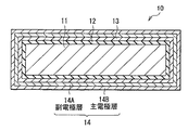
まず、図1および図2を参照して、本発明の一実施の形態に係る電解コンデンサの構成について簡単に説明する。図1および図2は電解コンデンサの主要部(コンデンサ素子10)の構成を表しており、図1は外観構成を示し、図2は図1に示したII−II線に沿った断面構成を拡大して示している。 First, with reference to FIG. 1 and FIG. 2, the structure of the electrolytic capacitor which concerns on one embodiment of this invention is demonstrated easily. 1 and 2 show the configuration of the main part (capacitor element 10) of the electrolytic capacitor, FIG. 1 shows the external configuration, and FIG. 2 is an enlarged cross-sectional configuration along the line II-II shown in FIG. As shown.
この電解コンデンサは、図1および図2に示したコンデンサ素子10に陽極リードおよび陰極リード(いずれも図示せず)が接続され、それらの陽極リードおよび陰極リードの双方が部分的に露出するようにコンデンサ素子10がモールド樹脂(図示せず)により周囲を覆われた構造を有するものである。コンデンサ素子10は、電解コンデンサの主要部として電気的反応を生じるものであり、例えば、図1および図2に示したように、陽極11と、この陽極11の周囲(一端部)を部分的に覆うように配設された誘電体層12と、この誘電体層12を覆うように配設された固体電解質層13と、この固体電解質層13を覆うように配設された陰極14とを含み、すなわち陽極11、誘電体層12、固体電解質層13および陰極14がこの順に積層された積層構造を有している。
In this electrolytic capacitor, an anode lead and a cathode lead (both not shown) are connected to the
陽極11は、拡面化(または粗面化)された表面凹凸構造を有する第1の電極層であり、例えば、アルミニウム(Al)、チタン(Ti)、タンタル(Ta)またはニオブ(Nb)などの弁作用金属を含んで構成されている。具体的には、陽極11は、例えば、アルミニウムまたはチタンなどの金属箔や、タンタルまたはニオブなどの金属焼結体である。なお、拡面化された陽極11の表面凹凸構造の詳細に関しては後述する(図3参照)。
The
誘電体層12は、例えば、弁作用金属により構成された陽極11の表層が陽極酸化されることにより形成された酸化皮膜である。この誘電体層12は、例えば、陽極11がアルミニウムより構成されている場合には、酸化アルミニウム(Al2 O3 )により構成されている。
The
固体電解質層13は、例えば、導電性高分子と、この導電性高分子の導電率を制御するためのドーパントとを含み、すなわち導電性高分子にドーパントが含有(ドープ)された構成を有している。導電性高分子は、例えば、ポリアニリン、ポリピロール、ポリチオフェン、ポリフランおよびこれらの誘導体を含む群のうちの少なくとも1種により構成されており、具体的な一例を挙げれば、ポリチオフェンの誘導体であるポリエチレンジオキシチオフェンなどにより構成されている。また、ドーパントは、例えば、アルキルベンゼンスルホン酸およびその塩、アルキルナフタレンスルホン酸およびその塩、ならびにリン酸を含む群のうちの少なくとも1種により構成されており、具体的な一例を挙げれば、パラトルエンスルホン酸鉄またはイソピロピルナフタレンスルホン酸鉄などにより構成されている。この固体電解質層13を含んでコンデンサ素子10が構成されている電解コンデンサは、いわゆる固体電解コンデンサである。
The
陰極14は、誘電体層12および固体電解質層13を挟んで陽極11に対向配置された第2の電極層である。この陰極14は、本来の電極としての機能の他に、所定の温度範囲内において温度の上昇に応じて抵抗が上昇し、より具体的には抵抗が指数関数的に上昇する機能(いわゆるPTC機能)を有している。このPTC機能を有する陰極14は、例えば、約60℃以上150℃以下の温度範囲内において抵抗が(常温の抵抗と比較して)約1000倍以上上昇するものである。
The
特に、陰極14は、例えば、2層以上の層が積層された積層構造を有しており、その2層以上の層のうちの少なくとも1つの層においてPTC機能を有している。具体的には、陰極14は、例えば、図2に示したように、導電性を確保するための主電極層14Bと、その主電極層14Bと固体電解質層13との間に配設され、主電極層14Bを固体電解質層13に電気的に接合させるための副電極層14Aとを含み、すなわち副電極層14A上に主電極層14Bが配置された2層構造を有している。この陰極14では、例えば、副電極層14AがPTC機能を有しておらず、主電極層14BのみがPTC機能を有している。
In particular, the
副電極層14Aは、例えば、カーボンを含んで構成されている。なお、副電極層14Aは、上記したように主電極層14Bを固体電解質層13に電気的に接合させる機能の他に、例えば、主電極層14Bを固体電解質層13に直接的に接触させた場合に、高温高湿環境中において主電極層14B中の特定成分(例えば銀(Ag))のマイグレーションを防止する機能も有している。
For example, the
主電極層14Bは、例えば、金属を含んで構成されており、具体的には、主成分としての高分子と、この高分子中に保持された副成分としての導電性粒子とを含んで構成されている。すなわち、主電極層14Bは、いわゆるポリマーPTC(P(Polymer )−PTC)層である。この高分子は、例えば、エポキシ樹脂、ポリフッ化ビニリデン(PVDF;Poly Vinylidene Fluoride)およびポリエチレン(PE;Polyethylene)を含む群のうちの少なくとも1種である。また、導電性粒子は、例えば、ニッケル(Ni)、銅(Cu)、アルミニウム(Al)、タングステン(W)、モリブデン(Mo)、亜鉛(Zn)、コバルト(Co)、白金(Pt)、金(Au)および銀(Ag)などの金属粒子、ならびに炭化タングステン(WC)、窒化チタン(TiN)、窒化ジルコニウム(ZrN)、炭化チタン(TiC)、ホウ化チタン(TiB2 )、ケイ化モリブデン(MoSi2 )およびホウ化タンタル(TaB2 )などの導電性セラミック粒子を含む群のうちの少なくとも1種である。
The
なお、参考までに、陽極リードおよび陰極リードは、例えば、いずれも鉄(Fe)または銅(Cu)などの金属や、これらの金属にめっき処理(例えば錫(Sn)めっきまたは錫鉛(SnPb)めっき)が施されためっき処理金属により構成されており、それぞれコンデンサ素子10のうちの陽極11および陰極14に接続されている。モールド樹脂は、例えば、エポキシ樹脂などの絶縁性樹脂により構成されている。
For reference, both the anode lead and the cathode lead are, for example, metals such as iron (Fe) or copper (Cu), and plating treatment (for example, tin (Sn) plating or tin lead (SnPb)) on these metals. It is made of a plated metal subjected to plating, and is connected to the
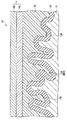
次に、図3を参照して、コンデンサ素子10の詳細な構成について説明する。図3は、図2に示したコンデンサ素子10の断面構成を部分的に拡大して表している。
Next, a detailed configuration of the
コンデンサ素子10では、例えば、図3に示したように、陽極11を覆うように誘電体層12、固体電解質層13および陰極14(副電極層14A,主電極層14B)がこの順に積層されている。このコンデンサ素子10では、陽極11の表面積を増大させることにより高容量化を実現するために、上記したように、その陽極11に拡面化処理(または粗面化処理)が施されており、すなわち陽極11が微細な表面凹凸構造を有している。この陽極11の表面凹凸構造を反映して、その陽極11を覆うように配設されている誘電体層12は微細な凹凸構造を有しており、この微細な凹凸構造を有する誘電体層12を覆うように固体電解質層13および陰極14(副電極層14A,主電極層14B)が配設されている。特に、誘電体層12は、凹凸構造のうちの凹部として複数の細孔12Hを構成しており、固体電解質層13は、誘電体層12により構成された複数の細孔12Hに部分的に入り込んでいる。
In the
図1〜図3に示した電解コンデンサでは、図示しない陽極リードおよび陰極リードを通じてコンデンサ素子10が通電されることにより、そのコンデンサ素子10において電荷が蓄えられる。この際、PTC機能を有する陰極14(主電極層14B)を利用して、短絡時の発熱に起因する電解コンデンサの破壊が防止される。すなわち、例えば、電解コンデンサに過電圧や逆電圧が印加された場合に、誘電体層12が部分的に破損して短絡したことに起因して陽極11と固体電解質層13および陰極14(副電極層14A,主電極層14B)との間に過電流が流れて発熱すると、その短絡時の発熱に基づいて主電極層14Bの温度が上昇することにより抵抗が指数関数的に上昇する結果、コンデンサ素子10中を流れる過電流が抑制されるため、その過電流に起因してコンデンサ素子10が破壊されにくくなる。なお、主電極層14Bの温度が上昇する要因としては、例えば、上記した短絡時の発熱の他に、過電流に起因するジュール熱も含まれる。こののち、主電極層14Bの温度が低下すると、その温度低下に応じて主電極層14Bの抵抗が低下するため、コンデンサ素子10が通電可能な状態に復帰する。
In the electrolytic capacitor shown in FIGS. 1 to 3, electric charge is stored in the
なお、主電極層14BがPTC機能を有する原理は、以下の通りである。すなわち、温度上昇前の段階では、主電極層14Bを構成している高分子中において導電性粒子がチェーン(いわゆる導電パス)を構築しており、そのチェーンが高分子により安定に保持されているため、そのチェーンの存在に基づいて主電極層14Bが低抵抗状態にある。しかしながら、主電極層14Bの温度が上昇すると、高分子の膨張現象に起因してチェーンが切断されるため、主電極層14Bが高抵抗状態になる。もちろん、主電極層14Bの温度が低下すると、高分子の収縮現象に基づいてチェーンが再構築されるため、主電極層14Bが再び低抵抗状態となる。したがって、上記したチェーンの構築・切断・再構築メカニズムを利用して主電極層14Bの抵抗状態が可逆的に変化可能なため、その主電極層14BがPTC機能を有するのである。
The principle that the
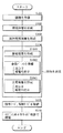
次に、図1〜図4を参照して、本発明の一実施の形態に係る電解コンデンサの製造方法として、図1〜図3に示したコンデンサ素子10を備えた電解コンデンサの製造方法について説明する。図4は、電解コンデンサの製造方法に関する製造工程の流れを説明するためのものである。なお、以下では、電解コンデンサ(コンデンサ素子10)を構成する各構成要素の材質に関しては既に詳細に説明したので、その説明を随時省略するものとする。
Next, with reference to FIGS. 1-4, the manufacturing method of the electrolytic capacitor provided with the capacitor |
電解コンデンサを製造する際には、まず、図1〜図3に示したコンデンサ素子10を形成する。すなわち、まず、陽極11として、例えば、拡面化処理が施された処理済みの弁作用金属箔(例えばアルミニウム箔やチタン箔)、すなわち微細な表面凹凸構造を有する陽極11を準備する(図4;ステップS101)。この陽極11としては、例えば、上記した拡面化処理済みの弁作用金属箔に代えて、タンタルまたはニオブなどの弁作用金属焼結体も使用可能である。なお、陽極11を準備する際には、例えば、上記したように拡面化処理済みの弁作用金属箔を使用する代わりに、未処理の弁作用金属箔を使用し、化学的または電気化学的エッチングを使用して弁作用金属箔に拡面化処理を施すことにより陽極11を形成してもよい。
When manufacturing an electrolytic capacitor, first, the
続いて、陽極11の表層を陽極酸化することにより、その陽極11の周囲を部分的に覆うように酸化皮膜よりなる誘電体層12を形成する(図4;ステップS102)。この誘電体層12としては、例えば、陽極11の形成材料としてアルミニウム箔を使用した場合には、酸化アルミニウムの皮膜により構成されるように誘電体層12を形成可能である。この誘電体層12を形成する際には、例えば、陽極11を化成溶液に浸漬させたのち、その陽極12に電圧を印加することにより陽極酸化反応を進行させるようにする。この化成溶液としては、例えば、ホウ酸アンモニウム、リン酸アンモニウムまたは有機酸アンモニウムなどを含む緩衝溶液を使用し、具体的にはアジピン酸アンモニウム水溶液などを使用する。なお、陽極11に印加する電圧は、例えば、誘電体層12の形成厚さに応じて数V〜数百Vの範囲内で自由に設定可能である。
Subsequently, the surface layer of the
続いて、誘電体層12を覆うように、ドーパントがドープされた導電性高分子を生成することにより、その導電性高分子を含むように固体電解質層13を形成する(図4;ステップS103)。この固体電解質層13を形成する際には、例えば、単量体、ドーパントおよび酸化剤を溶媒に分散させた溶液(単量体溶液)を調製し、その単量体溶液を誘電体層12の表面に塗布したのち、単量体溶液を加熱し、その単量体溶液中の酸化剤を使用して単量体を酸化重合させることにより、導電性高分子を生成する。なお、導電性高分子を生成したのちには、例えば、水、アルコール、アセトンまたはヘキサンなどを使用して導電性高分子を洗浄することにより、導電性高分子に含まれている未重合の単量体、導電性高分子にドープされなかった過剰なドーパント、ならびに使用済みの酸化剤などを洗い流して除去するのが好ましい。単量体溶液の加熱温度および加熱時間は、例えば、単量体の反応性(重合性)や酸化剤の反応性(酸化力)等を考慮して適宜設定可能である。
Subsequently, a conductive polymer doped with a dopant is generated so as to cover the
なお、単量体溶液を調整する際には、単量体として、例えば、アニリン、ピロール、チオフェン、フラン、チオフェンビニレン、イソチアナフテン、アセチレン、p−フェニレン、フェニレンビニレン、メトキシビニレン、メトキシフェニレン、フェニレンスルファイド、フェニレンオキシド、アントラセン、ナフタレン、ピレン、アズレン、セレノフェン、テルロフェンおよびこれらの誘導体を含む群のうちの少なくとも1種を使用し、具体的には3,4−エチレンジオキシチオフェンなどを使用する。 In preparing the monomer solution, examples of the monomer include aniline, pyrrole, thiophene, furan, thiophene vinylene, isothianaphthene, acetylene, p-phenylene, phenylene vinylene, methoxy vinylene, methoxy phenylene, Use at least one of the group comprising phenylene sulfide, phenylene oxide, anthracene, naphthalene, pyrene, azulene, selenophene, tellurophene and their derivatives, specifically 3,4-ethylenedioxythiophene, etc. To do.
また、ドーパントとして、例えば、ドナー型またはアクセプター型のいずれのドーパントも使用可能であり、下記の一連の材料を含む群のうちの少なくとも1種を使用する。ドナー型のドーパントとしては、例えば、リチウム(Li)、ナトリウム(Na)またはカリウム(K)などのアルカリ金属や、カルシウム(Ca)などのアルカリ土類金属等が挙げられる。一方、アクセプター型のドーパントとしては、例えば、塩素(Cl2 )、臭素(Br2 )またはヨウ素(I2 )などのハロゲンや、フッ化リン(PF3 )、フッ化ヒ素(AsF5 )またはフッ化ホウ素(BF3 )などのルイス酸や、フッ化水素(HF)、塩化水素(HCl)、硝酸(HNO3 )、硫酸(H2 SO4 )、リン酸(H3 PO4 )または過塩素酸(HClO4 )などのプロトン酸や、アルキルベンゼンスルホン酸(例えばパラトルエンスルホン酸)、アルキルナフタレンスルホン酸またはこれらの塩(例えばパラトルエンスルホン酸ナトリウムまたはアルキルナフタレンスルホン酸ナトリウム)や、塩化鉄(FeCl3 )、過塩素酸鉄(FeOCl2 )、塩化チタン(TiCl4 )または塩化タングステン(WCl3 )などの遷移金属化合物や、塩素イオン(Cl- )、臭素イオン(Br- )、ヨウ素イオン(I- )、過塩素酸イオン(ClO4 -)、フッ化リンイオン(PF3 -)、フッ化ホウ素イオン(BF3 -)またはフッ化ヒ素イオン(AsF3 -)などの電解質アニオン等が挙げられる。 In addition, as the dopant, for example, either a donor-type or acceptor-type dopant can be used, and at least one of a group including the following series of materials is used. Examples of the donor-type dopant include alkali metals such as lithium (Li), sodium (Na), and potassium (K), and alkaline earth metals such as calcium (Ca). On the other hand, examples of acceptor-type dopants include halogens such as chlorine (Cl 2 ), bromine (Br 2 ), and iodine (I 2 ), phosphorus fluoride (PF 3 ), arsenic fluoride (AsF 5 ), and fluorine. Lewis acids such as boron fluoride (BF 3 ), hydrogen fluoride (HF), hydrogen chloride (HCl), nitric acid (HNO 3 ), sulfuric acid (H 2 SO 4 ), phosphoric acid (H 3 PO 4 ) or perchlorine Protic acids such as acids (HClO 4 ), alkylbenzene sulfonic acids (eg, paratoluene sulfonic acid), alkyl naphthalene sulfonic acids or salts thereof (eg, sodium paratoluene sulfonate or sodium alkyl naphthalene sulfonate), iron chloride (FeCl 3), perchlorate (FeOCl 2), a transition such as titanium chloride (TiCl 4) or tungsten chloride (WCl 3) Or group compound, chlorine ion (Cl -), a bromine ion (Br -), iodide ion (I -), perchlorate ion (ClO 4 -), fluoride phosphorus (PF 3 -), boron fluoride ions (BF 3 − ) or electrolyte anions such as arsenic fluoride ion (AsF 3 − ).
さらに、酸化剤として、例えば、ヨウ素または臭素などのハロゲンや、五フッ化ケイ素(SiF5 )などの金属ハロゲン化物や、硫酸などのプロトン酸や、三酸化硫黄(SO3 )などの酸素化合物や、硫酸セリウム(Ce(SO4 )2 )などの硫酸塩や、過硫酸ナトリウム(Na2 S2 O8 )などの過硫酸塩や、過酸化水素(H2 O2 )などの過酸化物や、アルキルベンゼンスルホン酸塩(例えばパラトルエンスルホン酸鉄)などを使用する。 Further, as the oxidizing agent, for example, halogen such as iodine or bromine, metal halide such as silicon pentafluoride (SiF 5 ), protonic acid such as sulfuric acid, oxygen compound such as sulfur trioxide (SO 3 ), , Sulfates such as cerium sulfate (Ce (SO 4 ) 2 ), persulfates such as sodium persulfate (Na 2 S 2 O 8 ), peroxides such as hydrogen peroxide (H 2 O 2 ) Alkylbenzene sulfonate (for example, iron iron p-toluenesulfonate) is used.
なお、溶媒として、例えば、水や、ブタノールなどの有機溶媒等を使用する。 As the solvent, for example, water or an organic solvent such as butanol is used.
上記した酸化重合反応を経て生成される導電性高分子は、例えば、ポリアニリン、ポリピロール、ポリチオフェン、ポリフラン、ポリチオフェンビニレン、ポリイソチアナフテン、ポリアセチレン、ポリ−p−フェニレン、ポリフェニレンビニレン、ポリメトキシビニレン、ポリメトキシフェニレン、ポリフェニレンスルファイド、ポリフェニレンオキシド、ポリアントラセン、ポリナフタレン、ポリピレン、ポリアズレン、ポリセレノフェン、ポリテルロフェンおよびこれらの誘導体を含む群のうちの少なくとも1種であり、具体的にはポリエチレンジオキシチオフェンである。この導電性高分子としては、例えば、高分子骨格中に一次元的連鎖を有し、かつ電子供与性機能または電子受容性機能(いわゆるドーパミン機能)を有する共役系高分子が好ましい。 The conductive polymer produced through the above oxidative polymerization reaction is, for example, polyaniline, polypyrrole, polythiophene, polyfuran, polythiophene vinylene, polyisothianaphthene, polyacetylene, poly-p-phenylene, polyphenylene vinylene, polymethoxy vinylene, poly At least one member selected from the group comprising methoxyphenylene, polyphenylene sulfide, polyphenylene oxide, polyanthracene, polynaphthalene, polypyrene, polyazulene, polyselenophene, polytellurophene and their derivatives, specifically polyethylenedioxy Thiophene. As the conductive polymer, for example, a conjugated polymer having a one-dimensional chain in the polymer skeleton and having an electron donating function or an electron accepting function (so-called dopamine function) is preferable.
引き続き、電解コンデンサの製造工程について説明する。陽極11、誘電体層12および固体電解質層13がこの順に積層された積層構造を形成したのち、その固体電解質層13を覆うようにPTC機能を有する陰極14を形成する(図4;ステップS104)。
Next, the manufacturing process of the electrolytic capacitor will be described. After forming a laminated structure in which the
この陰極14の形成手順は、例えば、以下の通りである。すなわち、まず、固体電解質層13の表面にカーボンペーストを塗布したのち、そのカーボンペーストを乾燥して膜化することにより、副電極層14Aを形成する(ステップS1041)。続いて、PTC機能を確保するための金属ペーストとして、高分子および導電性粒子を含む金属ペーストを準備する(ステップS1042)。この金属ペーストを準備する際には、例えば、高分子としてエポキシ樹脂、ポリフッ化ビニリデン(PVDF)およびポリエチレン(PE)を含む群のうちの少なくとも1種を使用すると共に、導電性粒子としてニッケル(Ni)、銅(Cu)、アルミニウム(Al)、タングステン(W)、モリブデン(Mo)、亜鉛(Zn)、コバルト(Co)、白金(Pt)、金(Au)および銀(Ag)などの金属粒子、ならびに炭化タングステン(WC)、窒化チタン(TiN)、窒化ジルコニウム(ZrN)、炭化チタン(TiC)、ホウ化チタン(TiB2 )、ケイ化モリブデン(MoSi2 )およびホウ化タンタル(TaB2 )などの導電性セラミック粒子を含む群のうちの少なくとも1種を使用する。この導電性粒子として金属粒子を使用する場合には、例えば、フィラメント状の金属粒子を使用するのが好ましい。特に、金属ペーストを準備する際には、例えば、第1に、高分子が常温で液状である場合には、その液状の高分子をそのまま使用してもよいし、第2に、高分子が常温で液状でない場合には、その高分子を溶媒に溶解させて液状にすることにより使用してもよいし、第3に、高分子が常温で非常に硬く、その高分子を常温で溶解させる適当な溶媒が存在しない場合には、その高分子を加熱して低粘度化させることにより液状に近い状態にして使用してもよい。最後に、副電極層14Aの表面に金属ペーストを供給したのち、その金属ペーストを乾燥して膜化することにより、高分子中に導電性粒子が保持された構成を有するように、PTC機能を有する主電極層14Bを形成する(ステップS1043)。この金属ペーストの供給方法としては、例えば、塗布法(例えばスプレー法、ローラ法またはスピンコート法)、浸漬法(いわゆるディップ法)、あるいは印刷法(例えばスクリーン印刷またはタンポ印刷)などを使用可能である。これにより、副電極層14Aおよび主電極層14Bを含む2層構造を有するように陰極14が形成される。この結果、陽極11、誘電体層12、固体電解質層13および陰極14(副電極層14A,主電極層14B)がこの順に積層された積層構造を有するコンデンサ素子10が完成する。
The formation procedure of the
コンデンサ素子10を形成したのち、このコンデンサ素子10を使用して電解コンデンサを組み立てる。すなわち、例えば、コンデンサ素子10のうちの陽極11に陽極リードを接続させると共に、陰極14に陰極リードを接続させたのち(図4;ステップS105)、陽極リードおよび陰極リードの双方が部分的に露出するようにコンデンサ素子10の周囲をモールド樹脂で被覆する(図4;ステップS106)。これにより、コンデンサ素子10に陽極リードおよび陰極リードが接続され、それらの陽極リードおよび陰極リードの双方が部分的に露出するようにコンデンサ素子10がモールド樹脂により周囲を覆われた構造を有する電解コンデンサが完成する。なお、コンデンサ素子10に陽極リードおよび陰極リードを接続させる際には、例えば、溶接処理またはかしめ加工を使用して直接的に接続させるようにしてもよいし、あるいは導電性接着剤を使用して間接的に接続させるようにしてもよい。
After the
本実施の形態に係る電解コンデンサの製造方法では、PTC機能を有するように陰極14、具体的には主電極層14Bを形成したので、上記したPTC機能の原理に基づき、陰極14のうちの主電極層14BにPTC機能が付与される。この場合には、電解コンデンサにPTC機能を付与するためにコンデンサ素子にPTCサーミスタを接続させており、そのPTCサーミスタの接続工程を要する分だけ電解コンデンサの製造工程が煩雑化すると共に製造工程数が増加してしまう従来の電解コンデンサの製造方法とは異なり、コンデンサ素子10にPTCサーミスタを接続させる工程が不要なため、そのPTCサーミスタの接続工程に起因する電解コンデンサの製造工程の煩雑化および製造工程数の増加が防止される。しかも、このPTC機能を有する主電極層14Bを形成するためには、その主電極層14Bの形成材料としてPTC機能を確保し得ない形成材料に代えてPTC機能を確保し得る形成材料(高分子,導電性粒子)を使用するだけで済み、すなわちPTC機能を確保するための形成材料を使用して主電極層14Bを形成する変更点だけで、PTC機能を有していない現行の電解コンデンサの製造方法をそのまま流用して電解コンデンサを製造することが可能なため、電解コンデンサの製造工程が何ら煩雑化しない。したがって、PTC機能を利用して短絡時の発熱に起因する電解コンデンサの破壊を防止しつつ、その電解コンデンサを容易に製造することが可能となるため、PTC機能を有する電解コンデンサを可能な限り容易に製造することができる。この結果、PTC機能を有する電解コンデンサの製造歩留まりを高めることにより生産性を確保することができる。
In the electrolytic capacitor manufacturing method according to the present embodiment, the
また、上記した他、本実施の形態に係る電解コンデンサでは、陰極14、具体的には陰極14の一部を構成する主電極層14BがPTC機能を有するようにしたので、コンデンサ素子にそのコンデンサ素子以外の構成部品としてPTCサーミスタが外付けされた従来の電解コンデンサとは異なり、コンデンサ素子10のもともとの構成部品である陰極14がPTC機能を有することとなる。この場合には、従来の場合とは異なり、電解コンデンサの構成部品を増やさずにPTC機能が確保されるため、そのPTC機能を確保する上で電解コンデンサの構成の複雑化が防止される。したがって、可能な限り簡素な構成でPTC機能を確保することができる。
In addition to the above, in the electrolytic capacitor according to the present embodiment, the
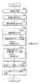
なお、本実施の形態では、PTC機能を有する主電極層14Bを形成する際に、PTC機能を確保するための材料(高分子,導電性粒子)を副電極層14Aの表面に供給して膜化することにより主電極層14Bを形成するようにしたが、必ずしもこれに限られるものではなく、例えば、図5に示したように、副電極層14A上で主電極層14Bを膜化形成する手法に代えて、別途形成した主電極層14Bを副電極層14Aに接続させるようにしてもよい。図5は電解コンデンサの製造方法に関する変形例を説明するためのものであり、図4に対応する製造工程の流れを示している。この電解コンデンサの製造方法では、図1〜図3および図5に示したように、陽極11を準備し(ステップS201)、その陽極11上に誘電体層12および固体電解質層13を形成したのち(ステップS202,S203)、その固体電解質層13上に、別途形成した主電極層14Bを含むように陰極14を形成する(ステップS204)。具体的には、固体電解質層13上に副電極層14Aを形成したのち(ステップS2041)、PTC機能を確保するための材料(高分子,導電性粒子)をシート状に成形することにより導電性高分子シートを形成し(ステップS2042)、その導電性高分子シートを主電極層14Bとして副電極層14Aの表面に接続させることにより(ステップS2043)、副電極層14Aおよび主電極層14Bを含む2層構造を有するように陰極14を形成する。この導電性高分子シートを副電極層14Aに接続させる際には、例えば、副電極層14Aに対する主電極層14Bの接合性を確保するために、接続処理として熱圧着処理を使用するのが好ましい。これにより、陽極11、誘電体層12、固体電解質層13および陰極14(副電極層14A,主電極層14B)がこの順に積層された積層構造を有するコンデンサ素子10が形成される。こののち、コンデンサ素子10のうちの陽極11および陰極14に陽極リードおよび陰極リードをそれぞれ接続させると共に(ステップS205)、陽極リードおよび陰極リードの双方が部分的に露出するようにコンデンサ素子10の周囲をモールド樹脂で被覆することにより(ステップS206)、電解コンデンサが完成する。この場合においても、陰極14のうちの主電極層14BにPTC機能が付与されるため、上記実施の形態と同様の効果を得ることができる。なお、図5に示した電解コンデンサの製造方法に関する上記した以外の手順は、例えば、図4に示した場合と同様である。
In the present embodiment, when the
また、本実施の形態では、陰極14のうちの主電極層14BのみがPTC機能を有するようにしたが、必ずしもこれに限られるものではなく、例えば、主電極層14Bに代えて副電極層14AのみがPTC機能を有するようにしてもよいし、あるいは副電極層14Aおよび主電極層14Bの双方がPTC機能を有するようにしてもよい。主電極層14Bに代えて副電極層14AのみがPTC機能を有するようにする場合には、例えば、副電極層14Aの形成材料(PTC機能を確保するための材料)として高分子および導電性粒子を含むカーボンペーストを使用し、上記実施の形態において主電極層14Bを形成した場合と同様の工程を経て副電極層14Aを形成することにより、その副電極層14AにPTC機能を付与することが可能である。この場合には、例えば、高分子として上記実施の形態において説明した場合と同様の高分子を使用し、導電性粒子としてカーボンブラック(CB;Carbon Black)粒子などのカーボン粒子を使用すると共に、主電極層14の形成材料(PTC機能を確保し得ない材料)として一般的な金属ペースト(例えば銀ペースト等)を使用する。なお、副電極層14Aおよび主電極層14Bの双方がPTC機能を有するようにする場合には、例えば、上記したPTC機能を有する副電極層14AとPTC機能を有する主電極層14Bとを組み合わせればよい。これらの場合においても、陰極14にPTC機能が付与されるため、上記実施の形態と同様の効果を得ることができる。
In the present embodiment, only the
また、本実施の形態では、陰極14が2層構造(副電極層14A,主電極層14B)を有するようにしたが、必ずしもこれに限られるものではなく、その陰極14の積層構造数は2層以上の範囲で自由に変更可能である。この場合においても、陰極14が電極として機能し得るだけの抵抗特性を有すると共にPTC機能を確保し得る限り、上記実施の形態と同様の効果を得ることができる。もちろん、この場合においても、例えば、陰極14の積層構造中の一部の層のみがPTC機能を有するようにしてもよいし、あるいは積層構造中の全ての層がPTC機能を有するようにしてもよい。
In the present embodiment, the
また、本実施の形態では、PTC機能を有する陰極14が積層構造(副電極層14A,主電極層14B)を有するようにしたが、必ずしもこれに限られるものではなく、例えば、図6に示したように、陰極14が単層構造を有するようにしてもよい。この場合には、上記実施の形態において説明したPTC機能を有する主電極層14Bに相当する構成となるように陰極14を構成してもよいし、あるいは上記変形例において説明したPTC機能を有する副電極層14Aに相当する構成となるように陰極14を構成してもよい。ただし、例えば、PTC機能を有する副電極層14Aに含まれる導電性粒子(例えばカーボン粒子)とPTC機能を有する主電極層14Bに含まれる導電性粒子(例えば金属粒子または導電性セラミック粒子)との間で抵抗特性を比較すると、導電性粒子に基づく抵抗値はカーボン粒子よりも金属粒子または導電性セラミック粒子において低くなるため、陰極14がPTC機能と共に電極機能を担うことを考慮すれば、PTC機能を有する主電極層14Bに相当する構成となるように陰極14を構成するのが好ましい。この場合においても、上記実施の形態と同様の効果を得ることができる。なお、図6に示したコンデンサ素子10に関する上記以外の構成的特徴は、例えば、図2に示した場合と同様である。
In the present embodiment, the
次に、本発明の具体的な実施例について説明する。 Next, specific examples of the present invention will be described.
上記実施の形態において説明した電解コンデンサの製造方法を使用して、電解コンデンサを製造した。すなわち、まず、陽極として、銅製の陽極リードが埋設されたタンタル粉末の焼結体(タンタル焼結体)を準備したのち、化成溶液中においてタンタル焼結体に電圧(=5V)を印加し、陽極酸化反応を進行させてタンタル皮膜を形成することにより、誘電体層を形成した。続いて、単量体、ドーパントおよび酸化剤を溶媒に分散させた単量体溶液を準備し、誘電体層を形成済みの陽極を単量体溶液に30秒間に渡って浸漬させることにより、その誘電体層の表面に単量体溶液を付着させたのち、陽極を0.5mm/秒で引き上げて室温乾燥させた。続いて、単量体溶液に浸漬済みの陽極を乾燥器(温度=95℃)に投入して加熱し、その単量体溶液に含まれている酸化剤を使用して単量体を酸化重合させることにより、ドーパントがドープされた導電性高分子を含むように固体電解質層を形成した。続いて、固体電解質層を覆うように副電極層を形成したのち、その副電極層を覆うように主電極層を形成することにより、これらの副電極層および主電極層を含む2層構造を有するように、PTC機能を有する陰極を形成した。この際、陰極のPTC機能として、120℃〜150℃の温度範囲内において抵抗が(常温の抵抗と比較して)約100000倍以上上昇するようにした。これにより、陽極、誘電体層、固体電解質層および陰極(副電極層,主電極層)がこの順に積層された積層構造を有するコンデンサ素子が形成された。最後に、導電性接着剤(銀接着剤)を使用してコンデンサ素子に銅製の陰極リードを接続させたのち、モールド樹脂としてエポキシ樹脂で陽極リードおよび陰極リードが部分的に露出するようにコンデンサ素子の周囲を覆うことにより、電解コンデンサが完成した。 An electrolytic capacitor was manufactured using the electrolytic capacitor manufacturing method described in the above embodiment. That is, first, as a positive electrode, after preparing a tantalum powder sintered body (tantalum sintered body) in which a copper anode lead was embedded, a voltage (= 5 V) was applied to the tantalum sintered body in the chemical conversion solution, A dielectric layer was formed by advancing an anodic oxidation reaction to form a tantalum film. Subsequently, a monomer solution in which a monomer, a dopant and an oxidant are dispersed in a solvent is prepared, and the anode on which the dielectric layer has been formed is immersed in the monomer solution for 30 seconds. After the monomer solution was attached to the surface of the dielectric layer, the anode was pulled up at 0.5 mm / second and dried at room temperature. Subsequently, the anode immersed in the monomer solution is put into a dryer (temperature = 95 ° C.) and heated, and the monomer is oxidatively polymerized using the oxidizing agent contained in the monomer solution. By doing so, a solid electrolyte layer was formed so as to include a conductive polymer doped with a dopant. Subsequently, a sub-electrode layer is formed so as to cover the solid electrolyte layer, and then a main electrode layer is formed so as to cover the sub-electrode layer, thereby forming a two-layer structure including these sub-electrode layer and main electrode layer. Thus, a cathode having a PTC function was formed. At this time, as the PTC function of the cathode, the resistance was increased by about 100,000 times or more (compared to the resistance at normal temperature) within a temperature range of 120 ° C. to 150 ° C. As a result, a capacitor element having a laminated structure in which the anode, the dielectric layer, the solid electrolyte layer, and the cathode (sub-electrode layer, main electrode layer) were laminated in this order was formed. Finally, after connecting the copper cathode lead to the capacitor element using a conductive adhesive (silver adhesive), the capacitor element is so exposed that the anode lead and cathode lead are partially exposed with epoxy resin as the mold resin. The electrolytic capacitor was completed by covering the periphery of the capacitor.
なお、固体電解質層の形成手順は、以下の通りである。すなわち、まず、単量体として3,4−エチレンジオキシチオフェン(バイエル株式会社製Baytron M (商品名))、ならびにドーパント兼酸化剤としてパラトルエンスルホン酸鉄(III)50%ブタノール溶液(バイエル株式会社製Baytron C (商品名))を氷水で十分に冷却したのち、これらの単量体およびドーパント兼酸化剤をそれぞれ0.867g,10.4g秤量し、氷水で冷却しながらマグネチックスターラーで混合・攪拌することにより単量体溶液を調製した。続いて、誘電体層を形成済みの陽極を単量体溶液に浸漬させることにより、その誘電体層の表面に単量体溶液を付着させた。続いて、単量体溶液が付着された誘電体層を室温下において1時間程度放置したのち、その単量体溶液を加熱して単量体を酸化重合させることにより、誘電体層を覆うように導電性高分子としてポリエチレンジオキシチオフェンを生成した。この際、加熱条件は加熱温度=100℃、加熱時間=15分間とした。最後に、蒸留水を使用して導電性高分子を十分に洗浄することにより、未重合の単量体、過剰なドーパント、ならびに使用済みの酸化剤などを洗い流したのち、その導電性高分子を乾燥させた。なお、導電性高分子を形成する際には、上記した導電性高分子の生成手順を3回繰り返し、特に、酸化重合反応の完了時ごとに蒸留水やエタノールを使用して導電性高分子を洗浄することにより、未重合の単量体、余剰なドーパントならびに使用済みの酸化剤を随時除去した。これにより、導電性高分子を含む固体電解質層が形成された。 The procedure for forming the solid electrolyte layer is as follows. First, 3,4-ethylenedioxythiophene as a monomer (Baytron M (trade name) manufactured by Bayer Co., Ltd.) and 50% butanol solution of iron (III) paratoluenesulfonate as a dopant and oxidizing agent (Bayer shares) After sufficiently cooling the company's Baytron C (trade name) with ice water, weigh out 0.867 g and 10.4 g of these monomers and dopant / oxidizer, and mix them with a magnetic stirrer while cooling with ice water. -A monomer solution was prepared by stirring. Subsequently, the monomer solution was adhered to the surface of the dielectric layer by immersing the anode on which the dielectric layer had been formed in the monomer solution. Subsequently, the dielectric layer to which the monomer solution is attached is allowed to stand at room temperature for about 1 hour, and then the monomer solution is heated to oxidatively polymerize the monomer so as to cover the dielectric layer. Polyethylenedioxythiophene was produced as a conductive polymer. At this time, the heating conditions were heating temperature = 100 ° C. and heating time = 15 minutes. Finally, the conductive polymer is thoroughly washed with distilled water to wash away unpolymerized monomers, excess dopant, used oxidant, etc., and then remove the conductive polymer. Dried. When forming the conductive polymer, the above-mentioned procedure for generating the conductive polymer is repeated three times. In particular, the conductive polymer is prepared using distilled water or ethanol every time the oxidative polymerization reaction is completed. By washing, unpolymerized monomer, excess dopant and used oxidizing agent were removed as needed. Thereby, a solid electrolyte layer containing a conductive polymer was formed.
上記した電解コンデンサの製造方法を使用して、PTC機能を有する陰極(副電極層,主電極層)の構成を以下のように変化させながら本発明の電解コンデンサ(実施例1〜3)を製造したのち、その電解コンデンサの諸特性を調べた。なお、本発明の電解コンデンサの諸特性を調べる際には、その性能を比較評価するために、陰極の構成を以下のように設定することにより比較例の電解コンデンサ(比較例)を製造し、その電解コンデンサの諸特性も併せて調べた。 Using the electrolytic capacitor manufacturing method described above, the electrolytic capacitor (Examples 1 to 3) of the present invention is manufactured while changing the configuration of the cathode (sub-electrode layer, main electrode layer) having the PTC function as follows. After that, the characteristics of the electrolytic capacitor were investigated. When investigating the characteristics of the electrolytic capacitor of the present invention, in order to compare and evaluate the performance, the electrolytic capacitor of the comparative example (comparative example) was manufactured by setting the configuration of the cathode as follows. Various characteristics of the electrolytic capacitor were also investigated.
(実施例1)
以下の手順を経ることにより、主電極層のみがPTC機能を有するように陰極を形成した。すなわち、副電極層の形成材料(カーボンペースト)として田中貴金属工業株式会社製のカーボンブラック(CB)ペースト TC−8263を使用し、固体電解質層の表面にカーボンペーストを塗布したのちに125℃で乾燥させることにより、副電極層を形成した。また、高分子および導電性粒子を含む混合材料をシート状に成形することにより導電性高分子シートを作製したのち、その導電性高分子シートを副電極層の表面に接続させることにより主電極層を形成した。この導電性高分子シートを作製する際には、高分子としてAtofina Chemicals 社製のポリフッ化ビニリデン(PVDF) Kynar7201(融点=122℃〜126℃,比重=1.88)を使用すると共に、導電性粒子としてINCO Limited社製のフィラメント状ニッケルパウダ(Ni) Type210(平均粒径=0.5μm〜1.0μm,見かけ密度=0.80g/cm3 ,比表面積=1.50m2 /g〜2.50m2 /g,添加容量比(高分子:導電性粒子)=65:35)を使用し、150℃の混練ミル中で高分子および導電性粒子を加熱溶融して混練させたのち、その混練物を熱プレスして約0.2mmの厚さとなるようにシート状に成形することにより、導電性高分子シートを作製した。この導電性高分子シートの接続処理としては、熱圧着処理を使用した。
(Example 1)
Through the following procedure, the cathode was formed so that only the main electrode layer had the PTC function. That is, carbon black (CB) paste TC-8263 manufactured by Tanaka Kikinzoku Kogyo Co., Ltd. was used as the material for forming the sub-electrode layer (carbon paste), and the carbon paste was applied to the surface of the solid electrolyte layer and then dried at 125 ° C. By doing so, a sub-electrode layer was formed. Also, after forming a conductive polymer sheet by forming a mixed material containing a polymer and conductive particles into a sheet, the main electrode layer is connected to the surface of the sub-electrode layer after the conductive polymer sheet is connected Formed. When this conductive polymer sheet is produced, polyvinylidene fluoride (PVDF) Kynar 7201 (melting point = 122 ° C. to 126 ° C., specific gravity = 1.88) manufactured by Atofina Chemicals is used as the polymer. As the particles, filamentous nickel powder (Ni) Type 210 manufactured by INCO Limited (average particle size = 0.5 μm to 1.0 μm, apparent density = 0.80 g / cm 3 , specific surface area = 1.50 m 2 / g- 2 . 50 m 2 / g, addition capacity ratio (polymer: conductive particles) = 65: 35), the polymer and conductive particles were heated and melted and kneaded in a kneading mill at 150 ° C., and then kneaded. The object was hot-pressed and formed into a sheet shape having a thickness of about 0.2 mm to produce a conductive polymer sheet. As a connection process for the conductive polymer sheet, a thermocompression bonding process was used.
(実施例2)
高分子として日本ポリエチレン株式会社製の直鎖状低密度ポリエチレン(L−LDPE;Linear-Low Density Polyethylene ) UJ960(融点=127℃,比重=0.921)を使用すると共に、導電性粒子として日本新金属株式会社製の炭化チタン(TiC) TiC−01(平均粒径=0.9μm〜1.5μm,添加容量比(高分子:導電性粒子)=68:32)を使用して導電性高分子シートを作製した点を除き、実施例1と同様の手順を経ることにより陰極を形成した。
(Example 2)
As a polymer, Nippon Low Polyethylene (L-LDPE) UJ960 (melting point = 127 ° C, specific gravity = 0.921) manufactured by Nippon Polyethylene Co., Ltd. is used, and Nippon Shin Conductive polymer using titanium carbide (TiC) TiC-01 (average particle size = 0.9 μm to 1.5 μm, additive volume ratio (polymer: conductive particles) = 68: 32) manufactured by Metal Co., Ltd. A cathode was formed by the same procedure as in Example 1 except that the sheet was produced.
(実施例3)
以下の手順を経ることにより、副電極層のみがPTC機能を有するように陰極を形成した。すなわち、高分子および導電性粒子を含む混合材料をシート状に成形することにより導電性高分子シートを作製したのち、その導電性高分子シートを固体電解質層の表面に接続させることにより、副電極層を形成した。この導電性高分子シートを作製する際には、高分子として日本ポリエチレン株式会社社製の高密度ポリエチレン(HDPE;High Density Polyethylene ) HY540(融点=135℃,比重=0.961)を使用すると共に、導電性粒子としてColumbian Chemicals Company 社製のカーボンブラック(CB) Raven430(添加容量比(高分子:導電性粒子)=67:33)を使用し、150℃の混練ミル中で高分子および導電性粒子を加熱溶融して混練させたのち、その混練物を熱プレスして約0.2mmの厚さとなるようにシート状に成形することにより、導電性高分子シートを作製した。この導電性高分子シートの接続処理としては、熱圧着処理を使用した。また、主電極層の形成材料(金属ペースト)として田中貴金属工業株式会社製の銀ペースト NH−1429Nを使用し、副電極層の表面に銀ペーストを塗布したのちに乾燥させることにより、主電極層を形成した。
(Example 3)
Through the following procedure, the cathode was formed so that only the sub-electrode layer had the PTC function. That is, after forming a conductive polymer sheet by forming a mixed material containing a polymer and conductive particles into a sheet shape, the conductive polymer sheet is connected to the surface of the solid electrolyte layer, thereby forming a sub-electrode. A layer was formed. When producing this conductive polymer sheet, high-density polyethylene (HDPE; High Density Polyethylene) HY540 (melting point = 135 ° C, specific gravity = 0.961) manufactured by Nippon Polyethylene Co., Ltd. is used as the polymer. Using carbon black (CB) Raven430 (additional capacity ratio (polymer: conductive particles) = 67: 33) manufactured by Columbian Chemicals Company as the conductive particles, the polymer and the conductive materials were mixed in a kneading mill at 150 ° C. After the particles were melted by heating and kneaded, the kneaded product was hot-pressed and formed into a sheet shape having a thickness of about 0.2 mm, thereby producing a conductive polymer sheet. As a connection process for the conductive polymer sheet, a thermocompression bonding process was used. In addition, a silver paste NH-1429N manufactured by Tanaka Kikinzoku Kogyo Co., Ltd. is used as a material for forming the main electrode layer (metal paste), and the main electrode layer is dried by applying the silver paste to the surface of the sub-electrode layer and then drying it. Formed.
(比較例)
以下の手順を経ることにより、PTC機能を有しないように陰極を形成した。すなわち、副電極層の形成材料として実施例1で使用したカーボンペーストを使用し、そのカーボンペーストを固体電解質層の表面に塗布したのちに125℃で乾燥させることにより副電極層を形成すると共に、主電極層の形成材料として実施例3で使用した銀ペーストを使用し、その銀ペーストを副電極層の表面に塗布したのちに乾燥させることにより主電極層を形成した。
(Comparative example)
Through the following procedure, a cathode was formed so as not to have a PTC function. That is, using the carbon paste used in Example 1 as a material for forming the sub-electrode layer, applying the carbon paste to the surface of the solid electrolyte layer, and then drying at 125 ° C. to form the sub-electrode layer, The silver paste used in Example 3 was used as a material for forming the main electrode layer, and the silver paste was applied to the surface of the sub-electrode layer and then dried to form the main electrode layer.
これらの実施例1〜3および比較例の電解コンデンサに関して作動試験を実施することにより、各電解コンデンサの作動特性を調べたところ、表1に示した結果が得られた。表1は電解コンデンサの作動特性を表しており、各電解コンデンサの作動特性結果を「評価」として「OK」または「NG」と示している。電解コンデンサの作動状況を調べる際には、各電解コンデンサに逆電圧(=30V)を印加したのちに目視で観察することにより、発火しなかったものを「OK」、発火したものを「NG」としてそれぞれ判定した。なお、表1には、参考までに、陰極(副電極層,主電極層)の構成(高分子,導電性粒子)、ならびに副電極層および主電極層のPTC機能の有無を併せて示している。 When the operation characteristics of each electrolytic capacitor were examined by conducting an operation test on the electrolytic capacitors of Examples 1 to 3 and the comparative example, the results shown in Table 1 were obtained. Table 1 shows the operating characteristics of the electrolytic capacitors, and the results of the operating characteristics of each electrolytic capacitor are shown as “OK” or “NG” as “evaluation”. When investigating the operating conditions of the electrolytic capacitors, by applying a reverse voltage (= 30V) to each electrolytic capacitor and visually observing it, “OK” indicates that no ignition occurred, and “NG” indicates that the ignition occurred. Each was judged as. For reference, Table 1 also shows the configuration (polymer, conductive particles) of the cathode (sub-electrode layer, main electrode layer) and the presence / absence of the PTC function of the sub-electrode layer and main electrode layer. Yes.
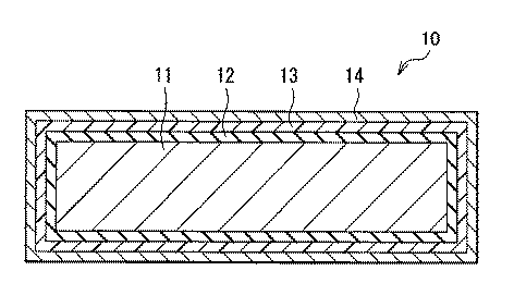
表1に示した結果から判るように、主電極層がPTC機能を有する実施例1,2の電解コンデンサおよび副電極層がPTC機能を有する実施例3の電解コンデンサでは、逆電圧の印加に応じて短絡が生じたことに起因して瞬間的に過電流(短絡電流)が流れたが、PTC機能を利用して過電流が直ちに抑制されたために発火しなかった。なお、実施例1〜3の電解コンデンサに関して、PTC機能を有する主電極層または副電極層の抵抗変化を調べたところ、その抵抗は温度上昇に応じて1000倍以上上昇しており、PTC機能を発揮し得るだけの十分な抵抗変化率を有していた。これに対して、PTC機能を有していない比較例の電解コンデンサでは、逆電圧の印加に応じて短絡が生じたことに起因して過電流が流れると、PTC機能を有していないために過電流が継続的に流れることにより発熱したため、最終的に発火した。このことから、実施例1〜3の電解コンデンサでは、PTC機能を利用することにより短絡時の発熱に起因する破壊を防止可能であることが確認された。 As can be seen from the results shown in Table 1, in the electrolytic capacitors of Examples 1 and 2 in which the main electrode layer has the PTC function and the electrolytic capacitor in Example 3 in which the sub-electrode layer has the PTC function, the reverse voltage is applied. Although an overcurrent (short circuit current) flowed instantaneously due to the occurrence of a short circuit, the overcurrent was immediately suppressed using the PTC function, and no ignition occurred. Regarding the electrolytic capacitors of Examples 1 to 3, when the resistance change of the main electrode layer or the sub electrode layer having the PTC function was examined, the resistance increased by 1000 times or more according to the temperature rise, and the PTC function was improved. It had a sufficient resistance change rate that could be exerted. On the other hand, in the electrolytic capacitor of the comparative example that does not have the PTC function, when an overcurrent flows due to the occurrence of a short circuit in response to application of the reverse voltage, the PTC function is not provided. Since overheating continued to generate heat, it eventually ignited. From this, it was confirmed that the electrolytic capacitors of Examples 1 to 3 can prevent breakage due to heat generation at the time of short circuit by using the PTC function.
なお、具体的にデータを示した上で説明しないが、副電極層および主電極層の双方がPTC機能を有するように製造した電解コンデンサ、具体的には実施例1,2の副電極層(PTC機能無)を実施例3の副電極層(PTC機能有)に置き換えた電解コンデンサ、あるいは実施例3の主電極層(PTC機能無)を実施例1,2の主電極層(PTC機能有)に置き換えた電解コンデンサの諸特性を調べたところ、いずれの電解コンデンサにおいても実施例1〜3の電解コンデンサに関して得られた結果と同様の結果が得られた。このことから、副電極層および主電極層の双方がPTC機能を有するようにした場合においても、電解コンデンサを安定に製造可能であることが確認された。 In addition, although it does not demonstrate after showing data concretely, the electrolytic capacitor manufactured so that both a subelectrode layer and a main electrode layer may have a PTC function, specifically, the subelectrode layer of Examples 1 and 2 ( An electrolytic capacitor obtained by replacing the PTC function) with the sub-electrode layer (with PTC function) of Example 3, or the main electrode layer (without PTC function) of Example 3 with the main electrode layer (with PTC function) of Examples 1 and 2. When the characteristics of the electrolytic capacitor replaced with) were examined, the results similar to those obtained with respect to the electrolytic capacitors of Examples 1 to 3 were obtained in any electrolytic capacitor. From this, it was confirmed that even when both the sub electrode layer and the main electrode layer have the PTC function, the electrolytic capacitor can be stably manufactured.
以上、実施の形態および実施例を挙げて本発明を説明したが、本発明はこれらの実施の形態や実施例に限定されず、PTC機能を有する陰極を備えるように電解コンデンサを構成または製造可能な限り、その電解コンデンサの構成、材質または寸法、ならびに電解コンデンサの製造手順等は自由に変更可能である。 Although the present invention has been described with reference to the embodiments and examples, the present invention is not limited to these embodiments and examples, and an electrolytic capacitor can be configured or manufactured to include a cathode having a PTC function. As long as the configuration, material or dimensions of the electrolytic capacitor, and the manufacturing procedure of the electrolytic capacitor can be freely changed.
本発明に係る電解コンデンサおよびその製造方法は、電気的反応を生じる主要部(コンデンサ素子)が固体材料(導電性高分子)を含んで構成された固体電解コンデンサおよびその製造方法に適用することが可能である。 The electrolytic capacitor and the manufacturing method thereof according to the present invention can be applied to a solid electrolytic capacitor in which a main part (capacitor element) that generates an electrical reaction includes a solid material (conductive polymer) and a manufacturing method thereof. Is possible.
10…コンデンサ素子、11…陽極、12…誘電体層、12H…細孔、13…固体電解質層、14…陰極、14A…副電極層、14B…主電極層。
DESCRIPTION OF
Claims (11)
ことを特徴とする電解コンデンサ。 The first electrode layer, the dielectric layer, the solid electrolyte layer, and the second electrode layer whose resistance increases with an increase in temperature within a predetermined temperature range are stacked in this order. An electrolytic capacitor characterized by that.
その2層以上の層のうちの少なくとも1つの層において、所定の温度範囲内において温度の上昇に応じて抵抗が上昇する
ことを特徴とする請求項1記載の電解コンデンサ。 The second electrode layer has a laminated structure in which two or more layers are laminated;
2. The electrolytic capacitor according to claim 1, wherein in at least one of the two or more layers, the resistance increases as the temperature increases within a predetermined temperature range.
ことを特徴とする請求項2記載の電解コンデンサ。 The second electrode layer is disposed between a main electrode layer for ensuring conductivity and the main electrode layer and the solid electrolyte layer, and the main electrode layer is electrically connected to the solid electrolyte layer. The electrolytic capacitor according to claim 2, wherein the electrolytic capacitor has a two-layer structure including a sub-electrode layer for bonding.
ことを特徴とする請求項3記載の電解コンデンサ。 The electrolytic capacitor according to claim 3, wherein the main electrode layer includes a metal, and the sub electrode layer includes carbon.
ことを特徴とする請求項1記載の電解コンデンサ。 The electrolytic capacitor according to claim 1, wherein the second electrode layer has a single-layer structure.
ことを特徴とする請求項1ないし請求項5のいずれか1項に記載の電解コンデンサ。 The said 2nd electrode layer is comprised including the polymer and the electroconductive particle hold | maintained in the polymer. The one of the Claims 1 thru | or 5 characterized by the above-mentioned. Electrolytic capacitor.
ことを特徴とする請求項1ないし請求項6のいずれか1項に記載の電解コンデンサ。 7. The electrolysis according to claim 1, wherein the second electrode layer has a resistance increased by 1000 times or more within a temperature range of 60 ° C. or more and 150 ° C. or less. Capacitor.
前記誘電体層が、前記第1の電極層の表層が陽極酸化されることにより形成されたものである
ことを特徴とする請求項1ないし請求項7のいずれか1項に記載の電解コンデンサ。 The first electrode layer comprises a valve metal;
The electrolytic capacitor according to any one of claims 1 to 7, wherein the dielectric layer is formed by anodizing a surface layer of the first electrode layer.
ことを特徴とする電解コンデンサの製造方法。 The first electrode layer, the dielectric layer, and the solid electrolyte layer are stacked in this order on the solid electrolyte layer so that the resistance increases as the temperature rises within a predetermined temperature range. 2. An electrolytic capacitor manufacturing method, comprising: forming an electrode layer of 2;
ことを特徴とする請求項9記載の電解コンデンサの製造方法。 The method for manufacturing an electrolytic capacitor according to claim 9, wherein the second electrode layer is formed so as to include a polymer and conductive particles held in the polymer.
ことを特徴とする請求項9または請求項10に記載の電解コンデンサの製造方法。 11. The method for manufacturing an electrolytic capacitor according to claim 9, wherein the second electrode layer is formed so that the resistance increases 1000 times or more within a temperature range of 60 ° C. or more and 150 ° C. or less. .
Priority Applications (3)
| Application Number | Priority Date | Filing Date | Title |
|---|---|---|---|
| JP2004105231A JP2005294420A (en) | 2004-03-31 | 2004-03-31 | Electrolytic capacitor or its manufacturing method |
| US11/089,227 US7218506B2 (en) | 2004-03-31 | 2005-03-25 | Electrolytic capacitor and method of manufacturing the same |
| US11/634,126 US7245479B2 (en) | 2004-03-31 | 2006-12-06 | Electrolytic capacitor and method of manufacturing the same |
Applications Claiming Priority (1)
| Application Number | Priority Date | Filing Date | Title |
|---|---|---|---|
| JP2004105231A JP2005294420A (en) | 2004-03-31 | 2004-03-31 | Electrolytic capacitor or its manufacturing method |
Publications (1)
| Publication Number | Publication Date |
|---|---|
| JP2005294420A true JP2005294420A (en) | 2005-10-20 |
Family
ID=35327037
Family Applications (1)
| Application Number | Title | Priority Date | Filing Date |
|---|---|---|---|
| JP2004105231A Pending JP2005294420A (en) | 2004-03-31 | 2004-03-31 | Electrolytic capacitor or its manufacturing method |
Country Status (1)
| Country | Link |
|---|---|
| JP (1) | JP2005294420A (en) |
-
2004
- 2004-03-31 JP JP2004105231A patent/JP2005294420A/en active Pending
Similar Documents
| Publication | Publication Date | Title |
|---|---|---|
| US7218506B2 (en) | Electrolytic capacitor and method of manufacturing the same | |
| TWI478189B (en) | Solid electrolytic capacitor and method of manufacturing thereof | |
| JP4600398B2 (en) | Solid electrolytic capacitor and manufacturing method thereof | |
| CN101484958B (en) | Solid electrolytic capacitor | |
| JP2003059763A (en) | Method for manufacturing solid electrolytic capacitor | |
| CN101681726B (en) | Conductive paste for solid electrolytic capacitor electrode and process for producing solid electrolytic capacitor electrode using the same | |
| JP6142292B2 (en) | Solid electrolytic capacitor | |
| WO2018043063A1 (en) | Electrolytic capacitor and method for producing same | |
| JP5321964B2 (en) | Solid electrolytic capacitor and manufacturing method thereof | |
| JP4539141B2 (en) | Electrolytic capacitor and manufacturing method thereof | |
| CN115621048A (en) | Solid electrolytic capacitor and method for manufacturing solid electrolytic capacitor | |
| JP4655339B2 (en) | Solid electrolytic capacitor element and manufacturing method thereof | |
| JP4937170B2 (en) | Solid electrolytic capacitor | |
| JP2005294522A (en) | Electrolytic capacitor and its manufacturing method | |
| JP2001110685A (en) | Solid electrolytic capacitors | |
| JP2003289015A (en) | Polymer solid electrolytic capacitors | |
| JP4592822B1 (en) | Solid electrolytic capacitor | |
| JP2011243898A (en) | Solid electrolytic capacitor | |
| JP2012153867A (en) | Conductive composition as well as production method therefor, and capacitor prepared using the conductive composition | |
| JP2005294507A (en) | Electrolytic capacitor and its manufacturing method | |
| JP2005135853A (en) | Solid electrolyte, electrolytic capacitor and its manufacturing method | |
| JP2005191126A (en) | Method for forming conductive polymer, and method for producing electronic component | |
| JP2006135191A (en) | Solid electrolytic capacitor and manufacturing method thereof | |
| JPH10289839A (en) | Method for manufacturing solid electrolytic capacitor | |
| JP2005136336A (en) | Solid electrolyte and its manufacturing method, and electrolytic capacitor and its manufacturing method |
Legal Events
| Date | Code | Title | Description |
|---|---|---|---|
| A621 | Written request for application examination |
Effective date: 20061116 Free format text: JAPANESE INTERMEDIATE CODE: A621 |
|
| A977 | Report on retrieval |
Free format text: JAPANESE INTERMEDIATE CODE: A971007 Effective date: 20090910 |
|
| A131 | Notification of reasons for refusal |
Effective date: 20090916 Free format text: JAPANESE INTERMEDIATE CODE: A131 |
|
| A02 | Decision of refusal |
Effective date: 20100126 Free format text: JAPANESE INTERMEDIATE CODE: A02 |