JP2005294310A - Energy beam irradiation apparatus and pattern making method using the same - Google Patents
Energy beam irradiation apparatus and pattern making method using the same Download PDFInfo
- Publication number
- JP2005294310A JP2005294310A JP2004103051A JP2004103051A JP2005294310A JP 2005294310 A JP2005294310 A JP 2005294310A JP 2004103051 A JP2004103051 A JP 2004103051A JP 2004103051 A JP2004103051 A JP 2004103051A JP 2005294310 A JP2005294310 A JP 2005294310A
- Authority
- JP
- Japan
- Prior art keywords
- energy beam
- energy
- irradiated
- irradiation
- chamber
- Prior art date
- Legal status (The legal status is an assumption and is not a legal conclusion. Google has not performed a legal analysis and makes no representation as to the accuracy of the status listed.)
- Granted
Links
Images

Landscapes
- Welding Or Cutting Using Electron Beams (AREA)
- Electron Beam Exposure (AREA)
Abstract
【課題】 チタンやケイ素等の薄膜を用いることなく、エネルギー線発生部とエネルギー線照射部とを隔絶できるエネルギー線照射装置を提供し、該装置を用いたエネルギー線照射方法およびパタン作成方法を提供する。
【解決手段】 エネルギー線を発生するエネルギー線発生部、被照射体にエネルギー線を照射する照射部、前記エネルギー線発生部と前記照射部との間に配置された差動排気部、を備えることを特徴とするエネルギー線照射装置を用いる。
【選択図】 図3
PROBLEM TO BE SOLVED: To provide an energy ray irradiation apparatus capable of isolating an energy ray generation part and an energy ray irradiation part without using a thin film such as titanium or silicon, and to provide an energy ray irradiation method and a pattern creation method using the apparatus To do.
An energy beam generating unit that generates an energy beam, an irradiation unit that irradiates an irradiated object with an energy beam, and a differential exhaust unit that is disposed between the energy beam generating unit and the irradiation unit. The energy beam irradiation apparatus characterized by these is used.
[Selection] Figure 3
Description
本発明は、差動排気機構を備えたエネルギー線照射装置およびそれを用いたエネルギー線照射方法、パタン作成方法に関する。 The present invention relates to an energy beam irradiation apparatus including a differential pumping mechanism, an energy beam irradiation method using the same, and a pattern creation method.
エネルギー線を被照射体に照射するエネルギー線照射装置においては、エネルギー線の発生部を真空に近い減圧にすることが必要となる。このため、被照射体にエネルギー線を照射する照射部も真空に近い減圧にすることが必要であった。 In an energy beam irradiation apparatus that irradiates an irradiated body with an energy beam, it is necessary to reduce the energy beam generation part to a vacuum close to a vacuum. For this reason, it has been necessary to reduce the pressure of the irradiation part that irradiates the irradiated object with energy rays to a level close to vacuum.
しかし、被照射体にエネルギー線を照射するには、照射部の搬入口を開く、搬入口から被照射体を搬入する、搬入口を閉じる、照射部の空気を排気して減圧する、エネルギー線を照射する、照射部を常圧に戻す、搬入口を開く、被照射体を取り出す、という一連の工程を必要とし、作業効率が著しく低くなるという問題がある。また、被照射体によっては、減圧下で変形等を起こすものもあり、使用できる被照射体も限られていた。 However, in order to irradiate the irradiated object with energy rays, the irradiation port of the irradiation unit is opened, the irradiation target is loaded from the loading port, the loading port is closed, the air of the irradiation unit is exhausted, and the pressure is reduced. There is a problem that a series of steps of irradiating, irradiating the irradiation part to normal pressure, opening the carry-in port, and taking out the irradiated object are required, and the working efficiency is remarkably lowered. In addition, some irradiated bodies may be deformed under reduced pressure, and usable irradiated bodies are limited.
これらの問題を解決する手段として、電子線発生部と照射部とをチタンやケイ素等の薄膜により隔絶するものが知られている。これにより、電子線発生部を真空に保ったまま、照射部を常圧にして被照射体に電子線を照射することができるようになる(特許文献1参照)。 As means for solving these problems, an electron beam generating part and an irradiating part are isolated by a thin film such as titanium or silicon. Thereby, it becomes possible to irradiate the irradiated object with the electron beam while keeping the electron beam generating part in a vacuum while setting the irradiation part to normal pressure (see Patent Document 1).
しかし、これは電子線にのみ用いることができ、イオン等のエネルギー線に用いることができなかった。また、薄膜を介して電子線を照射するため、20keV程度のエネルギーロスを生じ、そのため、電子線を20keV以上に加速する必要があった。さらに、薄膜の損傷を防止するために絶えず電子線を走査しておく必要があり、装置構成が複雑になるという問題があった。また、薄膜に電子線を照射することにより、X線が多量に発生するという問題もあった。
本発明の課題は、チタンやケイ素等の薄膜を用いることなく、エネルギー線発生部とエネルギー線照射部とを隔絶できるエネルギー線照射装置を提供し、該装置を用いたエネルギー線照射方法およびパタン作成方法を提供することにある。 An object of the present invention is to provide an energy beam irradiation apparatus capable of isolating an energy beam generation unit and an energy beam irradiation unit without using a thin film such as titanium or silicon, and an energy beam irradiation method and pattern creation using the device It is to provide a method.
本発明は、エネルギー発生部と照射部との間に差動排気部を配置することにより、上記課題を解決するものである。 This invention solves the said subject by arrange | positioning a differential exhaust_gas | exhaustion part between an energy generation part and an irradiation part.
即ち、本発明は、エネルギー線を発生するエネルギー線発生部、被照射体にエネルギー線を照射する照射部、前記エネルギー線発生部と前記照射部との間に配置された差動排気部、を備えることを特徴とするエネルギー線照射装置である。 That is, the present invention includes an energy beam generating unit that generates an energy beam, an irradiation unit that irradiates an irradiated object with an energy beam, and a differential exhaust unit disposed between the energy beam generating unit and the irradiation unit. It is an energy beam irradiation apparatus characterized by providing.
また、本発明は、差動排気部が、エネルギー線の進行方向に対して斜めに横切る遮蔽板により、第1のチャンバーと第2のチャンバーを形成するように仕切られており、第1のチャンバーおよび第2のチャンバーがそれぞれ排気口を備えていることを特徴とする、上記の装置である。 Further, according to the present invention, the differential exhaust portion is partitioned so as to form the first chamber and the second chamber by a shielding plate that crosses obliquely with respect to the traveling direction of the energy beam, and the first chamber The apparatus as described above, wherein the second chamber and the second chamber each have an exhaust port.
また、本発明は、複数の差動排気部を有することを特徴とする、上記のエネルギー線照射装置である。 Moreover, this invention is said energy beam irradiation apparatus characterized by having a some differential exhaust part.
また、本発明は、エネルギー線が、電子線、イオン線、および中性粒子線からなる群より選択される、上記の装置である。 Moreover, this invention is said apparatus whose energy beam is selected from the group which consists of an electron beam, an ion beam, and a neutral particle beam.
また、本発明は、エネルギー線発生部が、100〜1000mmの長さを有するエネルギー線放出体を備えることを特徴とする、上記の装置である。 Moreover, this invention is said apparatus characterized by the energy-beam generating part being provided with the energy-beam emitter which has a length of 100-1000 mm.
また、本発明は、エネルギー線発生部が、エネルギー線放出体の厚さ若しくは直径に対して200倍以上の長さを有するエネルギー線放出体を備えることを特徴とする、上記の装置である。 The present invention is also the above apparatus, wherein the energy beam generator includes an energy beam emitter having a length of 200 times or more with respect to the thickness or diameter of the energy beam emitter.
また、本発明は、エネルギー線発生部が、直線状を維持するように端部が引っ張られているエネルギー線放出体を備えることを特徴とする、上記の装置である。 In addition, the present invention is the apparatus described above, wherein the energy beam generating unit includes an energy beam emitter whose end is pulled so as to maintain a linear shape.
また、本発明は、エネルギー線発生部がピアス型のエネルギー線発生装置を備えることを特徴とする、上記の装置である。 Moreover, this invention is said apparatus characterized by the energy-beam generating part being provided with a pierce-type energy-beam generator.
また、本発明は、エネルギー線発生部がピアス型の電子銃を備えることを特徴とする、上記の装置である。 Moreover, this invention is said apparatus characterized by the energy-beam generating part being provided with a piercing-type electron gun.
また、本発明は、エネルギー線発生部が線状または矩形のエネルギー線放出体を備えることを特徴とする、上記の装置である。 Moreover, this invention is said apparatus characterized by the energy-beam generating part being provided with the linear or rectangular energy-beam emitter.
また、本発明は、エネルギー線の照射エネルギーを変化させることができる機構を有することを特徴とする、上記の装置である。 Moreover, this invention is said apparatus characterized by having a mechanism which can change the irradiation energy of an energy ray.
また、本発明は、カソードとアノードとの間の電圧を一定に保ったままカソードの電圧を変化させる機構を有することを特徴とする、上記の装置である。 In addition, the present invention is the apparatus described above, characterized in that it has a mechanism for changing the voltage of the cathode while keeping the voltage between the cathode and the anode constant.
また、本発明は、反射電極に、カソードと同電位〜マイナス100Vの電位を印加する機構を有することを特徴とする、上記の装置である。 In addition, the present invention is the apparatus described above, which has a mechanism for applying a potential of the same potential to minus 100 V as the cathode to the reflective electrode.
また、本発明は、カソードに通電する電気量と、ウェネルトへのバイアス電位を変化させる機構を有することを特徴とする、上記の装置である。 In addition, the present invention is the above apparatus characterized by having a mechanism for changing the amount of electricity supplied to the cathode and the bias potential to Wehnelt.
また、本発明は、上記の装置を用いて、被照射体にエネルギー線を照射する方法である。 Moreover, this invention is a method of irradiating an irradiated body with an energy ray using said apparatus.
また、本発明は、被照射体に照射されるエネルギー線のエネルギーが100keV以下であることを特徴とする、上記の方法である。 Moreover, this invention is said method characterized by the energy of the energy beam irradiated to a to-be-irradiated body being 100 keV or less.
また、本発明は、0.1Pa以上の圧力下でエネルギー線を照射することを特徴とする、上記の方法である。 Moreover, this invention is said method characterized by irradiating an energy ray under the pressure of 0.1 Pa or more.
また、本発明は、特定の気体の存在下でエネルギー線を照射することを特徴とする、上記の方法である。 Moreover, this invention is said method characterized by irradiating an energy ray in presence of specific gas.
また、本発明は、エネルギー線の断面形状の短軸方向に被照射体を移動させることによりエネルギー線を照射することを特徴とする、上記の方法である。 Moreover, this invention is said method characterized by irradiating an energy ray by moving a to-be-irradiated body to the short-axis direction of the cross-sectional shape of an energy ray.
また、本発明は、被照射体の移動速度を変化させることにより、被照射体に照射されるエネルギー線量を変化させることを特徴とする、上記の方法である。 Further, the present invention is the above method, wherein the energy dose irradiated to the irradiated object is changed by changing the moving speed of the irradiated object.
また、本発明は、基材表面をパタン化処理した後に、上記の装置、および/または、上記の方法を用いてエネルギー線を照射することを特徴とする、パタン作成方法である。 Moreover, this invention is a pattern preparation method characterized by irradiating an energy beam using said apparatus and / or said method, after patterning the surface of a base material.
また、本発明は、パタン化処理が、レジスト材および/または低誘電体を含む材料により行われることを特徴とする、上記のパタン作成方法である。 Further, the present invention is the above-described pattern creation method, wherein the patterning process is performed using a resist material and / or a material containing a low dielectric material.
また、本発明は、基材表面をパタン化処理した後に、基材を80〜150℃に加温し、エネルギー線を照射することを特徴とする、上記の方法である。 Moreover, this invention is said method characterized by heating a base material to 80-150 degreeC, and irradiating an energy beam after patterning the base material surface.
また、本発明は、パタンの線幅が10μm以下であることを特徴とする、上記の方法である。 Further, the present invention is the above method, wherein the line width of the pattern is 10 μm or less.
また、本発明は、パタン化処理を行う前に、基材を清浄化することを特徴とする、上記の方法である。 Moreover, this invention is said method characterized by cleaning a base material before performing a patterning process.
また、本発明は、上記の装置、および/または、上記の方法を用いて、半導体を製造する方法である。 Moreover, this invention is a method of manufacturing a semiconductor using said apparatus and / or said method.
また、本発明は、エネルギー線の照射に用いる差動排気装置であって、エネルギー線の進行方向に対して斜めに横切る遮蔽板により、前記差動排気装置が第1のチャンバーと第2のチャンバーを形成するように仕切られており、第1のチャンバーおよび第2のチャンバーがそれぞれ排気口を備えていることを特徴とする、差動排気装置である。 The present invention is also a differential exhaust device used for energy beam irradiation, wherein the differential exhaust device has a first chamber and a second chamber by means of a shielding plate that obliquely crosses the traveling direction of the energy beam. The differential exhaust device is characterized in that the first chamber and the second chamber are each provided with an exhaust port.
本発明により、チタンやケイ素等の薄膜を用いることなくエネルギー線発生部とエネルギー線照射部とを隔絶できるエネルギー線照射装置を提供できる。 According to the present invention, it is possible to provide an energy beam irradiation apparatus capable of isolating an energy beam generation unit and an energy beam irradiation unit without using a thin film such as titanium or silicon.
以下、図面を参照して本発明を説明する。
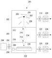
図1は、エネルギー線として電子線を用いた場合の、本発明のエネルギー線照射装置を示す図である。図1において、本発明の電子線照射装置201は、電子線発生部202、差動排気部203、照射部204の順で配置されている。電子発生部202は、反射電極205、カソード206、ウェネルト207、アノード208を備えている。また、電子線発生部202は、バルブ218を介して排気機構としてターボ分子ポンプ220に接続され、ターボ分子ポンプ220は、図示しない荒引きポンプに接続されている。差動排気部203は、差動排気口210を有する遮蔽板212により電子線発生部202と隔絶されており、差動排気口214を有する遮蔽板216により照射部204と隔絶されている。また、差動排気部203は、バルブ222を介してターボ分子ポンプ224に接続され、ターボ分子ポンプ224は、図示しない荒引きポンプに接続されている。照射部204は、ウエハ230を保持するステージ232を備えており、ステージ232は駆動装置290に接続されている。また、照射部204は、バルブ292を介してガス供給部294に接続されている。また、照射部204は、バルブ226を介してドライポンプ228に接続されている。なお、ドライポンプ228は、必要に応じ図示しない荒引きポンプに接続されていてもよい。本発明の電子線照射装置201は、上記のように構成されており、以下、その作用について説明する。
The present invention will be described below with reference to the drawings.
FIG. 1 is a diagram showing an energy beam irradiation apparatus of the present invention when an electron beam is used as an energy beam. In FIG. 1, an electron
電子線照射装置201において、電子線発生部202に存在する気体は、バルブ218を介してターボ分子ポンプ220により排気され、電子線発生部202の圧力は10-6〜10-4Pa程度に減圧される。差動排気部203は、バルブ222を介してターボ分子ポンプ224により排気され、差動排気部203の圧力は10-5〜1Pa程度に減圧される。さらに、照射部204は、バルブ226を介してドライポンプ228により排気され、照射部204の圧力は、10-1〜104Pa程度に減圧される。なお、照射部204は、ドライポンプを接続せず、大気圧下(105Pa)としてもよい。さらに、照射部204は、必要に応じガス供給部294からバルブ292を介して、不活性ガス等の特定の気体を供給できるようになっている。
In the electron
そして、カソード206から放出される電子線234は、ウェネルト207によりその放出量が調整され、アノード208に印加された電圧により加速され、差動排気口210を通過して差動排気部203に入り、さらに差動排気口214を通過して照射部204に入り、ステージ232に保持された被照射体であるウエハ230に照射される。
The emission amount of the
これにより、電子線発生部202の圧力を真空付近に保ったまま、照射部204の圧力を常圧付近に維持することができる。さらに、差動排気口には、チタンやケイ素等の薄膜が存在しないために、電子線234を直接ウエハ230に照射することが可能となる。
Thereby, the pressure of the
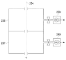
図2は、差動排気部として2つの差動排気機構236、237を用いた例を示す。図2において、差動排気機構236に存在する気体は、ターボ分子ポンプ238により排気され、差動排気機構236の圧力は10-5〜10-1Pa程度に減圧される。また、差動排気機構237に存在する気体は、ターボ分子ポンプ240により排気され、差動排気機構237の圧力は10-3〜1Pa程度に減圧される。これにより、電子線発生部と照射部の圧力を良好に維持することが可能となる。
FIG. 2 shows an example in which two
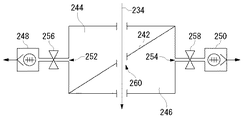
図3は、差動排気部として、電子線234の進行方向に対して斜めに横切る遮蔽板242により、第1のチャンバー244と第2のチャンバー246を形成するように仕切られた差動排気部を用いた例を示す。第1のチャンバー244は、排気口252を備え、排気口252は、バルブ256を介してターボ分子ポンプ248に接続している。第2のチャンバー246は、排気口254を備え、排気口254は、バルブ258を介してターボ分子ポンプ250に接続している。また、遮蔽板242は、電子線234の進路上に、差動排気口260を備えている。第1のチャンバー244の気体は、ターボ分子ポンプ248により排気され、第1のチャンバーの圧力は10-5〜10-1Pa程度に減圧される。また、第2のチャンバー246に存在する気体は、ターボ分子ポンプ250により排気され、第2のチャンバー246の圧力は10-3〜1Pa程度に減圧される。これにより、電子線発生部と照射部の圧力を良好に維持することが可能となる。さらに、図2の2つの差動排気機構を有する場合に比べ、同じ差動排気能力を保持しながら、差動排気部の長さを1/2にすることができることとなる。
FIG. 3 shows a differential exhaust unit that is partitioned so as to form a
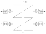
図4は、図3の差動排気部をさらに2つ用いた例を示す。これにより、さらに効率的に差動排気をすることができる。 FIG. 4 shows an example in which two further differential exhaust parts of FIG. 3 are used. Thereby, differential exhaust can be performed more efficiently.
本発明のエネルギー線照射装置に用いるエネルギー線としては、特に制限はないが、例えば、電子線、イオン線、中性粒子線、赤外線、紫外線、原子線、X線、γ線等を挙げることができ、これらを組み合わせて照射してもよい。 The energy beam used in the energy beam irradiation apparatus of the present invention is not particularly limited, and examples thereof include an electron beam, an ion beam, a neutral particle beam, an infrared ray, an ultraviolet ray, an atomic beam, an X-ray, and a γ ray. These may be combined and irradiated.
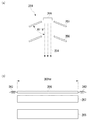
本発明に用いるエネルギー線発生部としては、特に制限はないが、例えば、ピアス型のエネルギー線発生装置を備えるものを挙げることができる。図5に、ピアス型の電子銃の例を示す。なお、図5(a)はピアス型電子銃264の正面図、図5(b)は側面図を示す。図5において、ピアス型電子銃264は、カソード206、ウェネルト207、アノード208を備えている。また、カソード206は、細長いリボン状(矩形)または線状であり、直線状に保つために、その両端に接続したバネ262により引っ張られている。カソード206から放出される電子線234は、ウェネルト207によりその放出量が調整され、アノード208に印加された電圧により加速され、電子線が放出される。このピアス型の電子銃を用いることにより、略線状または略矩形状の平行な電子線を効率よく放出することができることとなる。カソード206の構成材料としては、特に制限はないが、W、Re、Ta、LaB6、ZrO/W、ThO−W(トリエーテッドW)等が用いられる。また、カソード206のサイズは、必要とする電子線の幅や長さ等により適宜決定することができるが、例えば、長さとして10〜1000mm、好ましくは100〜700mm、より好ましくは200〜500mmを、リボン状の場合は、幅として0.01〜10mm、好ましくは0.01〜5mm、より好ましくは0.02〜1mmのものを、厚さとして0.01〜10mm、好ましくは0.1〜5mm、より好ましくは0.1〜1mmのものを、線状の場合は、直径として0.01〜10mm、好ましくは0.1〜5mm、より好ましくは0.2〜1mmのものを挙げることができる。また、カソードの厚さ若しくは直径に対して、長さが200倍以上のものとすることが好ましい。
Although there is no restriction | limiting in particular as an energy beam generation part used for this invention, For example, what is equipped with a pierce-type energy beam generator can be mentioned. FIG. 5 shows an example of a pierce-type electron gun. 5A is a front view of the pierce-
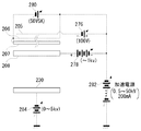
本発明の電子線照射装置201において、図7に示す機構の電気系を備えることにより、照射する電子線量を任意に変化させることができる。図7において、カソード206はカソード電源280に、反射電極205は電源276に、アノード208は電源278に、さらにカソード電源280、電源276および電源278は加速電源282に、それぞれ接続されている。また、ウエハ230は図示しないステージを通じて電源284に接続されている。そして、電源276、278、284、カソード電源280、および加速電源282は、いずれも可変電源であり、これらの電圧を変化させることにより、ウエハ230に照射される電子線量を任意に変化させることが可能となる。例えば、カソード206とアノード208との間の電圧を一定に保ったまま、カソード206の電圧を変化させることにより、電子線量を変化させることができる。また、反射電極205に、カソード206と同電位〜マイナス100Vの電位をかけることもできる。さらに、カソード206に通電する電気量と、ウェネルト207へのバイアス電位を変化させることにより、電子線量を変化させることもできる。照射される電子線エネルギーとしては、被照射体の性質により適宜決定されるが、例えば、100keV以下とすることができる。
In the electron
本発明に用いるエネルギー線発生部の他の例としては、図6に示すような、イオン銃を備えるものを挙げることができる。図6において、イオン銃266は、プラズマ発生部268、アノード272、カソード274を備えており、プラズマ発生部268で発生させたプラズマ270をアノード272で引き出し、カソード274で加速することにより、正イオン線276が放出される。なお、陰イオン線を放出させる場合は、アノード272とカソード274を逆に配置させればよい。このイオン銃を用いることにより、エネルギー線としてイオン線を用いた本発明のイオン線照射装置とすることができる。
As another example of the energy beam generating unit used in the present invention, there can be mentioned one provided with an ion gun as shown in FIG. In FIG. 6, the
本発明の電子線照射装置201を用いてウエハ230に電子線234を照射する場合には、駆動装置290によりステージ232を水平方向に適宜移動させながら、電子線234を照射することもできる。例えば、電子線234の断面形状が略線状または略矩形である場合に、その短軸方向にステージ232を連続的に移動させることにより、ウエハ230に連続的に電子線を照射することができる。また、このときにステージ232の移動速度を変化させることにより、ウエハ230に照射される電子線量を変化させることもできる。
When the electron
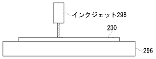
次に、本発明の電子線照射装置を用いて、ウエハへのパタン作成を例にして、パタンを作成する方法について説明する。まず、図8に示すように、ウエハ230をステージ296に載せ、インクジェット298によりウエハ表面にレジスト材を吹き付けて、任意の図形をパタン化処理する。この際、インクジェット298をX−Y方向に高速に移動させるか、または、インクジェット298を固定し、ステージ296をX−Yステージとして用い、ウエハ230をX−Y方向に移動させてもよく、あるいは、インクジェット298およびステージ296の双方を移動させてもよい。また、この場合に複数のインクジェットを用いてもよい。この際の、パタンの線幅としては、特に制限はないが、例えば100μm以下、好ましくは50μm以下、より好ましくは10μm以下のものが挙げられる。また、パタン化処理を行う前に、ウエハを清浄化することが好ましい。
Next, a method of creating a pattern using the electron beam irradiation apparatus of the present invention as an example of pattern creation on a wafer will be described. First, as shown in FIG. 8, a
次に、ウエハ230を電子線照射装置201のステージ232に載せ、電子線234を照射することにより、レジスト材を硬化させ、パタンを作成することができる。この際に、ピアス型電子銃264を用いて、幅の広い電子線234を照射し、駆動機構290によりステージ232を一定速度で移動させることにより、一括してウエハ表面を電子線照射することが可能となる。これにより、効率的にパタンの作成が行えることとなる。
Next, by placing the
なお、ウエハにパタン化処理を行った後、ウエハを80〜150℃に加温し、電子線を照射してもよい。 In addition, after performing the patterning process on the wafer, the wafer may be heated to 80 to 150 ° C. and irradiated with an electron beam.
なお、上記のレジスト材に代えて、低誘電体(low−k)材を用いることもできる。 Note that a low dielectric (low-k) material may be used instead of the resist material.
以上、エネルギー線として電子線を用いた場合を例にして本発明を説明したが、本発明は電子線に限られるものではなく、イオン線、中性粒子線、またはこれらを複数組み合わせて用いること、および、赤外線、紫外線、原子線、X線、γ線等の他のエネルギー線と併用することも本発明に包含される。 As described above, the present invention has been described by taking the case where an electron beam is used as an energy beam as an example. However, the present invention is not limited to an electron beam, and an ion beam, a neutral particle beam, or a combination thereof may be used. , And other energy rays such as infrared rays, ultraviolet rays, atomic rays, X-rays and γ rays are also included in the present invention.
本発明のエネルギー線照射装置またはエネルギー線照射方法、パタン作成方法を用いることにより、半導体を製造することができる。また、従来主として紫外線を用いて行っていた表面処理技術(例えば、レジストのキュア、殺菌・滅菌処理、露光等)において、電子線など、紫外線以外のエネルギー線を用いることが可能となる。そして、電子線等を用いることにより、微細な加工が行えることとなり、表面処理、表面修飾や、ナノテクへの応用が可能となる。 By using the energy beam irradiation apparatus, the energy beam irradiation method, or the pattern creation method of the present invention, a semiconductor can be manufactured. In addition, in a surface treatment technique (for example, resist curing, sterilization / sterilization treatment, exposure, etc.) conventionally performed mainly using ultraviolet rays, it is possible to use energy rays other than ultraviolet rays such as electron beams. By using an electron beam or the like, fine processing can be performed, and surface treatment, surface modification, and application to nanotechnology are possible.
201 電子線照射装置
202 電子線発生部
203 差動排気部
204 照射部
205 反射電極
206 カソード
207 ウェネルト
208 アノード
210、214、260 差動排気口
212、216 遮蔽板
218、222、226、256、258、292 バルブ
220、224、238、240、248、250 ターボ分子ポンプ
228 ドライポンプ
230 ウエハ
232 ステージ
234 電子線
236、237 差動排気機構
242 遮蔽板
244 第1のチャンバー
246 第2のチャンバー
252、254 排気口
262 バネ
264 ピアス型電子銃
266 イオン銃
268 プラズマ発生部
270 プラズマ
272 アノード
274 カソード
276、278、284 電源
280 カソード電源
282 加速電源
290 駆動装置
294 ガス供給部
296 ステージ
298 インクジェット
DESCRIPTION OF
Claims (27)
A differential exhaust device used for energy beam irradiation, wherein the differential exhaust device forms a first chamber and a second chamber by a shielding plate obliquely crossing the traveling direction of the energy beam. A differential exhaust system, wherein the first chamber and the second chamber each have an exhaust port.
Priority Applications (1)
| Application Number | Priority Date | Filing Date | Title |
|---|---|---|---|
| JP2004103051A JP4406311B2 (en) | 2004-03-31 | 2004-03-31 | Energy beam irradiation apparatus and pattern making method using the same |
Applications Claiming Priority (1)
| Application Number | Priority Date | Filing Date | Title |
|---|---|---|---|
| JP2004103051A JP4406311B2 (en) | 2004-03-31 | 2004-03-31 | Energy beam irradiation apparatus and pattern making method using the same |
Publications (3)
| Publication Number | Publication Date |
|---|---|
| JP2005294310A true JP2005294310A (en) | 2005-10-20 |
| JP2005294310A5 JP2005294310A5 (en) | 2007-04-19 |
| JP4406311B2 JP4406311B2 (en) | 2010-01-27 |
Family
ID=35326950
Family Applications (1)
| Application Number | Title | Priority Date | Filing Date |
|---|---|---|---|
| JP2004103051A Expired - Lifetime JP4406311B2 (en) | 2004-03-31 | 2004-03-31 | Energy beam irradiation apparatus and pattern making method using the same |
Country Status (1)
| Country | Link |
|---|---|
| JP (1) | JP4406311B2 (en) |
Cited By (5)
| Publication number | Priority date | Publication date | Assignee | Title |
|---|---|---|---|---|
| JP2008082919A (en) * | 2006-09-28 | 2008-04-10 | Japan Ae Power Systems Corp | Electron beam irradiation device |
| JP2013544031A (en) * | 2010-11-13 | 2013-12-09 | マッパー・リソグラフィー・アイピー・ビー.ブイ. | Charged particle lithography system with intermediate chamber |
| KR20150010994A (en) * | 2012-05-14 | 2015-01-29 | 마퍼 리쏘그라피 아이피 비.브이. | Charged particle lithography system and beam generator |
| US11094426B2 (en) | 2012-05-14 | 2021-08-17 | Asml Netherlands B.V. | Vacuum chamber arrangement for charged particle beam generator |
| US11348756B2 (en) | 2012-05-14 | 2022-05-31 | Asml Netherlands B.V. | Aberration correction in charged particle system |
-
2004
- 2004-03-31 JP JP2004103051A patent/JP4406311B2/en not_active Expired - Lifetime
Cited By (12)
| Publication number | Priority date | Publication date | Assignee | Title |
|---|---|---|---|---|
| JP2008082919A (en) * | 2006-09-28 | 2008-04-10 | Japan Ae Power Systems Corp | Electron beam irradiation device |
| JP2013544031A (en) * | 2010-11-13 | 2013-12-09 | マッパー・リソグラフィー・アイピー・ビー.ブイ. | Charged particle lithography system with intermediate chamber |
| KR20150010994A (en) * | 2012-05-14 | 2015-01-29 | 마퍼 리쏘그라피 아이피 비.브이. | Charged particle lithography system and beam generator |
| JP2015517735A (en) * | 2012-05-14 | 2015-06-22 | マッパー・リソグラフィー・アイピー・ビー.ブイ. | Charged particle lithography system and beam generator |
| US9653261B2 (en) | 2012-05-14 | 2017-05-16 | Mapper Lithography Ip B.V. | Charged particle lithography system and beam generator |
| US10037864B2 (en) | 2012-05-14 | 2018-07-31 | Mapper Lithography Ip B.V. | High voltage shielding and cooling in a charged particle beam generator |
| KR101961914B1 (en) | 2012-05-14 | 2019-03-25 | 마퍼 리쏘그라피 아이피 비.브이. | Charged particle lithography system and beam generator |
| US11094426B2 (en) | 2012-05-14 | 2021-08-17 | Asml Netherlands B.V. | Vacuum chamber arrangement for charged particle beam generator |
| US11348756B2 (en) | 2012-05-14 | 2022-05-31 | Asml Netherlands B.V. | Aberration correction in charged particle system |
| US11705252B2 (en) | 2012-05-14 | 2023-07-18 | Asml Netherlands B.V. | Vacuum chamber arrangement for charged particle beam generator |
| US11961627B2 (en) | 2012-05-14 | 2024-04-16 | Asml Netherlands B.V. | Vacuum chamber arrangement for charged particle beam generator |
| US12387903B2 (en) | 2012-05-14 | 2025-08-12 | Asml Netherlands B.V. | Aberration correction in charged particle system |
Also Published As
| Publication number | Publication date |
|---|---|
| JP4406311B2 (en) | 2010-01-27 |
Similar Documents
| Publication | Publication Date | Title |
|---|---|---|
| US6924493B1 (en) | Ion beam lithography system | |
| US10840054B2 (en) | Charged-particle source and method for cleaning a charged-particle source using back-sputtering | |
| JP6220749B2 (en) | Ion gun, ion milling apparatus, and ion milling method | |
| TWI572997B (en) | Extreme ultraviolet radiation device and radiation generation method | |
| JP2008508684A5 (en) | ||
| JP5709546B2 (en) | Energy beam drawing apparatus and device manufacturing method | |
| EP3518268B1 (en) | Charged-particle source and method for cleaning a charged-particle source using back-sputtering | |
| JP4406311B2 (en) | Energy beam irradiation apparatus and pattern making method using the same | |
| JP6779847B2 (en) | Charged particle device, charged particle drawing device and charged particle beam control method | |
| JP2003036805A (en) | Micro x-ray source | |
| JP2005127800A (en) | Electron beam irradiation apparatus, irradiation method, and electron beam drawing apparatus | |
| US12020893B2 (en) | Ion milling device | |
| CN102939567A (en) | optical system | |
| JP5105729B2 (en) | Processing method with gas cluster ion beam | |
| JP4696478B2 (en) | Plasma X-ray generator | |
| JP2004347510A (en) | Electron beam irradiation device, electron beam irradiation method, and electron beam irradiation object | |
| JPH0254851A (en) | Control method of electric field ionization type gas ion source | |
| JPH01265443A (en) | X-ray aligner | |
| JP2007035642A (en) | Electric field emitter arrangement and method for cleaning emission surface of electric field emitter | |
| CN121355162B (en) | A surface shaping method using a combination of electron and ion beams | |
| JP2964284B2 (en) | Field emission type electron gun stabilization method and field emission type electron gun | |
| KR101998774B1 (en) | Line Type Electron Beam Emission Device | |
| CN103298232A (en) | Ion source | |
| JP4747557B2 (en) | Electron beam irradiation apparatus and ion generator | |
| JP3105931B2 (en) | Electron beam irradiation apparatus and electron beam irradiation method |
Legal Events
| Date | Code | Title | Description |
|---|---|---|---|
| A521 | Request for written amendment filed |
Free format text: JAPANESE INTERMEDIATE CODE: A523 Effective date: 20070228 |
|
| A621 | Written request for application examination |
Free format text: JAPANESE INTERMEDIATE CODE: A621 Effective date: 20070228 |
|
| A131 | Notification of reasons for refusal |
Free format text: JAPANESE INTERMEDIATE CODE: A131 Effective date: 20090623 |
|
| A521 | Request for written amendment filed |
Free format text: JAPANESE INTERMEDIATE CODE: A523 Effective date: 20090810 |
|
| TRDD | Decision of grant or rejection written | ||
| A01 | Written decision to grant a patent or to grant a registration (utility model) |
Free format text: JAPANESE INTERMEDIATE CODE: A01 Effective date: 20091027 |
|
| A01 | Written decision to grant a patent or to grant a registration (utility model) |
Free format text: JAPANESE INTERMEDIATE CODE: A01 |
|
| A61 | First payment of annual fees (during grant procedure) |
Free format text: JAPANESE INTERMEDIATE CODE: A61 Effective date: 20091106 |
|
| FPAY | Renewal fee payment (event date is renewal date of database) |
Free format text: PAYMENT UNTIL: 20121113 Year of fee payment: 3 |
|
| R150 | Certificate of patent or registration of utility model |
Ref document number: 4406311 Country of ref document: JP Free format text: JAPANESE INTERMEDIATE CODE: R150 Free format text: JAPANESE INTERMEDIATE CODE: R150 |
|
| FPAY | Renewal fee payment (event date is renewal date of database) |
Free format text: PAYMENT UNTIL: 20121113 Year of fee payment: 3 |
|
| FPAY | Renewal fee payment (event date is renewal date of database) |
Free format text: PAYMENT UNTIL: 20131113 Year of fee payment: 4 |
|
| R250 | Receipt of annual fees |
Free format text: JAPANESE INTERMEDIATE CODE: R250 |
|
| R250 | Receipt of annual fees |
Free format text: JAPANESE INTERMEDIATE CODE: R250 |
|
| R250 | Receipt of annual fees |
Free format text: JAPANESE INTERMEDIATE CODE: R250 |
|
| R250 | Receipt of annual fees |
Free format text: JAPANESE INTERMEDIATE CODE: R250 |
|
| R250 | Receipt of annual fees |
Free format text: JAPANESE INTERMEDIATE CODE: R250 |
|
| R250 | Receipt of annual fees |
Free format text: JAPANESE INTERMEDIATE CODE: R250 |
|
| R250 | Receipt of annual fees |
Free format text: JAPANESE INTERMEDIATE CODE: R250 |
|
| R250 | Receipt of annual fees |
Free format text: JAPANESE INTERMEDIATE CODE: R250 |
|
| R250 | Receipt of annual fees |
Free format text: JAPANESE INTERMEDIATE CODE: R250 |
|
| R250 | Receipt of annual fees |
Free format text: JAPANESE INTERMEDIATE CODE: R250 |
|
| R250 | Receipt of annual fees |
Free format text: JAPANESE INTERMEDIATE CODE: R250 |
|
| R250 | Receipt of annual fees |
Free format text: JAPANESE INTERMEDIATE CODE: R250 |
|
| EXPY | Cancellation because of completion of term |