JP2005294098A - Manufacturing method of fuel cell - Google Patents
Manufacturing method of fuel cell Download PDFInfo
- Publication number
- JP2005294098A JP2005294098A JP2004108873A JP2004108873A JP2005294098A JP 2005294098 A JP2005294098 A JP 2005294098A JP 2004108873 A JP2004108873 A JP 2004108873A JP 2004108873 A JP2004108873 A JP 2004108873A JP 2005294098 A JP2005294098 A JP 2005294098A
- Authority
- JP
- Japan
- Prior art keywords
- molded body
- fuel cell
- adhesive
- separators
- liquid adhesive
- Prior art date
- Legal status (The legal status is an assumption and is not a legal conclusion. Google has not performed a legal analysis and makes no representation as to the accuracy of the status listed.)
- Granted
Links
Images
Classifications
-
- Y—GENERAL TAGGING OF NEW TECHNOLOGICAL DEVELOPMENTS; GENERAL TAGGING OF CROSS-SECTIONAL TECHNOLOGIES SPANNING OVER SEVERAL SECTIONS OF THE IPC; TECHNICAL SUBJECTS COVERED BY FORMER USPC CROSS-REFERENCE ART COLLECTIONS [XRACs] AND DIGESTS
- Y02—TECHNOLOGIES OR APPLICATIONS FOR MITIGATION OR ADAPTATION AGAINST CLIMATE CHANGE
- Y02E—REDUCTION OF GREENHOUSE GAS [GHG] EMISSIONS, RELATED TO ENERGY GENERATION, TRANSMISSION OR DISTRIBUTION
- Y02E60/00—Enabling technologies; Technologies with a potential or indirect contribution to GHG emissions mitigation
- Y02E60/30—Hydrogen technology
- Y02E60/50—Fuel cells
-
- Y—GENERAL TAGGING OF NEW TECHNOLOGICAL DEVELOPMENTS; GENERAL TAGGING OF CROSS-SECTIONAL TECHNOLOGIES SPANNING OVER SEVERAL SECTIONS OF THE IPC; TECHNICAL SUBJECTS COVERED BY FORMER USPC CROSS-REFERENCE ART COLLECTIONS [XRACs] AND DIGESTS
- Y02—TECHNOLOGIES OR APPLICATIONS FOR MITIGATION OR ADAPTATION AGAINST CLIMATE CHANGE
- Y02P—CLIMATE CHANGE MITIGATION TECHNOLOGIES IN THE PRODUCTION OR PROCESSING OF GOODS
- Y02P70/00—Climate change mitigation technologies in the production process for final industrial or consumer products
- Y02P70/50—Manufacturing or production processes characterised by the final manufactured product
Landscapes
- Fuel Cell (AREA)
Abstract
【課題】 セパレータの外周部間の接着剤の硬化時間を短くして生産性をあげることができ、しかも接着剤層切れなどによる接着不良、シール不良を生じない燃料電池の製造方法の提供。
【解決手段】 2枚のセパレータ18の外周部の対向面に液状接着剤33aを塗布する第1工程と、該2枚のセパレータ間にMEAの電解質膜11の周縁部を挟む第2工程と、液状接着剤33aを硬化させて単セル19を製造する第3工程と、を有する燃料電池の製造方法であって、
第2工程で、予め成形され硬化された成形体33bを2枚のセパレータの外周部間に挿入し、ほぼ該成形体の厚み分、第1工程でセパレータに塗布する液状接着剤33aの塗布厚さを薄くし、該液状接着剤33aの塗布厚さを薄くした分、第3工程での接着剤33a硬化時間を短くする、燃料電池の製造方法。
【選択図】 図2PROBLEM TO BE SOLVED: To provide a method for manufacturing a fuel cell, which can shorten the curing time of an adhesive between the outer peripheral portions of a separator and increase the productivity, and does not cause poor adhesion and poor sealing due to an adhesive layer breakage.
A first step of applying a liquid adhesive 33a to the opposing surfaces of the outer peripheral portions of two separators 18, and a second step of sandwiching a peripheral portion of an electrolyte membrane 11 of MEA between the two separators; A third step of manufacturing the single cell 19 by curing the liquid adhesive 33a, and a method of manufacturing a fuel cell,
In the second step, the molded body 33b molded and hardened in advance is inserted between the outer peripheral portions of the two separators, and the coating thickness of the liquid adhesive 33a applied to the separator in the first step is approximately the thickness of the molded body. A method of manufacturing a fuel cell in which the curing time of the adhesive 33a in the third step is shortened by the thickness of the liquid adhesive 33a.
[Selection] Figure 2
Description
本発明は燃料電池の製造方法に関し、とくにセパレータ間接着剤の硬化時間を短縮させる燃料電池の製造方法に関する。 The present invention relates to a method for manufacturing a fuel cell, and more particularly to a method for manufacturing a fuel cell that shortens the curing time of an adhesive between separators.
燃料電池(単セル)は、電解質膜の一面にアノードを設け、他面にカソードを設けた膜−電極アッセンブリ(MEA)をセパレータで挟んだものから構成される。アノードには燃料ガス(水素含有ガス)が供給され、カソードには酸化剤ガス(酸素含有ガス、通常、エア)が供給される。電解質膜を挟む2枚のセパレータの外周部間は接着剤によりシール接着される。 A fuel cell (single cell) is configured by sandwiching a membrane-electrode assembly (MEA) having an anode on one surface and a cathode on the other surface between separators. A fuel gas (hydrogen-containing gas) is supplied to the anode, and an oxidant gas (oxygen-containing gas, usually air) is supplied to the cathode. The outer peripheral portions of the two separators sandwiching the electrolyte membrane are sealed with an adhesive.
単セルは、通常、2枚のセパレータの外周部の対向面に液状接着剤を塗布し、該2枚のセパレータ間にMEAの電解質膜の周縁部を挟み、液状接着剤を硬化させて、製造される。しかし、液状接着剤の硬化に時間がかかり(約1.5mmの接着剤層を熱と圧力をかけて硬化させるのに約1時間弱かかる)、生産性が悪い。液状接着剤の硬化時間を短縮するために液状接着剤の塗布厚さを薄くすると、接着剤層を挟んで対向するセパレータに電気的短絡が生じてしまって単セルが成立しなくなる。 A single cell is usually manufactured by applying a liquid adhesive to the opposing surfaces of the outer periphery of two separators, sandwiching the peripheral edge of the MEA electrolyte membrane between the two separators, and curing the liquid adhesive. Is done. However, it takes time to cure the liquid adhesive (it takes about 1 hour to cure the adhesive layer of about 1.5 mm by applying heat and pressure), and the productivity is poor. If the coating thickness of the liquid adhesive is reduced in order to shorten the curing time of the liquid adhesive, an electrical short circuit occurs in the separators facing each other with the adhesive layer interposed therebetween, and a single cell cannot be established.
特開平7−65847号公報は、電解質膜を両面側から樹脂の補強枠で挟み、その両面側に、カーボンセパレータとの間にシール体を配置した、補強シール構造を開示している。補強枠を設けた構造では、シーラントが極薄となってシーラント硬化時間は短いが、反面、以下の問題を伴う。
補強枠と膜との間、補強枠とセパレータの間、補強枠とシール体との間、等にあるシーラントの層の厚さが極薄となり、あるいは補強枠の面のうねりや凹凸をシーラントの層で吸収しきれずシーラント層切れが生じ、その結果、接着不良、リーク(シール不良)が生じるおそれがある。また、補強枠とシール体とシーラントは種類の異なる樹脂材からなるので、接着性が常に良好であるとは限らない。
The thickness of the sealant layer between the reinforcing frame and the membrane, between the reinforcing frame and the separator, between the reinforcing frame and the seal body, etc. becomes extremely thin, or the undulations and irregularities on the surface of the reinforcing frame are removed. The layers cannot be absorbed and the sealant layer is cut, and as a result, there is a risk of poor adhesion and leakage (seal failure). Further, since the reinforcing frame, the sealing body, and the sealant are made of different types of resin materials, the adhesiveness is not always good.
本発明が解決しようとする課題は、通常の単セルの製造方法における、液状接着剤の硬化に時間がかかり、生産性が悪いという問題であり、特開平7−65847号公報のように膜を補強枠で挟むシール構造では、接着不良やシール不良が生じるおそれがあるという問題である。 The problem to be solved by the present invention is the problem that it takes time to cure the liquid adhesive in the ordinary single cell production method, and the productivity is poor, and a film is formed as disclosed in JP-A-7-65847. In the seal structure sandwiched between the reinforcing frames, there is a problem that adhesion failure or seal failure may occur.
本発明の目的は、単セルの電解質膜を挟むセパレータの外周部間の接着剤の硬化時間を(上記の通常の燃料電池製造方法の接着剤硬化時間より)短くして生産性をあげることができ、しかも接着剤層切れなどによる接着不良、シール不良を生じない燃料電池の製造方法を提供することにある。 The object of the present invention is to increase the productivity by shortening the curing time of the adhesive between the outer peripheral portions of the separator sandwiching the electrolyte membrane of the single cell (than the adhesive curing time of the above-mentioned ordinary fuel cell manufacturing method). Another object of the present invention is to provide a method of manufacturing a fuel cell that does not cause adhesion failure or sealing failure due to cutting of the adhesive layer.
上記課題を解決し、上記目的を達成する本発明はつぎの通りである。
(1) 2枚のセパレータの外周部の対向面に液状接着剤を塗布し、セパレータの外周部の対向面間に電解質膜の周縁部と予め成形され硬化された成形体を挟み、液状接着剤を硬化させて2枚のセパレータを接着する燃料電池の製造方法。
(2) 2枚のセパレータの外周部の対向面に液状接着剤を塗布する第1工程と、
該2枚のセパレータ間にMEAの電解質膜の周縁部を挟む第2工程と、
前記液状接着剤を硬化させて単セルを製造する第3工程と、
を有する燃料電池の製造方法であって、
前記第2工程で予め成形され硬化された成形体を前記2枚のセパレータの外周部間に挿入し、ほぼ該成形体の厚み分、前記第1工程でセパレータに塗布する液状接着剤の塗布厚さを薄くし、該液状接着剤の塗布厚さを薄くした分、前記第3工程での接着剤硬化時間を短くする、(1)記載の燃料電池の製造方法。
(3) 前記成形体と前記2枚のセパレータの何れのセパレータの外周部との間にも前記接着剤が存在する(1)または(2)記載の燃料電池の製造方法。
(4) 前記成形体を、前記2枚のセパレータの外周部間に1層だけ挿入する(1)または(2)記載の燃料電池の製造方法。
(5) 前記成形体の材料と、前記液状接着剤の材料とは、同じ種類の材料である(1)または(2)記載の燃料電池の製造方法。
(6) 前記成形体は厚み方向に弾性を有する(1)または(2)記載の燃料電池の製造方法。
(7) 前記セパレータはカーボンセパレータである(1)または(2)記載の燃料電池の製造方法。
The present invention for solving the above problems and achieving the above object is as follows.
(1) A liquid adhesive is applied to the opposing surfaces of the outer peripheral portions of the two separators, and the peripheral portion of the electrolyte membrane and a pre-molded and cured molded body are sandwiched between the opposing surfaces of the outer peripheral portions of the separator. A method for manufacturing a fuel cell, in which two separators are bonded by curing.
(2) a first step of applying a liquid adhesive to the opposing surfaces of the outer peripheral portions of the two separators;
A second step of sandwiching the periphery of the MEA electrolyte membrane between the two separators;
A third step of producing a single cell by curing the liquid adhesive;
A fuel cell manufacturing method comprising:
Insert the molded body pre-molded and cured in the second step between the outer peripheral portions of the two separators, and apply the liquid adhesive to the separator in the first step, approximately the thickness of the molded body The method for producing a fuel cell according to (1), wherein the adhesive curing time in the third step is shortened by the thickness of the liquid adhesive and the coating thickness of the liquid adhesive being reduced.
(3) The method for producing a fuel cell according to (1) or (2), wherein the adhesive is present between the molded body and an outer peripheral portion of any one of the two separators.
(4) The method for producing a fuel cell according to (1) or (2), wherein only one layer of the molded body is inserted between the outer peripheral portions of the two separators.
(5) The method for producing a fuel cell according to (1) or (2), wherein the material of the molded body and the material of the liquid adhesive are the same type of material.
(6) The method for producing a fuel cell according to (1) or (2), wherein the molded body has elasticity in a thickness direction.
(7) The method for producing a fuel cell according to (1) or (2), wherein the separator is a carbon separator.
上記(1)または(2)の燃料電池の製造方法によれば、予め成形され硬化された成形体を挟むので、液状接着剤の層を薄くすることができ液状接着剤の硬化時間を短縮し生産性を上げることができる。また、2枚のセパレータの外周部の対向面に液状接着剤を塗布した後成形体および膜を挟むので、セパレータが、直接、成形体や膜に接触して接着剤の層切れが生じるおそれはなく、接着剤層の厚みも成形体の厚みを適当に選定することによって必要厚さを確保できるので、接着不良やシール不良は生じない。
上記(3)の燃料電池の製造方法によれば、成形体と前記2枚のセパレータの何れのセパレータの外周部との間にも接着剤が存在させるので、セパレータが、直接、成形体に接触して接着剤の層切れと、それによる接着不良やシール不良が生じることはない。
上記(4)の燃料電池の製造方法によれば、成形体を、2枚のセパレータの外周部間に1層だけ挿入するので、2層以上挿入した場合の、成形体間の接着剤塗布が必要でなく、成形体挿入による接着剤塗布時間や塗布作業の増加はない。従来の補強枠挿入シール方法では、複数の補強枠を挿入するので、接着剤塗布時間や塗布作業の増加する。
上記(5)の燃料電池の製造方法によれば、成形体の材料と、液状接着剤の材料とを、同じ種類の材料としておけば、接着剤層と成形体との接着性、シール性は、単一接着剤層の場合と同じ程度に高くなり、成形体挿入による接着性、シール性の低下はない。従来の補強枠挿入シール方法では、補強枠とシール体とシーラントが別種類の材料となっているため、接着性、シール性が単一種類のシール構造に比べて低下しやすい。
上記(6)の燃料電池の製造方法によれば、成形体は厚み方向に弾性を有するので、液状接着剤には硬化後の弾性をもたす必要がなく、接着剤選定の自由度が増大する。
上記(7)の燃料電池の製造方法によれば、本発明を単セルの2枚のカーボンセパレータ間のシール接着に適用することにより、カーボンセパレータをもつ単セルの生産性を上げることができる。メタルセパレータと樹脂フレームの組み合わせ構造では、樹脂フレームの膜側にも接着剤を塗布する必要があり、本発明の生産性向上のメリットはカーボンセパレータの場合ほどにが得られない。
According to the fuel cell manufacturing method of the above (1) or (2), since the molded body that has been molded and cured in advance is sandwiched, the liquid adhesive layer can be made thin and the curing time of the liquid adhesive can be shortened. Productivity can be increased. In addition, since the molded product and the film are sandwiched after the liquid adhesive is applied to the opposing surfaces of the outer peripheral portions of the two separators, there is a possibility that the separator may come into direct contact with the molded product or the film and the adhesive may be broken. In addition, since the necessary thickness can be secured by appropriately selecting the thickness of the molded body, the adhesive layer and the seal are not defective.
According to the fuel cell manufacturing method of (3) above, since the adhesive is present between the molded body and the outer peripheral portion of any one of the two separators, the separator directly contacts the molded body. As a result, the adhesive layer is not cut off, and adhesion failure and seal failure do not occur.
According to the fuel cell manufacturing method of (4) above, only one layer of the molded body is inserted between the outer peripheral portions of the two separators. Therefore, when two or more layers are inserted, the adhesive is applied between the molded bodies. It is not necessary, and there is no increase in adhesive application time and application work due to insertion of the molded body. In the conventional reinforcing frame insertion sealing method, since a plurality of reinforcing frames are inserted, the adhesive application time and application work increase.
According to the method for producing a fuel cell of (5) above, if the material of the molded body and the material of the liquid adhesive are the same type of material, the adhesiveness between the adhesive layer and the molded body and the sealing performance are as follows. , It becomes as high as in the case of a single adhesive layer, and there is no decrease in adhesion and sealing properties due to insertion of the molded body. In the conventional reinforcing frame insertion sealing method, since the reinforcing frame, the seal body, and the sealant are made of different types of materials, the adhesiveness and the sealing performance are likely to be lower than those of a single type of sealing structure.
According to the fuel cell manufacturing method of (6) above, since the molded body has elasticity in the thickness direction, the liquid adhesive does not need to have elasticity after curing, and the degree of freedom in selecting the adhesive increases. To do.
According to the fuel cell manufacturing method of the above (7), the productivity of a single cell having a carbon separator can be increased by applying the present invention to sealing adhesion between two carbon separators of a single cell. In the combined structure of the metal separator and the resin frame, it is necessary to apply an adhesive also to the film side of the resin frame, and the merit of improving the productivity of the present invention cannot be obtained as much as in the case of the carbon separator.
以下に、本発明の燃料電池の製造方法を、図1〜図4を参照して説明する。
本発明の燃料電池の製造方法が適用される燃料電池は、低温型燃料電池であり、たとえば、固体高分子電解質型燃料電池1である。該燃料電池1は、たとえば燃料電池自動車に搭載される。ただし、自動車以外に用いられてもよい。
Below, the manufacturing method of the fuel cell of this invention is demonstrated with reference to FIGS.
The fuel cell to which the fuel cell manufacturing method of the present invention is applied is a low-temperature fuel cell, for example, a solid polymer electrolyte fuel cell 1. The fuel cell 1 is mounted on, for example, a fuel cell vehicle. However, it may be used other than an automobile.
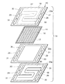
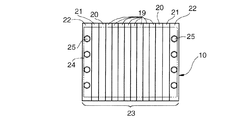
固体高分子電解質型燃料電池10は、図1〜図4に示すように、膜−電極アッセンブリ(MEA:Membrane-Electrode Assembly )とセパレータ18との積層体からなる。積層方向は上下方向に限るものではなく、任意の方向でよい。
膜−電極アッセンブリは、イオン交換膜からなる電解質膜11とこの電解質膜の一面に配置された触媒層からなる電極(アノード、燃料極)14および電解質膜の他面に配置された触媒層からなる電極(カソード、空気極)17とからなる。膜−電極アッセンブリとセパレータ18との間には、アノード側、カソード側にそれぞれ拡散層13、16が設けられる。
As shown in FIGS. 1 to 4, the solid polymer
The membrane-electrode assembly includes an
セパレータ18には、アノード14、カソード17に燃料ガス(水素)および酸化ガス(酸素、通常は空気)を供給するための反応ガス流路27、28(燃料ガス流路27、酸化ガス流路28)と、その裏面に冷媒(通常、冷却水)を流すための冷媒流路26が形成されている。セパレータ18には、燃料ガス流路27に燃料ガスを供給、排出するための燃料ガスマニホールド30、酸化ガス流路28に酸化ガスを供給、排出するための酸化ガスマニホールド31、冷媒流路26に冷媒を供給、排出するための冷媒マニホールド29が形成されている。流体流路26、27、28、29、30、31をシールするために、ゴムガスケット32や接着剤シール33が設けられている。単セル19の、膜11を挟む2枚のセパレータ18同志は、セパレータ18の外周部の対向面間にある接着剤シール33によってシール接着され、かつ、絶縁されている。隣接するモジュール同志は電気的に導通され、かつ、セパレータ間がガスケット32によってシールされている。
セパレータ18は、望ましくは、カーボンセパレータである。ただし、セパレータ18は、メタルセパレータであってもよいし、導電性樹脂セパレータであってもよいし、メタルセパレータと樹脂フレームの組合せであってもよいし、あるいは、これらのセパレータの組合せであってもよい。
In the
The
膜−電極アッセンブリとセパレータ18を重ねて単位燃料電池(「単セル」ともいう)19を構成し、少なくとも1つのセル(たとえば、1〜3個のセルから1モジュールを構成する)からモジュールを構成し、モジュールを積層してセル積層体とし、セル積層体のセル積層方向両端に、ターミナル20、インシュレータ21、エンドプレート22を配置し、セル積層体をセル積層方向に締め付け、セル積層体の外側でセル積層方向に延びる締結部材(たとえば、テンションプレート24)、ボルト・ナット25により固定して、燃料電池スタック23を構成する。
A unit fuel cell (also referred to as “single cell”) 19 is configured by stacking the membrane-electrode assembly and the
各セル19の、アノード側14では、水素を水素イオン(プロトン)と電子にする反応が行われ、水素イオンは電解質膜11中をカソード側に移動し、カソード17側では酸素と水素イオンおよび電子(隣りのMEAのアノードで生成した電子がセパレータを通してくる、またはセル積層方向一端のセルのアノードで生成した電子が外部回路を通して他端のセルのカソードにくる)から水を生成する反応が行われ、かくして発電が行われる。
アノード側:H2 →2H+ +2e-
カソード側:2H+ +2e- +(1/2)O2 →H2 O
The reaction of converting hydrogen into hydrogen ions (protons) and electrons is performed on the
Anode side: H 2 → 2H + + 2e −
Cathode side: 2H + + 2e − + (1/2) O 2 → H 2 O
本発明の単セル19の製造方法は、2枚のセパレータ18の外周部(セパレータの周縁部と各マニホールド29、30、31のまわり)の対向面に液状接着剤33aを塗布し、セパレータの外周部の対向面間にMEAの電解質膜11の周縁部と予め成形され硬化された成形体33bを挟み、液状接着剤33aを硬化させて2枚のセパレータ18を接着する方法である。
The manufacturing method of the
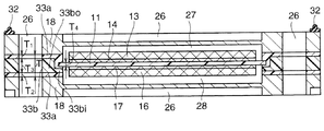
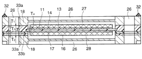
さらに詳しくは、本発明の単セル19の製造方法は、単セル19の2枚のセパレータ18の外周部(セパレータの周縁部と各マニホールド29、30、31のまわり)の対向面に液状接着剤33aを塗布する第1工程と、該2枚のセパレータ18間にMEAの電解質膜11の周縁部を挟む第2工程と、液状接着剤33aを硬化させて単セル19を製造する第3工程と、を有する燃料電池19の製造方法であって、第2工程で、予め成形され硬化された成形体33bを2枚のセパレータ18の外周部間に挿入する方法である。この方法では、ほぼ成形体33bの厚み分、第1工程でセパレータに塗布する液状接着剤33aの塗布厚さを薄くし(第1のセパレータ18に塗布した液状接着剤33aの硬化後の厚さT1と、第2のセパレータ18に塗布した液状接着剤33aの硬化後の厚さT2と、成形体33bの厚みT3との和が、成形体33bを挿入しない通常のセルのセパレータ間の接着剤層33の厚さTとほぼ等しくなるようにする)、液状接着剤の塗布厚さを薄くした分(TをT1、T2と薄くした分)、第3工程での接着剤硬化時間(熱と圧力をかけて接着剤を硬化する時間)を短くする。T1、T2は、約0.02mm以上確保する。膜11の厚みT4は40〜60μmである。
More specifically, the manufacturing method of the
たとえば、Tが約0.15mm、T3が約0.1mm、T1、T2が0.025mmである場合には、成形体を挿入しない場合の、0.15mm厚さの液状接着剤を硬化する時間(約1時間弱)が、成形体を挿入する場合は、0.025mm厚さの液状接着剤を硬化する時間に大幅に短くなる。 For example, when T is about 0.15 mm, T3 is about 0.1 mm, and T1 and T2 are 0.025 mm, the time for curing the liquid adhesive having a thickness of 0.15 mm when the molded body is not inserted. However, when the molded body is inserted, the time for curing the liquid adhesive having a thickness of 0.025 mm is significantly shortened.
予め成形され硬化された成形体33bを2枚のセパレータ18の外周部間に挿入する場合、図2に示すように、成形体33bの電解質膜11の周縁部と重なる部分33biはその他の成形体部分33boより、厚さを薄くしてもよいし、あるいは、図4に示すように、成形体33bの厚さを、成形体全域において一定で薄くしてもよい。
When the molded
第2、第3工程において、成形体33bと2枚のセパレータ18の何れのセパレータ18の外周部との間にも、接着剤33aが存在する。したがって、成形体33bが直接、セパレータ18に接触することはない。
In the second and third steps, the adhesive 33a exists between the molded
第2工程において、成形体33bを、膜11を挟んで対向する2枚のセパレータ18の外周部間に1層だけ挿入する。成形体33bを複数層挿入することはしない。成形体33bを複数層挿入すると成形体33間のシールのために成形体33同士の対向面に接着剤を塗布しなければならなくなるので、作業が複雑かつ長時間になるから、それを避けるためである。
In the second step, only one layer of the molded
望ましくは、成形体33bの材料と、液状接着剤33aの材料とは、同じ種類の材料である。ただし、成形体33bの材料と、液状接着剤33aの材料とを互いに異ならせてもよい。
成形体33bの材料と、液状接着剤33aの材料とが、同じ種類の材料である場合は、単セル製造後、すなわち、液状接着剤33a硬化後は、成形体33bの部分と硬化液状接着剤33aの部分とは、一体不可分となり、区別がなくなり、製品としては、通常の、接着剤全厚が液状接着剤33aの硬化したものからなるセルと変わりがなくなる。
Desirably, the material of the molded
When the material of the molded
成形体33bは厚み方向(セルの厚み方向と同じ方向)に、弾性を有するような材料にて形成されている。その理由は、燃料電池スタックとした時には、スタック締めつけ荷重が各セル19にかかり、接着剤にもかかる。膜11が厚さが薄くなる方向にクリープすると接着剤33も弾性変形して厚さが薄くなって、電極と拡散層とセパレータの各接触抵抗を小に維持するためである。成形体33bに弾性をもたせておけば、液状接着剤33aは必ずしも弾性をもつ必要がなく、硬化後は硬質となってもよく、自由な材料選定ができ、液状接着剤33aの材料選択の自由度が上がる。
The molded
望ましくは、セパレータ18はカーボンセパレータである。メタルセパレータの場合は、通常、樹脂フレームと組み合わせて使用されるが、樹脂フレームは硬質であって、本発明の成形体33bにはなり得ない。また、樹脂フレームの両面に接着剤を塗布しなければならず、接着剤塗布工数が増えて、本発明のメリットが少なくなる。
Desirably, the
つぎに、本発明の燃料電池の製造方法の作用・効果を説明する。
本発明の燃料電池の製造方法では、セパレータ18の外周部の対向面間に、予め成形され硬化された成形体33bを挟むので、セパレータ18の外周部に塗布する液状接着剤33aの層を(成形体33bを挟まず接着剤全厚を液状接着剤33aとする場合に比べて)薄くすることができ、液状接着剤33aの硬化時間を(接着剤全厚が液状接着剤33aとする場合に比べて)短縮でき、生産性を上げることができる。
Next, the operation and effect of the fuel cell manufacturing method of the present invention will be described.
In the fuel cell manufacturing method of the present invention, the molded
また、単セル19の膜11を挟む2枚のセパレータ18の外周部の対向面に液状接着剤33aを塗布した後、液状接着剤33aを塗布したセパレータ面で成形体33aおよび膜11を挟むので、セパレータ18が、直接、成形体33bや膜11に接触して液状接着剤33aの層切れを起こすおそれはない。また、液状接着剤33aの硬化後の成形体33bと接着剤層33aの和の厚さは、成形体33bの厚みを適当に選定することによって必要厚さ(約0.15mm以上は確保したい)を確保できるので、接着不良やシール不良は生じない。
In addition, since the
また、成形体33bを、2枚のセパレータ18の外周部間に1層だけ挿入するので、2層以上挿入した場合に必要となる、成形体33b間の接着剤塗布が必要でなく、成形体33b挿入による接着剤塗布時間や塗布作業の増加はない。すなわち、セパレータ18の対向面に液状接着剤33aを塗布するだけでよく、成形体33bの方には液状接着剤33aを塗布する必要はない。
Further, since only one layer of the molded
また、成形体33bの材料と、液状接着剤33aの材料とを、同じ種類の材料としておけば、接着剤層33aと成形体33bとの接着性、シール性は、通常の単セル製造の単一接着剤層の場合と同じ程度に高くなり、成形体33b挿入による接着性、シール性の低下はない。
また、成形体33bは厚み方向に弾性を有するので、液状接着剤33aには硬化後の弾性をもたす必要がなく、液状接着剤33aの材料選定の自由度が増大する。
In addition, if the material of the molded
Further, since the molded
10 (固体高分子電解質型)燃料電池
11 電解質膜
13 拡散層
14 電極(アノード、燃料極)
16 拡散層
17 電極(カソード、空気極)
18 セパレータ
19 セル
20 ターミナル
21 インシュレータ
22 エンドプレート
23 スタック
24 外側部材または締結部材(テンションプレート)
25 ボルト
26 冷媒流路
27 燃料ガス流路
28 酸化ガス流路
29 冷媒マニホールド
30 燃料ガスマニホールド
31 酸化ガスマニホールド
32 ガスケット
33 接着剤シール
33a 液状ガスケット(硬化前または硬化後)
33b 成形体
33bi 成形体33bの、電解質膜11の周縁部と重なる部分
33bo 成形体33bの、33bi以外の部分
T 成形体33bを挿入しない通常のセルのセパレータ間の接着剤層33の厚さ
T1 第1のセパレータ18に塗布した液状接着剤33aの硬化後の厚さ
T2 第2のセパレータ18に塗布した液状接着剤33aの硬化後の厚さ
T3 成形体33bの厚み
T4 膜11の厚み
10 (solid polymer electrolyte type)
16
18
25
33b Molded body 33bi A portion 33bo of the molded
Claims (7)
該2枚のセパレータ間にMEAの電解質膜の周縁部を挟む第2工程と、
前記液状接着剤を硬化させて単セルを製造する第3工程と、
を有する燃料電池の製造方法であって、
前記第2工程で予め成形され硬化された成形体を前記2枚のセパレータの外周部間に挿入し、ほぼ該成形体の厚み分、前記第1工程でセパレータに塗布する液状接着剤の塗布厚さを薄くし、該液状接着剤の塗布厚さを薄くした分、前記第3工程での接着剤硬化時間を短くする、請求項1記載の燃料電池の製造方法。 A first step of applying a liquid adhesive to the opposing surfaces of the outer peripheral portions of the two separators;
A second step of sandwiching the periphery of the MEA electrolyte membrane between the two separators;
A third step of producing a single cell by curing the liquid adhesive;
A fuel cell manufacturing method comprising:
Insert the molded body pre-molded and cured in the second step between the outer peripheral portions of the two separators, and apply the liquid adhesive to the separator in the first step, approximately the thickness of the molded body 2. The method of manufacturing a fuel cell according to claim 1, wherein the adhesive curing time in the third step is shortened by reducing the thickness and reducing the coating thickness of the liquid adhesive.
Priority Applications (1)
| Application Number | Priority Date | Filing Date | Title |
|---|---|---|---|
| JP2004108873A JP4432585B2 (en) | 2004-04-01 | 2004-04-01 | Manufacturing method of fuel cell |
Applications Claiming Priority (1)
| Application Number | Priority Date | Filing Date | Title |
|---|---|---|---|
| JP2004108873A JP4432585B2 (en) | 2004-04-01 | 2004-04-01 | Manufacturing method of fuel cell |
Publications (2)
| Publication Number | Publication Date |
|---|---|
| JP2005294098A true JP2005294098A (en) | 2005-10-20 |
| JP4432585B2 JP4432585B2 (en) | 2010-03-17 |
Family
ID=35326790
Family Applications (1)
| Application Number | Title | Priority Date | Filing Date |
|---|---|---|---|
| JP2004108873A Expired - Fee Related JP4432585B2 (en) | 2004-04-01 | 2004-04-01 | Manufacturing method of fuel cell |
Country Status (1)
| Country | Link |
|---|---|
| JP (1) | JP4432585B2 (en) |
-
2004
- 2004-04-01 JP JP2004108873A patent/JP4432585B2/en not_active Expired - Fee Related
Also Published As
| Publication number | Publication date |
|---|---|
| JP4432585B2 (en) | 2010-03-17 |
Similar Documents
| Publication | Publication Date | Title |
|---|---|---|
| JP4747486B2 (en) | Fuel cell | |
| CN100505400C (en) | Fuel cell stack structure | |
| JP5011627B2 (en) | Fuel cell | |
| JP4043724B2 (en) | Unit fuel cell and fuel cell stack manufacturing method | |
| WO2014007182A1 (en) | Fuel cell stack | |
| JP2008226722A (en) | Gasket integrated membrane electrode assembly, fuel cell including the same, membrane protection structure, and manufacturing method of gasket integrated membrane electrode assembly | |
| JP3712592B2 (en) | Manufacturing method of fuel cell | |
| JP2007250353A (en) | Fuel cell | |
| JP2006024404A (en) | Fuel cell | |
| JP4569084B2 (en) | Fuel cell stack structure | |
| US20040115508A1 (en) | Stacked fuel cell, stacked fuel cell manufacturing method and manufacturing device thereof | |
| JP4432585B2 (en) | Manufacturing method of fuel cell | |
| JP4581702B2 (en) | Fuel cell | |
| JP5447777B2 (en) | Fuel cell | |
| US20100279206A1 (en) | Sealing structure of fuel cell separator | |
| JP2005322433A (en) | Fuel cell separator and method of manufacturing the same | |
| JP4765594B2 (en) | Fuel cell | |
| JP3636126B2 (en) | Fuel cell seal structure | |
| JP5109277B2 (en) | Multi-cell module and fuel cell stack | |
| JP2007194124A (en) | Fuel cell | |
| JP4826159B2 (en) | Fuel cell separator and seal molding method thereof | |
| JP4127034B2 (en) | Fuel cell | |
| JP4013940B2 (en) | Fuel cell seal structure | |
| JP4013938B2 (en) | Fuel cell | |
| JP4851722B2 (en) | Fuel cell |
Legal Events
| Date | Code | Title | Description |
|---|---|---|---|
| A621 | Written request for application examination |
Free format text: JAPANESE INTERMEDIATE CODE: A621 Effective date: 20070108 |
|
| A977 | Report on retrieval |
Free format text: JAPANESE INTERMEDIATE CODE: A971007 Effective date: 20090827 |
|
| A131 | Notification of reasons for refusal |
Free format text: JAPANESE INTERMEDIATE CODE: A131 Effective date: 20090908 |
|
| A521 | Request for written amendment filed |
Free format text: JAPANESE INTERMEDIATE CODE: A523 Effective date: 20091104 |
|
| TRDD | Decision of grant or rejection written | ||
| A01 | Written decision to grant a patent or to grant a registration (utility model) |
Free format text: JAPANESE INTERMEDIATE CODE: A01 Effective date: 20091201 |
|
| A01 | Written decision to grant a patent or to grant a registration (utility model) |
Free format text: JAPANESE INTERMEDIATE CODE: A01 |
|
| A61 | First payment of annual fees (during grant procedure) |
Free format text: JAPANESE INTERMEDIATE CODE: A61 Effective date: 20091214 |
|
| FPAY | Renewal fee payment (event date is renewal date of database) |
Free format text: PAYMENT UNTIL: 20130108 Year of fee payment: 3 |
|
| FPAY | Renewal fee payment (event date is renewal date of database) |
Free format text: PAYMENT UNTIL: 20130108 Year of fee payment: 3 |
|
| LAPS | Cancellation because of no payment of annual fees |