JP2005294035A - Connector - Google Patents
Connector Download PDFInfo
- Publication number
- JP2005294035A JP2005294035A JP2004107304A JP2004107304A JP2005294035A JP 2005294035 A JP2005294035 A JP 2005294035A JP 2004107304 A JP2004107304 A JP 2004107304A JP 2004107304 A JP2004107304 A JP 2004107304A JP 2005294035 A JP2005294035 A JP 2005294035A
- Authority
- JP
- Japan
- Prior art keywords
- header
- contact
- socket
- contacts
- mounting groove
- Prior art date
- Legal status (The legal status is an assumption and is not a legal conclusion. Google has not performed a legal analysis and makes no representation as to the accuracy of the status listed.)
- Pending
Links
- 238000003780 insertion Methods 0.000 claims abstract description 42
- 230000037431 insertion Effects 0.000 claims abstract description 42
- 238000005192 partition Methods 0.000 claims abstract description 13
- 238000000605 extraction Methods 0.000 claims description 4
- 230000002093 peripheral effect Effects 0.000 abstract description 24
- 238000001179 sorption measurement Methods 0.000 abstract description 7
- 230000004888 barrier function Effects 0.000 abstract 1
- 238000004080 punching Methods 0.000 description 9
- 238000005452 bending Methods 0.000 description 8
- 239000011347 resin Substances 0.000 description 7
- 229920005989 resin Polymers 0.000 description 7
- 238000000465 moulding Methods 0.000 description 6
- 239000002184 metal Substances 0.000 description 5
- 239000007769 metal material Substances 0.000 description 4
- 230000003014 reinforcing effect Effects 0.000 description 4
- 238000005476 soldering Methods 0.000 description 4
- 238000000034 method Methods 0.000 description 3
- 238000013459 approach Methods 0.000 description 2
- 229910000831 Steel Inorganic materials 0.000 description 1
- 230000006866 deterioration Effects 0.000 description 1
- 238000006073 displacement reaction Methods 0.000 description 1
- 239000000428 dust Substances 0.000 description 1
- 238000009413 insulation Methods 0.000 description 1
- 238000004519 manufacturing process Methods 0.000 description 1
- 230000002787 reinforcement Effects 0.000 description 1
- 229910000679 solder Inorganic materials 0.000 description 1
- 238000000638 solvent extraction Methods 0.000 description 1
- 239000010959 steel Substances 0.000 description 1
- 239000000758 substrate Substances 0.000 description 1
Images
Classifications
-
- H—ELECTRICITY
- H01—ELECTRIC ELEMENTS
- H01R—ELECTRICALLY-CONDUCTIVE CONNECTIONS; STRUCTURAL ASSOCIATIONS OF A PLURALITY OF MUTUALLY-INSULATED ELECTRICAL CONNECTING ELEMENTS; COUPLING DEVICES; CURRENT COLLECTORS
- H01R13/00—Details of coupling devices of the kinds covered by groups H01R12/70 or H01R24/00 - H01R33/00
- H01R13/46—Bases; Cases
- H01R13/502—Bases; Cases composed of different pieces
- H01R13/506—Bases; Cases composed of different pieces assembled by snap action of the parts
-
- H—ELECTRICITY
- H01—ELECTRIC ELEMENTS
- H01R—ELECTRICALLY-CONDUCTIVE CONNECTIONS; STRUCTURAL ASSOCIATIONS OF A PLURALITY OF MUTUALLY-INSULATED ELECTRICAL CONNECTING ELEMENTS; COUPLING DEVICES; CURRENT COLLECTORS
- H01R12/00—Structural associations of a plurality of mutually-insulated electrical connecting elements, specially adapted for printed circuits, e.g. printed circuit boards [PCB], flat or ribbon cables, or like generally planar structures, e.g. terminal strips, terminal blocks; Coupling devices specially adapted for printed circuits, flat or ribbon cables, or like generally planar structures; Terminals specially adapted for contact with, or insertion into, printed circuits, flat or ribbon cables, or like generally planar structures
- H01R12/70—Coupling devices
- H01R12/71—Coupling devices for rigid printing circuits or like structures
-
- H—ELECTRICITY
- H01—ELECTRIC ELEMENTS
- H01R—ELECTRICALLY-CONDUCTIVE CONNECTIONS; STRUCTURAL ASSOCIATIONS OF A PLURALITY OF MUTUALLY-INSULATED ELECTRICAL CONNECTING ELEMENTS; COUPLING DEVICES; CURRENT COLLECTORS
- H01R13/00—Details of coupling devices of the kinds covered by groups H01R12/70 or H01R24/00 - H01R33/00
- H01R13/46—Bases; Cases
-
- H—ELECTRICITY
- H01—ELECTRIC ELEMENTS
- H01R—ELECTRICALLY-CONDUCTIVE CONNECTIONS; STRUCTURAL ASSOCIATIONS OF A PLURALITY OF MUTUALLY-INSULATED ELECTRICAL CONNECTING ELEMENTS; COUPLING DEVICES; CURRENT COLLECTORS
- H01R33/00—Coupling devices specially adapted for supporting apparatus and having one part acting as a holder providing support and electrical connection via a counterpart which is structurally associated with the apparatus, e.g. lamp holders; Separate parts thereof
- H01R33/74—Devices having four or more poles, e.g. holders for compact fluorescent lamps
- H01R33/76—Holders with sockets, clips, or analogous contacts adapted for axially-sliding engagement with parallely-arranged pins, blades, or analogous contacts on counterpart, e.g. electronic tube socket
-
- H—ELECTRICITY
- H01—ELECTRIC ELEMENTS
- H01R—ELECTRICALLY-CONDUCTIVE CONNECTIONS; STRUCTURAL ASSOCIATIONS OF A PLURALITY OF MUTUALLY-INSULATED ELECTRICAL CONNECTING ELEMENTS; COUPLING DEVICES; CURRENT COLLECTORS
- H01R43/00—Apparatus or processes specially adapted for manufacturing, assembling, maintaining, or repairing of line connectors or current collectors or for joining electric conductors
- H01R43/02—Apparatus or processes specially adapted for manufacturing, assembling, maintaining, or repairing of line connectors or current collectors or for joining electric conductors for soldered or welded connections
- H01R43/0263—Apparatus or processes specially adapted for manufacturing, assembling, maintaining, or repairing of line connectors or current collectors or for joining electric conductors for soldered or welded connections for positioning or holding parts during soldering or welding process
-
- H—ELECTRICITY
- H01—ELECTRIC ELEMENTS
- H01R—ELECTRICALLY-CONDUCTIVE CONNECTIONS; STRUCTURAL ASSOCIATIONS OF A PLURALITY OF MUTUALLY-INSULATED ELECTRICAL CONNECTING ELEMENTS; COUPLING DEVICES; CURRENT COLLECTORS
- H01R12/00—Structural associations of a plurality of mutually-insulated electrical connecting elements, specially adapted for printed circuits, e.g. printed circuit boards [PCB], flat or ribbon cables, or like generally planar structures, e.g. terminal strips, terminal blocks; Coupling devices specially adapted for printed circuits, flat or ribbon cables, or like generally planar structures; Terminals specially adapted for contact with, or insertion into, printed circuits, flat or ribbon cables, or like generally planar structures
- H01R12/50—Fixed connections
- H01R12/51—Fixed connections for rigid printed circuits or like structures
- H01R12/55—Fixed connections for rigid printed circuits or like structures characterised by the terminals
- H01R12/57—Fixed connections for rigid printed circuits or like structures characterised by the terminals surface mounting terminals
-
- H—ELECTRICITY
- H01—ELECTRIC ELEMENTS
- H01R—ELECTRICALLY-CONDUCTIVE CONNECTIONS; STRUCTURAL ASSOCIATIONS OF A PLURALITY OF MUTUALLY-INSULATED ELECTRICAL CONNECTING ELEMENTS; COUPLING DEVICES; CURRENT COLLECTORS
- H01R13/00—Details of coupling devices of the kinds covered by groups H01R12/70 or H01R24/00 - H01R33/00
- H01R13/02—Contact members
- H01R13/26—Pin or blade contacts for sliding co-operation on one side only
-
- H—ELECTRICITY
- H01—ELECTRIC ELEMENTS
- H01R—ELECTRICALLY-CONDUCTIVE CONNECTIONS; STRUCTURAL ASSOCIATIONS OF A PLURALITY OF MUTUALLY-INSULATED ELECTRICAL CONNECTING ELEMENTS; COUPLING DEVICES; CURRENT COLLECTORS
- H01R2201/00—Connectors or connections adapted for particular applications
- H01R2201/26—Connectors or connections adapted for particular applications for vehicles
-
- Y—GENERAL TAGGING OF NEW TECHNOLOGICAL DEVELOPMENTS; GENERAL TAGGING OF CROSS-SECTIONAL TECHNOLOGIES SPANNING OVER SEVERAL SECTIONS OF THE IPC; TECHNICAL SUBJECTS COVERED BY FORMER USPC CROSS-REFERENCE ART COLLECTIONS [XRACs] AND DIGESTS
- Y10—TECHNICAL SUBJECTS COVERED BY FORMER USPC
- Y10S—TECHNICAL SUBJECTS COVERED BY FORMER USPC CROSS-REFERENCE ART COLLECTIONS [XRACs] AND DIGESTS
- Y10S439/00—Electrical connectors
- Y10S439/94—Electrical connectors including provision for mechanical lifting or manipulation, e.g. for vacuum lifting
Landscapes
- Engineering & Computer Science (AREA)
- Manufacturing & Machinery (AREA)
- Coupling Device And Connection With Printed Circuit (AREA)
Abstract
Description
本発明は、互いに結合して電気的に接続されるソケットとヘッダとを備えるコネクタに関するものである。 The present invention relates to a connector including a socket and a header that are coupled and electrically connected to each other.
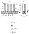
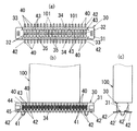
従来より、例えば図12〜図15に示すように、ソケット50とヘッダ70とで構成され、それぞれが実装されたプリント配線板(例えばFPCと硬質基板)の間を電気的に接続するコネクタが提供されている(例えば、特許文献1参照)。
Conventionally, for example, as shown in FIGS. 12 to 15, there is provided a connector that is composed of a
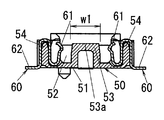
ソケット50は、図12及び図13に示すように、扁平な直方体状に形成された樹脂成型品からなるソケット本体51と、ソケット本体51に配設される複数のソケットコンタクト60とを具備する。ソケット本体51には長手方向に沿って差込溝52が形成され、この差込溝52の底面から細長の直方体状の突台部53が略垂直に突設されている。そして、差込溝52の両側の周壁54,54にはソケット本体11の長手方向に沿って複数のソケットコンタクト60が2列に並設されている。
As shown in FIGS. 12 and 13, the
ソケットコンタクト60は帯状の金属材を曲成することによって形成され、差込溝52内に臨む一端部にはヘッダコンタクト80に接触する接触部61が形成されており、ソケット本体11の樹脂成形時にインサートされている。また、差込溝52の外側に位置するソケットコンタクト60の一端側は、ソケット本体51の背面側(プリント配線板側)から外側に曲げられて周壁54と略垂直な方向に突出し、プリント配線板の導電パターンに半田固定される端子部62を先端部に形成してある。
The
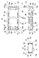
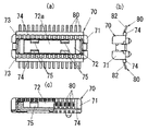
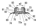
一方、ヘッダ70は、図14及び図15に示すように、扁平な直方体状に形成された樹脂成型品からなるヘッダ本体71と、ヘッダ本体71に配設されて複数のソケットコンタクト60にそれぞれ接触導通する複数のヘッダコンタクト80とを具備する。ヘッダ本体71には、ソケット本体51の突台部53と対向する部位に、この突台部53と嵌合する嵌合溝72がヘッダ本体71の長手方向に沿って形成されている。そして、ヘッダ本体71の嵌合溝72の両側の周壁73,73には、ヘッダ本体71の背面側(プリント配線板側)の縁に、周壁73から略垂直に突出する鍔部74が形成されている。また嵌合溝72の溝内には、嵌合時に加わる衝撃を分散させるために突台部53に設けたキー溝55に嵌合する嵌合突起75が4箇所に突設されている。
On the other hand, as shown in FIGS. 14 and 15, the
ヘッダコンタクト80は、帯状の金属材を曲成することによって形成され、周壁73の外表面に沿った部位の鍔部74側にはソケットコンタクト60の接触部61に接触する接触部81が形成され、鍔部74から突出する一端部にはプリント配線板の導電パターンに半田固定される端子部82が形成されており、インサート成形によりヘッダ本体71に同時成形されている。
The
このソケット50とヘッダ70とは、それぞれプリント配線板の導電パターンに、各ソケットコンタクト60の端子部62、各ヘッダコンタクト80の端子部82を半田固定することで実装される。そして、ヘッダ70をソケット50の差込溝52に挿入すると、ヘッダ70の嵌合溝72にソケット50の突台部53が嵌合するとともに、ソケットコンタクト60の接触部61がヘッダコンタクト80の接触部81に弾接して、ソケット50が実装されたプリント配線板とヘッダ70が実装されたプリント配線板の間が電気的に接続されるのである。
The
ところで、このコネクタはコンタクトのピッチが例えば0.4mm程度の狭ピッチのもので、携帯端末などの小型の電子機器に用いられるものであるが、電子機器のさらなる小型化のために、より小型のコネクタが要求されている。コネクタの長手方向(コンタクトの配列方向)の寸法はコンタクトのピッチや本数によって決まり、コンタクトのピッチは絶縁距離を確保するためにある程度の距離が必要であるから、コネクタを小型化するためには短手方向の寸法を小さくする必要がある。
上記構成のコネクタでは、ソケット本体51にヘッダ本体71を接続するための差込溝52が形成されているので、ソケット本体51の機械的強度が弱く、変形しやすいという問題があり、ソケット本体51の機械的強度を高めるために、差込溝52内に突台部53を設け、この突台部53が嵌る嵌合溝72をヘッダ本体71に設けている。また、ヘッダ本体71をプリント配線板に実装する際には、図示しない吸着ノズルの吸い込み口をヘッダ本体71の嵌合溝72の底面72aに当てて空気を吸引することで、ヘッダ本体71を吸着保持し、実装位置まで移送するのであるが、吸い込み口を吸着面に当てた時に隙間ができないように吸着面(つまり嵌合溝72の底面72a)を吸着ノズルの先端部よりも大きくしなければならず、そのためヘッダ本体71の短手方向において嵌合溝72の底面72aの幅W2を吸着ノズルの幅寸法よりも小さくすることができず、ヘッダ本体71の短手方向寸法の小型化に制約があるという問題があった。同様にソケット本体51をプリント配線板に実装する際には、吸着ノズルの吸い込み口をソケット本体51の突台部53の先端面53aに当てて空気を吸引することで、ソケット本体51を吸着保持し、実装位置まで移送するのであるが、吸い込み口を吸着面に当てた時に隙間ができないように吸着面(つまり突台部53の先端面53a)を吸い込み口よりも大きくしなければならず、そのためソケット本体51の短手方向において突台部53の先端面53aの幅W1を吸い込み口の孔径よりも小さくすることができず、ヘッダ本体71の短手方向寸法の小型化が阻害されてしまう。
In the connector having the above configuration, since the insertion groove 52 for connecting the
またヘッダコンタクト80の接触部81は、ヘッダ本体71の周壁73に沿って配置されており、接触部81の先端部(すなわち曲面部83の端部)がヘッダ本体71に係止する構造になっていないため、ヘッダ本体71の短手方向寸法を小型化した場合、ヘッダ本体71の剛性が低下し、ヘッダ70を斜めに抜き差しする際に、ヘッダ本体71が変形しやすくなって、接触部81の先端側が周壁73から浮き上がって剥がれてしまうという問題もあった。
The
本発明は上記問題点に鑑みて為されたものであり、その目的とするところは、吸着ノズルによる吸着面を確保しつつ小型化を図ったコネクタを提供することにある。 The present invention has been made in view of the above problems, and an object of the present invention is to provide a connector that is reduced in size while securing a suction surface by a suction nozzle.
上記目的を達成するために、本発明は、絶縁部材からなるヘッダ本体を具備したヘッダと、絶縁部材からなりヘッダが挿抜される差込溝が設けられたソケット本体を具備したソケットとを含み、ヘッダ本体の挿抜方向に沿う外表面に1乃至複数のヘッダコンタクトを保持させるとともに、差込溝にヘッダが挿入された際に差込溝の内側においてヘッダコンタクトに接触導通するように1乃至複数のソケットコンタクトをソケット本体に保持させたコネクタにおいて、ヘッダ本体におけるソケットとの対向面に取付溝を形成し、1乃至複数のヘッダコンタクトに、外表面に配置されてソケットコンタクトに接触する接触部と、該接触部のソケット側の端部からU字状に延出し、ヘッダ本体における取付溝の端面と外表面との間の部位を挟むようにしてヘッダ本体に取り付けられる取付部と、接触部の反対側の端部から側方に延出し、回路基板の導電パターンに接続される端子部とを設け、空気を吸引することでヘッダ本体を吸着保持する吸着ノズルを、吸着ノズルの吸い込み口が取付溝と連通するようにして対向面に当接させた状態で、吸い込み口の両側に少なくとも配置されるように、溝内を仕切る隔壁を取付溝の底部から開口部まで形成したことを特徴とする。 To achieve the above object, the present invention includes a header having a header body made of an insulating member, and a socket having a socket body made of an insulating member and provided with an insertion groove into which the header is inserted and removed. One or more header contacts are held on the outer surface along the insertion / removal direction of the header body, and when the header is inserted into the insertion groove, the one or more header contacts are electrically connected to the header contact inside the insertion groove. In the connector in which the socket contact is held on the socket body, a mounting groove is formed on the surface of the header body facing the socket, and the contact portion disposed on the outer surface of the one or more header contacts to contact the socket contact; Extending in a U-shape from the socket-side end of the contact portion so as to sandwich a portion between the end surface of the mounting groove in the header body and the outer surface Then, a mounting portion that is attached to the header body and a terminal portion that extends laterally from the end opposite to the contact portion and is connected to the conductive pattern of the circuit board are provided, and the header body is A partition partitioning the inside of the groove is mounted so that the suction nozzle to be sucked and held is in contact with the opposite surface so that the suction port of the suction nozzle communicates with the mounting groove. The groove is formed from the bottom to the opening.
請求項1の発明によれば、ヘッダ本体におけるソケットとの対向面には取付溝が形成され、ヘッダコンタクトに設けたU字状の取付部で、取付溝の端面と外表面との間の部位を挟持することによって、ヘッダコンタクトがヘッダ本体に取り付けられているので、ヘッダの挿抜時にヘッダ本体が変形したとしても取付部の先端が取付溝の端面に係止しているから、ヘッダコンタクトがヘッダ本体から剥がれるのを防止でき、且つ、吸着ノズルの吸い込み口が取付溝と連通するようにしてソケットとの対向面に吸着ノズルを当接させた状態で、吸い込み口の両側に少なくとも配置されるように、溝内を仕切る隔壁を取付溝の底部から開口部まで形成しているので、取付溝の溝幅を吸着ノズルの幅よりも狭くでき、したがってヘッダ本体に設けた溝の底面に吸着ノズルを当接させる従来例に比べてヘッダコンタクトの配列方向と略直交する方向のヘッダ本体の幅寸法を小さくでき、吸着ノズルによる吸着面を確保しつつ、ヘッダ本体の小型化を図ることができる。 According to the first aspect of the present invention, a mounting groove is formed on the surface of the header body facing the socket, and a portion between the end surface of the mounting groove and the outer surface at the U-shaped mounting portion provided in the header contact. Since the header contact is attached to the header body by sandwiching the header body, even if the header body is deformed when the header is inserted or removed, the tip of the attachment portion is locked to the end surface of the attachment groove. It can be prevented from peeling off from the main body, and is arranged at least on both sides of the suction port with the suction nozzle in contact with the surface facing the socket so that the suction port of the suction nozzle communicates with the mounting groove. In addition, since the partition wall that partitions the inside of the groove is formed from the bottom of the mounting groove to the opening, the groove width of the mounting groove can be made narrower than the width of the suction nozzle, and therefore the groove provided in the header body Compared to the conventional example in which the suction nozzle is brought into contact with the bottom surface, the width of the header body in the direction substantially perpendicular to the header contact arrangement direction can be reduced, and the header body can be reduced in size while securing the suction surface by the suction nozzle. be able to.
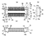
以下に本発明の実施の形態を図1〜図11に基づいて説明する。本実施形態のコネクタは、例えばフレキシブルプリント配線板と硬質基板であるプリント配線板との間を接続する基板対基板用のコネクタであり、図2に示すように複数のソケットコンタクト20および各ソケットコンタクト20が並べて配設されたソケット本体11を具備したソケット10と、各ソケットコンタクト20に接触導通する複数のヘッダコンタクト40および各ヘッダコンタクト40が並べて配設されるヘッダ本体31を具備したヘッダ30とで構成される。
Hereinafter, embodiments of the present invention will be described with reference to FIGS. The connector of this embodiment is a board-to-board connector that connects, for example, a flexible printed wiring board and a printed wiring board that is a rigid board, and includes a plurality of
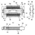
ソケット10のソケット本体11は、図5及び図6に示すように、扁平な略直方体状に形成された樹脂成型品からなり、ソケット本体11の長手方向に沿って矩形状に凹没した差込溝12が形成されている。ソケット本体11の樹脂成形時には複数のソケットコンタクト20がインサートされており、複数のソケットコンタクト20はソケット本体11の長手方向に沿って差込溝12の両側の周壁13,13に2列に並設されている。また、ソケット本体11におけるヘッダ30との対向面には、差込溝12の長手方向両端部の周縁から、ヘッダ30側に向かってコ字状のガイド壁15が突設されており、このガイド壁15には差込溝12から外側に行くほど突出量が大きくなるような傾斜面15aが形成されている。
As shown in FIGS. 5 and 6, the
各ソケットコンタクト20は帯状の金属材からなり、U字状に曲成されてソケット本体11の差込溝12周辺の長手方向に沿う周壁13の縁部を挟む形でソケット本体11に保持された保持部21と、保持部21における差込溝12の内側に位置する一端から保持部21とともにS字状を形成する形で延設され保持部21との間の距離を変化させる方向(すなわち、差込溝12へのヘッダ30の挿抜方向と交差する方向)に撓み可能な撓み部22と、保持部21における差込溝12の外側に位置する一端から外側に曲げられて周壁13と略垂直な方向に突出し、例えばプリント配線板の導電パターンに半田固定される帯状の端子部23とが連続一体に設けられている。また撓み部22には、保持部21から離れる方向に突出した接触凸部24(接触部)が曲げにより形成されており、この接触凸部24は上記挿抜方向と交差する方向に弾性的に突出している(図6参照)。
Each
また、ソケット本体11の長手方向の両端部には端子補強金具14がインサート成形により同時成形されている。端子補強金具14はソケット本体11の長手方向の両端部の底部から側方に突出する固定片14aと、長手方向の両端部にある一対の固定片14aの間を連結し、ソケット本体11内に埋設固定されるU字形の連結片14bとを備え、固定片14aは端子部23と略同一高さに配置されている。而してソケット10の端子部23をプリント配線板の導電パターンに半田固定する際に、固定片14aをプリント配線板のランドに半田固定することで、ソケット本体11の基板への固定強度を補強することができ、コネクタ嵌合時にソケットコンタクト20に加わるストレスを低減できる。
Moreover, the terminal
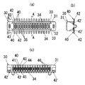
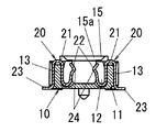
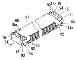
一方、ヘッダ30のヘッダ本体31は、図3及び図4に示すように、細長の略直方体状に形成された樹脂成型品からなり、ソケット本体11との対向面における短幅方向の中央部には、ヘッダコンタクト40が配設される部位に取付溝32が長手方向に沿って形成され、取付溝32の両側にある周壁33,33の背面側(ソケット10と反対側)の縁には周壁33から略垂直に突出する鍔部34が形成されている。そして、ヘッダ本体31の周壁33,33の外側面には、ヘッダ本体31の長手方向に沿って複数のヘッダコンタクト40が2列に並設されている。また取付溝32の溝内には、取付溝32の底部から開口部にかけて取付溝32を挟んで対向する周壁33,33の間を連結して溝内を仕切る複数の隔壁35がヘッダ本体31と一体に形成されており、各々の隔壁35はヘッダ本体31の長手方向において隣接するヘッダコンタクト40の間に配置されている。
On the other hand, as shown in FIGS. 3 and 4, the
各ヘッダコンタクト40は帯状の金属材を曲成することによって形成され、インサート成形によりヘッダ本体31に同時成形されており、ヘッダ本体31の背面側(基板側)の一端側が、鍔部34から周壁33と略垂直な方向に突出している。そして、各ヘッダコンタクト40には、周壁33の挿抜方向(図1の上下方向)に沿う外表面の鍔部34側に配置されて、ソケットコンタクト20の接触凸部24に接触する接触部41が形成されており、この接触部41の背面側から側方に延出し鍔部34から突出する一端部に、プリント配線板の導電パターンに半田固定される帯状の端子部42が形成されている。また、各ヘッダコンタクト40には、接触部41の先端側(ソケット10側)からU字状に延出し、取付溝32の端面と上記外表面との間の部位(すなわち周壁33)を挟むようにしてヘッダ本体31に取り付けられる取付部43が設けられており、ソケットコンタクト20の撓み部22に接触する取付部43の曲面部分(外表面側の曲がり部)の曲率半径を、撓み部22がこの曲面部分に引っ掛かって座屈しないような最小の曲率半径に設定してある。
Each
またヘッダ本体31の長手方向の両端部には、ヘッダコンタクト40のインサート成形時にロスピンとなるヘッダコンタクト40’をインサート成形により同時成形してあり、このヘッダコンタクト40’の端子部42’の先端位置がヘッダ本体31の短手方向の両側面と略同じになるように、他の信号接続用の端子部42に比べて端子部42’を短めに切断してある。そして、ヘッダコンタクト40の端子部42をプリント配線板の導電パターンに半田固定する際に、端子部42’をプリント配線板のランド49に半田固定することで、ヘッダ本体31の基板への固定強度を補強することができ、コネクタ嵌合時にヘッダコンタクト40に加わるストレスを低減できる。すなわちロスピンとなるヘッダコンタクト40’の端子部42’が端子補強金具として機能する。
In addition,
本実施形態のコネクタは上記のような構成を有し、ソケットコンタクト20の端子部23およびヘッダコンタクト40の端子部42を、それぞれプリント配線板のような別々の基板(図示せず)に半田固定し、ソケット本体11の差込溝12にヘッダ30を差し込んで複数のソケットコンタクト20とヘッダコンタクト40とを各別に接触させることによって、プリント配線板の間を電気的に接続するのである。
The connector according to the present embodiment has the above-described configuration, and the
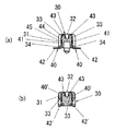
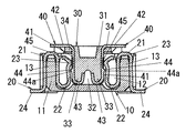
ここで、ソケット10およびヘッダ30をプリント配線板に実装する際には、図1及び図9に示すように吸着ノズル100をソケット10およびヘッダ30の吸着面に当てて空気を吸引することで、ソケット10およびヘッダ30を吸着保持して、実装位置まで移送するのであるが、ヘッダ30を吸着保持する際に吸着ノズル100の吸い込み口101が、ヘッダ本体31の前面に設けた取付溝32と連通するようにしてソケット10との対向面に当接させると、吸い込み口101の両側に隔壁35が配置されるから、隔壁35と周壁33,33と取付溝32の底部とで閉じた空間を形成でき、吸引時に空気が漏れることがなく、ヘッダ本体31を確実に吸引できる。この場合、取付溝32の溝幅は吸い込み口101の孔径よりも小さくできるから、ヘッダ本体31に設けた溝の底面に吸着ノズル100を当接させる従来例に比べてヘッダコンタクト40の配列方向と略直交する方向(短手方向)のヘッダ本体31の幅寸法を小さくでき、吸着ノズル100による吸着面を確保しつつ、ヘッダ本体31の小型化を図ることができる。なお本実施形態では複数の隔壁35を長手方向において隣接するヘッダコンタクト40の間に設けているので、吸い込み口101の位置が多少ずれたとしても、何れかの隔壁35が吸い込み口101の両側に配置されて、空気の漏れを確実に防止できるが、各吸い込み口101の両側に1つずつ隔壁35を設けても良い。
Here, when mounting the
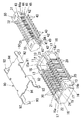
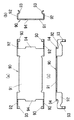
一方、ソケット10を吸着保持する際には、図2及び図7に示す吸着カバー90をソケット本体11に取り付け、吸着カバー90の主部91を吸着ノズル100で吸着することによってソケット10を保持して、移送する。吸着カバー90は薄肉の板金に抜き加工および曲げ加工を施すことによって形成され、矩形板状であって長手方向の寸法がソケット本体11に設けた一対のガイド壁15,15の間隔と略同じ寸法に形成されるとともに、短手方向の寸法がソケット本体11の短手方向寸法と略同じ寸法に形成されて、ソケット本体11におけるヘッダ30との対向面に載置される主部91と、主部91の長手方向に沿う両側縁の長手方向両端部から主部91と略直交する方向(ソケット本体11側)に突出し、先端側が長手方向における外側方向へ突出するように延出する脚片92と、各脚片92の長手方向両側部からソケット本体11側に突出し、中間部がソケット本体11の側面に近付く向きに曲成された可撓性を有する支持片93と、主部91の短幅方向に沿う両側縁の中央部に突設されて、コ字形のガイド壁15の内側面に嵌合する突片94とを備える。一方、ソケット本体11の長手方向における両端部には、短手方向の両側面の下側部(ヘッダ30と反対側の側部)に吸着カバー90の支持片93が係合する凹所16が形成されるとともに、この凹所16の上側の角部(つまりヘッダ30との対向面と短手方向の両側面とでできる角部)には、上側に行くほど短手方向の幅寸法が狭くなるように傾斜する傾斜面17が形成されている。
On the other hand, when sucking and holding the
而して、この吸着カバー90をソケット本体11に取り付ける際には、支持片93と傾斜面17との位置を合わせて吸着カバー90をソケット本体11に近付けると、支持片93が傾斜面17に当接して外側に撓められ、傾斜面17を超えて凹所16と係止することによって、吸着カバー90がソケット本体11に取着される(図10及び図11参照)。このとき主部91に設けた突片94がコ字形のガイド壁15の内側面と嵌合することで、主部91に平行な平面内での吸着カバー90の位置ずれを低減できる。尚、支持片93と凹所16とを係合させる際には傾斜面17と支持片93の弾性とで容易に係合できるようになっている。そして吸着カバー90をソケット本体11に取着した状態で、吸着カバー90の主部91に吸着ノズル100を当接させ、吸い込み口101から空気を吸引することによって吸着カバー90が吸着されるから、ソケット本体11を保持して移送させることができる。このようにソケット本体11に保持させた吸着カバー90を吸着ノズル100により吸着保持しているので、ソケット本体11の差込溝12内に突設した突台部の先端面を吸着面とした従来例に比べて、差込溝12の短手方向の幅寸法を小さくでき、結果ソケット本体11の短手方向寸法を小型にできる。
Thus, when attaching the
なおソケット本体11の短手方向に対向する一対の支持片93の間隔は、周壁13,13に設けた凹所16の間隔と略同じ寸法に形成されており、吸着カバー90をソケット本体11に保持させた状態(支持片93が凹所16と係合している状態)では支持片93が外側に撓められておらず、支持片93が凹所16と当接しているだけなので、保持状態において支持片93が凹所16と弾接している場合に比べて、リフロー半田時に成型品であるソケット本体11が熱で膨張したとしても、支持片93からソケット本体11に加わる荷重が小さくなり、ソケット本体51に割れなどが発生するのを防止できる。また凹所16はソケット本体11の長手方向両端部に設けられ、ソケット本体51の長手方向において補強用の固定片14aと位置をずらして設けてあるので、凹所16に係合する支持片93と固定片14aとを離すことができ、リフロー半田時に固定片14aに肉盛りした半田が支持片93に付着して吸着カバー90が外せなくなるのを防止できる。また吸着カバー90は、少なくともソケット本体11をプリント配線板に実装するまではソケット本体11に取着されているので、輸送時や実装途中に差込溝12内に塵埃が入り込んでソケットコンタクト20に付着し、電気的接続の信頼性が低下するのを防止する機能も有している。なお吸着カバー90をソケット本体11から離れる方向に引っ張れば、支持片93が外側に撓んで支持片93と凹所16との係合が外れるので、吸着カバー90を容易に取り外すことができ、上述のように保持状態において支持片93は凹所16と当接しているだけなので、吸着カバー90を引っ張る力が小さくてすみ、端子部23,23’に加わるストレスを小さくできる。
The distance between the pair of
また吸着カバー90は打抜き金型を用いて板金を打ち抜いた後、曲げ加工を施すことによって形成されており、その形状は長手方向の中心軸に対して線対称な形状となっている。したがって、長手方向の一端側の形状(脚片92や支持片93や突片94)を打ち抜くための打抜き金型と、長手方向の中間部を打ち抜くための打抜き金型とを用意しておけば、長手方向の中間部は矩形状に打ち抜くだけなので、ソケットコンタクト20の本数の違いによってソケット10の長手方向寸法が異なる場合でも、中間部用の打ち抜き金型により打ち抜く長さを変えることでソケットコンタクト20の本数の違いにも容易に対応でき、吸着カバー90を樹脂成型品とした場合のようにソケットコンタクト20の本数(すなわちソケット10の長手方向寸法)に合わせて個別の成型金型を用意する場合に比べて金型の製作費用を削減できる。
The
また、ソケット嵌合時にはソケットコンタクト20の接触凸部24が、ヘッダコンタクト40の先端部に設けたU字状の取付部43の外表面側の曲面部分に当接するのであるが、この曲面部分の曲率半径は、少なくともソケットコンタクト20がこの曲面部分に引っ掛かって座屈しないような最小の曲率半径に形成されているので、ソケットコンタクト20の座屈を防止しつつ、ヘッダ本体31の短手方向の寸法を小さくでき、コネクタの小型化を図ることができる。また、U字状の取付部43は、取付溝32の両側にある周壁33を挟むようにしてヘッダ本体31に取り付けられており、取付部43の一端が取付溝32の端面に係止しているので、コネクタ嵌合時にヘッダ本体31が変形したとしても、ヘッダコンタクト40がヘッダ本体31の表面から浮き上がって、剥がれることはない。
Further, when the socket is fitted, the contact
また、ソケット本体11の差込溝12にヘッダ30を差し込む際には、差込溝12の周縁部に設けたガイド壁15の傾斜面15aにヘッダ30がガイドされて、差込溝12に挿入されるため、ソケット本体11とヘッダ本体31との相対位置が多少ずれたとしても、ヘッダ30を差込溝12に容易に差し込めるようになっている。
When inserting the
またヘッダコンタクト40の接触部41において、ソケットコンタクト20の接触凸部24と接触する部位には突起44と凹部45が設けられており、図1に示すように、ヘッダ30がソケット10の差込溝12の奥まで挿入された状態において、接触凸部24は凹部45の両側部に接触しており、突起44は接触凸部24よりも差込溝12の底面側に位置している。突起44は、接触部41の端子部42が突出する側の面において長さ方向の中間よりも端子部42から離れた位置に突設されており、この突起44には、突出寸法を端子部42に近い位置ほど大きくする傾斜面44aが設けられている。また、凹部45は、図2(c)に示すように、接触凸部24の摺動方向に沿って延びた溝状であって、凹部45の内側にはそれぞれ接触凸部24の摺動方向に交差する方向(図中の左右方向)の端に近づくほど凹部45の深さ寸法を小さくする2つの平面である傾斜面が形成されており、凹部45の左右方向の断面形状をV字状に形成してある。
Further, in the
ここで、接触凸部24の摺動方向に交差する方向における凹部45の幅寸法は、接触凸部24の幅寸法よりも小さく形成され、凹部45は接触部41において接触凸部24の摺動範囲内に設けられており、ヘッダ30をソケット10の差込溝12に挿入する過程においては、接触部41における凹部45の両側部に接触凸部24が弾接する。また、接触凸部24において、突起44に接触する範囲と凹部45の両側部に接触する範囲とが重ならないように、ヘッダコンタクト40の幅方向における突起44の幅寸法は、凹部45の幅寸法よりもさらに小さく設定されている。
Here, the width dimension of the
この構成によれば、ソケット10とヘッダ30とが結合される前にソケットコンタクト20の接触凸部24やヘッダコンタクト40の接触部41に異物が付着していても、接触凸部24が接触部41の表面上を摺動する過程において異物を凹部45内に落としこめるから、凹部45が設けられていない場合に比べて接触凸部24と接触部41との間に異物が挟まる可能性が低くなる。つまり、異物による接触不良が防止され、且つ接触凸部24が凹部45の両側の2点で接触するから、接触信頼性を向上することができる。また、接触部41において接触凸部24の摺動範囲内に凹部45が設けられているので、接触凸部24の摺動範囲から外れた位置に凹部45を設ける場合に比べ、接触凸部24に付着した異物をより凹部45に落としこみやすい。
According to this configuration, even if foreign matter adheres to the contact
また、ヘッダ30を差込溝12から抜く力が加わると、ソケットコンタクト20の接触凸部24がヘッダコンタクト40の突起44に当接して抵抗力が付与されるから、コネクタが振動などを受けてもヘッダ30が差込溝12から抜けにくいという利点がある。なお、ヘッダ30を差込溝12に挿入する際にもソケットコンタクト20の接触凸部24はヘッダコンタクト40の突起44に当接するが、突起44の突出寸法を端子部42から離れた位置ほど小さくする傾斜面44aが突起44に設けられているので、ヘッダ30を差込溝12に挿入する際の抵抗はヘッダ30を差込溝12から抜く際の抵抗よりも小さくなる。また、接触凸部24において、突起44に接触する範囲と凹部45の両側部に接触する範囲とが重ならないように凹部45の位置と形状とを設定してあるから、接触凸部24が突起44の表面を摺動する際に接触凸部24に押された異物は凹部45に落としこめられ、接触凸部24と接触部41との間に挟まることがない。
Further, when a force for pulling out the
なお、本実施形態では接触凸部24が接触部41における凹部45の両側部に弾接しており、接触凸部24が接触部41の表面上を摺動する過程で異物を凹部45内に落とし込むことで接触凸部24と接触部41との間に異物が挟まる可能性を低減して、接触信頼性を向上させているが、接触凸部24と接触部41の形状およびその接触状態を上記の形態に限定する趣旨のものではなく、接触凸部24の接触部41に接触する面を、幅方向の中間部が両端部よりも接触部41側に突出するような形状(例えば曲面形状)に形成することで、幅方向の中間部が接触部41に設けた凹部45内に進入して、凹部45内の2つの傾斜面、又は、凹部45の開口縁に2点で接触するようにしても良く、接触凸部24と接触部41とが互いに平面で接触する場合に比べて接触凸部24と接触部41との接触面積が小さくなって、接触圧が増大するから、接触凸部24と接触部41との間から異物が排出されやすくなって、接触信頼性が向上する。
In this embodiment, the contact
30 ヘッダ
31 ヘッダ本体
32 取付溝
33 周壁
35 隔壁
40 ヘッダコンタクト
43 取付部
100 吸着ノズル
101 吸い込み口
30
Claims (1)
前記ヘッダ本体における前記ソケットとの対向面に取付溝を形成し、前記1乃至複数のヘッダコンタクトに、前記外表面に配置されて前記ソケットコンタクトに接触する接触部と、該接触部のソケット側の端部からU字状に延出し、前記ヘッダ本体における前記取付溝の端面と前記外表面との間の部位を挟むようにして前記ヘッダ本体に取り付けられる取付部と、前記接触部の反対側の端部から側方に延出し、回路基板の導電パターンに接続される端子部とを設け、空気を吸引することで前記ヘッダ本体を吸着保持する吸着ノズルを、吸着ノズルの吸い込み口が前記取付溝と連通するようにして前記対向面に当接させた状態で、前記吸い込み口の両側に少なくとも配置されるように、前記溝内を仕切る隔壁を前記取付溝の底部から開口部まで形成したことを特徴とするコネクタ。
Including a header having a header body made of an insulating member, and a socket having a socket body made of an insulating member and provided with an insertion groove into which the header is inserted and removed, and on an outer surface along the insertion / extraction direction of the header body One or more socket contacts are held in the socket body so that the header contacts are held in contact with the header contact inside the insertion groove when the header is inserted into the insertion groove. In the connector held in
A mounting groove is formed on a surface of the header body facing the socket, a contact portion disposed on the outer surface and in contact with the socket contact, and a socket side of the contact portion on the socket side. A mounting portion that extends in a U-shape from the end portion and is attached to the header body so as to sandwich a portion between the end surface of the mounting groove and the outer surface of the header body, and an end portion on the opposite side of the contact portion And a terminal portion that extends to the side and is connected to the conductive pattern of the circuit board. The suction nozzle sucks and holds the header body by sucking air, and the suction nozzle suction port communicates with the mounting groove. In such a manner that the partition wall is partitioned from the bottom of the mounting groove to the opening so as to be disposed at least on both sides of the suction port while being in contact with the opposing surface. Connector which is characterized in that form.
Priority Applications (8)
| Application Number | Priority Date | Filing Date | Title |
|---|---|---|---|
| JP2004107304A JP2005294035A (en) | 2004-03-31 | 2004-03-31 | Connector |
| KR1020057020391A KR100683029B1 (en) | 2004-03-31 | 2005-03-28 | Connector |
| EP05727262A EP1732183A4 (en) | 2004-03-31 | 2005-03-28 | CONNECTOR |
| CNB2005800002078A CN100446350C (en) | 2004-03-31 | 2005-03-28 | Connector |
| PCT/JP2005/005754 WO2005096456A1 (en) | 2004-03-31 | 2005-03-28 | Connector |
| US10/561,527 US7232317B2 (en) | 2004-03-31 | 2005-03-28 | Connector for electrically connecting electronic components |
| TW094110026A TWI249881B (en) | 2004-03-31 | 2005-03-30 | Connector |
| CNU2005200045691U CN2789955Y (en) | 2004-03-31 | 2005-03-31 | Connector |
Applications Claiming Priority (1)
| Application Number | Priority Date | Filing Date | Title |
|---|---|---|---|
| JP2004107304A JP2005294035A (en) | 2004-03-31 | 2004-03-31 | Connector |
Publications (1)
| Publication Number | Publication Date |
|---|---|
| JP2005294035A true JP2005294035A (en) | 2005-10-20 |
Family
ID=35064104
Family Applications (1)
| Application Number | Title | Priority Date | Filing Date |
|---|---|---|---|
| JP2004107304A Pending JP2005294035A (en) | 2004-03-31 | 2004-03-31 | Connector |
Country Status (7)
| Country | Link |
|---|---|
| US (1) | US7232317B2 (en) |
| EP (1) | EP1732183A4 (en) |
| JP (1) | JP2005294035A (en) |
| KR (1) | KR100683029B1 (en) |
| CN (2) | CN100446350C (en) |
| TW (1) | TWI249881B (en) |
| WO (1) | WO2005096456A1 (en) |
Cited By (1)
| Publication number | Priority date | Publication date | Assignee | Title |
|---|---|---|---|---|
| JP7044638B2 (en) | 2018-06-06 | 2022-03-30 | 日本航空電子工業株式会社 | How to produce the base material of the connector cover and the connector cover |
Families Citing this family (32)
| Publication number | Priority date | Publication date | Assignee | Title |
|---|---|---|---|---|
| JP4548219B2 (en) | 2005-05-25 | 2010-09-22 | パナソニック電工株式会社 | Socket for electronic parts |
| JP2007035291A (en) * | 2005-07-22 | 2007-02-08 | Hirose Electric Co Ltd | Electrical connector |
| CN2909582Y (en) * | 2006-04-20 | 2007-06-06 | 富士康(昆山)电脑接插件有限公司 | Electrical Connector Assembly |
| USD570289S1 (en) * | 2006-07-05 | 2008-06-03 | Japan Aviation Electronics Industry, Limited | Electrical connector |
| TWD121455S1 (en) * | 2006-09-12 | 2008-02-21 | 星電股份有限公司 | Connectors |
| JP4858050B2 (en) * | 2006-09-29 | 2012-01-18 | オムロン株式会社 | connector |
| TWM315443U (en) * | 2006-11-20 | 2007-07-11 | Hon Hai Prec Ind Co Ltd | Electrical card connector assembly |
| KR100968327B1 (en) * | 2007-03-14 | 2010-07-08 | 파나소닉 전공 주식회사 | Multipole Coaxial Connector |
| JP4492631B2 (en) * | 2007-03-27 | 2010-06-30 | パナソニック電工株式会社 | Cable connector |
| JP4717852B2 (en) | 2007-03-27 | 2011-07-06 | パナソニック電工株式会社 | Cable connector |
| CN201197011Y (en) * | 2008-01-29 | 2009-02-18 | 富士康(昆山)电脑接插件有限公司 | Edge clamping connector component |
| JP4726019B2 (en) * | 2008-09-16 | 2011-07-20 | 日本航空電子工業株式会社 | Connector device |
| JP2010182608A (en) * | 2009-02-09 | 2010-08-19 | Alps Electric Co Ltd | Connector |
| JP2011060590A (en) * | 2009-09-10 | 2011-03-24 | Hirose Electric Co Ltd | Electric connector with suction member |
| JP5557518B2 (en) * | 2009-12-18 | 2014-07-23 | モレックス インコーポレイテド | Terminal |
| HUE035183T2 (en) | 2011-09-30 | 2018-05-02 | Senju Metal Industry Co | Solder piece, chip solder, and method for manufacturing a chip solder |
| JP5188616B2 (en) * | 2011-10-07 | 2013-04-24 | ヒロセ電機株式会社 | Electrical connector with adsorption member, adsorption member, and mounting method of the electrical connector |
| US8986027B2 (en) | 2012-10-31 | 2015-03-24 | Japan Aviation Electronics Industry, Limited | Connector |
| US8888506B2 (en) * | 2013-01-29 | 2014-11-18 | Japan Aviation Electronics Industry, Limited | Connector |
| JP5970400B2 (en) * | 2013-03-19 | 2016-08-17 | 日本航空電子工業株式会社 | Conductive pattern type connector and connector unit |
| US9300064B2 (en) * | 2014-01-17 | 2016-03-29 | Japan Aviation Electronics Industry, Limited | Connector |
| JP6537890B2 (en) * | 2014-09-26 | 2019-07-03 | 日本航空電子工業株式会社 | connector |
| JP6655797B2 (en) * | 2016-04-28 | 2020-02-26 | パナソニックIpマネジメント株式会社 | Connectors, headers and sockets |
| CN106025642A (en) * | 2016-07-28 | 2016-10-12 | 欧品电子(昆山)有限公司 | Board-to-board connector component, female end connector and male end connector |
| JP6975626B2 (en) * | 2017-11-29 | 2021-12-01 | モレックス エルエルシー | Connector and connector assembly |
| CN111788112B (en) * | 2018-03-07 | 2022-06-28 | 本田技研工业株式会社 | Control unit arrangement structure for saddle-ride type vehicle |
| JP6498809B1 (en) * | 2018-03-08 | 2019-04-10 | 日本航空電子工業株式会社 | Electrical connector |
| JP6493611B1 (en) * | 2018-08-03 | 2019-04-03 | Smk株式会社 | Electrical connector |
| JP6816747B2 (en) * | 2018-10-01 | 2021-01-20 | Smk株式会社 | Electrical connector and electrical connector set |
| JP6816749B2 (en) * | 2018-10-11 | 2021-01-20 | Smk株式会社 | Electrical connector and electrical connector set |
| JP7148357B2 (en) * | 2018-10-18 | 2022-10-05 | モレックス エルエルシー | connector |
| JP6872053B1 (en) * | 2020-03-27 | 2021-05-19 | 日本航空電子工業株式会社 | Connector with suction cover |
Family Cites Families (14)
| Publication number | Priority date | Publication date | Assignee | Title |
|---|---|---|---|---|
| JPH075472B2 (en) * | 1986-06-27 | 1995-01-25 | 岩瀬コスフア株式会社 | External skin preparation |
| JPH0314608U (en) * | 1989-06-27 | 1991-02-14 | ||
| US5035658A (en) | 1990-02-21 | 1991-07-30 | Molex Incorporated | Electrical connector and terminal therefor |
| JP2598650Y2 (en) * | 1993-12-14 | 1999-08-16 | モレックス インコーポレーテッド | Electrical connector for connecting printed circuit boards |
| JP3014608U (en) * | 1994-12-07 | 1995-08-15 | モレックス インコーポレーテッド | Adsorption member for transporting connector |
| EP1278223B1 (en) | 2000-04-28 | 2009-10-14 | Panasonic Electric Works Co., Ltd. | High frequency relay |
| JP2002008753A (en) | 2000-06-16 | 2002-01-11 | Matsushita Electric Works Ltd | Connector |
| CN100361352C (en) | 2001-05-25 | 2008-01-09 | 松下电工株式会社 | Connector with a locking member |
| JP4205874B2 (en) * | 2001-06-26 | 2009-01-07 | 日本航空電子工業株式会社 | connector |
| JP2004055306A (en) | 2002-07-18 | 2004-02-19 | Yamaichi Electronics Co Ltd | Board connection connector |
| JP4000935B2 (en) * | 2002-07-23 | 2007-10-31 | 松下電工株式会社 | Low profile connector |
| JP2004111081A (en) * | 2002-09-13 | 2004-04-08 | Matsushita Electric Works Ltd | connector |
| KR100511180B1 (en) * | 2003-02-19 | 2005-08-30 | 재영솔루텍 주식회사 | Production method of electric-connector |
| US6827588B1 (en) * | 2003-06-12 | 2004-12-07 | Cheng Uei Precision Industry Co., Ltd. | Low profile board-to-board connector assembly |
-
2004
- 2004-03-31 JP JP2004107304A patent/JP2005294035A/en active Pending
-
2005
- 2005-03-28 US US10/561,527 patent/US7232317B2/en not_active Expired - Lifetime
- 2005-03-28 WO PCT/JP2005/005754 patent/WO2005096456A1/en not_active Ceased
- 2005-03-28 KR KR1020057020391A patent/KR100683029B1/en not_active Expired - Fee Related
- 2005-03-28 EP EP05727262A patent/EP1732183A4/en not_active Withdrawn
- 2005-03-28 CN CNB2005800002078A patent/CN100446350C/en not_active Expired - Lifetime
- 2005-03-30 TW TW094110026A patent/TWI249881B/en not_active IP Right Cessation
- 2005-03-31 CN CNU2005200045691U patent/CN2789955Y/en not_active Expired - Lifetime
Cited By (1)
| Publication number | Priority date | Publication date | Assignee | Title |
|---|---|---|---|---|
| JP7044638B2 (en) | 2018-06-06 | 2022-03-30 | 日本航空電子工業株式会社 | How to produce the base material of the connector cover and the connector cover |
Also Published As
| Publication number | Publication date |
|---|---|
| KR100683029B1 (en) | 2007-02-15 |
| TWI249881B (en) | 2006-02-21 |
| EP1732183A4 (en) | 2008-03-26 |
| CN100446350C (en) | 2008-12-24 |
| TW200536205A (en) | 2005-11-01 |
| US20060258227A1 (en) | 2006-11-16 |
| US7232317B2 (en) | 2007-06-19 |
| WO2005096456A1 (en) | 2005-10-13 |
| CN1879263A (en) | 2006-12-13 |
| CN2789955Y (en) | 2006-06-21 |
| KR20050116165A (en) | 2005-12-09 |
| EP1732183A1 (en) | 2006-12-13 |
Similar Documents
| Publication | Publication Date | Title |
|---|---|---|
| JP2005294035A (en) | Connector | |
| TWI745923B (en) | Connector and connector assembly | |
| JP5660756B2 (en) | Board to board connector | |
| CN103098307B (en) | Board-to-Board Connector | |
| TWI540801B (en) | Connector | |
| KR101919691B1 (en) | Connector | |
| US9065228B2 (en) | Connector | |
| CN102227851B (en) | Board-to-Board Connector | |
| EP2592698B1 (en) | Connector and connector connecting body | |
| KR101265438B1 (en) | Board-to-board connector | |
| JP2005294034A (en) | Connector | |
| JP2005294036A (en) | Connector and its manufacturing method | |
| CN103168395B (en) | Circuit board-circuit board connector | |
| US8277228B2 (en) | Connector set and jointer for use therein | |
| WO2019244549A1 (en) | Electric connector | |
| JP2008270100A (en) | Inter-board connector | |
| US6969274B2 (en) | Connector small in size and simple in structure | |
| US6406305B1 (en) | Electrical connector having compression terminal module therein | |
| CN110233370B (en) | Terminals, connectors and connector assemblies | |
| JP5673786B1 (en) | Electrical connector | |
| JP2009289627A (en) | Connector | |
| CN110838628B (en) | Disposable anti-theft connector | |
| JP7562768B2 (en) | connector | |
| JP2007149708A (en) | Manufacturing method of connector | |
| KR200337140Y1 (en) | Board-to-board connector |
Legal Events
| Date | Code | Title | Description |
|---|---|---|---|
| A621 | Written request for application examination |
Free format text: JAPANESE INTERMEDIATE CODE: A621 Effective date: 20060403 |
|
| A131 | Notification of reasons for refusal |
Free format text: JAPANESE INTERMEDIATE CODE: A131 Effective date: 20070116 |
|
| A02 | Decision of refusal |
Free format text: JAPANESE INTERMEDIATE CODE: A02 Effective date: 20070522 |