JP2005294025A - Press fit connector, its mounting method, and its mounting fixture - Google Patents
Press fit connector, its mounting method, and its mounting fixture Download PDFInfo
- Publication number
- JP2005294025A JP2005294025A JP2004107223A JP2004107223A JP2005294025A JP 2005294025 A JP2005294025 A JP 2005294025A JP 2004107223 A JP2004107223 A JP 2004107223A JP 2004107223 A JP2004107223 A JP 2004107223A JP 2005294025 A JP2005294025 A JP 2005294025A
- Authority
- JP
- Japan
- Prior art keywords
- press
- connector
- fit
- fitting
- pin
- Prior art date
- Legal status (The legal status is an assumption and is not a legal conclusion. Google has not performed a legal analysis and makes no representation as to the accuracy of the status listed.)
- Pending
Links
Images


Abstract
Description
本発明は、プリント基板に設けられた複数の端子電極とワイヤリング等との接合に用いられるプレスフィットコネクタ、及び同コネクタのプリント基板への装着方法、並びにその装着に用いられる装着用治具に関する。 The present invention relates to a press-fit connector used for joining a plurality of terminal electrodes provided on a printed circuit board and wiring, a method for mounting the connector on a printed circuit board, and a mounting jig used for mounting the same.
例えば車載電子制御ユニット(ECU)等にあって、各種電子部品が搭載されるプリント基板とワイヤリング等との接合には、いわゆるライトアングルタイプのコネクタが用いられることが多い。この種のコネクタは一般に、コネクタピンをプリント基板のスルーホールに挿入した状態でフローはんだ付けを施すことにより、プリント基板に設けられている複数の端子電極とそれらコネクタピンとの電気的な接続を図るようにしている。 For example, in an in-vehicle electronic control unit (ECU) or the like, a so-called right angle type connector is often used for joining a printed circuit board on which various electronic components are mounted to a wiring or the like. This type of connector is generally subjected to flow soldering in a state where the connector pins are inserted into the through holes of the printed circuit board, thereby achieving electrical connection between the plurality of terminal electrodes provided on the printed circuit board and the connector pins. I am doing so.
ただし、このようなはんだ付けによりコネクタピンと基板の端子電極とを接続する場合、その接続作業にかかる工数が無視できず、製造コストの増大も避けられない。そこで近年は、コネクタピンと基板の端子電極との接続に、例えば特許文献1に記載されているようなコネクタを応用したプレスフィットコネクタの採用が検討されている。上記ライトアングルタイプのコネクタにこのようなプレスフィットコネクタを採用することにより、上記はんだ付け等も不要となり、製造コストの低減が期待できるようになる。
ところで、従来のライトアングルタイプのコネクタは通常、複数のパワーピンと信号ピンとを備えている。しかも、これらパワーピンと信号ピンとでは、各々そのピン間隔(ピッチ)も異なっている。 By the way, a conventional right angle type connector usually includes a plurality of power pins and signal pins. Moreover, the power pin and the signal pin have different pin intervals (pitch).
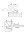
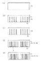
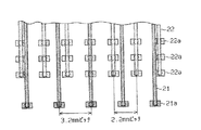
例えば一例として、図13に示すライトアングルタイプのプレスフィットコネクタでは、コネクタハウジング30から延出されるとともに、途中で直角に折り曲げられてプリント基板40のスルーホール41に装着される合計4段のピンを有している。そのうち、最上段の一列がパワーピン21であり、その下の3段はすべて信号ピン22となっている。そして、パワーピン21の横方向のピン間隔は約「3.2mm」であるのに対して、信号ピン22のピン間隔は約「2.2mm」となっている。なお、これらパワーピン21及び信号ピン22は共に、幅が約「0.64mm」の角状の導電性金属材料にて形成されている。
For example, in the right-angle type press-fit connector shown in FIG. 13, a total of four stages of pins that are extended from the
また、図14(a)〜(c)に三面図を示すように、このようなライトアングルタイプのプレスフィットコネクタには通常、パワーピン21及び信号ピン22の各々に、圧入用張り出し部21a及び22aとプレスフィット部21b及び22bとが設けられている。そして、同コネクタをプリント基板に接合する際には、櫛歯状の装着用治具を使用して上記圧入用張り出し部21a及び22aを押圧することにより上記プレスフィット部21b及び22bをプリント基板40のスルーホール41に圧入し、これによってその電気的及び機械的な接続を図ることになる。
Further, as shown in FIGS. 14A to 14C, the right angle type press-fit connector usually has a press-
しかし、上記のようなピン配列を採用するライトアングルタイプのプレスフィットコネクタでは、同コネクタをプリント基板40に装着する際に次のような不都合を生じることともなる。すなわち、同コネクタの平面図である図14(a)を図15に拡大して示すように、パワーピン21と信号ピン22との上述したピン間隔の相違により、パワーピン21が信号ピン22の圧入用張り出し部22aの一部を遮る(覆う)箇所が存在してしまう。したがって、このような箇所においては、この信号ピン22の圧入用張り出し部22aを上記櫛歯状の装着用治具で押圧する際に、圧入用張り出し部22aの片側のみが同治具によって押される、いわゆる片押し状態となる。このため図16に示すように、信号ピン22の圧入用張り出し部22aに対して上方から押圧荷重を印加すると、信号ピン22には、回転するように働くモーメントMが作用し、信号ピン22が傾いてしまう。そして結局は、信号ピン22の先端が横にずれ、プリント基板40のスルーホール41に対して真直ぐに装着することができなくなる。
However, a right angle type press-fit connector employing the pin arrangement as described above may cause the following inconvenience when the connector is mounted on the printed
本発明は、上記実情に鑑みてなされたものであり、たとえピン間隔が相違しているような場合であれ、それらすべてのピンをプリント基板に対して真直ぐに装着することのできるプレスフィットコネクタ、及びそのプリント基板への装着方法、及び同装置に用いられる装着用治具を提供することを目的とする。 The present invention has been made in view of the above circumstances, and even if the pin spacing is different, a press-fit connector capable of mounting all these pins straight to the printed circuit board, It is another object of the present invention to provide a mounting method for the printed circuit board and a mounting jig used in the apparatus.
こうした目的を達成するため、請求項1に記載のプレスフィットコネクタでは、コネクタハウジングから延出されて且つ、途中で直角に折り曲げられたライトアングルタイプのコネクタピンを備え、前記コネクタピンの先端部には、プリント基板のスルーホールに圧入されるプレスフィット部とこのプレスフィット部の前記スルーホールへの圧入を補助すべく前記コネクタピンが部分的に拡幅される態様で張り出された圧入用張り出し部とがそれぞれ設けられてなるプレスフィットコネクタとして、前記圧入用張り出し部に、当該圧入用張り出し部の押圧に際して前記コネクタピンの押圧方向以外への偏倚を規制する偏倚規制部を設けるようにした。 In order to achieve such an object, the press-fit connector according to claim 1 includes a right-angle type connector pin that extends from the connector housing and is bent at a right angle in the middle, and is provided at the tip of the connector pin. Is a press-fit portion that is press-fitted into a through hole of a printed circuit board, and a press-fit overhang portion that is bulged in such a manner that the connector pin is partially widened to assist the press-fitting of the press-fit portion into the through-hole. As a press-fit connector, each of which is provided with a displacement restricting portion for restricting the displacement of the connector pin in a direction other than the pressing direction when the press-fitting overhang portion is pressed.
このような構造によれば、前述のようにピン間隔が異なるなどに起因して、上記圧入用張り出し部の片押しが余儀なくされる場合であれ、上記偏倚規制部によってそれらコネクタピンの横ずれ等、押圧方向以外への偏倚が規制されるようになるため、同コネクタピンをプリント基板に対して真直ぐに装着することができるようになる。 According to such a structure, due to the difference in pin spacing as described above, even if the press-fitting overhanging part is forced to be pressed one side, the displacement restriction part causes the lateral displacement of the connector pins, etc. Since the deviation to the direction other than the pressing direction is restricted, the connector pin can be mounted straight on the printed circuit board.
また、請求項1に記載のプレスフィットコネクタにおいては、例えば請求項2に記載の発明によるように、前記偏倚規制部が、前記押圧方向に対して鋭角となる傾斜面を有する切り欠き部からなるもの、とすることが、その実現も容易であり、しかも、圧入用張り出し部に設けられた上記傾斜面と同圧入用張り出し部上方のコネクタピン側面とによる規制を通じて、上述したコネクタピンの横ずれ等、押圧方向以外への偏倚が好適に規制されるようになる。 In the press-fit connector according to claim 1, for example, as in the invention according to claim 2, the deviation restricting portion includes a notch portion having an inclined surface having an acute angle with respect to the pressing direction. It is also easy to realize, and the above-described lateral displacement of the connector pin and the like through regulation by the inclined surface provided on the press-fitting overhang and the side surface of the connector pin above the press-fitting overhang The deviation to the direction other than the pressing direction is preferably regulated.
また、偏倚規制部としてこのような傾斜面を設ける場合には、さらに請求項3に記載の発明のように、前記押圧方向に対して鋭角となる傾斜面の角度が、前記圧入用張り出し部の一方への押圧によって前記コネクタピンに生じる横方向へのモーメントを打ち消し得る角度に設定されてなるもの、とすることで、その偏倚規制効率もさらに高められるようになる。 In addition, when such an inclined surface is provided as the bias regulating portion, the angle of the inclined surface that is an acute angle with respect to the pressing direction is further set to be equal to that of the press-fitting overhang portion. By setting the angle to be able to cancel the lateral moment generated in the connector pin by pressing on one side, the deflection regulation efficiency can be further enhanced.
また、請求項1に記載のプレスフィットコネクタにおいては、例えば請求項4に記載の発明によるように、前記偏倚規制部が、前記圧入用張り出し部の前記コネクタピンとの付根部分に設けられて同圧入用張り出し部を押圧する治具の一部と係合される凹部からなるもの、として実現することもできる。偏倚規制部としてのこのような構造は、上記請求項2に記載の発明の構造にも通ずるが、この場合も、同偏倚規制部としての凹部と治具との係合を通じて、上述したコネクタピンの横ずれ等、押圧方向以外への偏倚が好適に規制されるようになる。 Further, in the press-fit connector according to claim 1, as in the invention according to claim 4, for example, the bias restricting portion is provided at a root portion of the press-fitting overhang portion with the connector pin. It can also be realized as a concave portion engaged with a part of a jig for pressing the overhanging portion. Such a structure as the deflection restricting portion also leads to the structure of the invention according to the second aspect, but in this case as well, through the engagement between the concave portion as the deviation restricting portion and the jig, the connector pin described above is used. The deviation to the direction other than the pressing direction such as the lateral displacement is suitably regulated.
同様に、請求項1に記載のプレスフィットコネクタにおいては、例えば請求項5に記載の発明によるように、前記偏倚規制部が、前記圧入用張り出し部の端部に設けられて同圧入用張り出し部を押圧する治具の一部と係合される突起部からなるもの、としてこれを実現することも有効である。この場合も、偏倚規制部としての突起部と治具との係合を通じて、上述したコネクタピンの横ずれ等、押圧方向以外への偏倚が好適に規制されるようになる。
Similarly, in the press-fit connector according to claim 1, for example, as in the invention according to
また、こうした突起部についてはこれを、例えば請求項6に記載の発明のように、
・前記圧入用張り出し部の端部上方に設けられてなるもの。
あるいは、請求項7に記載の発明のように、
・前記圧入用張り出し部の端部の前記コネクタハウジングから見て前方及び後方の少なくとも一方に設けられてなるもの。
そして、これらの構造において、さらには請求項8に記載の発明のように、
・前記圧入用張り出し部の端部を折り曲げ加工して形成されてなるもの。
等々、の態様での実現が可能である。これらいずれの場合であれ、それら偏倚規制部としての突起部と治具との係合を通じて、上述したコネクタピンの横ずれ等、押圧方向以外への偏倚を好適に規制することができる。また、特に請求項8に記載の発明のように、折り曲げ加工によって上記突起部を形成する場合、その曲げ代をコネクタピンと平行な方向に設けることが、例えば板金からプレスによる打ち抜き等によってコネクタピンを得る場合の材料取り数を稼ぐ上で有効である。すなわちこの場合、1枚の板金からより多くのコネクタピンを得ることができるようになる。
Further, for such a protrusion, for example, as in the invention according to claim 6,
-Provided above the end of the press-fitting overhang.
Or like invention of
-It is provided in at least one of the front and back as seen from the connector housing at the end of the press-fitting overhang.
In these structures, as in the invention according to claim 8,
-It is formed by bending the end of the press-fitting overhang.
And so on. In any of these cases, the displacement of the connector pin other than the pressing direction, such as the lateral displacement of the connector pin described above, can be suitably regulated through the engagement between the protrusion as the deflection regulating portion and the jig. In particular, as in the invention described in claim 8, when the projection is formed by bending, it is possible to provide the bending margin in a direction parallel to the connector pin. It is effective in earning the number of materials to obtain. That is, in this case, more connector pins can be obtained from one sheet metal.
また、請求項1に記載のプレスフィットコネクタにおいては、請求項9に記載の発明のように、前記偏倚規制部が、前記圧入用張り出し部を押圧する治具と当接される同圧入用張り出し部上面の面粗度の大きい部分からなるもの、としてこれを実現することも可能である。この場合には、上記圧入用張り出し部と治具との静止摩擦によって、コネクタピンの横ずれ等、押圧方向以外への偏倚が規制されるようになる。 In the press-fit connector according to claim 1, as in the invention according to claim 9, the press-fitting overhang for which the displacement restricting portion comes into contact with a jig that presses the overhang for press-fitting is provided. It is also possible to realize this as a part composed of a part having a large surface roughness on the part upper surface. In this case, due to the static friction between the press-fitting overhanging portion and the jig, the deviation of the connector pin in a direction other than the pressing direction, such as lateral displacement of the connector pin, is regulated.
また、これら請求項1〜9のいずれか一項に記載のプレスフィットコネクタにあっては、請求項10に記載の発明によるように、前記偏倚規制部を有する圧入用張り出し部が、前記コネクタピンの一側面にのみ設けられてなる、といった構造も有効である。上記偏倚規制部が、いわゆる片押しに対してそれらコネクタピンの偏倚を規制するものである以上、理論的には、このような構造で必要十分であることになる。 Further, in the press-fit connector according to any one of claims 1 to 9, as in the invention according to claim 10, the overhang portion for press-fitting having the bias regulating portion is the connector pin. A structure in which it is provided only on one side is also effective. Theoretically, such a structure is necessary and sufficient as long as the above-described bias regulating portion regulates the bias of the connector pins against so-called one-pressing.
一方、請求項11に記載のプレスフィットコネクタの装着方法では、コネクタハウジングから延出されて且つ、途中で直角に折り曲げられたライトアングルタイプの複数のコネクタピンを備え、それら各コネクタピンの先端部には、プリント基板のスルーホールに圧入されるプレスフィット部とこのプレスフィット部の前記スルーホールへの圧入を補助すべく前記コネクタピンが部分的に拡幅される態様で張り出された圧入用張り出し部とがそれぞれ設けられてなるプレスフィットコネクタを櫛歯状の治具を用いて前記プリント基板に装着する方法として、前記コネクタピンの各圧入用張り出し部には、当該圧入用張り出し部の前記治具による押圧に際して前記コネクタピンの押圧方向以外への偏倚を規制する偏倚規制部を設けておき、前記治具には、前記圧入用張り出し部の押圧時に前記偏倚規制部と係合される係合部を設けておき、それら偏倚規制部と係合部とが係合された状態で前記圧入用張り出し部を前記治具で押圧して前記プレスフィットコネクタを前記プリント基板に装着することとする。 On the other hand, the press-fit connector mounting method according to claim 11 includes a plurality of right angle type connector pins extending from the connector housing and bent at a right angle in the middle, and tip portions of these connector pins. Includes a press-fit portion that is press-fitted into a through-hole of a printed circuit board, and a press-fit overhang that is protruded in a manner in which the connector pin is partially widened to assist the press-fitting of the press-fit portion into the through-hole. As a method of mounting a press-fit connector, each of which is provided on the printed circuit board, using a comb-like jig, each press-fitting overhang portion of the connector pin is provided with the jig of the press-in overhang portion. A bias regulating part for regulating a deviation of the connector pin in a direction other than the pressing direction when pressed by a tool; The tool is provided with an engaging portion that is engaged with the displacement regulating portion when the press fitting overhang is pressed, and the press fitting overhanging portion is engaged with the displacement regulating portion and the engaging portion. The press-fit connector is mounted on the printed circuit board by pressing with the jig.
上記請求項1〜10のいずれか一項に記載の構造を有するプレスフィットコネクタに対しては、それぞれ上記偏倚規制部の形状に係合する形状を有する係合部を備える治具を用い、該治具によって上記圧入用張り出し部を押圧するようにすることで、同プレスフィットコネクタの前記プリント基板に対する装着を適正に、しかも確実に行うことができるようになる。 For the press-fit connector having the structure according to any one of claims 1 to 10, a jig provided with an engaging portion having a shape that engages with the shape of the displacement restricting portion is used. By pressing the press-fitting overhanging portion with a jig, the press-fit connector can be mounted on the printed board properly and reliably.
また一方、請求項12に記載のプレスフィットコネクタの装着用治具では、コネクタハウジングから延出されて且つ、途中で直角に折り曲げられたライトアングルタイプの複数のコネクタピンを備え、それら各コネクタピンの先端部には、プリント基板のスルーホールに圧入されるプレスフィット部とこのプレスフィット部の前記スルーホールへの圧入を補助すべく前記コネクタピンが部分的に拡幅される態様で張り出された圧入用張り出し部とがそれぞれ設けられてなるとともに、それら圧入用張り出し部には、同圧入用張り出し部の押圧に際して前記コネクタピンの押圧方向以外への偏倚を規制する偏倚規制部が設けられてなるプレスフィットコネクタの前記圧入用張り出し部を押圧して、前記プレスフィットコネクタを前記プリント基板に装着するプレスフィットコネクタの装着用治具として、前記各コネクタピンが挿入される櫛歯状の形状を有してなり、それらコネクタピンの前記圧入用張り出し部と当接される部分には、同圧入用張り出し部の前記偏倚規制部と係合される係合部を備えてなるもの、としてこれを形成する。 On the other hand, the press-fit connector mounting jig according to claim 12 includes a plurality of right-angle type connector pins extending from the connector housing and bent at right angles in the middle, and each of these connector pins. A press-fit portion that is press-fitted into a through-hole of the printed circuit board and a connector pin that is partially widened to assist in press-fitting the press-fit portion into the through-hole. The press-fitting overhangs are respectively provided, and the press-fitting overhangs are provided with deviation regulating portions for regulating the deviation of the connector pin in directions other than the pressing direction when the press-fitting overhangs are pressed. The press-fit connector is pressed against the press-fitting overhanging portion so that the press-fit connector is connected to the print base. As a mounting jig for a press-fit connector to be mounted on, it has a comb-like shape into which each of the connector pins is inserted, and in the portion that comes into contact with the press-fitting overhang portion of the connector pins, This is formed as a thing provided with the engaging part engaged with the said displacement control part of the overhang | projection part for the press injection.
装着用治具としてのこのような構造によって、上記請求項11に記載の装着方法も的確に実現されるようになる。
また、このような装着用治具としてはこれを、特に請求項13に記載の発明のように、前記櫛歯状の形状及び前記係合部の形状を分割する態様で複数枚の板材が積層されてなる構造とすることで、その実現、並びに製造も極めて容易となる。
With such a structure as a mounting jig, the mounting method according to claim 11 can also be realized accurately.
Further, as such a mounting jig, a plurality of plate members are laminated in such a manner that the comb-like shape and the shape of the engagement portion are divided, as in the invention of claim 13. By adopting such a structure, its realization and manufacture are extremely easy.
また、この請求項13に記載の装着用治具に関しては、さらに請求項14に記載の発明のように、前記複数枚の板材の各々が、放電加工によって前記櫛歯状の形状及び前記係合部の形状に対応する加工がなされてなるもの、とすることで、同装着用治具をより精密に製造することも可能となる。 In the mounting jig according to claim 13, as in the invention according to claim 14, each of the plurality of plate members is formed into the comb-like shape and the engagement by electric discharge machining. By making the processing corresponding to the shape of the part, the mounting jig can be manufactured more precisely.
そして、このような請求項14に記載の装着用治具に関して、請求項15に記載の発明のように、前記櫛歯状の形状及び前記係合部の形状に対応する加工がなされた前記複数枚の板材の各々はさらに、表面処理並びに熱処理が施されてなるもの、とすれば、当該治具として特に摩耗しやすい部分の強度を的確に高めることができるようにもなる。 Then, with regard to the mounting jig according to claim 14, as in the invention according to claim 15, the plurality of the plurality of the jigs that have been processed corresponding to the comb-like shape and the shape of the engagement portion. If each of the plate members is further subjected to surface treatment and heat treatment, the strength of the part that is particularly easily worn as the jig can be increased accurately.
(第1の実施の形態)
以下、本発明に係るプレスフィットコネクタ及びその装着方法及び装着用治具を具体化した第1の実施の形態について、図1〜図8に基づき説明する。なお、この実施の形態のプレスフィットコネクタも、コネクタ全体としての構造は、先の図14に例示した構造に準じたものを想定している。
(First embodiment)
Hereinafter, a first embodiment in which a press-fit connector, a mounting method thereof, and a mounting jig according to the present invention are embodied will be described with reference to FIGS. In the press-fit connector of this embodiment, the structure as the whole connector is assumed to conform to the structure illustrated in FIG.
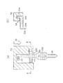
図1(a)は、本実施の形態にかかるプレスフィットコネクタの信号ピンの正面構造を、また図1(b)は、特にその圧入用張り出し部についてこれを拡大した構造をそれぞれ示したものである。 FIG. 1A shows the front structure of the signal pin of the press-fit connector according to the present embodiment, and FIG. 1B shows an enlarged structure, particularly for the press-fitting overhang portion. is there.
図1(a)に示すように、プレスフィットコネクタの信号ピン22の下部はプレスフィット部22bが形成されており、このプレスフィット部22bの上方には、同ピン22に対して対称となる態様で拡幅された圧入用張り出し部22aが形成されている。そして、この圧入用張り出し部22aを櫛歯状の装着用治具50を用いて押圧することによって、信号ピン22のプレスフィット部22bが図示しないプリント基板のスルーホールに嵌入、装着される。
As shown in FIG. 1A, a press-
ここで、信号ピン22の圧入用張り出し部22aの上方には、パワーピン21が存在しており、このパワーピン21が上記信号ピン22の圧入用張り出し部22aの片方を遮る構造となっている。このため、櫛歯状の装着用治具50を用いて信号ピン22をプリント基板に装着するとき、この櫛歯状の装着用治具50が圧入用張り出し部22aの片方(図中右側の圧入用張り出し部)しか押圧できないこととなり、いわゆる片押し状態となる。
Here, the
そして前述のように、信号ピン22の圧入用張り出し部22aの片方のみが櫛歯状の装着用治具50によって押圧される場合には通常、信号ピン22の先端に横ずれ偏倚が生じて、同ピン22をプリント基板に対して真直ぐに挿入することができなくなる。
As described above, when only one of the press-fitting
そこで、本実施の形態では、信号ピン22の上記張り出し部22aに、偏倚規制部として該信号ピン22の押圧方向に対して鋭角(傾斜角度α)となる傾斜面22cを有する切り欠き部を形成するようにしている。また、櫛歯状の装着用治具50の上記傾斜面22cと当接される部分にも、該傾斜面22cと係合する係合部52を併せて形成するようにしている。
Therefore, in the present embodiment, a notch portion having an
このため、図1(b)に示すように、櫛歯状の装着用治具50によって信号ピン22の圧入用張り出し部22aが片押しされる場合は、押圧力fの横方向の分力fcが生じるようになる。そして、この分力fcによって信号ピン22は上記傾斜面22cに沿って横にずれようとするが、このとき信号ピン22の側面は櫛歯状の装着用治具50に当接されて、その傾きが規制されるようになる。
For this reason, as shown in FIG. 1B, when the press-fitting
次に、櫛歯状の装着用治具50を用いてプレスフィットコネクタをプリント基板等に装着する際の装着方法について、図2〜図4に基づき説明する。
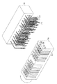
図2は、櫛歯状の装着用治具50及びプレスフィットコネクタの斜視構造を示す斜視図である。同図2に示すように、この櫛歯状の装着用治具50は、プレスフィットコネクタのパワーピン21と信号ピン22との配置及び各々のピンの圧入用張り出し部21aまたは22aの形状に合わせて、溝部51と係合部52とが形成されている。そして、同図2に矢印にて示すように、この櫛歯状の装着用治具50を180度回転させて、上記溝部51がプレスフィットコネクタの各ピンに向くように配置する。
Next, a mounting method when the press-fit connector is mounted on a printed circuit board or the like using the comb-shaped mounting
FIG. 2 is a perspective view showing a perspective structure of the comb-like mounting
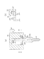
また、図3(a)及び(b)は、櫛歯状の装着用治具50とプレスフィットコネクタとを組み付けた状態での正面構造、及びB−B'線に沿った断面構造をそれぞれ示したものである。この状態で、プレスフィットコネクタの各々のピンに形成されている張り出し部21a及び22aが櫛歯状の装着用治具50の係合部52によって押圧される状態となっている。またこのとき、プレスフィットコネクタの各ピンがその先端がプリント基板のスルーホールの位置に合わせて整列される。
FIGS. 3A and 3B respectively show a front structure in a state where the comb-like mounting
そして、図4(a)及び(b)は、櫛歯状の装着用治具50を用いてプレスフィットコネクタをプリント基板40に装着した状態での正面構造、及びB−B'線に沿った断面構造をそれぞれ示したものである。ここで、まずプレスフィットコネクタの各ピンの先端を数mm程度、プリント基板40のスルーホール41に仮挿入して、その後各コネクタピンの圧入用張り出し部21a及び22aに対して押圧荷重をかけることにより、それらコネクタピンをプリント基板40に挿入する。これによって、プレスフィットコネクタの各コネクタピンとプリント基板40にスルーホール41として設けられた各端子電極との電気的、機械的な接続が実現される。
4 (a) and 4 (b) are along the front structure when the press-fit connector is mounted on the printed
このように、櫛歯状の装着用治具50には、プレスフィットコネクタの各ピンの位置に合わせて溝部51が形成され、また各ピンの張り出し部21a及び22aの形状に合わせて係合部52が形成されている。以下、この櫛歯状の装着用治具50の構造及びその製造方法等についてさらに詳細に説明する。
Thus, the comb-like mounting
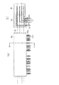
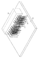
図5は、本実施の形態において使用される櫛歯状の装着用治具の組立構造を示す斜視図である。
同図5に示すように、櫛歯状の装着用治具50は、この例においては9枚の金属製板材(プレート)P1〜P9を積層して形成されている。これら9枚の板材P1〜P9は、それぞれプレスフィットコネクタのピンの配置及び圧入用張り出し部21a及び22aの形状に合わせて、放電加工などによって所望の形状に加工されている。このうち、最外側(図示手前側)から2枚目の板材P2は、プレスフィットコネクタのパワーピン21に対応するもので、この板材P2によってパワーピン21が押圧される。同様に、板材P4、P6、P8は、それぞれプレスフィットコネクタの3列の信号ピン22に対応するものである。また、その他の板材P1、P3、P5、P7及びP9は、プレスフィットコネクタのピンの前後方向のずれを防ぐために設けられるものである。
FIG. 5 is a perspective view showing an assembly structure of a comb-like mounting jig used in the present embodiment.
As shown in FIG. 5, the comb-like mounting
これら板材P1〜P9の各々の形状を図6(a)〜(e)に示す。
まず、図6(a)に示すように、最外側(図示手前側)の板材P1は、特にピンを通したり押圧したりしないため、溝部も係合部も形成されていない。また、図6(b)に示す板材P2は、プレスフィットコネクタのパワーピン21を押圧するもので、各溝部51の両側に規則的に係合部52が形成されている。一方、上述したように、プレスフィットコネクタの信号ピン22は、パワーピン21に遮られる部分があるため、これら信号ピン22に対応する板材P4、P6及びP8の溝部51及び係合部52は、図6(d)に示すように実際のピンの配置に合わせて、不規則的な形状となっている。また、図6(c)に示す板材P3は、パワーピン21を通すために、規則的な溝部51を有して形成されている。これに対して、図6(e)に示す板材P5、P7及びP9も溝部51のみが形成されているが、これらの溝部51は、それぞれ上記板材P4、P6及びP8の形状に合わせた形状となっている。なお、上記板材P4、P6、P8に形成された係合部52の詳細な構造は、例えば図6(d)のB部分を例として、その拡大図を図7に示す。
Each shape of these board | plate materials P1-P9 is shown to Fig.6 (a)-(e).
First, as shown in FIG. 6 (a), the outermost plate member P1 (not shown in the figure) does not pass through or press a pin in particular, so that neither a groove portion nor an engaging portion is formed. Moreover, the board | plate material P2 shown in FIG.6 (b) presses the
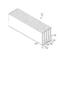
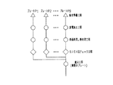
本実施の形態ではこのように、9枚の板材P1〜P9の積層構造として櫛歯状の装着用治具50を構成している。次にこの櫛歯状の装着用治具50の具体的な製造方法について、図8を参照して説明する。
In this embodiment, the comb-like mounting
同図8に示すように、まず9枚の板材P1〜P9を準備し、それから各板材に対してワイヤ放電加工によって所望の形状に加工する。このように、櫛歯状の装着用治具50全体としての複雑な形状が個々の比較的簡単な形状に分割されるため、この櫛歯状の装着用治具50の製造がより簡易なものとり、複雑なピン配置に対応する複雑な治具形状の場合も容易に製作することが可能となる。また、この放電加工により、精密な加工が実現されるようになる。
As shown in FIG. 8, first, nine plate materials P1 to P9 are prepared, and then each plate material is processed into a desired shape by wire electric discharge machining. Thus, since the complicated shape of the comb-shaped mounting
次に、櫛歯状の装着用治具50を構成する板材P1〜P9の各々に対して、表面処理及び熱処理を施す。これによって、耐磨耗性や強度、硬度などの治具として望ましい特性を必要に応じて得ることができるようになる。また、本実施の形態では、ピンと当たる部分については、その表面の面粗度が他の部分よりも大きくなるように表面処理を施している。これにより、ピンと櫛歯状の装着用治具50とが当たるときに、摩擦力が増大するため、ピンの傾きを規制する効果が一層高められるようになる。
Next, surface treatment and heat treatment are performed on each of the plate materials P1 to P9 constituting the comb-shaped mounting
そして最後の工程として、上記加工、表面処理及び熱処理された各板材P1〜P9を積層して組み立てることによって、櫛歯状の装着用治具50が製造される。
以上説明したように、本実施の形態によれば、以下のような効果が得られるようになる。
As a final step, the comb-shaped mounting
As described above, according to the present embodiment, the following effects can be obtained.
(1)プレスフィットコネクタの信号ピン22の圧入用張り出し部22aに、この信号ピン22の傾きを規制する傾斜面22cを設けることとした。これによって、信号ピン22が傾こうとするときに、該信号ピン22は櫛歯状の装着用治具50に当たり、これにより、その傾きが規制されるようになる。
(1) An
(2)信号ピン22の圧入用張り出し部22aに形成された傾斜面22cと係合する係合部52有する櫛歯状の装着用治具50を用いて、プレスフィットコネクタをプリント基板等に装着することで、プレスフィットコネクタを容易に装着することができるようになる。
(2) A press-fit connector is mounted on a printed circuit board or the like using a comb-shaped mounting
(3)また、上記プレスフィットコネクタ装着用の櫛歯状の装着用治具50は、9枚の板材P1〜P9を積層することで形成されている。これら9枚の板材P1〜P9に対して、それぞれ放電加工によってピンの配置及び押圧用張り出し部21a及び22aの形状に応じて、所望の形状に加工することで、複雑な形状を有する櫛歯状の装着用治具50の製作が容易なものとなる。
(3) The press-fit connector mounting comb-shaped mounting
なお、上記第1の実施の形態において、圧入用張り出し部22aに押圧方向に形成した傾斜面の傾斜角度αについてはこれを、前述した横方向の分力fcや冶具との摩擦力を考慮して、圧入用張り出し部22aの一方への押圧によって信号ピン22に生じる横方向へのモーメントを打ち消し得る角度に設定することがより望ましい。
In the first embodiment, the inclination angle α of the inclined surface formed in the pressing direction on the press-fitting
(第2の実施の形態)
次に、本発明に係るプレスフィットコネクタ及びその装着方法及び装着用治具を具体化した第2の実施の形態について、図9を参照して詳細に説明する。
(Second Embodiment)
Next, a second embodiment that embodies the press-fit connector, the mounting method, and the mounting jig according to the present invention will be described in detail with reference to FIG.
なお、本実施の形態のプレスフィットコネクタは、先の第1の実施の形態において、その張り出し部22aに形成される偏倚規制部としての傾斜面22cに代えて、図9に示す態様で張り出し部22aの端部に櫛歯状の装着用治具50の一部と係合される突起部22dを設けたものである。その他の点は、先の第1の実施の形態と同様であり、ここでのそれら共通する部分についての重複する説明は割愛する。また、本実施の形態では、プレスフィットコネクタの装着方法及び装着用治具についても先の第1の実施の形態に準じたものとなっているため、その詳細な説明についても割愛する。
Note that the press-fit connector of the present embodiment is different from the first embodiment in that the overhanging portion is in the form shown in FIG. 9 instead of the
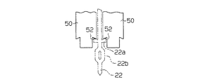
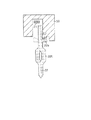
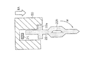
図9(a)は、本実施の形態にかかるプレスフィットコネクタの信号ピン22についてその装着用治具50との関係とともにその正面構造を示したものであり、また図9(b)は、特にその圧入用張り出し部22aについてその正面構造を拡大して示したものである。
FIG. 9A shows the front structure of the
これら図9(a)及び(b)に示すように、本実施の形態にあって、上記圧入用張り出し部22aの端部には、上方に突出する突起部22dが形成されている。そして、装着用治具50によって圧入用張り出し部22aが押圧されるとき、この突起部22dは装着用治具50の一部に設けられた係合部53と係合されることとなる。
As shown in FIGS. 9A and 9B, in the present embodiment, a protruding
これにより、装着用治具50によって圧入用張り出し部22aの片方のみが押される場合であっても、信号ピン22の偏倚がこれら突起部22d及び係合部53によって規制されるようになる。
Thus, even when only one of the press-fitting
なお、上記第2の実施の形態では、突起部22dを圧入用張り出し部22aの端部に形成することとしたが、この突起部22dに代えて、圧入用張り出し部22aの信号ピン22との付根部分に凹部を形成し、この凹部に係合されるかたちで装着用治具50に係合部を設けるようにしてもよい。また、この圧入用張り出し部22aの端部を上方に折り曲げることで、上記突起部22dを形成するようにしてもよい。
In the second embodiment, the
(第3の実施の形態)
次に、本発明に係るプレスフィットコネクタ及びその装着方法及び装着用治具を具体化した第3の実施の形態について、図11を参照して詳細に説明する。
(Third embodiment)
Next, a third embodiment that embodies the press-fit connector, the mounting method, and the mounting jig according to the present invention will be described in detail with reference to FIG.
なお、本実施の形態のプレスフィットコネクタは、先の第1の実施の形態において、その張り出し部22aに形成される偏倚規制部としての傾斜面22cに代えて、図10に示す態様で張り出し部22aの端部に櫛歯状の装着用治具50の一部と係合される突起部22eを設けたものである。その他の点は、先の第1の実施の形態と同様であり、ここでのそれら共通する部分についての重複する説明は割愛する。また、本実施の形態では、プレスフィットコネクタの装着方法及び装着用治具についても先の第1の実施の形態に準じたものとなっているため、その詳細な説明についても割愛する。
Note that the press-fit connector of the present embodiment is different from the first embodiment in that the overhanging portion is in the form shown in FIG. 10 instead of the
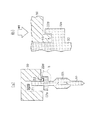
図10(a)は、本実施の形態にかかるプレスフィットコネクタの信号ピン22について装着用治具50との関係とともにその正面構造を示したものであり、また図10(b)は、特にその圧入用張り出し部22aについてその正面構造を拡大して示したものである。
FIG. 10A shows the front structure of the
これら図10(a)及び(b)に示すように、本実施の形態にあって、コネクタハウジングから見て前方及び後方の両方において、圧入用張り出し部22aの端部を折り曲げ加工して突起部22eが形成されている。そして、装着用治具50によって圧入用張り出し部22aが押圧されるとき、この突起部22eは装着用治具50の一部に設けられた係合部54と係合されることとなる。
As shown in FIGS. 10 (a) and 10 (b), in the present embodiment, the end of the press-fitting
これにより、装着用治具50によって圧入用張り出し部22aの片方のみが押される場合であっても、信号ピン22の偏倚がこれら突起部22e及び係合部54によって規制されるようになる。
As a result, even when only one of the press-fitting
なお、この第3の実施の形態では、圧入用張り出し部22aを長めに形成しておいてその端部を折り曲げることで突起部22eを形成することとしたが、図11に示すように、圧入用張り出し部22aの下方を長めに形成し、その部分を2分割してピン22の前後方向に折り曲げることにより突起部22fを形成するようにしてもよい。特にこの場合には、板金からプレスによる打ち抜き加工等によってコネクタピンを得る際、上記第3の実施の形態のものと比較して、それら各ピンの圧入用張り出し部22aを含めた絶対幅を節約することが可能となり、1枚の板金からより多くのコネクタピンを得ることができるようにもなる。
In the third embodiment, the protruding
(その他の実施の形態)
その他、上記各実施の形態に共通して変更可能な要素としては以下ようなものがある。
・上記各実施の形態では、9枚の板材P1〜P9を積層して櫛歯状の装着用治具50を形成することとしたが、ブロックを加工して一体形成の櫛歯状の装着用治具50を形成するようにしてもよい。
(Other embodiments)
In addition, the following elements can be changed in common with the above embodiments.
In each of the above embodiments, nine plate members P1 to P9 are stacked to form the comb-shaped mounting
・上記各実施の形態では、圧入用張り出し部22aをピンの両側に形成することとしたが、圧入用張り出し部22aの片方のみが押圧される場合でも信号ピンの傾きが規制されるため、例えば上記第1の実施の形態の変形例として図12に示すように、押圧されないもう一方の圧入用張り出し部22aについては、その配設を省略するようにしてもよい。これにより、隣接するピンの間隔(ピッチ)を減少することもでき、ピン構造の簡略化、またプリント基板の省スペース化が期待できるようになる。
In each of the above embodiments, the press-fitting
・上記各実施の形態では、装着用治具50のコネクタピンと当たる部分について、その表面の面粗度が他の部分より大きくなるように表面処理することとしたが、パワーピン21や信号ピン22からなるコネクタピンの上記装着用治具50と当たる部分についても、その面粗度が他の部分より大きくなるように表面処理を施すようにしてもよい。
In each of the above embodiments, the surface of the portion of the mounting
・上記各実施の形態では、放電加工によって櫛歯状の装着用治具50を構成する各板材P1〜P9を形成することとしたが、放電加工に限らず、旋盤での機械加工など、その他の加工方法を用いるようにしてもよい。また、プレスフィットコネクタとしてのピン配列等も、上記例示したものに限らず任意である。
In each of the above embodiments, the plate members P1 to P9 constituting the comb-shaped mounting
21…パワーピン、22…信号ピン、21a,22a…圧入用張り出し部、21b,22b…プレスフィット部、22c…傾斜面、22d,22e,22f…突起部、30…ハウジング、40…プリント基板、41…スルーホール、50…櫛歯状の装着用治具、51…溝部、52〜55…係合部、P1〜P9…板材。
DESCRIPTION OF
Claims (15)
前記圧入用張り出し部には、当該圧入用張り出し部の押圧に際して前記コネクタピンの押圧方向以外への偏倚を規制する偏倚規制部が設けられてなる
ことを特徴とするプレスフィットコネクタ。 A right-angle type connector pin extending from the connector housing and bent at a right angle in the middle is provided, and a press-fit portion that is press-fitted into a through-hole of the printed circuit board at the tip of the connector pin and the press-fit In press-fit connectors each provided with a press-fitting overhanging portion that is protruded in a manner in which the connector pin is partially widened to assist the press-fitting of the portion into the through-hole,
The press-fit connector, wherein the press-fitting overhanging portion is provided with a bias regulating portion that regulates deviation of the connector pin in a direction other than the pressing direction when the press-fitting overhanging portion is pressed.
請求項1に記載のプレスフィットコネクタ。 The press-fit connector according to claim 1, wherein the deviation restricting portion includes a notch portion having an inclined surface having an acute angle with respect to the pressing direction.
請求項2に記載のプレスフィットコネクタ。 The angle of the inclined surface, which is an acute angle with respect to the pressing direction, is set to an angle that can cancel a moment in the lateral direction generated in the connector pin due to pressing to one of the overhang portions for press-fitting. Press-fit connector.
請求項1に記載のプレスフィットコネクタ。 2. The press according to claim 1, wherein the bias restricting portion includes a recess that is provided at a base portion of the press-fitting overhang portion with the connector pin and is engaged with a part of a jig that presses the press-fitting overhang portion. Fit connector.
請求項1に記載のプレスフィットコネクタ。 The press-fit connector according to claim 1, wherein the bias restricting portion includes a protrusion that is provided at an end portion of the press-fitting overhang portion and engages with a part of a jig that presses the press-in overhang portion.
請求項5に記載のプレスフィットコネクタ。 The press-fit connector according to claim 5, wherein the protrusion is provided above an end of the press-fitting overhang.
請求項5に記載のプレスフィットコネクタ。 The press-fit connector according to claim 5, wherein the protrusion is provided on at least one of a front side and a rear side as viewed from the connector housing at an end of the press-fitting overhanging part.
請求項6または7に記載のプレスフィットコネクタ。 The press-fit connector according to claim 6, wherein the protrusion is formed by bending an end of the press-fitting overhang.
請求項1に記載のプレスフィットコネクタ。 The press-fit connector according to claim 1, wherein the bias restricting portion includes a portion having a large surface roughness on an upper surface of the press-fitting overhanging portion that is in contact with a jig that presses the press-fitting overhanging portion.
請求項1〜9のいずれか一項に記載のプレスフィットコネクタ。 The press-fit connector according to any one of claims 1 to 9, wherein a press-fitting overhang portion having the bias regulating portion is provided only on one side surface of the connector pin.
前記コネクタピンの各圧入用張り出し部には、当該圧入用張り出し部の前記治具による押圧に際して前記コネクタピンの押圧方向以外への偏倚を規制する偏倚規制部を設けておき、前記治具には、前記圧入用張り出し部の押圧時に前記偏倚規制部と係合される係合部を設けておき、それら偏倚規制部と係合部とが係合された状態で前記圧入用張り出し部を前記治具で押圧して前記プレスフィットコネクタを前記プリント基板に装着する
ことを特徴とするプレスフィットコネクタの装着方法。 A plurality of right angle type connector pins extending from the connector housing and bent at a right angle in the middle, and a press fit portion press-fitted into a through hole of the printed circuit board at the tip of each connector pin; A press-fit connector is provided with a press-fit connector that is provided with a press-fitting overhang portion that is protruded in such a manner that the connector pin is partially widened to assist press-fitting of the press-fit portion into the through hole. A method of mounting on the printed circuit board using a jig,
Each of the press-fitting overhang portions of the connector pin is provided with a bias regulating portion that regulates the deviation of the connector pin in a direction other than the pressing direction when the press-fitting overhang portion is pressed by the jig. An engagement portion that is engaged with the displacement restricting portion when the press-fit overhang portion is pressed is provided, and the press-fit overhang portion is fixed in the state in which the displacement restricting portion and the engagement portion are engaged. A method for mounting a press-fit connector, comprising: pressing the connector with a tool to mount the press-fit connector on the printed circuit board.
前記各コネクタピンが挿入される櫛歯状の形状を有してなり、それらコネクタピンの前記圧入用張り出し部と当接される部分には、同圧入用張り出し部の前記偏倚規制部と係合される係合部を備えてなる
ことを特徴とするプレスフィットコネクタの装着用治具。 A plurality of right angle type connector pins extending from the connector housing and bent at a right angle in the middle, and a press fit portion press-fitted into a through hole of the printed circuit board at the tip of each connector pin; The press-fit portion is provided with a press-fitting overhang portion that is protruded in a manner in which the connector pin is partially widened to assist the press-fitting of the press-fit portion into the through hole. Pressing the overhang portion for press-fitting of a press-fit connector provided with a displacement restricting portion for restricting the displacement of the connector pin in a direction other than the pressing direction when the overhang portion for press-fitting is pressed. A mounting jig for a press-fit connector to be mounted on the printed circuit board,
Each connector pin has a comb-like shape into which each connector pin is inserted, and the portion of the connector pin that comes into contact with the press-fitting overhanging portion is engaged with the deviation regulating portion of the press-fitting overhanging portion. A press-fit connector mounting jig, characterized by comprising an engaging portion.
請求項12に記載のプレスフィットコネクタの装着用治具。 The jig for mounting a press-fit connector according to claim 12, wherein a plurality of plate members are laminated in a manner that divides the comb-like shape and the shape of the engagement portion.
請求項13に記載のプレスフィットコネクタの装着用治具。 The jig for mounting a press-fit connector according to claim 13, wherein each of the plurality of plate members is processed by electric discharge machining to correspond to the comb-like shape and the shape of the engagement portion.
請求項14に記載のプレスフィットコネクタの装着用治具。 The mounting of the press-fit connector according to claim 14, wherein each of the plurality of plate members processed to have a shape corresponding to the comb-like shape and the shape of the engaging portion is further subjected to a surface treatment and a heat treatment. Jig.
Priority Applications (1)
| Application Number | Priority Date | Filing Date | Title |
|---|---|---|---|
| JP2004107223A JP2005294025A (en) | 2004-03-31 | 2004-03-31 | Press fit connector, its mounting method, and its mounting fixture |
Applications Claiming Priority (1)
| Application Number | Priority Date | Filing Date | Title |
|---|---|---|---|
| JP2004107223A JP2005294025A (en) | 2004-03-31 | 2004-03-31 | Press fit connector, its mounting method, and its mounting fixture |
Publications (1)
| Publication Number | Publication Date |
|---|---|
| JP2005294025A true JP2005294025A (en) | 2005-10-20 |
Family
ID=35326729
Family Applications (1)
| Application Number | Title | Priority Date | Filing Date |
|---|---|---|---|
| JP2004107223A Pending JP2005294025A (en) | 2004-03-31 | 2004-03-31 | Press fit connector, its mounting method, and its mounting fixture |
Country Status (1)
| Country | Link |
|---|---|
| JP (1) | JP2005294025A (en) |
Cited By (5)
| Publication number | Priority date | Publication date | Assignee | Title |
|---|---|---|---|---|
| EP2139075A2 (en) | 2008-06-27 | 2009-12-30 | Fujitsu Limited | Press-fit contact, connector, and connection structure of press-fit contact |
| JP2015133199A (en) * | 2014-01-10 | 2015-07-23 | 矢崎総業株式会社 | terminal insertion jig |
| WO2015124482A1 (en) * | 2014-02-24 | 2015-08-27 | Robert Bosch Gmbh | Plug connection element, connecting arrangement having a plurality of plug connection elements in an electrical device and press-in tool for forming a connecting arrangement |
| JP2017041341A (en) * | 2015-08-19 | 2017-02-23 | 住友電装株式会社 | Circuit board connector |
| WO2023219006A1 (en) * | 2022-05-13 | 2023-11-16 | 株式会社オートネットワーク技術研究所 | Press-fit terminal and substrate connector |
-
2004
- 2004-03-31 JP JP2004107223A patent/JP2005294025A/en active Pending
Cited By (6)
| Publication number | Priority date | Publication date | Assignee | Title |
|---|---|---|---|---|
| EP2139075A2 (en) | 2008-06-27 | 2009-12-30 | Fujitsu Limited | Press-fit contact, connector, and connection structure of press-fit contact |
| JP2015133199A (en) * | 2014-01-10 | 2015-07-23 | 矢崎総業株式会社 | terminal insertion jig |
| WO2015124482A1 (en) * | 2014-02-24 | 2015-08-27 | Robert Bosch Gmbh | Plug connection element, connecting arrangement having a plurality of plug connection elements in an electrical device and press-in tool for forming a connecting arrangement |
| JP2017041341A (en) * | 2015-08-19 | 2017-02-23 | 住友電装株式会社 | Circuit board connector |
| CN106469864A (en) * | 2015-08-19 | 2017-03-01 | 住友电装株式会社 | Circuit board use adapter |
| WO2023219006A1 (en) * | 2022-05-13 | 2023-11-16 | 株式会社オートネットワーク技術研究所 | Press-fit terminal and substrate connector |
Similar Documents
| Publication | Publication Date | Title |
|---|---|---|
| JP4804386B2 (en) | Press-fit contact | |
| JP2007535102A (en) | Pins, press-fit tools and methods for forming solderless electrical connections for solderless electrical connections to printed wiring boards | |
| WO2016021175A1 (en) | Connector, and header and socket used in connector | |
| JP2006210050A (en) | Connector | |
| JP4100694B2 (en) | connector | |
| JP7380930B2 (en) | connector | |
| JP4425730B2 (en) | Connector terminal manufacturing method | |
| JP3153473U (en) | Electrical connector | |
| JP6325389B2 (en) | Connector assembly | |
| JP2009140839A (en) | Connector terminal | |
| JP2005294025A (en) | Press fit connector, its mounting method, and its mounting fixture | |
| JP4626680B2 (en) | Holding member, electronic component, and electronic device | |
| JP4983387B2 (en) | Board connector | |
| JP4682706B2 (en) | connector | |
| JP2005135698A (en) | Press fit terminal | |
| JP4589100B2 (en) | Connecting structure with knock pin | |
| JP2011029123A (en) | Connector | |
| JP4075807B2 (en) | Terminal fitting and board connector | |
| JP2020030918A (en) | Connector and laminated board module | |
| JP2006313690A (en) | On-board connector | |
| JP2004342363A (en) | Connector and its tool for press fit | |
| JP2003303636A (en) | Electric connector | |
| JP2007242558A (en) | Terminal structure | |
| JP2006252809A (en) | Plug and connector | |
| JP2000058179A (en) | Contact |