JP2005293989A - Terminal for electrical connection - Google Patents
Terminal for electrical connection Download PDFInfo
- Publication number
- JP2005293989A JP2005293989A JP2004106236A JP2004106236A JP2005293989A JP 2005293989 A JP2005293989 A JP 2005293989A JP 2004106236 A JP2004106236 A JP 2004106236A JP 2004106236 A JP2004106236 A JP 2004106236A JP 2005293989 A JP2005293989 A JP 2005293989A
- Authority
- JP
- Japan
- Prior art keywords
- contact
- contact portion
- electrical connection
- connection
- terminal
- Prior art date
- Legal status (The legal status is an assumption and is not a legal conclusion. Google has not performed a legal analysis and makes no representation as to the accuracy of the status listed.)
- Granted
Links
Images
Landscapes
- Coupling Device And Connection With Printed Circuit (AREA)
Abstract
Description
本発明は、プリント基板やコネクタの絶縁体等に取付けられて使用される電気接続用端子に関するものである。 The present invention relates to an electrical connection terminal used by being attached to a printed circuit board, an insulator of a connector, or the like.
従来、この種の電気接続用端子としては、接続対象物との圧接により少なくとも一部が弾性変形するように形成され、一端側に接続対象物との接触部を有するとともに、接触部を接続対象物に対して凸状をなすように湾曲した平板状に形成し、接触部を接続対象物の導電部に幅方向に線接触させるようにしたものが知られている(例えば、特許文献1参照。)。また、接続対象物との接触部に接続対象物に向かって部分的に突出する突部を設け、突部を接続対象物に点接触させるようにしたものも知られている(例えば、特許文献2参照。)。
ところで、接触部を接続対象物に線接触させるようにしたものでは、接続対象物との接触範囲が広いため、局部的な摩耗が少なく、変位の繰り返しに対する耐久性は高いが、接触部分の傾斜等により接触位置が接触線方向に偏るなど、接触位置が不安定になり易く、接続信頼性に劣るという問題点があった。このような問題点は、接触部を面接触させるものにおいても同様に生じていた。また、接触部を接続対象物に点接触させるようにしたものでは、接続対象物との接触範囲が狭いため、接触位置が安定して接続信頼性を高めることはできるが、接触圧が集中的に加わってメッキ等の表面処理が削られるなど、局部的な摩耗を生じ易く、変位の繰り返しに対する耐久性に劣るという問題点があった。 By the way, in the case where the contact portion is in line contact with the connection target, the contact range with the connection target is wide, so there is little local wear and high durability against repeated displacement. For example, the contact position tends to become unstable due to the contact position being deviated in the contact line direction, and the connection reliability is poor. Such a problem also occurred in the case where the contact portion is in surface contact. In addition, in the case where the contact portion makes point contact with the connection object, the contact range with the connection object is narrow, so that the contact position can be stabilized and the connection reliability can be improved, but the contact pressure is concentrated. In addition, the surface treatment such as plating is scraped, and local wear is likely to occur, resulting in poor durability against repeated displacement.
本発明は前記問題点に鑑みてなされたものであり、その目的とするところは、接続信頼性のみならず変位の繰り返しに対する耐久性にも優れた電気接続用端子を提供することにある。 The present invention has been made in view of the above problems, and an object of the present invention is to provide an electrical connection terminal that is excellent not only in connection reliability but also in durability against repeated displacement.
本発明は前記目的を達成するために、接続対象物との圧接により少なくとも一部が弾性変形するように形成された電気接続用端子において、一端側に接続対象物との接触部を幅方向に少なくとも二つ有するとともに、一部の接触部を接続対象物と線接触または面接触するように形成し、他の接触部を接続対象物と点接触するように形成している。 In order to achieve the above object, the present invention provides an electrical connection terminal formed so that at least a part thereof is elastically deformed by pressure contact with a connection object, and a contact portion with the connection object is arranged in the width direction on one end side. While having at least two, some contact parts are formed in line contact or surface contact with the connection object, and other contact parts are formed in point contact with the connection object.
これにより、接続対象物と接触部とを圧接させることにより、一部の接触部が接続対象物と線接触または面接触し、他の接触部が接続対象物と点接触する。 Thereby, a part of contact part carries out a line contact or a surface contact with a connection target object, and another contact part carries out a point contact with a connection target object by press-contacting a connection target object and a contact part.
本発明の電気接続用端子によれば、接続対象物と線接触または面接触する一部の接触部によって変位の繰り返しに対する耐久性を高めることができ、接続対象物と点接触する他の接触部によって接続信頼性を高めることができるので、プリント基板やコネクタの絶縁体等に取付けて使用する場合に極めて有利である。 According to the electrical connection terminal of the present invention, the durability against repeated displacement can be enhanced by a part of the contact portion that makes line contact or surface contact with the connection object, and the other contact portion that makes point contact with the connection object. The connection reliability can be improved by this, so that it is extremely advantageous when used by being attached to a printed board or an insulator of a connector.
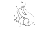
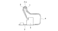
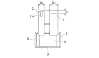
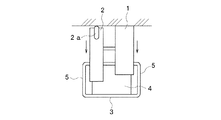
図1乃至図4は本発明の一実施形態を示すもので、図1は電気接続用端子の斜視図、図2はその側面図、図3はその正面図、図4はその屈曲状態を示す正面図である。 1 to 4 show an embodiment of the present invention. FIG. 1 is a perspective view of an electrical connection terminal, FIG. 2 is a side view thereof, FIG. 3 is a front view thereof, and FIG. It is a front view.
この電気接続用端子は導電性の金属板からなり、一端側に接続対象物と接触する第1及び第2の接触部1,2を有し、その他端側には図示しない基板に接続される接続部3が設けられている。各接触部1,2と接続部3との間には略U字状に屈曲する屈曲部4が設けられ、屈曲部4及び各接触部1,2は上下方向に弾性変形可能に形成されている。また、接続部3の幅方向両側には上方に延びる一対の側壁部5が設けられている。
This electrical connection terminal is made of a conductive metal plate, has first and
第1及び第2の接触部1,2は屈曲部4の一端側から斜め上方に二股状に延びる平板状に形成され、それぞれ上端側を略U字状に屈曲させている。また、各接触部1,2は上端側から斜め下方に延びるとともに、その先端側を略水平に形成されている。第1接触部1の上端側は幅方向に均一な高さに形成され、相手側導電体Aと線接触するようになっている。第2接触部2は、その上端側の幅方向中央に前記屈曲部分に沿って延びる突部2aを有し、突部2aを相手側導電体Aと点接触させるようになっている。また、図3に示すように第1の接触部1の幅寸法W1 は第2の接触部2の幅寸法W2 よりも大きく形成され、第2の接触部2は突部2aの上端が第1の接触部1の上端よりも高さHだけ上方に位置するように形成されている。
The first and
接続部3は平坦な板状に形成され、例えば半田付けによって基板に固定されることにより、基板に電気的に接続されるようになっている。
The connecting
屈曲部4は一端側が各接触部1,2に連続するように形成され、その他端側は接続部3に連続するように形成されている。
The
各側壁部5は上端側を第1及び第2の接触部1,2の先端側の上方に位置するように各接触部1,2の幅方向内側に向かって屈曲しており、各側壁部5の上端側には各接触部1,2の先端側がそれぞれ下方から係止するようになっている。
Each
以上のように構成された電気接続用端子においては、相手側導電体Aと第1及び第2の接触部1,2とを圧接させることにより、各接触部1,2及び屈曲部4が下方に弾性変形し、第1及び第2の接触部1,2と相手側導電体Aとが電気的に接続される。その際、第1の接触部1はその上端を相手側導電体Aと線接触し、第2の接触部2は突部2aの上端を相手側導電体Aと点接触する。また、第1の接触部1の幅寸法W1 は第2の接触部2の幅寸法W2 よりも大きく形成されているため、第1の接触部1と相手側導電体Aとの接触範囲を第1の接触部1の接触線方向に広くなる。この場合、接続前の第2の接触部2の突部2aの上端は第1の接触部1の上端よりも高さHだけ上方に位置していることから、相手側導電体Aが各接触部1,2にそれぞれ圧接すると、第2の接触部2の変位量は第1の接触部1よりも大きくなるため、第1の接触部1の幅寸法W1 が第2の接触部2の幅寸法W2 よりも大きく形成されていても、第1及び第2の接触部1,2と相手側導電体Aとの接触圧はほぼ等しくなる。
In the electrical connection terminal configured as described above, the
このように、本実施形態の電気接続用端子によれば、一端側に相手側導電体Aと接触する第1及び第2の接触部1,2を設け、第1の接触部1を相手側導電体Aと線接触するように形成し、第2の接触部2を相手側導電体Aと点接触するように形成したので、相手側導電体Aと線接触する第1の接触部1によって変位の繰り返しに対する耐久性を高めることができ、相手側導電体Aと点接触する第2の接触部2によって接続信頼性を高めることができる。
As described above, according to the electrical connection terminal of the present embodiment, the first and
この場合、第1及び第2の接触部1,2を互いに二股状に形成したので、各接触部1,2を容易に形成することができ、製造上極めて有利である。
In this case, since the first and
また、第1及び第2の接触部1,2をそれぞれ板状に形成するとともに、第2の接触部2には相手側導電体Aに接触する突部2aを設けたので、第1の接触部1と相手側導電体Aとの線接触及び第2の接触部2と相手側導電体Aとの点接触を確実に行うことができる。
Further, the first and
更に、第1の接触部1の幅寸法W1 を第2の接触部2の幅寸法W2 よりも大きく形成したので、第1の接触部1と相手側導電体Aとの接触範囲を第1の接触部1の接触線方向に広くすることができ、第1の接触部1と相手側導電体Aとの接続信頼性の向上を図ることができる。この場合、第2の接触部2を第1の接触部1よりも変位量が大きくなるように形成したので、第1の接触部1の幅寸法W1 が第2の接触部2の幅寸法W2 よりも大きく形成されていても、第1及び第2の接触部1,2と相手側導電体Aとの接触圧をほぼ等しくすることができ、第1及び第2の接触部1,2における接触圧の偏りを少なくすることができる。
Further, since the width dimension W1 of the
尚、前記実施形態では、第1の接触部1を相手側導電体Aに線接触させるようにしたものを示したが、面接触させるようにしてもよい。
In the above embodiment, the
また、前記実施形態では、第1の接触部1と第2の接触部2とを一つずつ設けたものを示したが、少なくとも一方を複数設けるようにしてもよい。
Moreover, although the said embodiment showed what provided the
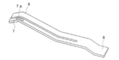
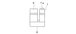
図5及び図6は本発明の他の実施形態を示すもので、図5は電気接続用端子の斜視図、図6はその側面図である。 5 and 6 show another embodiment of the present invention. FIG. 5 is a perspective view of an electrical connection terminal, and FIG. 6 is a side view thereof.
本実施形態の電気接続用端子は導電性の金属板からなり、細長い板状に形成されている。即ち、この電気接続用端子は、例えばコネクタに取付けて使用されるものであり、一端側に接続対象物と接触する第1及び第2の接触部6,7を有し、その他端側には図示しないコネクタ本体に保持される保持部8が設けられている。第1の接触部6の幅寸法は第2の接触部7の幅寸法よりも大きく形成され、第2の接触部7には図示しない相手側導電体に接触する突部7aが設けられている。
The electrical connection terminal of the present embodiment is made of a conductive metal plate and is formed in an elongated plate shape. That is, this electrical connection terminal is used by being attached to a connector, for example, and has first and
即ち、本実施形態の電気接続用端子では、前記実施形態と同様、第1の接触部6を相手側導電体と線接触させるとともに、第2の接触部7を相手側導電体と点接触させることができるので、相手側導電体と線接触する第1の接触部6によって変位の繰り返しに対する耐久性を高めることができ、相手側導電体と点接触する第2の接触部7によって接続信頼性を高めることができる。
That is, in the electrical connection terminal according to the present embodiment, the
1…第1の接触部、2…第2の接触部、2a…突部、6…第1の接触部、7…第2の接触部、7a…突部。
DESCRIPTION OF
Claims (4)
一端側に接続対象物との接触部を幅方向に少なくとも二つ有するとともに、
一部の接触部を接続対象物と線接触または面接触するように形成し、他の接触部を接続対象物と点接触するように形成した
ことを特徴とする電気接続用端子。 In the electrical connection terminal formed so that at least a part is elastically deformed by pressure contact with the connection object,
While having at least two contact portions in the width direction with the connection object on one end side,
A terminal for electrical connection, characterized in that a part of the contact part is formed so as to be in line contact or surface contact with the connection object, and the other contact part is formed so as to make point contact with the connection object.
第1の接触部及び第2の接触部を二股状に形成した
ことを特徴とする請求項1記載の電気接続用端子。 A first contact portion that makes line contact or surface contact with the connection object, and a second contact portion that makes point contact with the connection object,
The electrical connection terminal according to claim 1, wherein the first contact portion and the second contact portion are formed in a bifurcated shape.
ことを特徴とする請求項2記載の電気接続用端子。 3. The electricity according to claim 2, wherein the first contact portion and the second contact portion are each formed in a plate shape, and the second contact portion is provided with a protrusion that contacts the connection object. Connection terminal.
ことを特徴とする請求項2または3記載の電気接続用端子。 The second contact portion is formed so that the displacement amount is larger than that of the first contact portion, and the width dimension of the first contact portion is formed larger than the width dimension of the second contact portion. The electrical connection terminal according to claim 2 or 3.
Priority Applications (1)
| Application Number | Priority Date | Filing Date | Title |
|---|---|---|---|
| JP2004106236A JP4658508B2 (en) | 2004-03-31 | 2004-03-31 | Terminal for electrical connection |
Applications Claiming Priority (1)
| Application Number | Priority Date | Filing Date | Title |
|---|---|---|---|
| JP2004106236A JP4658508B2 (en) | 2004-03-31 | 2004-03-31 | Terminal for electrical connection |
Publications (2)
| Publication Number | Publication Date |
|---|---|
| JP2005293989A true JP2005293989A (en) | 2005-10-20 |
| JP4658508B2 JP4658508B2 (en) | 2011-03-23 |
Family
ID=35326702
Family Applications (1)
| Application Number | Title | Priority Date | Filing Date |
|---|---|---|---|
| JP2004106236A Expired - Fee Related JP4658508B2 (en) | 2004-03-31 | 2004-03-31 | Terminal for electrical connection |
Country Status (1)
| Country | Link |
|---|---|
| JP (1) | JP4658508B2 (en) |
Cited By (12)
| Publication number | Priority date | Publication date | Assignee | Title |
|---|---|---|---|---|
| WO2007060709A1 (en) * | 2005-11-22 | 2007-05-31 | Iriso Electronics Co., Ltd. | Connector |
| JP2008066083A (en) * | 2006-09-06 | 2008-03-21 | Molex Inc | Module socket |
| JP2011113894A (en) * | 2009-11-30 | 2011-06-09 | Takeuchi Kogyo Kk | Surface-mounted contact |
| KR101400745B1 (en) * | 2012-09-26 | 2014-05-29 | 대일티앤씨 주식회사 | A terminal contact |
| CN105048137A (en) * | 2014-04-22 | 2015-11-11 | Smk株式会社 | Terminal for connection of circuit boards |
| JP2016015293A (en) * | 2014-07-03 | 2016-01-28 | 第一精工株式会社 | Connector terminal |
| KR101591500B1 (en) | 2014-04-28 | 2016-02-04 | 주식회사 오킨스전자 | Terminal Contact for ZIF Connector |
| KR101605807B1 (en) * | 2014-04-28 | 2016-03-24 | 주식회사 오킨스전자 | ZIF Connector |
| JP2017162698A (en) * | 2016-03-10 | 2017-09-14 | Smk株式会社 | Contacting structure of contact |
| WO2018066817A1 (en) * | 2016-10-05 | 2018-04-12 | 삼성전자 주식회사 | Electronic device having flexible connector |
| JP2020087502A (en) * | 2018-11-15 | 2020-06-04 | 竹内工業株式会社 | Surface-mounted contact |
| US11031732B2 (en) | 2016-09-07 | 2021-06-08 | Yazaki Corporation | Lever-type connector |
-
2004
- 2004-03-31 JP JP2004106236A patent/JP4658508B2/en not_active Expired - Fee Related
Cited By (16)
| Publication number | Priority date | Publication date | Assignee | Title |
|---|---|---|---|---|
| WO2007060709A1 (en) * | 2005-11-22 | 2007-05-31 | Iriso Electronics Co., Ltd. | Connector |
| JP2008066083A (en) * | 2006-09-06 | 2008-03-21 | Molex Inc | Module socket |
| JP2011113894A (en) * | 2009-11-30 | 2011-06-09 | Takeuchi Kogyo Kk | Surface-mounted contact |
| KR101400745B1 (en) * | 2012-09-26 | 2014-05-29 | 대일티앤씨 주식회사 | A terminal contact |
| CN105048137A (en) * | 2014-04-22 | 2015-11-11 | Smk株式会社 | Terminal for connection of circuit boards |
| JP2015207475A (en) * | 2014-04-22 | 2015-11-19 | Smk株式会社 | Circuit board connection terminal |
| CN105048137B (en) * | 2014-04-22 | 2017-11-24 | Smk株式会社 | Circuit substrate terminal for connecting |
| KR101605807B1 (en) * | 2014-04-28 | 2016-03-24 | 주식회사 오킨스전자 | ZIF Connector |
| KR101591500B1 (en) | 2014-04-28 | 2016-02-04 | 주식회사 오킨스전자 | Terminal Contact for ZIF Connector |
| JP2016015293A (en) * | 2014-07-03 | 2016-01-28 | 第一精工株式会社 | Connector terminal |
| JP2017162698A (en) * | 2016-03-10 | 2017-09-14 | Smk株式会社 | Contacting structure of contact |
| US11031732B2 (en) | 2016-09-07 | 2021-06-08 | Yazaki Corporation | Lever-type connector |
| WO2018066817A1 (en) * | 2016-10-05 | 2018-04-12 | 삼성전자 주식회사 | Electronic device having flexible connector |
| US10777927B2 (en) | 2016-10-05 | 2020-09-15 | Samsung Electronics Co., Ltd. | Electronic device having flexible connector |
| JP2020087502A (en) * | 2018-11-15 | 2020-06-04 | 竹内工業株式会社 | Surface-mounted contact |
| JP7289497B2 (en) | 2018-11-15 | 2023-06-12 | 竹内工業株式会社 | surface mount contact |
Also Published As
| Publication number | Publication date |
|---|---|
| JP4658508B2 (en) | 2011-03-23 |
Similar Documents
| Publication | Publication Date | Title |
|---|---|---|
| KR101021012B1 (en) | connector | |
| JP3860823B2 (en) | Connector and portable terminal equipped with this connector | |
| JP6006356B2 (en) | Contact and connector using the contact | |
| JP3122168U (en) | Electrical connector | |
| JP4374074B1 (en) | Electrical connection terminal and connector using the same | |
| JP5871729B2 (en) | Housingless connector | |
| JP4592462B2 (en) | Board connector | |
| JP4802959B2 (en) | connector | |
| JP2018081869A (en) | connector | |
| JP2006302557A (en) | Base board to base board connector | |
| CN105375145A (en) | Contactor and connector having the same | |
| JP4658508B2 (en) | Terminal for electrical connection | |
| JP2003217711A (en) | Connector | |
| JP2017117734A (en) | connector | |
| JP4675200B2 (en) | Electrical connector | |
| JP5124789B2 (en) | Surface mount contact | |
| JP6574680B2 (en) | Terminal | |
| JP2005203139A (en) | Connector | |
| JP5629346B2 (en) | Electrical connection terminal and connector provided with the same | |
| CN205211988U (en) | Spring clamp and electric connector | |
| JP5023286B2 (en) | Surface mount contact | |
| JP2002170615A (en) | Terminal for electrical connection | |
| JP2003045521A (en) | Electrical connection terminal and electrical connector using the same | |
| JP2005108581A (en) | Connector system | |
| JP2010287356A (en) | Connector |
Legal Events
| Date | Code | Title | Description |
|---|---|---|---|
| A621 | Written request for application examination |
Free format text: JAPANESE INTERMEDIATE CODE: A621 Effective date: 20061222 |
|
| A977 | Report on retrieval |
Free format text: JAPANESE INTERMEDIATE CODE: A971007 Effective date: 20081030 |
|
| A131 | Notification of reasons for refusal |
Free format text: JAPANESE INTERMEDIATE CODE: A131 Effective date: 20090311 |
|
| A521 | Written amendment |
Free format text: JAPANESE INTERMEDIATE CODE: A523 Effective date: 20090511 |
|
| A02 | Decision of refusal |
Free format text: JAPANESE INTERMEDIATE CODE: A02 Effective date: 20091102 |
|
| A521 | Written amendment |
Free format text: JAPANESE INTERMEDIATE CODE: A523 Effective date: 20101108 |
|
| A01 | Written decision to grant a patent or to grant a registration (utility model) |
Free format text: JAPANESE INTERMEDIATE CODE: A01 |
|
| A61 | First payment of annual fees (during grant procedure) |
Free format text: JAPANESE INTERMEDIATE CODE: A61 Effective date: 20101224 |
|
| FPAY | Renewal fee payment (event date is renewal date of database) |
Free format text: PAYMENT UNTIL: 20140107 Year of fee payment: 3 |
|
| R150 | Certificate of patent or registration of utility model |
Ref document number: 4658508 Country of ref document: JP Free format text: JAPANESE INTERMEDIATE CODE: R150 Free format text: JAPANESE INTERMEDIATE CODE: R150 |
|
| R250 | Receipt of annual fees |
Free format text: JAPANESE INTERMEDIATE CODE: R250 |
|
| R250 | Receipt of annual fees |
Free format text: JAPANESE INTERMEDIATE CODE: R250 |
|
| R250 | Receipt of annual fees |
Free format text: JAPANESE INTERMEDIATE CODE: R250 |
|
| R250 | Receipt of annual fees |
Free format text: JAPANESE INTERMEDIATE CODE: R250 |
|
| R250 | Receipt of annual fees |
Free format text: JAPANESE INTERMEDIATE CODE: R250 |
|
| R250 | Receipt of annual fees |
Free format text: JAPANESE INTERMEDIATE CODE: R250 |
|
| R250 | Receipt of annual fees |
Free format text: JAPANESE INTERMEDIATE CODE: R250 |
|
| LAPS | Cancellation because of no payment of annual fees |