JP2005293974A - Direct methanol type fuel cell system - Google Patents
Direct methanol type fuel cell system Download PDFInfo
- Publication number
- JP2005293974A JP2005293974A JP2004105983A JP2004105983A JP2005293974A JP 2005293974 A JP2005293974 A JP 2005293974A JP 2004105983 A JP2004105983 A JP 2004105983A JP 2004105983 A JP2004105983 A JP 2004105983A JP 2005293974 A JP2005293974 A JP 2005293974A
- Authority
- JP
- Japan
- Prior art keywords
- fuel cell
- tank
- cell system
- gas
- methanol
- Prior art date
- Legal status (The legal status is an assumption and is not a legal conclusion. Google has not performed a legal analysis and makes no representation as to the accuracy of the status listed.)
- Granted
Links
- 239000000446 fuel Substances 0.000 title claims abstract description 108
- OKKJLVBELUTLKV-UHFFFAOYSA-N Methanol Chemical compound OC OKKJLVBELUTLKV-UHFFFAOYSA-N 0.000 title abstract description 285
- 239000007788 liquid Substances 0.000 claims abstract description 46
- 238000011084 recovery Methods 0.000 claims abstract description 24
- 238000000926 separation method Methods 0.000 claims abstract description 22
- 239000000126 substance Substances 0.000 claims abstract description 22
- 238000007865 diluting Methods 0.000 claims abstract description 4
- 239000000463 material Substances 0.000 claims description 14
- 239000012071 phase Substances 0.000 claims description 10
- 239000007800 oxidant agent Substances 0.000 claims description 9
- 230000001590 oxidative effect Effects 0.000 claims description 8
- 239000007791 liquid phase Substances 0.000 claims description 6
- 230000005611 electricity Effects 0.000 claims description 3
- 238000010248 power generation Methods 0.000 abstract description 20
- 239000000383 hazardous chemical Substances 0.000 abstract description 5
- 230000003247 decreasing effect Effects 0.000 abstract 1
- 230000002708 enhancing effect Effects 0.000 abstract 1
- 239000007864 aqueous solution Substances 0.000 description 40
- 239000007789 gas Substances 0.000 description 27
- 238000006243 chemical reaction Methods 0.000 description 23
- 239000002341 toxic gas Substances 0.000 description 18
- 239000003054 catalyst Substances 0.000 description 13
- 239000000243 solution Substances 0.000 description 13
- CURLTUGMZLYLDI-UHFFFAOYSA-N Carbon dioxide Chemical compound O=C=O CURLTUGMZLYLDI-UHFFFAOYSA-N 0.000 description 12
- XLYOFNOQVPJJNP-UHFFFAOYSA-N water Substances O XLYOFNOQVPJJNP-UHFFFAOYSA-N 0.000 description 12
- 239000012528 membrane Substances 0.000 description 10
- WSFSSNUMVMOOMR-UHFFFAOYSA-N Formaldehyde Chemical compound O=C WSFSSNUMVMOOMR-UHFFFAOYSA-N 0.000 description 9
- 239000003792 electrolyte Substances 0.000 description 8
- 239000001569 carbon dioxide Substances 0.000 description 6
- 229910002092 carbon dioxide Inorganic materials 0.000 description 6
- BDAGIHXWWSANSR-UHFFFAOYSA-N methanoic acid Natural products OC=O BDAGIHXWWSANSR-UHFFFAOYSA-N 0.000 description 4
- QVGXLLKOCUKJST-UHFFFAOYSA-N atomic oxygen Chemical compound [O] QVGXLLKOCUKJST-UHFFFAOYSA-N 0.000 description 3
- 238000001816 cooling Methods 0.000 description 3
- 238000010586 diagram Methods 0.000 description 3
- 238000003487 electrochemical reaction Methods 0.000 description 3
- 239000001301 oxygen Substances 0.000 description 3
- 229910052760 oxygen Inorganic materials 0.000 description 3
- 239000000047 product Substances 0.000 description 3
- OSWFIVFLDKOXQC-UHFFFAOYSA-N 4-(3-methoxyphenyl)aniline Chemical compound COC1=CC=CC(C=2C=CC(N)=CC=2)=C1 OSWFIVFLDKOXQC-UHFFFAOYSA-N 0.000 description 2
- OKTJSMMVPCPJKN-UHFFFAOYSA-N Carbon Chemical compound [C] OKTJSMMVPCPJKN-UHFFFAOYSA-N 0.000 description 2
- 239000007795 chemical reaction product Substances 0.000 description 2
- 235000019253 formic acid Nutrition 0.000 description 2
- 238000010438 heat treatment Methods 0.000 description 2
- CFQCIHVMOFOCGH-UHFFFAOYSA-N platinum ruthenium Chemical compound [Ru].[Pt] CFQCIHVMOFOCGH-UHFFFAOYSA-N 0.000 description 2
- 231100000331 toxic Toxicity 0.000 description 2
- 230000002588 toxic effect Effects 0.000 description 2
- UFHFLCQGNIYNRP-UHFFFAOYSA-N Hydrogen Chemical compound [H][H] UFHFLCQGNIYNRP-UHFFFAOYSA-N 0.000 description 1
- 229920000557 Nafion® Polymers 0.000 description 1
- 229910021536 Zeolite Inorganic materials 0.000 description 1
- 239000003463 adsorbent Substances 0.000 description 1
- 239000003570 air Substances 0.000 description 1
- 238000009835 boiling Methods 0.000 description 1
- 238000006555 catalytic reaction Methods 0.000 description 1
- 239000003638 chemical reducing agent Substances 0.000 description 1
- 238000002485 combustion reaction Methods 0.000 description 1
- 230000007423 decrease Effects 0.000 description 1
- 238000010790 dilution Methods 0.000 description 1
- 239000012895 dilution Substances 0.000 description 1
- HNPSIPDUKPIQMN-UHFFFAOYSA-N dioxosilane;oxo(oxoalumanyloxy)alumane Chemical compound O=[Si]=O.O=[Al]O[Al]=O HNPSIPDUKPIQMN-UHFFFAOYSA-N 0.000 description 1
- 238000007599 discharging Methods 0.000 description 1
- 230000000694 effects Effects 0.000 description 1
- 239000001257 hydrogen Substances 0.000 description 1
- 229910052739 hydrogen Inorganic materials 0.000 description 1
- 238000000034 method Methods 0.000 description 1
- 239000012466 permeate Substances 0.000 description 1
- BASFCYQUMIYNBI-UHFFFAOYSA-N platinum Substances [Pt] BASFCYQUMIYNBI-UHFFFAOYSA-N 0.000 description 1
- 231100000614 poison Toxicity 0.000 description 1
- 229920000642 polymer Polymers 0.000 description 1
- 239000007787 solid Substances 0.000 description 1
- 239000003440 toxic substance Substances 0.000 description 1
- 239000010457 zeolite Substances 0.000 description 1
Images

Classifications
-
- Y—GENERAL TAGGING OF NEW TECHNOLOGICAL DEVELOPMENTS; GENERAL TAGGING OF CROSS-SECTIONAL TECHNOLOGIES SPANNING OVER SEVERAL SECTIONS OF THE IPC; TECHNICAL SUBJECTS COVERED BY FORMER USPC CROSS-REFERENCE ART COLLECTIONS [XRACs] AND DIGESTS
- Y02—TECHNOLOGIES OR APPLICATIONS FOR MITIGATION OR ADAPTATION AGAINST CLIMATE CHANGE
- Y02E—REDUCTION OF GREENHOUSE GAS [GHG] EMISSIONS, RELATED TO ENERGY GENERATION, TRANSMISSION OR DISTRIBUTION
- Y02E60/00—Enabling technologies; Technologies with a potential or indirect contribution to GHG emissions mitigation
- Y02E60/30—Hydrogen technology
- Y02E60/50—Fuel cells
Landscapes
- Fuel Cell (AREA)
Abstract
Description
本発明はダイレクトメタノール燃料電池に関するものであり、特に、ダイレクトメタノール燃料電池の燃料の利用効率を向上させるシステム構成に関する。 The present invention relates to a direct methanol fuel cell, and more particularly to a system configuration that improves the fuel utilization efficiency of a direct methanol fuel cell.
燃料電池は、一般的にアノード極、電解質層及びカソード極を積層して燃料電池セルを構成し、アノード極に還元剤として水素などの燃料を、カソード極に酸化剤として酸素(例えば、空気中の酸素)を供給して、燃料供給と燃焼生成物の排出を連続的に行い、燃料と酸素とによって燃料電池セル内で電気化学反応を生じさせて電力を得る電池であり、様々な形式のものが開発されている。 In general, a fuel cell is formed by stacking an anode electrode, an electrolyte layer, and a cathode electrode, and a fuel such as hydrogen as a reducing agent is used as an anode electrode, and oxygen (for example, in the air) is used as an oxidizing agent at a cathode electrode. Is a battery that obtains electric power by continuously supplying fuel and discharging combustion products, and generating an electrochemical reaction in the fuel cell with the fuel and oxygen. Things are being developed.
中でも、固体高分子形燃料電池は、他の種類の燃料電池に比べて、作動温度が低く、出高い出力密度を持つ特徴が有り、メタノールと水を含む液体燃料を直接アノード極へ供給するだけで発電可能なダイレクトメタノール燃料電池(Direct Methanol Fuel Cell:DMFC)が脚光を浴びている。DMFCは、アノード極に燃料としてメタノール水溶液を、カソード極に一般的には空気を供給し、各セルにおいて電気化学反応を生じさせて発電すると共に、電気化学反応により生成した反応生成物を排出する。このとき、アノード極からは二酸化炭素が、カソード極からは生成水が、反応生成物として排出される。 Above all, solid polymer fuel cells are characterized by lower operating temperature and higher output density than other types of fuel cells, and only supply liquid fuel containing methanol and water directly to the anode. Direct methanol fuel cells (DMFC) that can generate electricity in the spotlight are attracting attention. The DMFC supplies an aqueous methanol solution as a fuel to the anode electrode and generally air to the cathode electrode, generates an electrochemical reaction in each cell, generates electric power, and discharges a reaction product generated by the electrochemical reaction. . At this time, carbon dioxide is discharged from the anode electrode and generated water is discharged from the cathode electrode as a reaction product.
そこでDMFCでは、高濃度メタノール水溶液タンクと高濃度のメタノール水溶液を希釈する希釈タンクと配置し、燃料としてアノード極にメタノール水溶液タンク供給する際に、カソード極で生成された生成水によって高濃度メタノール水溶液を所定の濃度に希釈して供給するシステムが開発されている(例えば、特許文献1参照)。
しかしながら、従来のダイレクトメタノール燃料電池のシステムでは、発電反応に使われずにアノード極から排出されたメタノールが発電反応の熱により気化し、発電反応により生じた二酸化炭素と共に外部へ排出され、再利用することができずにメタノールの利用効率を低下させてしまっているという問題があった。これにより、所定の濃度のメタノール水溶液を燃料として利用するダイレクトメタノール燃料電池システムにおいて、高濃度メタノールタンクのサイズから駆動時間が制限され、1つの高濃度メタノールタンクで使用できる時間が短くなってしまうという問題があった。 However, in the conventional direct methanol fuel cell system, methanol discharged from the anode electrode without being used in the power generation reaction is vaporized by the heat of the power generation reaction, and is discharged to the outside together with carbon dioxide generated by the power generation reaction for reuse. However, there was a problem that the utilization efficiency of methanol was lowered. As a result, in a direct methanol fuel cell system that uses a methanol aqueous solution of a predetermined concentration as a fuel, the driving time is limited due to the size of the high concentration methanol tank, and the time that can be used in one high concentration methanol tank is shortened. There was a problem.
また、発電反応による発熱に対して、空冷ファンを作動させて冷却させたり、起動時などにおいて効率良く発電を行うために、メタノール水溶液(メタノール水溶液バッファタンク)や燃料電池スタック(起動部)をヒータなどで加熱させたりすることにより、エネルギーを消費し、総合的な発電効率を低下させてしまうという問題があった。 Also, in order to cool the air generated by the air-cooling fan by operating the power generation reaction, or to efficiently generate power during startup, the methanol aqueous solution (methanol aqueous solution buffer tank) and the fuel cell stack (starting unit) are heated. However, there is a problem that energy is consumed and the overall power generation efficiency is lowered by heating.
更に、発電反応によりホルムアルデヒドや蟻酸などの有毒ガスが生成される虞があるが、これらの有毒な生成物を効率的に回収し、システム外部に排出するガスを無害化するのに有効な手段、或いは、その効果を継続的に持続させるための方法については、これまで考えられてこなかった。 Furthermore, there is a possibility that toxic gases such as formaldehyde and formic acid may be generated by the power generation reaction, but these toxic products are efficiently recovered and effective means for detoxifying the gas discharged outside the system, Or the method for maintaining the effect continuously has not been considered so far.
以上のような課題を鑑みて、本発明の請求項1記載の燃料電池システムは、高濃度の燃料を貯蔵する第1のタンクと、高濃度の燃料を希釈する第2のタンクと、第2のタンクで希釈された燃料をアノードに供給すると共に、酸化剤をカソードに供給することにより発電する燃料電池と、を備える燃料電池システムにおいて、少なくとも第1のタンクは交換可能に構成されることを特徴とする。
In view of the above problems, the fuel cell system according to
本発明の請求項1によれば、少なくとも第1のタンクは交換可能に構成されるので、第1のタンクが空になってしまった場合には、新たな第1のタンクと交換することで、駆動時間を延長することができる。
According to
本発明の請求項2記載の燃料電池システムは、請求項1記載の燃料電池システムにおいて、少なくとも燃料電池のアノードより排出される排出物質と第1のタンクとを熱交換する第1の熱交換器を備えることを特徴とする。
The fuel cell system according to
本発明の請求項2によれば、少なくとも燃料電池のアノードより排出される排出物質と第1のタンクとを熱交換する第1の熱交換器を備えるので、第1のタンクを加温することができると共に、燃料電池のアノードから発電反応による反応熱を伴って排出される排出物質を充分に冷却することができる。
According to
本発明の請求項3記載の燃料電池システムは、請求項2記載の燃料電池システムにおいて、排出物質と第2のタンクとを熱交換する第2の熱交換器を備え、第1の熱交換器と第2の熱交換器とを直列に接続することを特徴とする。
A fuel cell system according to
本発明の請求項3によれば、排出物質と第2のタンクとを熱交換する第2の熱交換器を備え、第1の熱交換器と第2の熱交換器とを直列に接続するので、燃料電池のアノードから発電反応による反応熱を伴って排出される排出物質を充分に冷却することができるほか、燃料電池のアノードへ供給される燃料を事前に加温し、燃料電池と同程度の温度の燃料をアノードへ供給することができる。
According to
本発明の請求項4記載の燃料電池システムは、請求項1記載の燃料電池システムにおいて、第1のタンクと一体に設けられ、少なくとも燃料電池のアノードより排出される排出物質の気相と液相とを分離する気液分離手段を備えることを特徴とする。
The fuel cell system according to
本発明の請求項4によれば、第1のタンクと一体に設けられ、少なくとも燃料電池のアノードより排出される排出物質の気相と液相とを分離する気液分離手段を備えるので、温度の低い第1のタンクにより気液分離手段が冷却されるため、気液分離が充分に行われるほか、気液分離手段を第1のタンクと共に交換することが可能となる。 According to the fourth aspect of the present invention, the apparatus includes gas-liquid separation means that is provided integrally with the first tank and separates at least the gas phase and the liquid phase of the exhaust material discharged from the anode of the fuel cell. Since the gas-liquid separation means is cooled by the first tank having a low value, the gas-liquid separation means is sufficiently performed, and the gas-liquid separation means can be exchanged together with the first tank.
本発明の請求項5記載の燃料電池システムは、請求項4記載の燃料電池システムにおいて、気液分離手段により分離された液相は、第2のタンクに導入されることを特徴とする。
The fuel cell system according to
本発明の請求項5によれば、気液分離手段により分離された液相は、第2のタンクに導入されるので、気化していた燃料は気液分離手段にて充分に冷却されて液相となり、第2のタンクへ導入されるため、燃料を効率よく回収することができる。 According to the fifth aspect of the present invention, since the liquid phase separated by the gas-liquid separation means is introduced into the second tank, the vaporized fuel is sufficiently cooled by the gas-liquid separation means to be liquid. Since it becomes a phase and is introduced into the second tank, the fuel can be efficiently recovered.
本発明の請求項6記載の燃料電池システムは、請求項1記載の燃料電池システムにおいて、第1のタンクと一体に設けられ、少なくとも燃料電池のアノードより排出される排出物質に含まれる有害物質を回収する有害物質回収手段を備えることを特徴とする。
A fuel cell system according to claim 6 of the present invention is the fuel cell system according to
本発明の請求項6によれば、第1のタンクと一体に設けられ、少なくとも燃料電池のアノードより排出される排出物質に含まれる有害物質を回収する有害物質回収手段を備えるので、有害物質回収手段を第1のタンクと共に交換することが可能となる。 According to the sixth aspect of the present invention, there is provided a hazardous substance recovery means that is provided integrally with the first tank and recovers at least a hazardous substance contained in the exhausted substance discharged from the anode of the fuel cell. The means can be exchanged with the first tank.
本発明の請求項7記載の燃料電池システムは、請求項6記載の燃料電池システムにおいて、気液分離手段により分離された気相は、有害物質回収手段に導入されることを特徴とする。 The fuel cell system according to claim 7 of the present invention is the fuel cell system according to claim 6, wherein the gas phase separated by the gas-liquid separation means is introduced into the harmful substance recovery means.
本発明の請求項7によれば、気液分離手段により分離された気相は、有害物質回収手段に導入されるので、気液分離手段により分離された外部へ排出する気相中に含まれる有害物質を回収することができる。 According to the seventh aspect of the present invention, since the gas phase separated by the gas-liquid separation means is introduced into the harmful substance recovery means, it is included in the gas phase discharged to the outside separated by the gas-liquid separation means. Harmful substances can be recovered.
本発明の請求項8記載の燃料電池システムは、請求項7記載の燃料電池システムにおいて、第1のタンクと接して配置され、気液分離手段と有害物質回収手段とを接続する配管を備えることを特徴とする。 A fuel cell system according to an eighth aspect of the present invention is the fuel cell system according to the seventh aspect, wherein the fuel cell system includes a pipe that is disposed in contact with the first tank and connects the gas-liquid separation means and the harmful substance recovery means. It is characterized by.
本発明の請求項8によれば、第1のタンクと接して配置され、気液分離手段と有害物質回収手段とを接続する配管を備えるので、気液分離手段により分離された気相を配管において冷却して液化するため、更に、燃料の回収を効率よく行うことができる。 According to the eighth aspect of the present invention, the gas tank separated from the gas-liquid separation means is provided with a pipe disposed in contact with the first tank and connecting the gas-liquid separation means and the harmful substance recovery means. In this case, the fuel is liquefied by cooling, so that the fuel can be recovered efficiently.
本発明の燃料電池システムによれば、交換あるいは回収が必要な部品をまとめて燃料電池システムから交換、回収することができるほか、燃料が燃料電池システム外部へ排出してしまう量を低減し、燃料の利用効率を向上させることができる。 According to the fuel cell system of the present invention, parts that need to be replaced or recovered can be collectively replaced and recovered from the fuel cell system, and the amount of fuel discharged outside the fuel cell system can be reduced. The utilization efficiency can be improved.
以下、本発明の実施例について図面を用いて説明する。
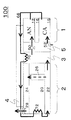
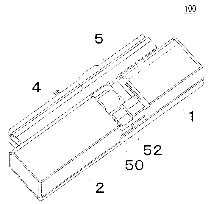
図1は本発明の燃料電池システム100の構成図である。図1において、この燃料電池システム100は、ダイレクトメタノール燃料電池の起電部1と、回収可能な燃料カートリッジ部2と、発電の化学反応に必要なメタノール水溶液を貯蔵しておくメタノール水溶液バッファタンク3と、このシステムを制御する制御装置などが収納された制御部4と、ポンプなどの補機類を収納した補機部5から構成されている。
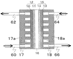
本燃料電池システム100の起電部1は図2に示すように、アノード集電体10とアノード触媒層11を含むアノード極12と、カソード集電体13およびカソード触媒層14を含むカソード極15と、上記アノード極12およびカソード極15の間に挟まれる電解質膜16から構成されている。
メタノール水溶液バッファタンク3から送液ポンプ50よりメタノール供給部60に供給されたメタノール水溶液は、アノードセパレータ17内のメタノール流路17aを流れる。メタノール流路17aはアノード集電体10に接しており、メタノール流路17aを流れるメタノール水溶液がアノード集電体10に含浸され、アノード触媒層11にメタノール水溶液が供給される。一部のメタノール水溶液はアノード触媒層11に含浸されず、メタノール排出部62より排出される。排出されるメタノール水溶液は発電反応により熱を持っており、さらに発電反応により生じた二酸化炭素も含まれている。
一方、送気ポンプ52より供給された酸化剤供給部64に供給された空気は、カソードセパレータ18内の酸化剤流路18aを流れ、カソード集電体13を通じてカソード触媒層14へ浸透する。浸透しなかった空気や反応しなかった空気は酸化剤排出部66より排出される。
電解質膜16としては高いプロトン導電性を持つナフィオン膜(デュポン社製)などが用いられ、アノード触媒層11には白金ルテニウム(PtRu)などが、カソード触媒層14にはPtなどが、一般的に触媒として用いられる。
このような構造を有するダイレクトメタノール燃料電池システム100において、アノード触媒層11にメタノール水溶液が供給されると、触媒反応によってプロトン(陽子)が発生する。
Embodiments of the present invention will be described below with reference to the drawings.
FIG. 1 is a configuration diagram of a
As shown in FIG. 2, the
The methanol aqueous solution supplied from the methanol aqueous
On the other hand, the air supplied to the
As the
In the direct methanol
上記のようなダイレクトメタノール燃料電池システムにおいて、起電部1のアノード極12へは、1mol/Lに調整されたメタノール水溶液が貯蔵されるメタノール水溶液バッファタンク部3から送液ポンプ50を介して1mol/Lメタノール水溶液が供給される。一方、カソード極15へは、外部より送気ポンプ52を介して空気が酸化剤として供給される。
そして、アノード極12においては、起電部1の発電反応により炭酸ガスが生じるほか、アノード極12での発電反応に使用されなかった未反応のメタノール、反応熱により気化したメタノールがアノード極12から排出され、排出パイプ68を介して気液分離器22へ送られる。また、カソード極15においては、起電部1の発電反応により生成水が生じるほか、カソード極15での発電反応に使用されなかった空気、反応熱による水蒸気、或いはアノード極12から電解質膜16を透過したメタノール、およびメタノールの気化物などがカソード極15から排出され、排出パイプ68にてアノード極12からの排出物質と合流して気液分離器22へ送られる。
排出パイプ68には気液分離器22へ送られる途中に、メタノール水溶液バッファタンク3との熱交換をおこなう第1熱交換部70と、高濃度メタノール水溶液タンク20との熱交換をおこなう第2熱交換部72とが設けられている。第1熱交換部70および第2熱交換部72は、効率よく熱が伝達されるような、熱容量が大きく、熱伝導率が高い材料で構成されている。
アノード極12から排出される炭酸ガス、未反応メタノール、気化したメタノール、および、カソード極15排出される空気、水、水蒸気、アノード極12から電解質膜16を透過したメタノールとその気化物は、発電反応による反応熱により高温になっている。この熱は、第1熱交換部70および第2熱交換部72によりメタノール水溶液バッファタンク3および高濃度メタノール水溶液タンク20へ供給され、アノード極12およびカソード極15からの上記排出物質は冷却される。
これにより、アノード極12から排出される気化したメタノール、および、カソード極15から排出される水蒸気、アノード極15から電解質膜16を透過したメタノールの気化物などの気体成分は冷却によって凝縮、液化し、それぞれ液体の水、液体のメタノールとなる。
気液分離器22には第1、第2熱交換部70、72にて十分に冷却された排出物質が流入し、液体成分はメタノール水溶液バッファタンク3へ、気体成分はガスパイプ26を通って有毒ガス回収部24へ移動するように接続されている。
本発明では、排出物質は起電部1と離れた位置に設けられている高濃度メタノール水溶液タンク20と第2熱交換部72において熱交換を行うため、気液分離器22に排出物質が流入する時点では十分に冷却されており、沸点の低いメタノールの回収を効率よく行うことが可能となる。更に、この気液分離を十分に行うために気液分離器22には気液分離膜を設けてもよい。
有毒ガス回収部24に送られる気体成分には、上記の空気、炭酸ガス以外に、液化しなかった気化メタノールおよび発電反応により生成したホルムアルデヒドや蟻酸などのガスが含まれている。特にメタノールやホルムアルデヒドは人体に有害であるため、それら有害物質を有毒ガス回収部24にて回収する。
有毒ガス回収部24にて、上記有害物質を回収し無害化されたガスはガス排出口28から外部へ排出される。高濃度メタノール水溶液タンク20は、第2熱交換部72によって温度が高くなっているので、高濃度メタノール水溶液タンク20に隣接する有毒ガス回収部24中の無害化されたガスは温められて上昇し、ガス排出口28からの排出が促進されることになる。これにより、有毒ガス回収部24から排出されるガスが滞留することなくなるため、有毒ガス回収部24での有毒ガスの無害化もスムーズに行われることになる。
なお、有毒ガス回収部24に有毒ガス吸着物質や気液分離器22に気液分離膜が装着された場合、これらは燃料電池システム100の運転の経過と共に消耗する物質であるので取り替える必要がある。よって、有毒ガス回収部24と気液分離器22は、同じく燃料電池システム100の運転の経過と共に消費される高濃度メタノール水溶液タンク20と一体化し、燃料カートリッジ部2として構成する。このような構成とすることにより、高濃度メタノール水溶液タンク20内のメタノール水溶液が消費され空になって新しい燃料カートリッジ部2と取り替えるときに、有毒ガス回収部24及び気液分離器22内の消耗する物質も同時に取り替えることができるようになる。
また、気液分離器22からメタノール水溶液バッファタンク3へ送られる水、未反応メタノールは、再び起電部1のアノード極12へ発電反応に必要な燃料として再利用される。気液分離器22から水、未反応メタノールがメタノール水溶液バッファタンク3に戻されることにより、メタノール水溶液バッファタンク3内のメタノール水溶液濃度は低下していく。起電部1に供給するメタノール水溶液の濃度が低下すると、起電部1内でメタノールが不足し起電力の低下につながる問題がある。従って、起電部1へ供給するメタノール水溶液濃度は0.5〜4mol/Lを維持するのが望ましく、メタノール水溶液バッファタンク3内のメタノール水溶液が所定の濃度まで低下すると、高濃度メタノール水溶液タンク20内より高濃度のメタノール水溶液がメタノール水溶液バッファタンク3へポンプ(図示せず)により適量供給され、メタノール水溶液バッファタンク3内のメタノール水溶液の濃度は0.5〜4mol/Lに維持できるように構成され、連続した安定的な発電が可能となる。また、高濃度メタノール水溶液タンク20内のメタノール水溶液の濃度は高いほど、長時間の発電が可能であり、高濃度メタノール水溶液タンク20内のメタノール水溶液の濃度は20mol/L以上が理想である。
In the direct methanol fuel cell system as described above, 1 mol of the methanol aqueous solution
In the
In the middle of being sent to the gas-
Carbon dioxide gas, unreacted methanol, vaporized methanol discharged from the
As a result, gaseous components such as vaporized methanol discharged from the
Exhaust substances sufficiently cooled by the first and second
In the present invention, since the exhaust material exchanges heat in the high-concentration methanol
The gas components sent to the toxic
The toxic
When a toxic gas adsorbing substance is attached to the toxic
Further, water and unreacted methanol sent from the gas-
高濃度メタノール水溶液タンク20内よりメタノール水溶液バッファタンク3へ供給する高濃度メタノール水溶液の送液を行うポンプの動作制御、およびその供給量を決定するためにメタノール水溶液バッファタンク3内のメタノール水溶液の濃度、水量、温度などを検知して、適当な供給量の決定などは制御部4が行う。
Operation control of a pump for feeding a high concentration methanol aqueous solution supplied from the high concentration methanol
1 起電部
2 燃料カートリッジ部
3 メタノール水溶液バッファタンク
4 制御部
5 補機部
10 アノード集電体
11 アノード触媒層
12 アノード極
13 カソード集電体
14 カソード触媒層
15 カソード極
16 電解質膜
17 アノードセパレータ
18 カソードセパレータ
20 高濃度メタノール水溶液タンク
22 気液分離器
24 有毒ガス回収部
26 ガスパイプ
28 ガス排出口
50 送液ポンプ
52 送気ポンプ
60 メタノール供給部
62 メタノール排出部
64 酸化剤供給部
66 酸化剤排出部
68 排出パイプ
70 第1熱交換部
72 第2熱交換部
100 燃料電池システム
DESCRIPTION OF
Claims (8)
少なくとも前記第1のタンクは交換可能に構成されることを特徴とする燃料電池システム。 A first tank for storing high-concentration fuel, a second tank for diluting the high-concentration fuel, fuel supplied in the second tank is supplied to the anode, and an oxidant is supplied to the cathode A fuel cell system comprising: a fuel cell that generates electricity by
The fuel cell system, wherein at least the first tank is configured to be replaceable.
少なくとも前記燃料電池のアノードより排出される排出物質と前記第1のタンクとを熱交換する第1の熱交換器を備えることを特徴とする燃料電池システム。 The fuel cell system according to claim 1, wherein
A fuel cell system comprising a first heat exchanger for exchanging heat between at least an exhaust material discharged from an anode of the fuel cell and the first tank.
前記排出物質と前記第2のタンクとを熱交換する第2の熱交換器を備え、
前記第1の熱交換器と前記第2の熱交換器とを直列に接続することを特徴とする燃料電池システム。 The fuel cell system according to claim 2, wherein
A second heat exchanger for exchanging heat between the exhaust material and the second tank;
The fuel cell system, wherein the first heat exchanger and the second heat exchanger are connected in series.
前記第1のタンクと一体に設けられ、少なくとも前記燃料電池のアノードより排出される排出物質の気相と液相とを分離する気液分離手段を備えることを特徴とする燃料電池システム。 The fuel cell system according to claim 1, wherein
A fuel cell system comprising gas-liquid separation means that is provided integrally with the first tank and separates at least a gas phase and a liquid phase of an exhaust material discharged from an anode of the fuel cell.
前記気液分離手段により分離された液相は、前記第2のタンクに導入されることを特徴とする燃料電池システム。 The fuel cell system according to claim 4, wherein
A fuel cell system, wherein the liquid phase separated by the gas-liquid separation means is introduced into the second tank.
前記第1のタンクと一体に設けられ、少なくとも前記燃料電池のアノードより排出される排出物質に含まれる有害物質を回収する有害物質回収手段を備えることを特徴とする燃料電池システム。 The fuel cell system according to claim 1, wherein
A fuel cell system, comprising: a harmful substance recovery means that is provided integrally with the first tank and recovers at least a harmful substance contained in an exhausted substance discharged from an anode of the fuel cell.
前記気液分離手段により分離された気相は、前記有害物質回収手段に導入されることを特徴とする燃料電池システム。 The fuel cell system according to claim 6, wherein
The gas phase separated by the gas-liquid separation means is introduced into the harmful substance recovery means.
前記第1のタンクと接して配置され、前記気液分離手段と前記有害物質回収手段とを接続する配管を備えることを特徴とする燃料電池システム。
The fuel cell system according to claim 7, wherein
A fuel cell system, comprising a pipe disposed in contact with the first tank and connecting the gas-liquid separation means and the harmful substance recovery means.
Priority Applications (1)
| Application Number | Priority Date | Filing Date | Title |
|---|---|---|---|
| JP2004105983A JP4030518B2 (en) | 2004-03-31 | 2004-03-31 | Direct methanol fuel cell system |
Applications Claiming Priority (1)
| Application Number | Priority Date | Filing Date | Title |
|---|---|---|---|
| JP2004105983A JP4030518B2 (en) | 2004-03-31 | 2004-03-31 | Direct methanol fuel cell system |
Publications (2)
| Publication Number | Publication Date |
|---|---|
| JP2005293974A true JP2005293974A (en) | 2005-10-20 |
| JP4030518B2 JP4030518B2 (en) | 2008-01-09 |
Family
ID=35326690
Family Applications (1)
| Application Number | Title | Priority Date | Filing Date |
|---|---|---|---|
| JP2004105983A Expired - Fee Related JP4030518B2 (en) | 2004-03-31 | 2004-03-31 | Direct methanol fuel cell system |
Country Status (1)
| Country | Link |
|---|---|
| JP (1) | JP4030518B2 (en) |
Cited By (3)
| Publication number | Priority date | Publication date | Assignee | Title |
|---|---|---|---|---|
| JP2008016441A (en) * | 2006-06-30 | 2008-01-24 | Syspotek Corp | Ultra small fuel cell system |
| US7824812B2 (en) | 2006-06-07 | 2010-11-02 | Panasonic Corporation | Fuel cell system |
| CN111864230A (en) * | 2020-07-02 | 2020-10-30 | 摩氢科技有限公司 | Heat exchange system of methanol reforming fuel cell and methanol reforming fuel cell system |
-
2004
- 2004-03-31 JP JP2004105983A patent/JP4030518B2/en not_active Expired - Fee Related
Cited By (3)
| Publication number | Priority date | Publication date | Assignee | Title |
|---|---|---|---|---|
| US7824812B2 (en) | 2006-06-07 | 2010-11-02 | Panasonic Corporation | Fuel cell system |
| JP2008016441A (en) * | 2006-06-30 | 2008-01-24 | Syspotek Corp | Ultra small fuel cell system |
| CN111864230A (en) * | 2020-07-02 | 2020-10-30 | 摩氢科技有限公司 | Heat exchange system of methanol reforming fuel cell and methanol reforming fuel cell system |
Also Published As
| Publication number | Publication date |
|---|---|
| JP4030518B2 (en) | 2008-01-09 |
Similar Documents
| Publication | Publication Date | Title |
|---|---|---|
| JP3742053B2 (en) | Fuel cell system | |
| JP5626718B2 (en) | Fuel cell system | |
| JP6529752B2 (en) | Fuel cell system | |
| KR100555264B1 (en) | Fuel cell system and fuel supply apparatus | |
| JP4624670B2 (en) | Integration of the functions of many components of a fuel cell power plant | |
| JP2009230926A (en) | Fuel cell system | |
| US20120264029A1 (en) | Fuel cell system | |
| JP2000164233A (en) | Solid polymer fuel cell power generation system | |
| KR102316740B1 (en) | Fuel cell system for a ship | |
| JP2007329002A (en) | Fuel cell system | |
| JP4030518B2 (en) | Direct methanol fuel cell system | |
| KR100859458B1 (en) | 스택 Stack structure of fuel cell using compound as fuel | |
| JP2013097870A (en) | Alkaline fuel cell system | |
| JP2000260455A (en) | Deterioration restoring process for fuel cell | |
| JP2005100886A (en) | Fuel cell system and fuel supply method to fuel cell | |
| JP2008516401A (en) | Single pass high fuel concentration mixed reactant fuel cell power generation apparatus and method | |
| JP3993177B2 (en) | Fuel cell system | |
| KR100448692B1 (en) | Fuel feed system for fuel cell | |
| JP3561659B2 (en) | Fuel cell system | |
| JP2004281332A (en) | Power supply device and equipment that requires power using it | |
| KR102316741B1 (en) | Fuel cell system for a ship | |
| JP2005032600A (en) | Gas-liquid separation system and gas-liquid separation method | |
| KR100533008B1 (en) | Fuel cell system having water trap apparatus | |
| JP2008186800A (en) | Gas-liquid separator and fuel cell device equipped with the same | |
| KR100539753B1 (en) | Water supply system of fuel cell system |
Legal Events
| Date | Code | Title | Description |
|---|---|---|---|
| RD01 | Notification of change of attorney |
Free format text: JAPANESE INTERMEDIATE CODE: A7421 Effective date: 20051227 |
|
| A977 | Report on retrieval |
Free format text: JAPANESE INTERMEDIATE CODE: A971007 Effective date: 20070628 |
|
| A131 | Notification of reasons for refusal |
Free format text: JAPANESE INTERMEDIATE CODE: A131 Effective date: 20070703 |
|
| A521 | Written amendment |
Free format text: JAPANESE INTERMEDIATE CODE: A523 Effective date: 20070822 |
|
| TRDD | Decision of grant or rejection written | ||
| A01 | Written decision to grant a patent or to grant a registration (utility model) |
Free format text: JAPANESE INTERMEDIATE CODE: A01 Effective date: 20070918 |
|
| A61 | First payment of annual fees (during grant procedure) |
Free format text: JAPANESE INTERMEDIATE CODE: A61 Effective date: 20071016 |
|
| FPAY | Renewal fee payment (event date is renewal date of database) |
Free format text: PAYMENT UNTIL: 20101026 Year of fee payment: 3 |
|
| FPAY | Renewal fee payment (event date is renewal date of database) |
Free format text: PAYMENT UNTIL: 20101026 Year of fee payment: 3 |
|
| FPAY | Renewal fee payment (event date is renewal date of database) |
Free format text: PAYMENT UNTIL: 20111026 Year of fee payment: 4 |
|
| FPAY | Renewal fee payment (event date is renewal date of database) |
Free format text: PAYMENT UNTIL: 20111026 Year of fee payment: 4 |
|
| FPAY | Renewal fee payment (event date is renewal date of database) |
Free format text: PAYMENT UNTIL: 20121026 Year of fee payment: 5 |
|
| FPAY | Renewal fee payment (event date is renewal date of database) |
Free format text: PAYMENT UNTIL: 20121026 Year of fee payment: 5 |
|
| FPAY | Renewal fee payment (event date is renewal date of database) |
Free format text: PAYMENT UNTIL: 20131026 Year of fee payment: 6 |
|
| LAPS | Cancellation because of no payment of annual fees |