JP2005293960A - Negative electrode for lithium ion secondary battery and lithium ion secondary battery - Google Patents
Negative electrode for lithium ion secondary battery and lithium ion secondary battery Download PDFInfo
- Publication number
- JP2005293960A JP2005293960A JP2004105610A JP2004105610A JP2005293960A JP 2005293960 A JP2005293960 A JP 2005293960A JP 2004105610 A JP2004105610 A JP 2004105610A JP 2004105610 A JP2004105610 A JP 2004105610A JP 2005293960 A JP2005293960 A JP 2005293960A
- Authority
- JP
- Japan
- Prior art keywords
- negative electrode
- ion secondary
- lithium ion
- secondary battery
- layer
- Prior art date
- Legal status (The legal status is an assumption and is not a legal conclusion. Google has not performed a legal analysis and makes no representation as to the accuracy of the status listed.)
- Pending
Links
Images

Classifications
-
- Y—GENERAL TAGGING OF NEW TECHNOLOGICAL DEVELOPMENTS; GENERAL TAGGING OF CROSS-SECTIONAL TECHNOLOGIES SPANNING OVER SEVERAL SECTIONS OF THE IPC; TECHNICAL SUBJECTS COVERED BY FORMER USPC CROSS-REFERENCE ART COLLECTIONS [XRACs] AND DIGESTS
- Y02—TECHNOLOGIES OR APPLICATIONS FOR MITIGATION OR ADAPTATION AGAINST CLIMATE CHANGE
- Y02E—REDUCTION OF GREENHOUSE GAS [GHG] EMISSIONS, RELATED TO ENERGY GENERATION, TRANSMISSION OR DISTRIBUTION
- Y02E60/00—Enabling technologies; Technologies with a potential or indirect contribution to GHG emissions mitigation
- Y02E60/10—Energy storage using batteries
Landscapes
- Secondary Cells (AREA)
- Battery Electrode And Active Subsutance (AREA)
Abstract
【課題】負極活物質として炭素を用いた場合よりも放電容量が高く、かつサイクル特性に優れたリチウムイオン二次電池の提供と、そのための負極の提供。
【解決手段】集電体に、リチウムイオンを吸蔵・脱離する金属の薄層を面積率5〜90%で有し、該薄層の上に、炭素材料の層を有するリチウムイオン二次電池用負極、および該負極を用いたリチウムイオン二次電池。
【選択図】図2Provided is a lithium ion secondary battery having a higher discharge capacity and excellent cycle characteristics than when carbon is used as a negative electrode active material, and a negative electrode therefor.
A lithium ion secondary battery having a current collector with a thin metal layer that absorbs and desorbs lithium ions at an area ratio of 5 to 90%, and a carbon material layer on the thin layer. Negative electrode, and a lithium ion secondary battery using the negative electrode.
[Selection] Figure 2
Description
本発明は、リチウムイオン二次電池用負極、該負極を用いた放電容量が大きいリチウムイオン二次電池に関する。 The present invention relates to a negative electrode for a lithium ion secondary battery and a lithium ion secondary battery having a large discharge capacity using the negative electrode.
リチウムイオン二次電池は作動電圧が高いこと、電池容量が大きいことおよびサイクル寿命が長いなどの優れた特徴を有し、かつ環境汚染が少ないことから、従来主流であったニッケル・カドミウム電池やニッケル水素電池に代わって広範囲で用いられている。リチウムイオン二次電池が実用可能となったのは、負極材料として安全性に問題があったリチウム金属に代わり、リチウムイオンを層間挿入した炭素材料が安定した活物質となり得ることが発見され、リチウムイオン二次電池の実用化と性能向上に果たす炭素材料の役割が認識されたことに起因する。 Lithium-ion secondary batteries have excellent features such as high operating voltage, large battery capacity, long cycle life, and low environmental pollution. Therefore, conventional nickel-cadmium batteries and nickel It is widely used in place of hydrogen batteries. Lithium ion secondary batteries have become practical because it was discovered that carbon materials with intercalated lithium ions could be a stable active material instead of lithium metal, which had a safety problem as a negative electrode material. This is due to the recognition of the role of carbon materials in the practical application and performance improvement of ion secondary batteries.
近年の携帯電話やノートパソコンなどの携帯電子機器の高性能・高機能化に伴い消費電力が増加し、リチウムイオン二次電池のさらなる高容量化が求められている。リチウムイオン二次電池の容量は、特に負極用炭素材料の質量当りの放電容量が大きな支配要因であるが、質量当りの放電容量は炭素材料の中では高純度の天然黒鉛の理論容量372mAh/gが限界である。そのため、炭素に代えて、単位質量当りの放電容量が高いケイ素、錫などを用いることが検討されている。例えば、特許文献1には、集電体の上に、ケイ素、ゲルマニウムなどの第一活物質層を形成し、さらにその上に炭素の第二活物質層を形成した電極が提案されている。しかし、第一活物質層は集電体の全体を覆っており、これらの材料は充電時の膨張率が大きいため、炭素の第二活物質層との剥離が生じ、充分な電流を供給できないという問題があった。例えば、ケイ素では300%もの体積膨張をするため、負極が繰り返しの充放電により崩壊し、放電容量が劣化するという問題があった。
また、集電体の上に、錫ーニッケル合金、リチウムーアルミニウム合金などの薄膜を形成し、さらにその上に炭素材料の層を形成した二次電池用電極が提案されている(特許文献2)。これには、炭素材料の層への電流供給が不充分であるという問題がある。
Further, an electrode for a secondary battery is proposed in which a thin film such as a tin-nickel alloy or a lithium-aluminum alloy is formed on a current collector, and a carbon material layer is further formed thereon (Patent Document 2). . This has the problem that the current supply to the layer of carbon material is insufficient.
本発明は、負極活物質としての炭素より単位質量当たりの放電容量が大きいが、膨張率が大きいケイ素、錫などの金属や合金を用いるにも拘わらず、集電体の表面に所定の面積率の合金の薄膜が形成されており、炭素材料の層に直接電流が供給されるため、リチウムイオンの充電時における、負極合剤層中のケイ素、錫などの金属や合金の膨張を吸収でき、放電容量が高く、かつサイクル特性に優れたリチウムイオン二次電池を提供すること、および、そのための負極を提供することが目的である。 The present invention has a discharge capacity per unit mass larger than that of carbon as a negative electrode active material, but a predetermined area ratio is applied to the surface of the current collector in spite of using a metal or an alloy such as silicon or tin having a large expansion coefficient. Since a thin film of the alloy is formed and a current is directly supplied to the carbon material layer, it can absorb expansion of metals and alloys such as silicon and tin in the negative electrode mixture layer during lithium ion charging, It is an object to provide a lithium ion secondary battery having a high discharge capacity and excellent cycle characteristics, and to provide a negative electrode therefor.
本発明は、集電体の表面に、リチウムイオンを吸蔵・脱離する金属の薄層を、面積率5〜90%で有し、さらにその上に炭素材料の層を有することを特徴とするリチウムイオン二次電池用負極である。 The present invention is characterized in that a thin layer of metal that absorbs and desorbs lithium ions is provided on the surface of the current collector at an area ratio of 5 to 90%, and further a carbon material layer is provided thereon. It is a negative electrode for lithium ion secondary batteries.
本発明のリチウムイオン二次電池用負極において、前記金属の薄層を形成する金属はケイ素、錫、アンチモン、ニオブまたはアルミニウムの単体または合金であることが好ましい。 In the negative electrode for a lithium ion secondary battery of the present invention, the metal forming the thin metal layer is preferably silicon, tin, antimony, niobium or aluminum alone or an alloy.
本発明のリチウムイオン二次電池用負極において、前記金属の薄層の層厚は10μm以下であることが好ましい。 In the negative electrode for a lithium ion secondary battery of the present invention, the thickness of the thin metal layer is preferably 10 μm or less.
本発明のリチウムイオン二次電池用負極において、前記集電体は銅、ニッケル、ステンレスまたは鉄であることが好ましい。 In the negative electrode for a lithium ion secondary battery according to the present invention, the current collector is preferably copper, nickel, stainless steel, or iron.
本発明は、前記のいずれかのリチウムイオン二次電池用負極を用いたリチウムイオン二次電池である。 The present invention is a lithium ion secondary battery using any one of the negative electrodes for lithium ion secondary batteries described above.
本発明のリチウムイオン二次電池用負極は、リチウムイオン吸蔵の際に膨張が大きいケイ素や錫などの金属が、集電体に接しているため、この膨張を吸収することができる。しかも該金属が粒子状で分散しているため、炭素材料の層への導電性も良好となる。その結果、本発明のリチウムイオン二次電池用負極を用いてリチウムイオン二次電池を作製したときに、高い放電容量が得られ、サイクル特性にも優れる。 The negative electrode for a lithium ion secondary battery of the present invention can absorb this expansion because a metal such as silicon or tin, which has a large expansion during lithium ion storage, is in contact with the current collector. Moreover, since the metal is dispersed in the form of particles, the conductivity to the carbon material layer is also good. As a result, when a lithium ion secondary battery is produced using the negative electrode for a lithium ion secondary battery of the present invention, a high discharge capacity is obtained and the cycle characteristics are excellent.
以下、本発明を具体的に説明する。
本発明は、集電体の表面に、リチウムイオンを吸蔵・脱離する金属(後述するように、合金を含む)の薄層を、面積率5〜90%で有し、さらにその上に炭素材料の層を有するリチウムイオン二次電池用負極である。
The present invention will be specifically described below.
The present invention has a thin layer of metal (including an alloy as will be described later) with an area ratio of 5 to 90% on the surface of the current collector, and further has carbon on it. It is a negative electrode for lithium ion secondary batteries which has a layer of material.
(集電体)
負極に用いる集電体の材質は、銅、ステンレス、ニッケル、鉄などの金属であり、特に好ましいのは銅である。集電体の形状は、特に限定されないが、箔状、またはメッシュ、エキスパンドメタルなどの網状のものなどが用いられる。集電体の厚さは、箔状の場合、5〜20μm、特に5〜15μmであることが好ましい。集電体の大きさは、リチウムイオン二次電池の大きさにより決められる。
(Current collector)
The material of the current collector used for the negative electrode is a metal such as copper, stainless steel, nickel, or iron, and copper is particularly preferable. The shape of the current collector is not particularly limited, but a foil or a net-like material such as a mesh or expanded metal is used. The thickness of the current collector is preferably 5 to 20 μm, particularly 5 to 15 μm in the case of a foil. The size of the current collector is determined by the size of the lithium ion secondary battery.
(金属の薄層)
負極に用いる集電体の表面に存する金属の薄層は、負極の放電容量の増大に有効に作用する。該金属の薄層は、集電体の表面の全面ではなく、一部分に形成される。それは、面積率として5〜90%、好ましくは10〜80%、より好ましくは20〜70%である。5%未満であると、該金属の薄層のリチウムイオンによる金属の負極としての膨張を吸収することができない。90%超であると、負極としての導電性に劣る。該金属の薄層の面積率は、用いた金属の特性X線のマッピング像を10視野観察した平均値である。
また、金属は、粒子状に分散するか、粒子同士が融合しているので、負極としての導電性に優れ、高い放電容量が得られる。
金属の薄層の層厚は10μm以下であることが好ましく、0.5〜8μmであることがより好ましい。10μmを超えると、金属の薄層の膨張収縮による崩壊が生じる虞がある。該層厚はマイクロメーターにより10箇所の層厚を測定し、算術平均した値である。
(Thin metal layer)
The thin metal layer present on the surface of the current collector used for the negative electrode effectively works to increase the discharge capacity of the negative electrode. The thin metal layer is formed not on the entire surface of the current collector but on a part thereof. The area ratio is 5 to 90%, preferably 10 to 80%, more preferably 20 to 70%. If it is less than 5%, the expansion of the metal thin layer as a negative electrode caused by lithium ions cannot be absorbed. If it exceeds 90%, the conductivity as the negative electrode is poor. The area ratio of the thin metal layer is an average value obtained by observing 10 fields of the mapping image of the characteristic X-ray of the metal used.
In addition, since the metal is dispersed in the form of particles or the particles are fused, the metal has excellent conductivity as a negative electrode, and a high discharge capacity can be obtained.
The thickness of the metal thin layer is preferably 10 μm or less, and more preferably 0.5 to 8 μm. If it exceeds 10 μm, the metal thin layer may collapse due to expansion and contraction. The layer thickness is a value obtained by measuring the layer thickness at 10 locations with a micrometer and calculating the arithmetic average.
該金属の薄層は、金属または合金の融液を集電体に塗布する方法、金属または合金をめっきする方法などにより一旦、金属または合金の薄層を形成した後、エッチングにより一部の薄層を除去する方法、金属をスパッタリングや真空蒸着で集電体に付着させ、薄層を形成する際に、集電体表面の一部をマスクする方法などにより形成される。一旦形成された金属の薄層を平滑にするために、ガスブロー、熱処理、圧延などの処理を施してもよい。 The thin metal layer is formed by forming a thin metal or alloy layer by a method of applying a melt of a metal or an alloy to a current collector, a method of plating a metal or an alloy, or the like, followed by etching. It is formed by a method of removing a layer, a method of attaching a metal to a current collector by sputtering or vacuum vapor deposition, and masking a part of the surface of the current collector when forming a thin layer. In order to smooth the thin metal layer once formed, treatment such as gas blowing, heat treatment, and rolling may be performed.
該金属または合金は、リチウムイオンの吸蔵・脱離可能な金属または合金であれば、特に限定されないが、ケイ素、錫、アンチモン、ニオブ、アルミニウムなどの金属の単体または合金であることが好ましい。特に好ましいのは、ケイ素または錫の単体またはケイ素または錫を含む合金である。金属または合金の薄層における形状は特に限定されないが、集電体の表面に対し垂直方向から観察し、粒子状に分布していることが好ましい。粒子状に分布する該金属または合金の粒径は1nm〜100μm、好ましくは10nm〜50μm、より好ましくは0.1〜10μmである。該粒径は走査型電子顕微鏡で粒子100個の最大径を測定し、算術平均した値である。 The metal or alloy is not particularly limited as long as it is a metal or alloy capable of occluding and releasing lithium ions, but is preferably a simple substance or an alloy of metal such as silicon, tin, antimony, niobium, and aluminum. Particularly preferred are silicon or tin alone or an alloy containing silicon or tin. Although the shape in the thin layer of a metal or an alloy is not specifically limited, It is preferable to observe from the orthogonal | vertical direction with respect to the surface of a collector, and to distribute in a particle form. The particle size of the metal or alloy distributed in the form of particles is 1 nm to 100 μm, preferably 10 nm to 50 μm, more preferably 0.1 to 10 μm. The particle diameter is a value obtained by measuring the maximum diameter of 100 particles with a scanning electron microscope and arithmetically averaging them.
(炭素材料層)
本発明の負極は、前記金属の薄層の上に炭素材料層を有している。炭素材料層は、リチウムイオンを吸臓して膨張する金属の薄層の崩壊を防止する作用をする。その結果、リチウムイオン二次電池のサイクル特性を向上させることができる。
炭素材料層は、集電体表面の金属の薄層の上、および該金属の薄層がない部分、すなわち、集電体表面上に形成される。いわば、炭素材料が金属の間に、集電体表面にまで、楔のように食い込んだ構造をしているので、金属の薄層の崩壊防止がより強化される。ここで、炭素材料層の付着量は5〜40mg/cm2、特に10〜20mg/cm2とすることが好ましい。この範囲とすることで、金属の薄層の膨張を吸収でき、サイクル特性を向上させることができる。また、この付着量は、炭素材料層を形成させる前後で質量を測定して、形成前後の質量差により求めることができる。
(Carbon material layer)
The negative electrode of the present invention has a carbon material layer on the thin metal layer. The carbon material layer acts to prevent the collapse of the thin metal layer that absorbs lithium ions and expands. As a result, the cycle characteristics of the lithium ion secondary battery can be improved.
The carbon material layer is formed on the thin metal layer on the surface of the current collector and on the portion where the thin metal layer is not present, that is, on the current collector surface. In other words, since the carbon material has a structure in which the carbon material is intruded to the surface of the current collector between the metals, the prevention of the collapse of the thin metal layer is further enhanced. Here, the adhesion amount of the carbon material layer is preferably 5 to 40 mg / cm 2 , particularly preferably 10 to 20 mg / cm 2 . By setting it as this range, the expansion of the thin metal layer can be absorbed, and the cycle characteristics can be improved. Moreover, this adhesion amount can be calculated | required by the mass difference before and behind formation, measuring mass before and after forming a carbon material layer.
炭素材料層の形成は、炭素材料の性能を充分に引出し、かつ炭素材料粉末に対する成形性が高く、化学的、電気化学的に安定な負極を得ることができる方法であれば、特に制限されない。例えば、天然黒鉛複合体、炭素繊維黒鉛化物、メソカーボン小球体黒鉛化物などの炭素材料を分級などによって適当な粒径に調整し、有機溶媒の存在で、結合剤と混合することによって負極合剤ペーストを調製し、該ペーストを集電体の片面あるいは両面の前記金属の薄層の上に塗布して炭素材料層を形成する。 The formation of the carbon material layer is not particularly limited as long as it is a method capable of sufficiently drawing out the performance of the carbon material, having high moldability for the carbon material powder, and obtaining a chemically and electrochemically stable negative electrode. For example, negative electrode mixture by adjusting carbon materials such as natural graphite composite, carbon fiber graphitized material, mesocarbon microsphere graphitized material to appropriate particle size by classification, etc., and mixing with binder in the presence of organic solvent A paste is prepared, and the paste is applied on the thin metal layer on one or both sides of the current collector to form a carbon material layer.
結合剤としては、電解質に対して化学的安定性、電気化学的安定性を有するものを用いることが好ましく、例えば、ポリフッ化ビニリデン、ポリテトラフルオロエチレンなどのフッ素系樹脂、ポリエチレン、ポリビニルアルコール、カルボキシメチルセルロース、スチレンブタジエンラバーなどが用いられる。これらを併用することもできる。ポリフッ化ビニリデンなどの有機溶媒系結合剤を用いることが好ましい。結合剤は、通常、負極合剤ペースト全量中0.5〜20質量%の量で用いることが好ましい。
なお、本発明においては、有機溶媒に溶解または分散する有機溶媒系結合剤はもちろんのこと、水溶性および/または水分散性の水系結合剤を用いても優れた充放電特性を有する負極を得ることができる。
As the binder, those having chemical stability and electrochemical stability with respect to the electrolyte are preferably used. For example, fluorine resins such as polyvinylidene fluoride and polytetrafluoroethylene, polyethylene, polyvinyl alcohol, carboxy Methyl cellulose, styrene butadiene rubber or the like is used. These can also be used together. It is preferable to use an organic solvent binder such as polyvinylidene fluoride. In general, the binder is preferably used in an amount of 0.5 to 20% by mass in the total amount of the negative electrode mixture paste.
In the present invention, an anode having excellent charge / discharge characteristics is obtained not only with an organic solvent-based binder dissolved or dispersed in an organic solvent, but also with a water-soluble and / or water-dispersible aqueous binder. be able to.
(負極)
より具体的な負極の作製は、例えば、炭素材料と、ポリテトラフルオロエチレンなどのフッ素系樹脂粉末とを、イソプロピルアルコールなどの溶媒中で混合・混練して、ペーストを得、これを集電体に塗布する方法である。また高結晶性炭素材料と、ポリフッ化ビニリデン等のフッ素系樹脂および/またはカルボキシメチルセルロース、スチレンブタジエンラバーなどを、N-メチルピロリドン、ジメチルホルムアミド、水、アルコールなどの溶媒と混合してスラリーとした後、塗布することもできる。
ペーストは、公知の攪拌機、混合機、混練機、ニーダーなどを用いて攪拌することにより調製することができる。
前記負極合剤ペーストを前記金属の薄層上に塗布、乾燥すれば、炭素材料層が均一かつ強固に、金属の薄層を有する集電体に接着される。炭素材料と、ポリエチレン、ポリビニルアルコールなどの樹脂粉末とを乾式混合し、金型内でホットプレス成形して炭素材料層を形成することもできる。炭素材料層を形成した後、プレス加圧などの圧着を行うと、炭素材料層と金属の薄層を有する集電体との接着強度をさらに高めた負極が作製できる。
(Negative electrode)
More specifically, for example, a negative electrode is produced by mixing and kneading a carbon material and a fluororesin powder such as polytetrafluoroethylene in a solvent such as isopropyl alcohol to obtain a paste, which is used as a current collector. It is the method of apply | coating to. In addition, after mixing a highly crystalline carbon material and a fluororesin such as polyvinylidene fluoride and / or carboxymethylcellulose, styrene butadiene rubber, etc. with a solvent such as N-methylpyrrolidone, dimethylformamide, water, alcohol, etc., to make a slurry It can also be applied.
The paste can be prepared by stirring using a known stirrer, mixer, kneader, kneader or the like.
When the negative electrode mixture paste is applied onto the thin metal layer and dried, the carbon material layer is uniformly and firmly adhered to the current collector having the thin metal layer. The carbon material layer can also be formed by dry-mixing a carbon material and resin powder such as polyethylene and polyvinyl alcohol and hot pressing in a mold. When the carbon material layer is formed and then subjected to pressure bonding such as press-pressing, a negative electrode in which the adhesion strength between the carbon material layer and the current collector having a thin metal layer is further increased can be manufactured.
(リチウムイオン二次電池)
リチウムイオン二次電池は、本質的に、充放電時にはリチウムイオンが負極中に吸蔵され、放電時には負極から脱離する電池機構である。リチウムイオン二次電池は、通常、負極、正極および非水電解質を主たる電池構成要素とする。本発明のリチウムイオン二次電池は、負極として集電体の上に前記の金属の薄層と炭素材料層を有すること以外は特に限定されず、他の電池構成要素については一般的なリチウムイオン二次電池の要素に準ずる。
(Lithium ion secondary battery)
The lithium ion secondary battery is essentially a battery mechanism in which lithium ions are occluded in the negative electrode during charge / discharge and are detached from the negative electrode during discharge. A lithium ion secondary battery usually includes a negative electrode, a positive electrode, and a nonaqueous electrolyte as main battery components. The lithium ion secondary battery of the present invention is not particularly limited except that it has a thin metal layer and a carbon material layer on a current collector as a negative electrode, and other battery components are general lithium ions. Conforms to secondary battery elements.
正極の材料(正極活物質)としては、充分量のリチウムを吸蔵・脱離しうるものを選択するのが好ましい。そのような正極活物質としては、リチウム含有遷移金属酸化物、遷移金属カルコゲン化物、バナジウム酸化物(V2O5、V6O13、V2O4、V3O8など)およびLi化合物などのリチウム含有化合物、一般式MXMo6S8-Y(式中Xは0≦X≦4、Yは0≦Y≦1の範囲の数値であり、Mは遷移金属などの金属を表す)で表されるシェブレル相化合物、活性炭、活性炭素繊維などを用いることができる。 As the positive electrode material (positive electrode active material), it is preferable to select a material capable of inserting and extracting a sufficient amount of lithium. Examples of such positive electrode active materials include lithium-containing transition metal oxides, transition metal chalcogenides, vanadium oxides (V 2 O 5 , V 6 O 13 , V 2 O 4 , V 3 O 8, etc.) and Li compounds. Lithium-containing compound of general formula M X Mo 6 S 8-Y (where X is a numerical value in the range of 0 ≦ X ≦ 4, Y is 0 ≦ Y ≦ 1, and M represents a metal such as a transition metal) A chevrel phase compound represented by the formula, activated carbon, activated carbon fiber and the like can be used.
前記リチウム含有遷移金属酸化物は、リチウムと遷移金属との複合酸化物であり、リチウムと2種類以上の遷移金属を固溶したものであってもよい。リチウム含有遷移金属酸化物は、具体的には、LiM(1)1-XM(2)XO2(式中Xは0≦X≦1の範囲の数値であり、M(1)、M(2)は少なくとも一種類の遷移金属を表す)またはLIM(1)2-YM(2)YO4(式中Yは0≦Y≦1の範囲の数値であり、M(1)、M(2)は少なくとも一種の遷移金属元素を表す)で示される。
前記において、Mで示される遷移金属元素としては、Co、Ni、Mn、Cr、Ti、V、Fe、Zn、Al、In、Snなどが挙げられ、好ましくはCo、Fe、Mn、Ti、Cr、V、Alが挙げられる。
リチウム含有遷移金属酸化物としては、より具体的に、LiCoO2、LiXNiYM1-YO2(MはNiを除く遷移金属元素、好ましくはCo、Fe、Mn、Ti、Cr、V、Alから選ばれる少なくとも一種、0.05≦X≦1.10、0.5≦Y≦1.0である)で示されるリチウム複合酸化物、LiNiO2、LiMnO2、LiMn2O4などが挙げられる。
The lithium-containing transition metal oxide is a composite oxide of lithium and a transition metal, and may be a solid solution of lithium and two or more transition metals. Specifically, the lithium-containing transition metal oxide is LiM (1) 1-X M (2) X O 2 (where X is a numerical value in the range of 0 ≦ X ≦ 1, M (1), M (2) represents at least one transition metal) or LIM (1) 2-Y M (2) Y O 4 (where Y is a numerical value in the
In the above, the transition metal element represented by M includes Co, Ni, Mn, Cr, Ti, V, Fe, Zn, Al, In, Sn, etc., preferably Co, Fe, Mn, Ti, Cr , V, and Al.
More specifically, as the lithium-containing transition metal oxide, LiCoO 2 , Li X Ni Y M 1-Y O 2 (M is a transition metal element excluding Ni, preferably Co, Fe, Mn, Ti, Cr, V , At least one selected from Al, 0.05 ≦ X ≦ 1.10, 0.5 ≦ Y ≦ 1.0), LiNiO 2 , LiMnO 2 , LiMn 2 O 4 and the like.
前記のようなリチウム含有遷移金属酸化物は、例えば、Li、遷移金属の酸化物または塩類を出発原料とし、これら出発原料を組成に応じて混合し、酸素存在雰囲気下600〜1000℃の温度範囲で焼成することにより得ることができる。なお、出発原料は酸化物または塩類に限定されず、水酸化物などからも合成可能である。
本発明においては、正極活物質として、前記化合物を単独で使用しても2種類以上併用してもよい。また、炭酸リチウムなどの炭素塩や、従来公知の導電剤や結着剤などの各種添加剤を適宜添加することができる。
このような正極材料によって正極を形成するには、例えば、正極材料と結合剤および電極に導電性を付与するための導電剤よりなる正極合剤を集電体の両面に塗布することで正極合剤層を形成する。結合剤としては、負極で例示したものがいずれも使用可能である。導電剤としては、例えば、黒鉛質粒子が用いられる。
The lithium-containing transition metal oxide as described above includes, for example, Li, transition metal oxides or salts as starting materials, these starting materials are mixed according to the composition, and a temperature range of 600 to 1000 ° C. in an oxygen-existing atmosphere. It can obtain by baking with. Note that the starting materials are not limited to oxides or salts, and can be synthesized from hydroxides or the like.
In the present invention, the positive electrode active material may be used alone or in combination of two or more. Moreover, carbon salt, such as lithium carbonate, and various additives, such as a conventionally well-known electrically conductive agent and a binder, can be added suitably.
In order to form a positive electrode with such a positive electrode material, for example, a positive electrode mixture comprising a positive electrode material, a binder, and a conductive agent for imparting conductivity to the electrode is applied to both sides of the current collector. An agent layer is formed. As the binder, any of those exemplified for the negative electrode can be used. As the conductive agent, for example, graphite particles are used.
集電体の形状は特に限定されず、箔状、あるいはメッシュ、エキスパンドメタルなどの網状などのものが用いられる。例えば、集電体としては、アルミニウム、ステンレス、ニッケルなどを挙げることができる。その厚さとしては、10〜40μmのものが好適である。
また正極の場合も負極と同様に、正極合剤を溶剤中に分散させることでペースト状にし、このペースト状の正極合剤を集電体に塗布、乾燥することによって正極合剤層を形成してもよく、正極合剤層を形成した後、さらにプレス加圧などの圧着を行ってもよい。これにより正極合剤層が均一かつ強固に集電体に接着される。
The shape of the current collector is not particularly limited, and a foil shape or a net shape such as a mesh or expanded metal is used. For example, examples of the current collector include aluminum, stainless steel, and nickel. The thickness is preferably 10 to 40 μm.
Also in the case of the positive electrode, like the negative electrode, the positive electrode mixture is dispersed in a solvent to form a paste, and the paste-like positive electrode mixture is applied to a current collector and dried to form a positive electrode mixture layer. Alternatively, after the positive electrode mixture layer is formed, pressure bonding such as press pressing may be further performed. Thereby, the positive electrode mixture layer is uniformly and firmly bonded to the current collector.
本発明に用いられる電解質としては通常の非水電解液に使用されている電解質塩を用いることができ、例えばLiPF6、LiBF4、LiAsF6、LiClO4、LiB(C6H5)、LiCl、LiBr、LiCF3SO3、LiCH3SO3、LiN(CF3SO2)、LiC(CF3SO2)3、LiN(CF3CH2OSO2)2、LiN(HCF2CF2CH2OSO2)2、LiN[(CF3)2CHOSO2 ]2、LiB[C6H3(CF3)2]4、LiAlCl4、LiSiF6などのリチウム塩を用いることができる。特に、LiPF6、LiBrF4が酸化安定性の点から好ましく用いられる。
電解液中の電解質濃度は、0.1〜5mol/Lが好ましく、0.5〜3.0mol/Lがより好ましい。
前記非水電解質は、液系の非水電解液としてもよいし、固体電解質あるいはゲル電解質などの高分子電解質としてもよい。前者の場合、非水系電解質電池は、いわゆるリチウムイオン電池として構成され、後者の場合、非水電解質電池は、高分子固体電解質電池、高分子ゲル電解質電池などの高分子電解質電池として構成される。
As the electrolyte used for the present invention can be used an electrolyte salt used in the conventional non-aqueous electrolyte solution, for example LiPF 6, LiBF 4, LiAsF 6 , LiClO 4, LiB (C 6 H 5), LiCl, LiBr, LiCF 3 SO 3 , LiCH 3 SO 3 , LiN (CF 3 SO 2 ), LiC (CF 3 SO 2 ) 3 , LiN (CF 3 CH 2 OSO 2 ) 2 , LiN (HCF 2 CF 2 CH 2 OSO 2 ) 2 , LiN [(CF 3 ) 2 CHOSO 2 ] 2 , LiB [C 6 H 3 (CF 3 ) 2 ] 4 , LiAlCl 4 , LiSiF 6 and other lithium salts can be used. In particular, LiPF6 and LiBrF4 are preferably used from the viewpoint of oxidation stability.
0.1-5 mol / L is preferable and, as for the electrolyte concentration in electrolyte solution, 0.5-3.0 mol / L is more preferable.
The non-aqueous electrolyte may be a liquid non-aqueous electrolyte or a polymer electrolyte such as a solid electrolyte or a gel electrolyte. In the former case, the non-aqueous electrolyte battery is configured as a so-called lithium ion battery, and in the latter case, the non-aqueous electrolyte battery is configured as a polymer electrolyte battery such as a polymer solid electrolyte battery or a polymer gel electrolyte battery.
液系の非水電解液とする場合には、溶媒として、エチレカーボネート、プロピレンカーボネート、ジエチルカーボネート、ジメチルカーボネート、1,1-または1,2-ジメトキシエタン、1,2-ジエトキシエタン、テトラヒドロフラン、2-メチルタトラヒドロフラン、γ-ブチルラクトン、1,3-ジオキソラン、4-メチル-1,3-ジオキソラン、アニソール、ジエチルエーテル、スルホラン、メチルスルホラン、アセトニトリル、クロロニトリル、プロピオニトリル、ホウ酸トリメチル、ケイ酸テトラメチル、ニトロメタン、ジメチルホルムアミド、N-メチルピロリドン、酢酸エチル、テトラヒドロチオフェン、ジメチルスルホキシド、3-メチル-2-オキサゾリドン、エチレングリコール、ジメチルサルファイト等の非プロトン性有機溶媒を用いることができる。 In the case of a liquid nonaqueous electrolyte, the solvent is ethylene carbonate, propylene carbonate, diethyl carbonate, dimethyl carbonate, 1,1- or 1,2-dimethoxyethane, 1,2-diethoxyethane, tetrahydrofuran, 2-methyltatrahydrofuran, γ-butyllactone, 1,3-dioxolane, 4-methyl-1,3-dioxolane, anisole, diethyl ether, sulfolane, methylsulfolane, acetonitrile, chloronitrile, propionitrile, trimethylborate Aprotic organic solvents such as tetramethyl silicate, nitromethane, dimethylformamide, N-methylpyrrolidone, ethyl acetate, tetrahydrothiophene, dimethyl sulfoxide, 3-methyl-2-oxazolidone, ethylene glycol, dimethyl sulfite it can.
非水電解質を高分子固体電解質、高分子電解質などの高分子電解質とする場合には、可塑剤(非水電解液)でゲル化されたマトリクス高分子化合物を含むが、このマトリクス高分子化合物としては、ポリエチレンオキサイドやその架橋体などのエーテル系高分子化合物、ポリメタクリレート系化合物、ポリアクリレート系化合物、ポリビニリデンフルオライドやビニリデンフルオライド−ヘキサフルオロプロピレン共重合体などのフッ素系高分子などを単独、または混合して用いることができる。
これらの中で、酸化還元安定性の観点などから、ポリビニリデンフルオライドやビニリデンフルオライド−ヘキサフルオロプロピレン共重合体などのフッ素系高分子化合物を用いることが好ましい。
これら高分子固体電解質、高分子ゲル電解質に含有される可塑剤を構成する電解質塩や非水系溶媒としては、前述のものがいずれも使用可能である。ゲル電解質の場合、可塑剤である非水電解液中の電解質塩濃度は、0.1〜5mol/Lが好ましく、0.5〜2.0mol/Lがより好ましい。
When the nonaqueous electrolyte is a polymer electrolyte such as a polymer solid electrolyte or a polymer electrolyte, the matrix polymer compound gelled with a plasticizer (nonaqueous electrolyte) is included. Is an ether polymer compound such as polyethylene oxide and its crosslinked product, a polymethacrylate compound, a polyacrylate compound, a fluorine polymer such as polyvinylidene fluoride or vinylidene fluoride-hexafluoropropylene copolymer, etc. Or can be used as a mixture.
Among these, it is preferable to use a fluorine-based polymer compound such as polyvinylidene fluoride or vinylidene fluoride-hexafluoropropylene copolymer from the viewpoint of redox stability.
As the electrolyte salt and non-aqueous solvent constituting the plasticizer contained in these polymer solid electrolyte and polymer gel electrolyte, any of the above-mentioned ones can be used. In the case of a gel electrolyte, the electrolyte salt concentration in the non-aqueous electrolyte that is a plasticizer is preferably 0.1 to 5 mol / L, and more preferably 0.5 to 2.0 mol / L.
このような固体電解質の作製方法としては特に制限はないが、例えば、マトリックスを形成する高分子化合物、リチウム塩および溶媒を混合し、加熱して溶融する方法、適当な混合用の有機溶媒に高分子化合物、リチウム塩および溶媒を溶解させた後、混合用の有機溶剤を蒸発させる方法、ならびにモノマー、リチウム塩および溶媒を混合し、それに紫外線、電子線または分子線などを照射してポリマーを形成させる方法などをあげることができる。
また、前記固体電解質中の溶媒の添加割合は、10〜90質量%が好ましく、さらに好ましくは30〜80質量%である。10〜90質量%であると、導電率が高く、かつ機械的強度が高く、フィルム化しやすい。
The method for producing such a solid electrolyte is not particularly limited. For example, a polymer compound that forms a matrix, a lithium salt, and a solvent are mixed, heated and melted, and an appropriate organic solvent for mixing is used. Method of evaporating the organic solvent for mixing after dissolving the molecular compound, lithium salt and solvent, and mixing the monomer, lithium salt and solvent, and irradiating them with ultraviolet rays, electron beams or molecular beams to form a polymer The method of making it can be given.
Moreover, 10 to 90 mass% is preferable, and, as for the addition ratio of the solvent in the said solid electrolyte, More preferably, it is 30 to 80 mass%. When the content is 10 to 90% by mass, the electrical conductivity is high, the mechanical strength is high, and the film is easily formed.
本発明のリチウムイオン二次電池においては、セパレーターを使用することもできる。
セパレーターとしては、特に限定されるものではないが、例えば、織布、不織布、合成樹脂製微多孔膜などが挙げられる。特に合成樹脂製多孔膜が好適に用いられるが、その中でもポリオレフィン系微多孔膜が、厚さ、膜強度、膜抵抗の面で好適である。具体的には、ポリエチレンおよびポリプロピレン製微多孔膜、またはこれらを複合した微多孔膜などである。
A separator can also be used in the lithium ion secondary battery of the present invention.
Although it does not specifically limit as a separator, For example, a woven fabric, a nonwoven fabric, a synthetic resin microporous film, etc. are mentioned. In particular, a synthetic resin porous membrane is preferably used. Among these, a polyolefin-based microporous membrane is preferable in terms of thickness, membrane strength, and membrane resistance. Specifically, it is a microporous film made of polyethylene and polypropylene, or a microporous film in which these are combined.
本発明のリチウムイオン二次電池においては、初期充放電効率が高いことから、ゲル電解質を用いることも可能である。
ゲル電解質二次電池は、前記負極と、正極およびゲル電解質を、例えば、負極、ゲル電解質、正極の順で積層し、電池外装材内に収容することで構成される。なお、これに加えてさらに負極と正極の外側にゲル電解質を配するようにしても良い。このような負極を用いるゲル電解質二次電池では、ゲル電解質にプロピレンカーボネートが含有され、また炭素材料粉末としてインピーダンスを十分に低くできる程度に小粒径のものを用いた場合でも、不可逆容量が小さく抑えられる。したがって、大きな放電容量が得られるとともに高い初期充放電効率が得られる。
In the lithium ion secondary battery of the present invention, a gel electrolyte can be used because of the high initial charge / discharge efficiency.
The gel electrolyte secondary battery is configured by stacking the negative electrode, the positive electrode, and the gel electrolyte in the order of, for example, the negative electrode, the gel electrolyte, and the positive electrode, and housing the battery in the battery exterior material. In addition to this, a gel electrolyte may be further disposed outside the negative electrode and the positive electrode. In the gel electrolyte secondary battery using such a negative electrode, even when propylene carbonate is contained in the gel electrolyte and the carbon material powder has a particle size small enough to make the impedance sufficiently low, the irreversible capacity is small. It can be suppressed. Therefore, a large discharge capacity is obtained and a high initial charge / discharge efficiency is obtained.
さらに、本発明に係るリチウムイオン二次電池の構造は任意であり、その形状、形態について特に限定されるものではなく、円筒型、角型、コイン型、ボタン型当の中から任意に選択することができる。より安全性の高い密閉型非水電解液電池を得るためには、過充電などの異常時に電池内圧上昇を感知して電流を遮断させる手段を備えたものであることが好ましい。高分子固体電解質電池や高分子ゲル電解質電池の場合には、ラミネートフィルムに封入した構造とすることもできる。 Furthermore, the structure of the lithium ion secondary battery according to the present invention is arbitrary, and the shape and form thereof are not particularly limited, and can be arbitrarily selected from a cylindrical shape, a square shape, a coin shape, and a button shape. be able to. In order to obtain a sealed nonaqueous electrolyte battery with higher safety, it is preferable to include a means for detecting an increase in the internal pressure of the battery and shutting off the current when there is an abnormality such as overcharging. In the case of a polymer solid electrolyte battery or a polymer gel electrolyte battery, a structure enclosed in a laminate film can also be used.
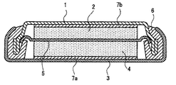
次に本発明を実施例により具体的に説明するが、本発明はこれら実施例に限定されるものではない。また以下の実施例および比較例では、図1に示すような構成の評価用ボタン型二次電池を作製して評価したが、実電池は、本発明の概念に基づき、公知の方法に準じて作製することができる。 EXAMPLES Next, although an Example demonstrates this invention concretely, this invention is not limited to these Examples. Further, in the following examples and comparative examples, evaluation button type secondary batteries having a configuration as shown in FIG. 1 were prepared and evaluated, but the actual batteries are based on the concept of the present invention and according to known methods. Can be produced.
(実施例1)
厚さ20μmの銅箔を塩化錫水溶液に漬し、錫めっきした後、該錫めっき銅箔を300℃に2秒間加熱すると同時に、錫めっき層表面に窒素ガスを吹き付け、銅箔上に単位面積当り目付け量が1.0mg/cm2の錫の薄層を形成した。該薄層の厚さは2.8μmであり、錫の薄層は、平均粒径が3.0μmの粒子状に分布しており、面積率は50%であった。
コールタールピッチを熱処理し、メソカーボン小球体を生成させ、抽出ろ過して得たメソカーボン小球体を焼成し、黒鉛化して得られたメソカーボン小球体黒鉛化物90質量%と、結合剤としてポリフッ化ビニリデン10質量%とを、N−メチルピロリドンを溶媒として混合し、ホモミキサーを用いて500rpmで5分間攪拌し、有機溶媒系負極合剤ペーストを調製した。
該負極合剤ペーストを、前記の錫の薄層を有する銅箔(集電体7b)上に、その塗布量が11mg/cm2となるように塗布し、さらに真空中において90℃で溶剤を揮発させて乾燥した。次に、この銅箔上に塗布された負極合剤をローラープレスによって加圧し、さらに直径15.5mmの円形状に打ち抜くことで、炭素材料層(付着量:10mg/cm2)が錫の薄層(厚さ:2.8μm)を介して銅箔(厚さ:20μm)に密着した作用電極2を作製した。
(Example 1)
A copper foil having a thickness of 20 μm is immersed in a tin chloride aqueous solution and tin-plated. Then, the tin-plated copper foil is heated to 300 ° C. for 2 seconds, and at the same time, nitrogen gas is blown onto the surface of the tin-plated layer, thereby unit area on the copper foil. A thin layer of tin with a basis weight of 1.0 mg / cm 2 was formed. The thin layer had a thickness of 2.8 μm, the tin thin layer was distributed in the form of particles having an average particle diameter of 3.0 μm, and the area ratio was 50%.
The coal tar pitch is heat-treated to form mesocarbon spherules, and the mesocarbon spherules obtained by extraction and filtration are calcined and graphitized, and 90% by mass of the mesocarbon spherulite graphitized product and polyfluoride as a binder. 10% by mass of vinylidene chloride was mixed with N-methylpyrrolidone as a solvent, and stirred at 500 rpm for 5 minutes using a homomixer to prepare an organic solvent-based negative electrode mixture paste.
The negative electrode mixture paste was applied on the copper foil (
対極4は、リチウム金属箔を、ニッケルネットに押付け、直系15.5mmの円形状に打ち抜いて、ニッケルネットからなる集電体(7a)とし、該集電体にリチウム金属箔を密着させて作製した。
エチレンカーボネート33質量%、メチルエチルカーボネート67質量%の割合で混合してなる溶媒に、LiPF6を1mol/Lとなる濃度で溶解させ、非水電解液を調製した。得られた非水電解液をポリプロピレン多孔質体に含浸させ、電解質液が含浸されたセパレーター5を作製した。
The counter electrode 4 is manufactured by pressing a lithium metal foil onto a nickel net and punching it into a circular shape of direct 15.5 mm to form a current collector (7a) made of nickel net, and the lithium metal foil is adhered to the current collector. did.
LiPF 6 was dissolved at a concentration of 1 mol / L in a solvent prepared by mixing 33% by mass of ethylene carbonate and 67% by mass of methyl ethyl carbonate to prepare a nonaqueous electrolytic solution. The obtained non-aqueous electrolyte solution was impregnated into a polypropylene porous body to produce a separator 5 impregnated with the electrolyte solution.
評価電池として図1に示すボタン型二次電池を作製した。
評価電池は、外装カップ1と外装缶3とが、その周辺部において絶縁ガスケット6を介してかしめられた密閉構造を有し、その内部に、外装缶3の内面から順に、ニッケルネットからなる集電体7a、リチウム箔よりなる円盤状の作用電極2および銅箔からなる集電体7bが積層された電池系である。
評価電池は、電解質溶液を含浸させたセパレーター5を、集電体7bに密着した作用電極2と、集電体7aに密着した対極4との間に挟んで積層した後、作用電極2を外装カップ1内に、対極4を外装缶3内に収容して、外装カップ1と外装缶3とを合わせ、外装カップ1と外装缶3との周辺部を、絶縁ガスケット6を介してかしめ密閉して作製した。
A button-type secondary battery shown in FIG. 1 was produced as an evaluation battery.
The evaluation battery has a sealed structure in which the
The evaluation battery was prepared by laminating the separator 5 impregnated with the electrolyte solution between the working
この評価電池について、25℃の温度で下記のような充放電試験を行った。
0.9mAの電流値で回路電圧が0mVに達するまで定電流充電を行い、回路電圧が0mVに達した時点で定電圧充電に切り替え、さらに電流値が20μAになるまで充電を続けた。その間の通電量から充電容量を求めた。その後、120分間休止した。
次に0.9mAの電流値で、回路電圧が1.5Vに達するまで定電流充電を行い、その間の通電量から放電容量を求めた。
なお、この試験では、リチウムイオンを炭素材料中に吸蔵する過程を充電、炭素材料から脱離する過程を放電とした。
放電容量は402mAh/gであり、天然黒鉛の理論値372mAh/gを超える高容量であった。
また、このときの充放電後の負極を取り出して、充放電後の作用電極の厚さを測定し、充放電前の作用電極の厚さと比較した。なお、作用電極の厚さは、マイクロメーターで測定した。また、次式から作用電極の充放電前後の間の膨張率を計算した。膨張率は18%であった。
膨張率(%)=[(充放電後の厚さ−充電前の厚さ)/充電前の厚さ]×100
About this evaluation battery, the following charging / discharging test was done at the temperature of 25 degreeC.
Constant current charging was performed until the circuit voltage reached 0 mV at a current value of 0.9 mA, and switching to constant voltage charging was performed when the circuit voltage reached 0 mV, and charging was continued until the current value reached 20 μA. The charging capacity was determined from the amount of electricity applied during that time. Then, it rested for 120 minutes.
Next, constant current charging was performed at a current value of 0.9 mA until the circuit voltage reached 1.5 V, and the discharge capacity was obtained from the energization during that time.
In this test, the process of occluding lithium ions in the carbon material was charged, and the process of desorbing from the carbon material was discharge.
The discharge capacity was 402 mAh / g, which was a high capacity exceeding the theoretical value of 372 mAh / g of natural graphite.
Moreover, the negative electrode after charging / discharging at this time was taken out, the thickness of the working electrode after charging / discharging was measured, and it compared with the thickness of the working electrode before charging / discharging. The thickness of the working electrode was measured with a micrometer. Moreover, the expansion coefficient before and behind charging / discharging of a working electrode was computed from following Formula. The expansion rate was 18%.
Expansion rate (%) = [(thickness after charging / discharging−thickness before charging) / thickness before charging] × 100
(実施例2)
実施例1において、錫の薄層の目付け量を2.0mg/cm2とし、層厚を4.5μm、面積率を60%とする以外は、実施例1と同様な方法と条件で、作用電極および評価電池を作製し、実施例1と同様に、充放電試験を行った。放電容量は453mAh/gであり、膨張率は23%であった。
(Example 2)
In Example 1, the same method and conditions as in Example 1 were used except that the basis weight of the thin tin layer was 2.0 mg / cm 2 , the layer thickness was 4.5 μm, and the area ratio was 60%. An electrode and an evaluation battery were prepared, and a charge / discharge test was conducted in the same manner as in Example 1. The discharge capacity was 453 mAh / g, and the expansion rate was 23%.
(比較例1)
実施例1において、錫の薄層の目付け量を5.0mg/cm2とし、層厚を14.0μm、面積率を50%とし、かつ炭素材料層を省略する以外は、実施例1と同様な方法と条件で、作用電極および評価電池を作製し、実施例1と同様に、充放電試験を行った。放電容量は991mAh/gであり、膨張率は53%であった。
(Comparative Example 1)
In Example 1, the basis weight of the thin tin layer was 5.0 mg / cm 2 , the layer thickness was 14.0 μm, the area ratio was 50%, and the carbon material layer was omitted. Under the same method and conditions, working electrodes and evaluation batteries were produced, and charge / discharge tests were conducted in the same manner as in Example 1. The discharge capacity was 991 mAh / g, and the expansion rate was 53%.
(比較例2)
実施例1において、錫の薄層がない銅箔を用いる以外は、実施例1と同様な方法と条件で、作用電極よび評価電池を作製し、実施例1と同様に、充放電試験を行った。放電容量は345mAh/gであり、膨張率は14%であった。
(Comparative Example 2)
A working electrode and an evaluation battery were produced in the same manner and in the same manner as in Example 1 except that a copper foil without a thin tin layer was used in Example 1, and a charge / discharge test was conducted in the same manner as in Example 1. It was. The discharge capacity was 345 mAh / g, and the expansion rate was 14%.
(比較例3)
実施例2において、錫の薄層の目付け量を3.3mg/cm2とし、層厚を4.5μm、面積率を100%とする以外は、実施例2と同様な方法と条件で、作用電極および評価電池を作製し、実施例1と同様に、充放電試験を行った。放電容量は563mAh/gであり、膨張率は35%であった。
(Comparative Example 3)
In Example 2, the same method and conditions as in Example 2 were used except that the basis weight of the thin tin layer was 3.3 mg / cm 2 , the layer thickness was 4.5 μm, and the area ratio was 100%. An electrode and an evaluation battery were prepared, and a charge / discharge test was conducted in the same manner as in Example 1. The discharge capacity was 563 mAh / g, and the expansion rate was 35%.
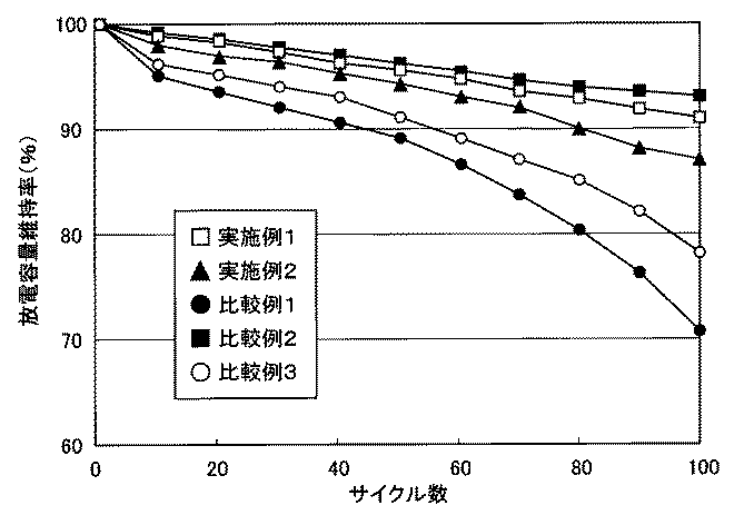
次に、実施例1〜2および比較例1〜3によって作製した作用電極を用いて、エチレンカーボネート(EC)とエチルメチルカーボネート(EMC)を体積比1:2とした溶媒に、LiPF6を1mol/Lの濃度とした非水系電解液を用い、対極をコバルト酸リチウムとし、該作用電極と対極の間を多孔質のセパレーターで介して評価電池を別途作製した。該作用電極を用いて、放電容量維持率を求めた。その結果を図2に示した。なお、放電容量維持率は、初回の放電容量を100%としたときの各サイクルの放電容量の変化をいう。 Next, 1 mol of LiPF 6 was added to a solvent in which ethylene carbonate (EC) and ethyl methyl carbonate (EMC) were in a volume ratio of 1: 2 using the working electrodes prepared in Examples 1-2 and Comparative Examples 1-3. A non-aqueous electrolyte solution having a concentration of / L was used, the counter electrode was lithium cobalt oxide, and an evaluation battery was separately prepared through a porous separator between the working electrode and the counter electrode. Using the working electrode, the discharge capacity retention rate was determined. The results are shown in FIG. The discharge capacity maintenance rate refers to a change in discharge capacity in each cycle when the initial discharge capacity is 100%.
第100サイクルでの放電容量維持率は、比較例2の集電体に錫の薄層を有していないものが93%で最も良く、実施例1、2の集電体に錫の薄層を有するものが91%と87%で次いで良かった。一方、比較例3の面積率100%の錫の薄層を有するものは78%、比較例1の集電体に炭素材料層を有しないものは71%と低かった。
以上から、実施例1〜2のように集電体に所定の面積率の金属の薄層を有する負極を用いると、放電容量が高く、かつサイクル特性(放電容量維持率)に優れたリチウムイオン二次電池が製造可能である。
The discharge capacity maintenance rate in the 100th cycle is best when the current collector of Comparative Example 2 does not have a thin tin layer, and is 93%, and the current collector of Examples 1 and 2 has a thin tin layer. The one with 91 was 87% and 87%. On the other hand, those having a tin layer of 100% area ratio in Comparative Example 3 were as low as 78%, and those having no carbon material layer in the current collector of Comparative Example 1 were as low as 71%.
From the above, when a negative electrode having a thin metal layer with a predetermined area ratio is used for the current collector as in Examples 1 and 2, lithium ions with high discharge capacity and excellent cycle characteristics (discharge capacity retention rate) A secondary battery can be manufactured.
本発明の負極を用いたリチウムイオン二次電池は、小型電子機器に搭載され、その高性能化、高機能化に貢献することができる。 A lithium ion secondary battery using the negative electrode of the present invention is mounted on a small electronic device and can contribute to higher performance and higher functionality.
1 外装カップ
2 作用電極
3 外装缶
4 対極
5 電解質溶液含浸セパレーター
6 絶縁ガスケット
7a、7b 集電体
DESCRIPTION OF
Claims (4)
Priority Applications (1)
| Application Number | Priority Date | Filing Date | Title |
|---|---|---|---|
| JP2004105610A JP2005293960A (en) | 2004-03-31 | 2004-03-31 | Negative electrode for lithium ion secondary battery and lithium ion secondary battery |
Applications Claiming Priority (1)
| Application Number | Priority Date | Filing Date | Title |
|---|---|---|---|
| JP2004105610A JP2005293960A (en) | 2004-03-31 | 2004-03-31 | Negative electrode for lithium ion secondary battery and lithium ion secondary battery |
Publications (1)
| Publication Number | Publication Date |
|---|---|
| JP2005293960A true JP2005293960A (en) | 2005-10-20 |
Family
ID=35326677
Family Applications (1)
| Application Number | Title | Priority Date | Filing Date |
|---|---|---|---|
| JP2004105610A Pending JP2005293960A (en) | 2004-03-31 | 2004-03-31 | Negative electrode for lithium ion secondary battery and lithium ion secondary battery |
Country Status (1)
| Country | Link |
|---|---|
| JP (1) | JP2005293960A (en) |
Cited By (12)
| Publication number | Priority date | Publication date | Assignee | Title |
|---|---|---|---|---|
| JP2007200862A (en) * | 2005-12-28 | 2007-08-09 | Sanyo Electric Co Ltd | Nonaqueous electrolyte secondary battery |
| JP2007273182A (en) * | 2006-03-30 | 2007-10-18 | Sony Corp | Current collector, negative electrode and battery |
| KR101397415B1 (en) | 2011-02-11 | 2014-05-20 | 한양대학교 산학협력단 | Lithiated metal carbon composite, method for preparing the same, and electrochemical device comprising the same |
| JP2014531120A (en) * | 2011-10-25 | 2014-11-20 | エルジー・ケム・リミテッド | Secondary battery negative electrode and secondary battery including the same |
| US9728786B2 (en) | 2015-12-21 | 2017-08-08 | Nissan North America, Inc. | Electrode having active material encased in conductive net |
| WO2017217823A1 (en) * | 2016-06-17 | 2017-12-21 | 주식회사 엘지화학 | Electrode for secondary battery and method for manufacturing same |
| KR20170142915A (en) * | 2016-06-17 | 2017-12-28 | 주식회사 엘지화학 | Electrode for secondary battery and preparing method thereof |
| US10038195B2 (en) | 2015-11-30 | 2018-07-31 | Nissan North America, Inc. | Electrode structure having structured conductive buffer layer |
| US10103386B2 (en) | 2015-12-15 | 2018-10-16 | Nissan North America, Inc. | Electrode with modified current collector structure and method of making the same |
| US10199655B2 (en) | 2015-11-30 | 2019-02-05 | Nissan North America, Inc. | Electrode structure having structured conductive buffer layer |
| US10319987B2 (en) | 2015-12-21 | 2019-06-11 | Nissan North America, Inc. | Active material with expansion structure for use in lithium ion batteries |
| KR20220060804A (en) * | 2020-11-05 | 2022-05-12 | 주식회사 엘지에너지솔루션 | Anode for Lithium Secondary Battery Comprising Lithiophilic Material Layer and Carbon Layer, Method for Manufacturing thereof, and Lithium Secondary Battery Comprising the Anode for Lithium Secondary Battery |
Citations (5)
| Publication number | Priority date | Publication date | Assignee | Title |
|---|---|---|---|---|
| JPH1092414A (en) * | 1996-09-11 | 1998-04-10 | Matsushita Denchi Kogyo Kk | Nonaqueous electrolyte secondary battery |
| JP2001283833A (en) * | 2000-04-03 | 2001-10-12 | Sanyo Electric Co Ltd | Secondary battery |
| JP2001283834A (en) * | 2000-04-03 | 2001-10-12 | Sanyo Electric Co Ltd | Secondary battery |
| JP2002015729A (en) * | 2000-06-30 | 2002-01-18 | Toshiba Corp | Non-aqueous electrolyte secondary battery |
| JP2002279974A (en) * | 2001-03-19 | 2002-09-27 | Sanyo Electric Co Ltd | Method of manufacturing electrode for secondary battery |
-
2004
- 2004-03-31 JP JP2004105610A patent/JP2005293960A/en active Pending
Patent Citations (5)
| Publication number | Priority date | Publication date | Assignee | Title |
|---|---|---|---|---|
| JPH1092414A (en) * | 1996-09-11 | 1998-04-10 | Matsushita Denchi Kogyo Kk | Nonaqueous electrolyte secondary battery |
| JP2001283833A (en) * | 2000-04-03 | 2001-10-12 | Sanyo Electric Co Ltd | Secondary battery |
| JP2001283834A (en) * | 2000-04-03 | 2001-10-12 | Sanyo Electric Co Ltd | Secondary battery |
| JP2002015729A (en) * | 2000-06-30 | 2002-01-18 | Toshiba Corp | Non-aqueous electrolyte secondary battery |
| JP2002279974A (en) * | 2001-03-19 | 2002-09-27 | Sanyo Electric Co Ltd | Method of manufacturing electrode for secondary battery |
Cited By (19)
| Publication number | Priority date | Publication date | Assignee | Title |
|---|---|---|---|---|
| JP2007200862A (en) * | 2005-12-28 | 2007-08-09 | Sanyo Electric Co Ltd | Nonaqueous electrolyte secondary battery |
| US9640830B2 (en) | 2006-03-30 | 2017-05-02 | Sony Corporation | Current collector, negative electrode and battery |
| JP2007273182A (en) * | 2006-03-30 | 2007-10-18 | Sony Corp | Current collector, negative electrode and battery |
| US9742039B2 (en) | 2006-03-30 | 2017-08-22 | Sony Corporation | Current collector, negative electrode and battery |
| US9350050B2 (en) | 2006-03-30 | 2016-05-24 | Sony Corporation | Current collector, negative electrode and battery |
| KR101397415B1 (en) | 2011-02-11 | 2014-05-20 | 한양대학교 산학협력단 | Lithiated metal carbon composite, method for preparing the same, and electrochemical device comprising the same |
| US9005819B2 (en) | 2011-10-25 | 2015-04-14 | Lg Chem, Ltd. | Anode for secondary battery and secondary battery having the same |
| JP2014531120A (en) * | 2011-10-25 | 2014-11-20 | エルジー・ケム・リミテッド | Secondary battery negative electrode and secondary battery including the same |
| US10038195B2 (en) | 2015-11-30 | 2018-07-31 | Nissan North America, Inc. | Electrode structure having structured conductive buffer layer |
| US10199655B2 (en) | 2015-11-30 | 2019-02-05 | Nissan North America, Inc. | Electrode structure having structured conductive buffer layer |
| US10103386B2 (en) | 2015-12-15 | 2018-10-16 | Nissan North America, Inc. | Electrode with modified current collector structure and method of making the same |
| US9728786B2 (en) | 2015-12-21 | 2017-08-08 | Nissan North America, Inc. | Electrode having active material encased in conductive net |
| US10319987B2 (en) | 2015-12-21 | 2019-06-11 | Nissan North America, Inc. | Active material with expansion structure for use in lithium ion batteries |
| WO2017217823A1 (en) * | 2016-06-17 | 2017-12-21 | 주식회사 엘지화학 | Electrode for secondary battery and method for manufacturing same |
| KR20170142915A (en) * | 2016-06-17 | 2017-12-28 | 주식회사 엘지화학 | Electrode for secondary battery and preparing method thereof |
| US10573925B2 (en) | 2016-06-17 | 2020-02-25 | Lg Chem, Ld. | Electrode for secondary battery and method of manufacturing the same |
| KR102149299B1 (en) * | 2016-06-17 | 2020-08-28 | 주식회사 엘지화학 | Electrode for secondary battery and preparing method thereof |
| KR20220060804A (en) * | 2020-11-05 | 2022-05-12 | 주식회사 엘지에너지솔루션 | Anode for Lithium Secondary Battery Comprising Lithiophilic Material Layer and Carbon Layer, Method for Manufacturing thereof, and Lithium Secondary Battery Comprising the Anode for Lithium Secondary Battery |
| KR102880258B1 (en) | 2020-11-05 | 2025-11-03 | 주식회사 엘지에너지솔루션 | Anode for Lithium Secondary Battery Comprising Lithiophilic Material Layer and Carbon Layer, Method for Manufacturing thereof, and Lithium Secondary Battery Comprising the Anode for Lithium Secondary Battery |
Similar Documents
| Publication | Publication Date | Title |
|---|---|---|
| JP3797197B2 (en) | Nonaqueous electrolyte secondary battery | |
| JP5158193B2 (en) | Lithium air battery | |
| JP4022889B2 (en) | Electrolyte and battery | |
| JP3959708B2 (en) | Method for producing positive electrode for lithium battery and positive electrode for lithium battery | |
| JP3535454B2 (en) | Non-aqueous electrolyte secondary battery | |
| JP2009021134A (en) | Nonaqueous electrolyte battery and battery pack | |
| JP2002203553A (en) | Cathode active material and non-aqueous electrolyte secondary battery | |
| JPH09259929A (en) | Lithium secondary battery | |
| JP4591674B2 (en) | Lithium ion secondary battery | |
| JP3819663B2 (en) | Lithium secondary battery charge / discharge method and lithium secondary battery | |
| JP2005293960A (en) | Negative electrode for lithium ion secondary battery and lithium ion secondary battery | |
| JP2003123767A (en) | Current collectors, electrodes and batteries | |
| JP2008166156A (en) | Storage element | |
| JPH11204145A (en) | Lithium secondary battery | |
| JP2005071918A (en) | Negative electrode for lithium ion secondary battery and lithium ion secondary battery | |
| JP4849291B2 (en) | Secondary battery | |
| JP4120439B2 (en) | Lithium ion secondary battery | |
| JP2004259485A (en) | Non-aqueous electrolyte secondary battery | |
| JP4664455B2 (en) | Non-aqueous electrolyte secondary battery | |
| JP2003168427A (en) | Non-aqueous electrolyte battery | |
| JP5272810B2 (en) | Capacitors | |
| WO2003067688A1 (en) | Nonaqueous electrolyte secondary cell | |
| JP2002313418A (en) | Non-aqueous electrolyte and non-aqueous electrolyte secondary battery | |
| JP2004193139A (en) | Non-aqueous electrolyte secondary battery | |
| JP2001015168A (en) | Lithium secondary battery |
Legal Events
| Date | Code | Title | Description |
|---|---|---|---|
| A621 | Written request for application examination |
Free format text: JAPANESE INTERMEDIATE CODE: A621 Effective date: 20070323 |
|
| A977 | Report on retrieval |
Free format text: JAPANESE INTERMEDIATE CODE: A971007 Effective date: 20100308 |
|
| A131 | Notification of reasons for refusal |
Free format text: JAPANESE INTERMEDIATE CODE: A131 Effective date: 20100427 |
|
| A02 | Decision of refusal |
Free format text: JAPANESE INTERMEDIATE CODE: A02 Effective date: 20100907 |