JP2005293955A - Coaxial microwave plasma torch - Google Patents
Coaxial microwave plasma torch Download PDFInfo
- Publication number
- JP2005293955A JP2005293955A JP2004105472A JP2004105472A JP2005293955A JP 2005293955 A JP2005293955 A JP 2005293955A JP 2004105472 A JP2004105472 A JP 2004105472A JP 2004105472 A JP2004105472 A JP 2004105472A JP 2005293955 A JP2005293955 A JP 2005293955A
- Authority
- JP
- Japan
- Prior art keywords
- outer conductor
- discharge tube
- conductor
- coaxial
- antenna
- Prior art date
- Legal status (The legal status is an assumption and is not a legal conclusion. Google has not performed a legal analysis and makes no representation as to the accuracy of the status listed.)
- Granted
Links
- 239000004020 conductor Substances 0.000 claims abstract description 146
- 230000002093 peripheral effect Effects 0.000 claims description 18
- 238000003780 insertion Methods 0.000 claims description 10
- 230000037431 insertion Effects 0.000 claims description 10
- 230000005540 biological transmission Effects 0.000 claims description 9
- 230000000149 penetrating effect Effects 0.000 abstract description 2
- 239000010453 quartz Substances 0.000 description 5
- VYPSYNLAJGMNEJ-UHFFFAOYSA-N silicon dioxide Inorganic materials O=[Si]=O VYPSYNLAJGMNEJ-UHFFFAOYSA-N 0.000 description 5
- 230000005684 electric field Effects 0.000 description 4
- 239000003989 dielectric material Substances 0.000 description 3
- 239000000463 material Substances 0.000 description 3
- 238000012986 modification Methods 0.000 description 3
- 230000004048 modification Effects 0.000 description 3
- PNEYBMLMFCGWSK-UHFFFAOYSA-N aluminium oxide Inorganic materials [O-2].[O-2].[O-2].[Al+3].[Al+3] PNEYBMLMFCGWSK-UHFFFAOYSA-N 0.000 description 2
- 239000011248 coating agent Substances 0.000 description 2
- 238000000576 coating method Methods 0.000 description 2
- 230000000694 effects Effects 0.000 description 2
- 239000012535 impurity Substances 0.000 description 2
- 230000033001 locomotion Effects 0.000 description 2
- VYZAMTAEIAYCRO-UHFFFAOYSA-N Chromium Chemical compound [Cr] VYZAMTAEIAYCRO-UHFFFAOYSA-N 0.000 description 1
- 229910052804 chromium Inorganic materials 0.000 description 1
- 239000011651 chromium Substances 0.000 description 1
- 238000010276 construction Methods 0.000 description 1
- 238000010292 electrical insulation Methods 0.000 description 1
- 238000005530 etching Methods 0.000 description 1
- 238000004381 surface treatment Methods 0.000 description 1
Images

Classifications
-
- H—ELECTRICITY
- H05—ELECTRIC TECHNIQUES NOT OTHERWISE PROVIDED FOR
- H05H—PLASMA TECHNIQUE; PRODUCTION OF ACCELERATED ELECTRICALLY-CHARGED PARTICLES OR OF NEUTRONS; PRODUCTION OR ACCELERATION OF NEUTRAL MOLECULAR OR ATOMIC BEAMS
- H05H1/00—Generating plasma; Handling plasma
- H05H1/24—Generating plasma
- H05H1/26—Plasma torches
- H05H1/30—Plasma torches using applied electromagnetic fields, e.g. high frequency or microwave energy
-
- H—ELECTRICITY
- H05—ELECTRIC TECHNIQUES NOT OTHERWISE PROVIDED FOR
- H05H—PLASMA TECHNIQUE; PRODUCTION OF ACCELERATED ELECTRICALLY-CHARGED PARTICLES OR OF NEUTRONS; PRODUCTION OR ACCELERATION OF NEUTRAL MOLECULAR OR ATOMIC BEAMS
- H05H1/00—Generating plasma; Handling plasma
- H05H1/24—Generating plasma
- H05H1/46—Generating plasma using applied electromagnetic fields, e.g. high frequency or microwave energy
- H05H1/461—Microwave discharges
- H05H1/463—Microwave discharges using antennas or applicators
-
- H—ELECTRICITY
- H05—ELECTRIC TECHNIQUES NOT OTHERWISE PROVIDED FOR
- H05H—PLASMA TECHNIQUE; PRODUCTION OF ACCELERATED ELECTRICALLY-CHARGED PARTICLES OR OF NEUTRONS; PRODUCTION OR ACCELERATION OF NEUTRAL MOLECULAR OR ATOMIC BEAMS
- H05H1/00—Generating plasma; Handling plasma
- H05H1/24—Generating plasma
- H05H1/46—Generating plasma using applied electromagnetic fields, e.g. high frequency or microwave energy
- H05H1/461—Microwave discharges
- H05H1/4637—Microwave discharges using cables
-
- H—ELECTRICITY
- H05—ELECTRIC TECHNIQUES NOT OTHERWISE PROVIDED FOR
- H05H—PLASMA TECHNIQUE; PRODUCTION OF ACCELERATED ELECTRICALLY-CHARGED PARTICLES OR OF NEUTRONS; PRODUCTION OR ACCELERATION OF NEUTRAL MOLECULAR OR ATOMIC BEAMS
- H05H1/00—Generating plasma; Handling plasma
- H05H1/24—Generating plasma
- H05H1/46—Generating plasma using applied electromagnetic fields, e.g. high frequency or microwave energy
- H05H1/461—Microwave discharges
- H05H1/4622—Microwave discharges using waveguides
Landscapes
- Physics & Mathematics (AREA)
- Engineering & Computer Science (AREA)
- Plasma & Fusion (AREA)
- Electromagnetism (AREA)
- Spectroscopy & Molecular Physics (AREA)
- Plasma Technology (AREA)
Abstract
【課題】 従来のものより小型でかつ高いエネルギー効率を有する同軸形マイクロ波プラズマトーチを提供する。
【解決手段】 円柱形状を有する外側導体1と、外側導体の一端面4側に形成された軸方向の孔2に挿入され、固定された円筒状の放電管3と、一端が、外側から外側導体の他端面に取り付けられた同軸ケーブル6を備える。同軸ケーブルの一端には、その内部導体8に電気的に接続されたアンテナ9が備えられ、アンテナは、外側導体の他端面5および軸方向の孔の底面の間を軸方向に貫通する貫通孔11を通って放電管内にのび、同軸ケーブルの外部導体7は外側導体に電気的に接続され、外側導体には、放電管内にガスを供給するガス導入管路13が設けられる。
【選択図】 図1PROBLEM TO BE SOLVED: To provide a coaxial microwave plasma torch which is smaller than a conventional one and has high energy efficiency.
SOLUTION: An outer conductor 1 having a columnar shape, a cylindrical discharge tube 3 inserted and fixed in an axial hole 2 formed on one end face 4 side of the outer conductor, and one end are connected from the outside to the outside. A coaxial cable 6 attached to the other end surface of the conductor is provided. One end of the coaxial cable is provided with an antenna 9 electrically connected to the inner conductor 8, and the antenna has a through-hole penetrating between the other end surface 5 of the outer conductor and the bottom surface of the axial hole in the axial direction. 11, the outer conductor 7 of the coaxial cable extends into the discharge tube, and is electrically connected to the outer conductor. The outer conductor is provided with a gas introduction pipe 13 for supplying gas into the discharge tube.
[Selection] Figure 1
Description
本発明は、マイクロ波プラズマトーチ、とりわけ、同軸形マイクロ波プラズマトーチに関するものである。 The present invention relates to a microwave plasma torch, and more particularly to a coaxial microwave plasma torch.
大気圧中においてプラズマを発生し得るマイクロ波プラズマトーチとしては、従来より、導波管形マイクロ波プラズマトーチが知られている(例えば特許文献1参照)。この従来の導波管形マイクロ波プラズマトーチは、スタブチューナ、導波管および反射板と大きく分けて3つの構成部分から構成され、さらには、大気圧中でプラズマを生成するために点火装置を必要とし、多数の構成部分を有している。そのため、装置の設計の自由度があまりなく、装置の小型化を図るには限界があるという問題を有していた。 As a microwave plasma torch capable of generating plasma in atmospheric pressure, a waveguide type microwave plasma torch has been known (see, for example, Patent Document 1). This conventional waveguide-type microwave plasma torch is roughly divided into a stub tuner, a waveguide and a reflector, and is composed of three components. Further, an ignition device is used to generate plasma at atmospheric pressure. It has many components. For this reason, there is not much freedom in designing the device, and there is a problem that there is a limit to downsizing the device.
この従来の導波管形プラズマトーチの欠点を解消するものとして、ヘリカル共振器の構造を引き継いだ構造を有する、同軸形マイクロ波プラズマトーチが提案されている(例えば特許文献2参照)。このマイクロ波プラズマトーチは、上端開口を蓋体によって閉じられた円筒状の外管からなる同軸形共振器と、この共振器の外管の上端寄りに外管に直角に連結された同軸線路とを備えている。そして、同軸線路の内部中央を通る導体が、外管内で上向きに蓋体方向に屈曲して蓋体の内端面に固定され、蓋体は、外管を通じ同軸線路の外部導体に接続され、さらに、蓋体の中央には、内部導体が固着され、内部導体は、棒状部と棒状部の先端に固着された電気伝導性をもつ電極からなり、外管の下方には、電極の周囲面に石英管が取付けられ、外管の周壁には、外側から電極に向けてガスを導入するガス導入口が設けられている。 As a solution to the drawbacks of the conventional waveguide plasma torch, a coaxial microwave plasma torch having a structure that inherits the structure of a helical resonator has been proposed (for example, see Patent Document 2). This microwave plasma torch includes a coaxial resonator composed of a cylindrical outer tube whose upper end opening is closed by a lid, and a coaxial line connected to the outer tube at a right angle near the upper end of the outer tube of the resonator. It has. A conductor passing through the inner center of the coaxial line is bent upward in the outer tube toward the lid body and fixed to the inner end surface of the lid body, and the lid body is connected to the outer conductor of the coaxial line through the outer tube, The inner conductor is fixed to the center of the lid, and the inner conductor is composed of a rod-shaped portion and an electrode having electrical conductivity fixed to the tip of the rod-shaped portion. A quartz tube is attached, and a gas inlet for introducing gas from the outside toward the electrode is provided on the peripheral wall of the outer tube.
このマイクロ波プラズマトーチにおいては、同軸線路に接続されたマイクロ波発振器によってマイクロ波が出力されると、マイクロ波は、同軸線路を通ることによって同軸モード(TEMモード)に変換されて伝送される。その後、マイクロ波は、同軸線路の内部中央を通る導体が共振器の外管内で蓋体方向に屈曲する部分で、一旦モード変換され、さらに、共振器内部で再び同軸モードに変換されて、内部導体によって電極に導かれ、電極の先端にはマイクロ波の電界が集中し、電界強度が最大となり、電極の先端からプラズマが発生するようになっている。 In this microwave plasma torch, when microwaves are output by a microwave oscillator connected to a coaxial line, the microwaves are converted to a coaxial mode (TEM mode) by passing through the coaxial line and transmitted. After that, the microwave is once converted into a mode where the conductor passing through the inner center of the coaxial line is bent in the direction of the lid inside the outer tube of the resonator, and further converted into the coaxial mode again inside the resonator. The electric field of the microwave is concentrated at the tip of the electrode by the conductor, the electric field strength is maximized, and plasma is generated from the tip of the electrode.
しかしながら、この構成によれば、共振器を使用するので、プラズマトーチをある程度の大きさに維持する必要があり、プラズマトーチを小型化することが困難であった。また、この構成によれば、マイクロ波は、同軸線路から共振器内に伝送される間に、同軸モードから一旦別のモードに変換された後、再び同軸モードに変換されるが、このようなモードの変換がなされると、それに対応してエネルギーの損失が生じ、エネルギー効率が低下するという問題があった。加えて、この構成では、大気圧中においてプラズマを点火させることは困難であった。
したがって、本発明の課題は、従来のものより小型でかつ高いエネルギー効率を有し、しかも、大気圧中で容易にプラズマを発生させることができる同軸形マイクロ波プラズマトーチを提供することにある。 Accordingly, an object of the present invention is to provide a coaxial microwave plasma torch that is smaller and more energy efficient than conventional ones, and that can easily generate plasma at atmospheric pressure.
上記課題を解決するため、第1発明は、円柱形状を有する外側導体と、前記外側導体の一端面側に形成された軸方向の孔に挿入され、固定された円筒状の放電管と、一端が、外側から前記外側導体の他端面に取り付けられた、マイクロ波伝送用の同軸ケーブルと、を備え、前記同軸ケーブルの一端には、その内部導体に電気的に接続されたアンテナが備えられ、前記外側導体には、その他端面側から前記軸方向の孔に向かって軸方向にのびる貫通孔が形成され、前記アンテナは、前記外側導体から電気的に絶縁された状態で前記貫通孔を通って前記放電管内にのび、前記同軸ケーブルの外部導体は前記外側導体に電気的に接続され、前記外側導体には、前記放電管内にガスを供給するガス導入管路が設けられていることを特徴とする同軸形マイクロ波プラズマトーチを構成したものである。 In order to solve the above problems, a first invention includes an outer conductor having a columnar shape, a cylindrical discharge tube inserted and fixed in an axial hole formed on one end face side of the outer conductor, and one end A coaxial cable for microwave transmission attached to the other end face of the outer conductor from the outside, and one end of the coaxial cable is provided with an antenna electrically connected to the inner conductor, A through hole extending in the axial direction from the other end surface side toward the axial hole is formed in the outer conductor, and the antenna passes through the through hole in a state of being electrically insulated from the outer conductor. The outer conductor of the coaxial cable extends in the discharge tube and is electrically connected to the outer conductor, and the outer conductor is provided with a gas introduction pipe for supplying gas into the discharge tube. Coaxial type My This is a construction of a Chromium plasma torch.
第1発明の構成において、好ましくは、前記外側導体の軸方向の孔の周面および前記放電管の外周面の間には、円筒状のスペースが形成され、前記円筒状のスペースは、前記外側導体の内部において、半径方向に予め決定された長さだけのび、前記軸方向の孔の底面から軸方向に任意の長さだけのびている。 In the configuration of the first invention, preferably, a cylindrical space is formed between a peripheral surface of the axial hole of the outer conductor and an outer peripheral surface of the discharge tube, and the cylindrical space is the outer space. Inside the conductor, it extends by a predetermined length in the radial direction and extends by an arbitrary length in the axial direction from the bottom surface of the axial hole.
また、上記課題を解決するため、第2発明は、円筒状の外側導体およびその内側に半径方向に間隔をあけて配置された円筒状の放電管からなる二重管構造を有するトーチ本体を備え、前記トーチ本体の前記外側導体は、その一端開口を蓋によって閉じられ、前記放電管は、一端が前記蓋に固定され、他端が前記外側導体の他端開口から突出してのび、前記トーチ本体の前記外側導体の蓋には、外側から、マイクロ波伝送用の同軸ケーブルの一端が取り付けられ、前記同軸ケーブルの一端には、その内部導体に電気的に接続されたアンテナが備えられ、前記アンテナは、前記蓋から電気的に絶縁された状態で、前記蓋に形成された貫通孔を通って前記トーチ本体の前記放電管内に軸方向にのび、前記同軸ケーブルの外部導体は前記トーチ本体の前記外側導体に電気的に接続され、前記トーチ本体には、前記トーチ本体の前記放電管内にガスを供給するガス導入管路が設けられていることを特徴とする同軸形マイクロ波プラズマトーチを構成したものである。 In order to solve the above-mentioned problems, the second invention includes a torch body having a double tube structure comprising a cylindrical outer conductor and a cylindrical discharge tube disposed radially inside the outer conductor. The outer conductor of the torch body is closed at one end by a lid, and the discharge tube has one end fixed to the lid and the other end protruding from the other end opening of the outer conductor. One end of a coaxial cable for microwave transmission is attached to the lid of the outer conductor from the outside, and an antenna electrically connected to the inner conductor is provided at one end of the coaxial cable. Extends axially into the discharge tube of the torch body through a through hole formed in the lid in a state of being electrically insulated from the lid, and the outer conductor of the coaxial cable is connected to the torch body. A coaxial microwave plasma torch comprising a gas introduction pipe for supplying gas into the discharge tube of the torch body is electrically connected to the outer conductor. It is a thing.
第2発明の構成において、好ましくは、前記トーチ本体における前記外側導体および前記放電管の間に形成された円筒状スペース内には、円筒状の補助導体が前記外側導体の他端開口側から嵌め込まれ、前記補助導体は、前記外側導体の内周面との間および前記放電管の外周面との間にマイクロ波の漏れを生じさせることなく、かつ前記トーチ本体の前記外側導体と電気的に接触しつつ前記放電管の軸方向に沿ってスライド運動することによって、マイクロ波の位相を適当に変化させ得るようになっている。
また好ましくは、前記ガス導入管路は、前記トーチ本体の外側から、前記外側導体および前記蓋の両方またはいずれか一方を貫通して前記外側導体および前記放電管の間の円筒状スペース内にのびた後、前記放電管に接続され、前記放電管における前記アンテナの先端近傍領域に開口している。あるいは、前記トーチ本体の前記蓋は、円柱状の誘電体からなる、前記外側導体内に挿入される差込部を少なくとも有し、前記放電管の一端は前記差込部に固定され、前記ガス導入管路は、前記トーチ本体の外側から、前記トーチ本体の前記外側導体を貫通する電気絶縁性をもつ管部分と、前記管部分に接続され、前記蓋の差込部を貫通する第1管路部分と、前記第1管路部分に接続され、前記アンテナ内部を内側にのびた後、そこから前記アンテナ内部をその先端に向かって軸方向にのび、前記先端に開口する第2管路部分とからなっている。
In the configuration of the second invention, preferably, a cylindrical auxiliary conductor is fitted from the other end opening side of the outer conductor into a cylindrical space formed between the outer conductor and the discharge tube in the torch body. The auxiliary conductor is electrically connected to the outer conductor of the torch body without causing leakage of microwaves between the inner peripheral surface of the outer conductor and the outer peripheral surface of the discharge tube. The phase of the microwave can be appropriately changed by sliding movement along the axial direction of the discharge tube while being in contact.
Preferably, the gas introduction pipe extends from the outside of the torch main body through the outer conductor and / or the lid into a cylindrical space between the outer conductor and the discharge tube. After that, it is connected to the discharge tube and opens in a region near the tip of the antenna in the discharge tube. Alternatively, the lid of the torch body has at least an insertion part that is made of a cylindrical dielectric and is inserted into the outer conductor, and one end of the discharge tube is fixed to the insertion part, and the gas The introduction pipe line includes an electrically insulating tube portion that penetrates the outer conductor of the torch body from the outside of the torch body, and a first tube that is connected to the tube portion and penetrates the plug insertion portion. A second pipe part connected to the first pipe part, extending inside the antenna inward, extending axially from the inside toward the tip of the antenna, and opening at the tip It is made up of.
第1および第2発明の構成において、好ましくは、前記アンテナは、前記同軸ケーブルの内部導体からなっている。 In the configurations of the first and second inventions, preferably, the antenna is made of an inner conductor of the coaxial cable.
本発明によれば、プラズマトーチの全体が同軸構造を保持し、よって、従来のマイクロ波プラズマトーチとは異なり、共振器を備えていないので、同軸ケーブル中を伝送されるマイクロ波は、同軸モードのままでアンテナに供給され、アンテナの先端でプラズマが発生する。したがって、プラズマトーチのエネルギー効率が従来より格段に高くなり、また、大気圧中でも容易にプラズマを生成することができる。また、本発明によれば、従来の導波管形のプラズマトーチとは異なり、整合器や反射板を用いる必要がないので、より大きな設計の自由度が得られ、プラズマトーチを小型化することができる。 According to the present invention, the entire plasma torch maintains a coaxial structure, and therefore, unlike a conventional microwave plasma torch, it does not include a resonator. It is supplied to the antenna as it is, and plasma is generated at the tip of the antenna. Therefore, the energy efficiency of the plasma torch becomes much higher than before, and plasma can be easily generated even at atmospheric pressure. In addition, according to the present invention, unlike the conventional waveguide type plasma torch, since there is no need to use a matching unit or a reflecting plate, a greater degree of design freedom can be obtained and the plasma torch can be downsized. Can do.
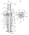
以下、添付図面を参照して本発明の好ましい実施例について説明する。図1は、本発明の1実施例による同軸形マイクロ波プラズマトーチを示したもので、(A)は側断面図でり、(B)は(A)の矢印A方向から見た平面図である。図1を参照して、本発明の同軸形マイクロ波プラズマトーチは、円柱形状を有する外側導体1と、外側導体1の一端面4側に形成された軸方向の孔2に挿入され、固定された円筒状の放電管3と、一端が、外側から外側導体1の他端面5に取り付けられた、マイクロ波伝送用の同軸ケーブル6を備えている。
この実施例では、外側導体1は、一端面4側の円柱状の第1部分1aと、他端面5側の円柱状の第2部分1bの2つの部分を接合したものからなっている。また、軸方向の孔2は、外側導体1の中心軸に沿ってのび、放電管3は外側導体1と同軸に配置されている。また、放電管3は、石英管およびアルミナ管等の誘電体から形成されている。
Hereinafter, preferred embodiments of the present invention will be described with reference to the accompanying drawings. 1A and 1B show a coaxial microwave plasma torch according to an embodiment of the present invention, in which FIG. 1A is a side sectional view and FIG. 1B is a plan view seen from the direction of arrow A in FIG. is there. Referring to FIG. 1, a coaxial microwave plasma torch according to the present invention is inserted and fixed in an outer conductor 1 having a cylindrical shape and an
In this embodiment, the outer conductor 1 is formed by joining two portions of a cylindrical first portion 1a on the one end face 4 side and a cylindrical second portion 1b on the
同軸ケーブル6の一端には、その内部導体8に電気的に接続されたアンテナ9が備えられている。この実施例では、同軸ケーブル6の一端に同軸コネクタ10が取り付けられ、この同軸コネクタ10を介して同軸ケーブル6の内部導体8とアンテナ9が電気的に接続される。また、外側導体1には、その他端面5側から軸方向の孔2に向かって軸方向にのびる貫通孔11が形成され、アンテナ9が、外側導体1から電気的に絶縁された状態で貫通孔11を通って放電管3内に突出するようにして、同軸コネクタ10がボルト12によって外側導体1の他端面5に取り付けられる。この場合、ボルト12は、同軸コネクタ10を外側導体1に取付けるだけでなく、外側導体1の第1部分1aおよび第2部分1bを互いに接合するためにも使用される。同時に、同軸ケーブル6の外部導体7は同軸コネクタ10を介して外側導体1に電気的に接続される。
アンテナ9は、高い電気伝導性を有する材料から形成されている。そして、アンテナ9と外側導体1の貫通孔11とは半径方向に間隔をあけて配置され、それによって、アンテナ9および外側導体1は互いに電気的に絶縁されている。アンテナ9には、プラズマ発生時に、プラズマへの不純物の混入を防止すべく、適当な表面コーティングが施されていることが好ましい。アンテナ9は、この実施例では、同軸ケーブル6の内部導体8とは別個のものとして形成されているが、アンテナ9を内部導体8から形成してもよい。
One end of the coaxial cable 6 is provided with an
The
外側導体1の軸方向の孔2は、当該孔2の底面から軸方向に任意の長さだけ(しかし、外側導体1の一端面4に達することはない)のび、その径が放電管3の外径より予め決定された長さだけ大きくなっており、この領域(外側導体1の内部)において、孔2の内周面および放電管3の外周面の間に、半径方向に予め決定された厚さを有し、任意の長さを有する円筒状のスペース14が形成される。
円筒状のスペース14は、伝送インピーダンスの整合をとるために使用される。伝送インピーダンスの整合は、同軸ケーブル6の内部導体8と外部導体7の径の比率と、アンテナ9の外径と外側導体1の内径の比率を一致させることによってなされる。この場合、外側導体1内部における円筒状のスペース14の半径方向の長さによって、外側導体1の内径が決定される。なお、外側導体1および放電管3の間に円筒状のスペース14を設ける必要がない場合もある。
The
The
外側導体1には、放電管3内にガスを供給するガス導入管路13が設けられている。ガス導入管路13は、石英管等の誘電体からなる管からなり、外側導体1の外側から、外側導体1に形成された半径方向の貫通孔を通って円筒状のスペース14内にのび、その一端が放電管3に接続され、放電管3内に開口している。
The outer conductor 1 is provided with a
こうして、大気圧中において、同軸ケーブル6の他端に、(図示されない)マイクロ波発振器が接続され、マイクロ波発振器から所定の波長のマイクロ波が出力される。また、ガス導入管路13には、(図示されない)ガス供給源が接続される。そして、ガス供給源からガス導入管路13を通じて放電管9内にガスが導入されるとともに、マイクロ波発振器から出力されたマイクロ波が、同軸ケーブル6中を伝送され、同軸コネクタ10を介してアンテナ9に同軸モードで伝送される。そして、マイクロ波は、アンテナ9表面を伝わり、アンテナ9の先端で最も高い電界が生じ、プラズマが、アンテナ9の先端と放電管3の内壁との間において生成され、放電管3の先端開口から照射される。
Thus, a microwave oscillator (not shown) is connected to the other end of the coaxial cable 6 at atmospheric pressure, and a microwave having a predetermined wavelength is output from the microwave oscillator. Further, a gas supply source (not shown) is connected to the gas
本発明による同軸形マイクロ波プラズマトーチは、全体が同軸構造を保持していて、従来の同軸形共振器を使用したマイクロ波プラズマトーチのように共振器を備えていないので、同軸ケーブル中を伝送されるマイクロ波は、同軸モードのままでアンテナに供給され、プラズマが発生する。したがって、プラズマトーチのエネルギー効率が従来より格段に高くなり、また大気圧中でも容易に点火させてプラズマを維持することができる。また、本発明によれば、従来の導波管形のプラズマトーチのように整合器や反射板を用いる必要がなく、プラズマトーチの構成部品点数が少なくて済むので、より大きな設計の自由度が得られ、プラズマトーチを小型化することができる。 The coaxial microwave plasma torch according to the present invention has a coaxial structure as a whole, and does not have a resonator like a microwave plasma torch using a conventional coaxial resonator, and therefore transmits through a coaxial cable. The microwave is supplied to the antenna in the coaxial mode, and plasma is generated. Therefore, the energy efficiency of the plasma torch becomes much higher than before, and the plasma can be maintained by being easily ignited even at atmospheric pressure. In addition, according to the present invention, it is not necessary to use a matching unit or a reflection plate as in the conventional waveguide type plasma torch, and the number of components of the plasma torch can be reduced. As a result, the plasma torch can be reduced in size.
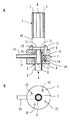
図2は、本発明の別の実施例による同軸形マイクロ波プラズマトーチを示したものであり、(A)は側断面図であり、(B)は(A)におけるX−X線に沿った断面図である。図2に示されるように、本発明の同軸形マイクロ波プラズマトーチは、円筒状の外側導体21と、その内側に半径方向に間隔をあけて配置された放電管22とからなる二重管構造を有するトーチ本体20を備えている。
FIG. 2 shows a coaxial microwave plasma torch according to another embodiment of the present invention, in which (A) is a side sectional view and (B) is taken along line XX in (A). It is sectional drawing. As shown in FIG. 2, the coaxial microwave plasma torch of the present invention has a double tube structure comprising a cylindrical
トーチ本体20の外側導体21は、その一端開口を蓋23によって閉じられている。この実施例では、蓋23は導電性を有する材料から形成されている。放電管22は、一端22aが蓋23に固定され、他端22bが外側導体21の他端開口21aから突出してのびている。放電管22は、石英管およびアルミナ管等の誘電体から形成されており、蓋23から電気的に絶縁されている。また、トーチ本体20の外側導体21の蓋23には、外側から、マイクロ波伝送用の同軸ケーブル24の一端が取り付けられ、同軸ケーブル24の一端にはその内部導体25に電気的に接続されたアンテナ28が備えられている。
One end opening of the
この実施例では、同軸ケーブル24の一端に同軸コネクタ27が取り付けられ、この同軸コネクタ27を介して同軸ケーブル24の内部導体25とアンテナ28が電気的に接続される。そして、アンテナ28が、蓋23から電気的に絶縁された状態で、蓋23に形成された貫通孔29を通ってトーチ本体21の放電管22内に放電管22の軸方向に突出するようにして、同軸コネクタ27がボルト30によって蓋23に取り付けられる。この場合、ボルト30は、同軸コネクタ27を蓋23に取付けるだけでなく、蓋23を外側導体21に電気的に結合するためにも使用される。同時に、同軸ケーブル24の外部導体26は、同軸コネクタ27を介してトーチ本体20の外側導体21に電気的に接続される。
アンテナ28は、高い電気伝導性を有する材料から形成されている。そして、アンテナ28と蓋23の貫通孔29とは半径方向に間隔をあけて配置され、それによって、アンテナ28および蓋23は互いに電気的に絶縁されている。アンテナ28には、プラズマ発生時にプラズマへの不純物の混入を防止すべく、適当な表面コーティングが施されていることが好ましい。この実施例では、アンテナ28は同軸ケーブル24の内部導体25とは別個のものとして形成されているが、アンテナ28を内部導体25から形成してもよい。
In this embodiment, a
The
また、アンテナ28の外径と外側導体1の内径の比率を、同軸ケーブル24の内部導体25と外部導体26の径の比率と一致させることにより、伝送インピーダンスの整合が行われる。
Further, by matching the ratio of the outer diameter of the
トーチ本体20には、トーチ本体20の放電管22内にガスを供給するガス導入管路32が設けられている。ガス導入管路32は、石英管等の誘電体からなる管からなり、外側導体21の外側から、外側導体21に形成された半径方向の貫通孔を通って、外側導体21および放電管22の間のスペース33内にのび、その一端が放電管22に接続され、放電管22におけるアンテナ28の先端近傍領域に開口している。
The
トーチ本体20における外側導体21および放電管22の間に形成された円筒状スペース33内には、円筒状の補助導体34が外側導体21の他端開口21a側から嵌め込まれる。さらに、補助導体34の外周面にはネジ山35が備えられ、一方、外側導体21の内周面には、補助導体34のネジ山35に係合するネジ溝36が備えられる。そして、補助導体34が放電管22のまわりに回転せしめられることによって、補助導体35は、外側導体21の内周面との間および放電管22の外周面との間にマイクロ波の漏れを生じさせることなく、かつトーチ本体20の外側導体21と電気的に接触しつつ、放電管22の軸方向に沿ってスライド運動しうるようになっている。なお、37は、補助導体35に結合された、補助導体35の回転操作を容易にするための操作つまみである。
In the
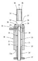
この実施例では、補助導体34は、外側導体21とネジ係合されることによって、放電管22の軸方向に沿ってスライド運動可能となっているが、例えば、図3に示されるように、補助導体34の外周面が、外側導体21の内周面に接触し、内周面が放電管22の外周面に接触するように構成することによって、補助導体34を、ネジ係合によらずにスライド運動可能とすることもできる。
In this embodiment, the
こうして、大気圧中において、同軸ケーブル24の他端に、(図示されない)マイクロ波発振器が接続され、マイクロ波発振器から所定の波長のマイクロ波が出力される。また、ガス導入管路32には、(図示されない)ガス供給源が接続される。そして、ガス供給源からガス導入管路32を通じて放電管22内にガスが導入されるとともに、マイクロ波発振器から出力されたマイクロ波が、同軸ケーブル24中を伝送され、同軸コネクタ27を介してアンテナ28に同軸モードで伝送される。そして、マイクロ波は、アンテナ28表面を伝わり、アンテナ28の先端で最も高い電界が生じ、プラズマがアンテナ28の先端と放電管22内壁との間において生成され、放電管22の先端開口から照射される。
Thus, in atmospheric pressure, a microwave oscillator (not shown) is connected to the other end of the
この実施例においても図1の実施例と同様の効果が得られ、特にこの実施例では、放電管22内にプラズマを維持することによって、長いプラズマを生成することができる。
In this embodiment, the same effect as that of the embodiment of FIG. 1 can be obtained. In particular, in this embodiment, a long plasma can be generated by maintaining the plasma in the
図4は、本発明のさらに別の好ましい実施例による同軸形マイクロ波プラズマトーチの側断面図である。図4に示した実施例は、図2の実施例と、基本的に、蓋の構成およびガス導入管路の構成が相違しているだけである。したがって、図4中、図2の構成要素と同一の構成要素には同一番号を付し、説明を省略する。
図3を参照して、トーチ本体20の40蓋は、円柱状の誘電体からなる、外側導体21内に挿入される差込部42と、差込部42の一端に設けられた導体からなるフランジ部41とから形成されている。そして、放電管22の一端は差込部42に固定されている。
FIG. 4 is a side sectional view of a coaxial microwave plasma torch according to still another preferred embodiment of the present invention. The embodiment shown in FIG. 4 is basically different from the embodiment of FIG. 2 only in the configuration of the lid and the configuration of the gas introduction conduit. Therefore, in FIG. 4, the same components as those of FIG.
With reference to FIG. 3, the 40 lid of the torch
この実施例では、ガス導入管路は、トーチ本体20の外側から、トーチ本体20の外側導体21を半径方向に貫通する電気絶縁性をもつ管部分43と、管部分43に接続され、蓋40の差込部42を半径方向に貫通する第1管路部分44と、第1管路部分44に接続され、アンテナ45内部を半径方向内側にのびた後、そこからアンテナ45内部をその先端に向かって軸方向にのび、当該先端に開口する第2管路部分45とからなっている。
In this embodiment, the gas introduction pipe is connected from the outside of the torch
こうして、この実施例では、アンテナ45の先端から放電管22内にガスが導入される。この実施例の場合にも、図2の実施例と同様の効果が得られる。
Thus, in this embodiment, gas is introduced into the
本発明によれば、大気圧中において、容易にプラズマを発生させることができる、非常に小型でエネルギー効率の高い同軸形マイクロ波プラズマトーチを提供することができる。そして、本発明によるマイクロ波プラズマトーチは、エッチング装置、CVD装置、表面処理装置、表面改質装置および材料改質装置等において、従来の導波管形マイクロ波プラズマトーチの代わりに使用することができる。 According to the present invention, it is possible to provide a very small and energy efficient coaxial microwave plasma torch capable of generating plasma easily under atmospheric pressure. The microwave plasma torch according to the present invention can be used in place of a conventional waveguide type microwave plasma torch in an etching apparatus, a CVD apparatus, a surface treatment apparatus, a surface modification apparatus and a material modification apparatus. it can.
1 外側導体
2 軸方向の孔
3 放電管
4 一端面
5 他端面
6 同軸ケーブル
7 外部導体
8 内部導体
9 アンテナ
10 同軸コネクタ
11 貫通孔
12 ボルト
13 ガス導入管路
14 円筒状のスペース
DESCRIPTION OF SYMBOLS 1
Claims (7)
前記外側導体の一端面側に形成された軸方向の孔に挿入され、固定された円筒状の放電管と、
一端が、外側から前記外側導体の他端面に取り付けられた、マイクロ波伝送用の同軸ケーブルと、を備え、
前記同軸ケーブルの一端には、その内部導体に電気的に接続されたアンテナが備えられ、前記外側導体には、その他端面側から前記軸方向の孔に向かって軸方向にのびる貫通孔が形成され、前記アンテナは、前記外側導体から電気的に絶縁された状態で前記貫通孔を通って前記放電管内にのび、前記同軸ケーブルの外部導体は前記外側導体に電気的に接続され、前記外側導体には、前記放電管内にガスを供給するガス導入管路が設けられていることを特徴とする同軸形マイクロ波プラズマトーチ。 An outer conductor having a cylindrical shape;
A cylindrical discharge tube inserted and fixed in an axial hole formed on one end surface side of the outer conductor;
A coaxial cable for microwave transmission, having one end attached to the other end surface of the outer conductor from the outside, and
One end of the coaxial cable is provided with an antenna electrically connected to the inner conductor, and the outer conductor is formed with a through hole extending in the axial direction from the other end surface side toward the axial hole. The antenna extends into the discharge tube through the through hole in a state of being electrically insulated from the outer conductor, and the outer conductor of the coaxial cable is electrically connected to the outer conductor, and is connected to the outer conductor. Is a coaxial microwave plasma torch characterized in that a gas introduction conduit for supplying gas into the discharge tube is provided.
前記トーチ本体の前記外側導体は、その一端開口を蓋によって閉じられ、前記放電管は、一端が前記蓋に固定され、他端が前記外側導体の他端開口から突出してのび、前記トーチ本体の前記外側導体の蓋には、外側から、マイクロ波伝送用の同軸ケーブルの一端が取り付けられ、前記同軸ケーブルの一端には、その内部導体に電気的に接続されたアンテナが備えられ、前記アンテナは、前記蓋から電気的に絶縁された状態で、前記蓋に形成された貫通孔を通って前記トーチ本体の前記放電管内に軸方向にのび、前記同軸ケーブルの外部導体は前記トーチ本体の前記外側導体に電気的に接続され、前記トーチ本体には、前記トーチ本体の前記放電管内にガスを供給するガス導入管路が設けられていることを特徴とする同軸形マイクロ波プラズマトーチ。 Comprising a torch body having a double tube structure consisting of a cylindrical outer conductor and a cylindrical discharge tube radially spaced inside thereof;
The outer conductor of the torch body is closed at one end opening by a lid, and the discharge tube has one end fixed to the lid and the other end protruding from the other end opening of the outer conductor, One end of a coaxial cable for microwave transmission is attached to the lid of the outer conductor from the outside, and one end of the coaxial cable is provided with an antenna electrically connected to the inner conductor. The outer conductor of the coaxial cable extends in the axial direction into the discharge tube of the torch body through a through hole formed in the lid while being electrically insulated from the lid. A coaxial microwave plasma characterized in that it is electrically connected to a conductor, and the torch body is provided with a gas introduction conduit for supplying gas into the discharge tube of the torch body. Over switch.
Priority Applications (7)
| Application Number | Priority Date | Filing Date | Title |
|---|---|---|---|
| JP2004105472A JP4109213B2 (en) | 2004-03-31 | 2004-03-31 | Coaxial microwave plasma torch |
| PCT/JP2005/005523 WO2005099322A1 (en) | 2004-03-31 | 2005-03-25 | Coaxial microwave plasma torch |
| EP05726969.8A EP1734798B1 (en) | 2004-03-31 | 2005-03-25 | Coaxial microwave plasma torch |
| KR1020067021870A KR20060134176A (en) | 2004-03-31 | 2005-03-25 | Coaxial Microwave Plasma Torch |
| CA2561657A CA2561657C (en) | 2004-03-31 | 2005-03-25 | Coaxial microwave plasma torch |
| CNA2005800103115A CN1954647A (en) | 2004-03-31 | 2005-03-25 | Coaxial microwave plasma torch |
| US10/594,746 US7858899B2 (en) | 2004-03-31 | 2005-03-25 | Coaxial microwave plasma torch |
Applications Claiming Priority (1)
| Application Number | Priority Date | Filing Date | Title |
|---|---|---|---|
| JP2004105472A JP4109213B2 (en) | 2004-03-31 | 2004-03-31 | Coaxial microwave plasma torch |
Publications (2)
| Publication Number | Publication Date |
|---|---|
| JP2005293955A true JP2005293955A (en) | 2005-10-20 |
| JP4109213B2 JP4109213B2 (en) | 2008-07-02 |
Family
ID=35125482
Family Applications (1)
| Application Number | Title | Priority Date | Filing Date |
|---|---|---|---|
| JP2004105472A Expired - Lifetime JP4109213B2 (en) | 2004-03-31 | 2004-03-31 | Coaxial microwave plasma torch |
Country Status (7)
| Country | Link |
|---|---|
| US (1) | US7858899B2 (en) |
| EP (1) | EP1734798B1 (en) |
| JP (1) | JP4109213B2 (en) |
| KR (1) | KR20060134176A (en) |
| CN (1) | CN1954647A (en) |
| CA (1) | CA2561657C (en) |
| WO (1) | WO2005099322A1 (en) |
Cited By (10)
| Publication number | Priority date | Publication date | Assignee | Title |
|---|---|---|---|---|
| JP2007157535A (en) * | 2005-12-06 | 2007-06-21 | Aet Inc | Traveling wave microwave plasma generating device |
| JP2009032545A (en) * | 2007-07-27 | 2009-02-12 | Md Luminous Kk | Microwave plasma needle generation device |
| JP2009070586A (en) * | 2007-09-10 | 2009-04-02 | Imagineering Kk | Plasma generation method, plasma generation apparatus, cavity for plasma generation apparatus, and measurement apparatus |
| JP2010056063A (en) * | 2008-08-26 | 2010-03-11 | Pohang Univ Of Science & Technology Academy-Industry Cooperation | Low power portable microwave plasma generator |
| CN102238794A (en) * | 2010-04-27 | 2011-11-09 | 嘉兴江林电子科技有限公司 | Contact-type plasma sparkpen |
| JP2012094367A (en) * | 2010-10-27 | 2012-05-17 | Ihi Corp | Plasma generating device |
| KR101830007B1 (en) * | 2016-11-11 | 2018-02-19 | 한국기초과학지원연구원 | COAXIAL CABLE COUPLED and WATER-COOLED TYPE SURFACE WAVE PLASMA GENERATING APPARATUS |
| CN109119314A (en) * | 2017-06-23 | 2019-01-01 | 日新离子机器株式会社 | plasma source |
| JP7475084B1 (en) | 2023-01-11 | 2024-04-26 | 株式会社アドテックプラズマテクノロジー | Coaxial microwave plasma torch |
| WO2024150695A1 (en) | 2023-01-11 | 2024-07-18 | 株式会社アドテックプラズマテクノロジー | Coaxial microwave plasma torch |
Families Citing this family (25)
| Publication number | Priority date | Publication date | Assignee | Title |
|---|---|---|---|---|
| US8800482B2 (en) * | 2005-12-29 | 2014-08-12 | Exatec Llc | Apparatus and method of dispensing conductive material with active Z-axis control |
| WO2008013112A1 (en) * | 2006-07-28 | 2008-01-31 | Tokyo Electron Limited | Microwave plasma source and plasma processing apparatus |
| EP2229282A1 (en) | 2007-12-31 | 2010-09-22 | Exatec, LLC. | Apparatus and method for printing three-dimensional articles |
| FR2952786B1 (en) * | 2009-11-17 | 2012-06-08 | Centre Nat Rech Scient | PLASMA TORCH AND METHOD OF STABILIZING A PLASMA TORCH |
| US10477665B2 (en) * | 2012-04-13 | 2019-11-12 | Amastan Technologies Inc. | Microwave plasma torch generating laminar flow for materials processing |
| KR101614028B1 (en) * | 2013-05-27 | 2016-04-20 | 가부시키가이샤 아도테쿠 프라즈마 테쿠노로지 | Cavity resonator of microwave plasma generating apparatus |
| PE20141732A1 (en) * | 2013-09-17 | 2014-11-30 | Amador Fernando Enrique Valencia | DIGESTION REACTOR BY ENERGY SUMP |
| US10167556B2 (en) * | 2014-03-14 | 2019-01-01 | The Board Of Trustees Of The University Of Illinois | Apparatus and method for depositing a coating on a substrate at atmospheric pressure |
| US9345121B2 (en) * | 2014-03-28 | 2016-05-17 | Agilent Technologies, Inc. | Waveguide-based apparatus for exciting and sustaining a plasma |
| CN105136749B (en) * | 2015-08-20 | 2017-12-22 | 浙江全世科技有限公司 | A kind of microwave plasma torch atomic emission spectrometer |
| ES2609511B1 (en) * | 2015-10-14 | 2018-01-24 | Universidad de Córdoba | DEVICE AND METHOD FOR SYNTHESIS OF GRAPHENE POWDER FROM A CARBON SOURCE |
| US10710313B2 (en) | 2016-11-07 | 2020-07-14 | Iftikhar Ahmad | Near-field microwave heating system and method |
| WO2018134502A1 (en) | 2017-01-23 | 2018-07-26 | Rhodia Operations | Method for producing a mixed oxide |
| EP3366647A1 (en) | 2017-02-23 | 2018-08-29 | Rhodia Operations | Plasma synthesis of particles comprising a chalcogenide comprising a rare earth element |
| DE202017103165U1 (en) | 2017-05-24 | 2017-06-22 | Leibniz-Institut für Oberflächenmodifizierung e.V. | Device for generating a plasma or radical beam |
| DE102017115438A1 (en) * | 2017-06-06 | 2018-12-06 | Fricke Und Mallah Microwave Technology Gmbh | DEVICE FOR GENERATING A PLASMASTRAEL IN THE MHZ AND GZ AREA WITH TEM AND HOLLOWING MODES |
| JP6579587B2 (en) * | 2017-09-20 | 2019-09-25 | 住友理工株式会社 | Plasma processing equipment |
| KR101930726B1 (en) * | 2017-09-27 | 2018-12-19 | 포항공과대학교 산학협력단 | Microwave Plasma Generator with Enhanced Power Transmission Efficiency |
| KR102722787B1 (en) * | 2017-12-04 | 2024-10-25 | 포항공과대학교 산학협력단 | Expansion method for sheath and bulk of microwave plasma induced by Radio Frequency bias |
| CN108449858A (en) * | 2018-05-18 | 2018-08-24 | 四川大学 | Plasma Jet Generator Based on Coaxial Structure and Terminal Compression |
| WO2022059247A1 (en) * | 2020-09-15 | 2022-03-24 | 株式会社島津製作所 | Radical generation device and ion analysis device |
| CN112996209B (en) * | 2021-05-07 | 2021-08-10 | 四川大学 | Structure and array structure for microwave excitation of atmospheric pressure plasma jet |
| CN113966062B (en) * | 2021-10-28 | 2025-02-14 | 重庆川仪自动化股份有限公司 | Plasma generating device and method |
| CN114189973B (en) * | 2021-12-09 | 2023-12-29 | 浙江大学湖州研究院 | Microwave plasma torch device with double microwave resonant cavities and application method thereof |
| CN116437551A (en) * | 2023-03-15 | 2023-07-14 | 安徽华东光电技术研究所有限公司 | Microwave plasma torch structure |
Family Cites Families (11)
| Publication number | Priority date | Publication date | Assignee | Title |
|---|---|---|---|---|
| FR2533397A2 (en) * | 1982-09-16 | 1984-03-23 | Anvar | IMPROVEMENTS IN PLASMA TORCHES |
| US5053678A (en) * | 1988-03-16 | 1991-10-01 | Hitachi, Ltd. | Microwave ion source |
| JPH03222298A (en) * | 1990-01-26 | 1991-10-01 | Hitachi Ltd | Microwave plasma ultratrace element analyzer |
| US5389153A (en) * | 1993-02-19 | 1995-02-14 | Texas Instruments Incorporated | Plasma processing system using surface wave plasma generating apparatus and method |
| JPH07321096A (en) * | 1994-05-20 | 1995-12-08 | Daihen Corp | Microwave plasma treating device |
| EP0727504A3 (en) * | 1995-02-14 | 1996-10-23 | Gen Electric | Plasma coating process for improved adhesive properties of coatings on objects |
| DE19814812C2 (en) * | 1998-04-02 | 2000-05-11 | Mut Mikrowellen Umwelt Technol | Plasma torch with a microwave transmitter |
| KR19990068381A (en) * | 1999-05-11 | 1999-09-06 | 허방욱 | microwave plasma burner |
| JP3687484B2 (en) * | 1999-06-16 | 2005-08-24 | 株式会社村田製作所 | Method for manufacturing ceramic substrate and unfired ceramic substrate |
| JP3497147B2 (en) * | 2001-09-19 | 2004-02-16 | 株式会社エー・イー・ティー・ジャパン | Ultra-small microwave electron source |
| JP4746844B2 (en) * | 2003-10-03 | 2011-08-10 | 三井化学株式会社 | Discharge plasma generation method and apparatus |
-
2004
- 2004-03-31 JP JP2004105472A patent/JP4109213B2/en not_active Expired - Lifetime
-
2005
- 2005-03-25 KR KR1020067021870A patent/KR20060134176A/en not_active Withdrawn
- 2005-03-25 CA CA2561657A patent/CA2561657C/en not_active Expired - Lifetime
- 2005-03-25 EP EP05726969.8A patent/EP1734798B1/en not_active Expired - Lifetime
- 2005-03-25 US US10/594,746 patent/US7858899B2/en active Active
- 2005-03-25 CN CNA2005800103115A patent/CN1954647A/en active Pending
- 2005-03-25 WO PCT/JP2005/005523 patent/WO2005099322A1/en not_active Ceased
Cited By (15)
| Publication number | Priority date | Publication date | Assignee | Title |
|---|---|---|---|---|
| JP2007157535A (en) * | 2005-12-06 | 2007-06-21 | Aet Inc | Traveling wave microwave plasma generating device |
| JP2009032545A (en) * | 2007-07-27 | 2009-02-12 | Md Luminous Kk | Microwave plasma needle generation device |
| JP2009070586A (en) * | 2007-09-10 | 2009-04-02 | Imagineering Kk | Plasma generation method, plasma generation apparatus, cavity for plasma generation apparatus, and measurement apparatus |
| JP2010056063A (en) * | 2008-08-26 | 2010-03-11 | Pohang Univ Of Science & Technology Academy-Industry Cooperation | Low power portable microwave plasma generator |
| CN102238794A (en) * | 2010-04-27 | 2011-11-09 | 嘉兴江林电子科技有限公司 | Contact-type plasma sparkpen |
| JP2012094367A (en) * | 2010-10-27 | 2012-05-17 | Ihi Corp | Plasma generating device |
| KR101830007B1 (en) * | 2016-11-11 | 2018-02-19 | 한국기초과학지원연구원 | COAXIAL CABLE COUPLED and WATER-COOLED TYPE SURFACE WAVE PLASMA GENERATING APPARATUS |
| CN109119314A (en) * | 2017-06-23 | 2019-01-01 | 日新离子机器株式会社 | plasma source |
| JP2019008965A (en) * | 2017-06-23 | 2019-01-17 | 日新イオン機器株式会社 | Plasma source |
| CN109119314B (en) * | 2017-06-23 | 2020-10-09 | 日新离子机器株式会社 | Plasma source |
| JP7475084B1 (en) | 2023-01-11 | 2024-04-26 | 株式会社アドテックプラズマテクノロジー | Coaxial microwave plasma torch |
| WO2024150695A1 (en) | 2023-01-11 | 2024-07-18 | 株式会社アドテックプラズマテクノロジー | Coaxial microwave plasma torch |
| WO2024150740A1 (en) * | 2023-01-11 | 2024-07-18 | 株式会社アドテックプラズマテクノロジー | Coaxial microwave plasma torch |
| KR20250108692A (en) | 2023-01-11 | 2025-07-15 | 가부시키가이샤 아도테쿠 프라즈마 테쿠노로지 | Coaxial Microwave Plasma Torch |
| EP4651630A1 (en) | 2023-01-11 | 2025-11-19 | ADTEC Plasma Technology Co., Ltd. | Coaxial microwave plasma torch |
Also Published As
| Publication number | Publication date |
|---|---|
| EP1734798A1 (en) | 2006-12-20 |
| KR20060134176A (en) | 2006-12-27 |
| CN1954647A (en) | 2007-04-25 |
| US20070210038A1 (en) | 2007-09-13 |
| EP1734798A4 (en) | 2009-07-29 |
| EP1734798B1 (en) | 2016-03-09 |
| CA2561657A1 (en) | 2005-10-20 |
| JP4109213B2 (en) | 2008-07-02 |
| WO2005099322A1 (en) | 2005-10-20 |
| US7858899B2 (en) | 2010-12-28 |
| CA2561657C (en) | 2014-07-29 |
Similar Documents
| Publication | Publication Date | Title |
|---|---|---|
| JP4109213B2 (en) | Coaxial microwave plasma torch | |
| JP5165678B2 (en) | lamp | |
| US4906898A (en) | Surface wave launchers to produce plasma columns and means for producing plasma of different shapes | |
| JP5533623B2 (en) | High frequency plasma ignition device | |
| JP2012526342A (en) | Microwave-driven light source | |
| RU2552107C2 (en) | Light source | |
| JP3149002B2 (en) | Coaxial microwave plasma generator | |
| US6191532B1 (en) | Arrangement for producing plasma | |
| WO2016084772A1 (en) | Ignition unit, ignition system, and internal combustion engine | |
| US6303007B1 (en) | Plasma injector | |
| JP4577684B2 (en) | Plasma generator and method for optimizing its power supply efficiency | |
| JP5493101B2 (en) | Microwave discharge lamp | |
| CN103967684A (en) | Corona ignition device | |
| US5065075A (en) | Launcher suitable for exciting surface waves in a discharge tube | |
| US20100074808A1 (en) | Plasma generating system | |
| JP4440371B2 (en) | Plasma generator | |
| WO2001078188A1 (en) | Reconfigurable plasma electromagnetic waveguide | |
| JP2015162267A (en) | Inductively-coupled micro plasma source with sealed floating electrode | |
| JP6677865B2 (en) | Ignition device | |
| JPWO2013035881A1 (en) | Antenna structure, high-frequency radiation plug, and internal combustion engine | |
| JP2004207011A (en) | Microwave heating device | |
| WO2016108283A1 (en) | Ignition system, and internal combustion engine | |
| JP6677867B2 (en) | Socket and spark plug | |
| WO2025074684A1 (en) | Ion source and ion gun | |
| JP2009181762A (en) | Microwave discharge lamp |
Legal Events
| Date | Code | Title | Description |
|---|---|---|---|
| A621 | Written request for application examination |
Free format text: JAPANESE INTERMEDIATE CODE: A621 Effective date: 20070305 |
|
| RD02 | Notification of acceptance of power of attorney |
Free format text: JAPANESE INTERMEDIATE CODE: A7422 Effective date: 20070305 |
|
| TRDD | Decision of grant or rejection written | ||
| A01 | Written decision to grant a patent or to grant a registration (utility model) |
Free format text: JAPANESE INTERMEDIATE CODE: A01 Effective date: 20080318 |
|
| A61 | First payment of annual fees (during grant procedure) |
Free format text: JAPANESE INTERMEDIATE CODE: A61 Effective date: 20080403 |
|
| FPAY | Renewal fee payment (event date is renewal date of database) |
Free format text: PAYMENT UNTIL: 20110411 Year of fee payment: 3 |
|
| R150 | Certificate of patent or registration of utility model |
Ref document number: 4109213 Country of ref document: JP Free format text: JAPANESE INTERMEDIATE CODE: R150 Free format text: JAPANESE INTERMEDIATE CODE: R150 |
|
| FPAY | Renewal fee payment (event date is renewal date of database) |
Free format text: PAYMENT UNTIL: 20120411 Year of fee payment: 4 |
|
| R250 | Receipt of annual fees |
Free format text: JAPANESE INTERMEDIATE CODE: R250 |
|
| FPAY | Renewal fee payment (event date is renewal date of database) |
Free format text: PAYMENT UNTIL: 20130411 Year of fee payment: 5 |
|
| R250 | Receipt of annual fees |
Free format text: JAPANESE INTERMEDIATE CODE: R250 |
|
| FPAY | Renewal fee payment (event date is renewal date of database) |
Free format text: PAYMENT UNTIL: 20140411 Year of fee payment: 6 |
|
| R250 | Receipt of annual fees |
Free format text: JAPANESE INTERMEDIATE CODE: R250 |
|
| R250 | Receipt of annual fees |
Free format text: JAPANESE INTERMEDIATE CODE: R250 |
|
| R250 | Receipt of annual fees |
Free format text: JAPANESE INTERMEDIATE CODE: R250 |
|
| R250 | Receipt of annual fees |
Free format text: JAPANESE INTERMEDIATE CODE: R250 |
|
| R250 | Receipt of annual fees |
Free format text: JAPANESE INTERMEDIATE CODE: R250 |
|
| R250 | Receipt of annual fees |
Free format text: JAPANESE INTERMEDIATE CODE: R250 |
|
| R250 | Receipt of annual fees |
Free format text: JAPANESE INTERMEDIATE CODE: R250 |
|
| R250 | Receipt of annual fees |
Free format text: JAPANESE INTERMEDIATE CODE: R250 |
|
| R250 | Receipt of annual fees |
Free format text: JAPANESE INTERMEDIATE CODE: R250 |
|
| R250 | Receipt of annual fees |
Free format text: JAPANESE INTERMEDIATE CODE: R250 |
|
| R250 | Receipt of annual fees |
Free format text: JAPANESE INTERMEDIATE CODE: R250 |
|
| EXPY | Cancellation because of completion of term |