JP2005293877A - Metal plate for fuel cell, separator for fuel cell using the same, and polymer electrolyte fuel cell using the same - Google Patents
Metal plate for fuel cell, separator for fuel cell using the same, and polymer electrolyte fuel cell using the same Download PDFInfo
- Publication number
- JP2005293877A JP2005293877A JP2004103088A JP2004103088A JP2005293877A JP 2005293877 A JP2005293877 A JP 2005293877A JP 2004103088 A JP2004103088 A JP 2004103088A JP 2004103088 A JP2004103088 A JP 2004103088A JP 2005293877 A JP2005293877 A JP 2005293877A
- Authority
- JP
- Japan
- Prior art keywords
- fuel cell
- metal
- separator
- metal plate
- noble metal
- Prior art date
- Legal status (The legal status is an assumption and is not a legal conclusion. Google has not performed a legal analysis and makes no representation as to the accuracy of the status listed.)
- Pending
Links
Images


Classifications
-
- Y—GENERAL TAGGING OF NEW TECHNOLOGICAL DEVELOPMENTS; GENERAL TAGGING OF CROSS-SECTIONAL TECHNOLOGIES SPANNING OVER SEVERAL SECTIONS OF THE IPC; TECHNICAL SUBJECTS COVERED BY FORMER USPC CROSS-REFERENCE ART COLLECTIONS [XRACs] AND DIGESTS
- Y02—TECHNOLOGIES OR APPLICATIONS FOR MITIGATION OR ADAPTATION AGAINST CLIMATE CHANGE
- Y02E—REDUCTION OF GREENHOUSE GAS [GHG] EMISSIONS, RELATED TO ENERGY GENERATION, TRANSMISSION OR DISTRIBUTION
- Y02E60/00—Enabling technologies; Technologies with a potential or indirect contribution to GHG emissions mitigation
- Y02E60/30—Hydrogen technology
- Y02E60/50—Fuel cells
Landscapes
- Electroplating Methods And Accessories (AREA)
- Fuel Cell (AREA)
Abstract
Description
本発明は、固体高分子形燃料電池のセパレータなどに用いる燃料電池用金属板およびこれを用いた上記燃料電池用セパレータならびにこれを用いた固体高分子形燃料電池に関する。 The present invention relates to a fuel cell metal plate used for a separator of a polymer electrolyte fuel cell, the fuel cell separator using the same, and a polymer electrolyte fuel cell using the same.
固体高分子形燃料電池用セパレータには、薄肉化と耐食性向上の観点から、ステンレス鋼などからなる金属薄板の表面と裏面との全面にAuなどの貴金属の薄膜を被覆し且つこれを圧延したものが提案されている(例えば、特許文献1参照)。しかしながら、上記金属薄板の全面にAuなどの貴金属をメッキなどにより被覆すると、コスト高になる、という問題がある。
一方、上記燃料電池用セパレータに隣接する電極などの他部材との接触電気抵抗を低減するため、係る他部材と接触する部分に厚み5nm以上の貴金属を付着させた低接触抵抗ステンレス鋼なども提案されている(例えば、特許文献2参照)。
Solid polymer electrolyte fuel cell separators are coated with a thin film of noble metal such as Au on the entire surface of the metal thin plate made of stainless steel, etc., and rolled from the viewpoint of thinning and improving corrosion resistance. Has been proposed (see, for example, Patent Document 1). However, if the entire surface of the metal thin plate is coated with a noble metal such as Au by plating or the like, there is a problem that the cost increases.
On the other hand, in order to reduce the contact electrical resistance with other members such as the electrode adjacent to the fuel cell separator, a low contact resistance stainless steel with a noble metal of 5 nm or more in contact with the other member is also proposed. (For example, refer to Patent Document 2).
しかしながら、前記特許文献2に記載の発明のように、セパレータにおける他部材と接触する部分にのみ貴金属を付着させることは、技術的に困難であると共に、製造コストも高くなる、という問題があった。
However, as in the invention described in
本発明は、前述した背景技術における問題点を解決し、金属基板に被覆する貴金属を低減し且つ接触電気抵抗も低減でき得ると共に、安価に供給し得る燃料電池のセパレータなどに用いる燃料電池用金属板、およびこれを用いた燃料電池用セパレータ、ならびにこれを用いた固体高分子形燃料電池を提供する、ことを課題とする。 MEANS TO SOLVE THE PROBLEM This invention solves the problem in background art mentioned above, can reduce the noble metal which coat | covers a metal substrate, can also reduce a contact electrical resistance, and is a metal for fuel cells used for the separator of the fuel cell etc. which can be supplied cheaply. It is an object of the present invention to provide a plate, a fuel cell separator using the same, and a solid polymer fuel cell using the same.
本発明は、前記課題を解決するため、金属基板に被覆すべきAuなどの貴金属の被覆パターンを最適化する、ことに着想して成されたものである。
即ち、本発明の燃料電池用金属板(請求項1)は、金属基板と、係る金属基板の表面および裏面の少なくとも一方に形成され且つ上記金属基板よりも貴な金属からなる複数の貴金属被覆部と、を備え、係る複数の貴金属被覆部は、上記金属基板の表面および裏面の少なくとも一方において、互いに離間し且つほぼ等間隔で位置している、ことを特徴とする。
In order to solve the above-mentioned problems, the present invention has been conceived by optimizing a coating pattern of a noble metal such as Au to be coated on a metal substrate.
That is, the metal plate for a fuel cell according to the present invention (Claim 1) is a metal substrate and a plurality of noble metal covering portions formed on at least one of the front and back surfaces of the metal substrate and made of a noble metal than the metal substrate. And the plurality of noble metal covering portions are spaced apart from each other and at substantially equal intervals on at least one of the front surface and the back surface of the metal substrate.
これによれば、複数の貴金属被覆部は、金属基板の表面や裏面において互いに離間し且つほぼ等間隔で位置しており、これらの間には金属基板の表面などが露出している。このため、個別の貴金属被覆部付近には、当該貴金属被覆部をカソード極とし且つその周囲に位置する金属基板の表面などをアノード極とする局部電池が形成される。この際、貴金属被覆部の貴金属は、アノード極である金属基板のアノード反応を促進させるような触媒的な作用を果たすため、アノード反応電流が大きくなる。一方、金属基板は、周囲からの酸化力を得て直ちに不動態膜を表・裏面に形成する。この結果、金属基板の電極電位が貴な方向に移動して、不動態電位域に保持されるため、燃料ガスや酸化剤ガスが流動するような腐食環境に置かれても、上記不動態膜によって露出している金属基板の腐食を抑制することが可能となる。
しかも、貴金属被覆部は、比較的少量の貴金属により形成でき、且つ電極などの他部材とも確実に接触し得る。このため、前記金属板を追って後述する燃料電池用セパレータに用いた場合、係るセパレータと他部材との接触電気抵抗を低減することも可能となる。更に、複数の貴金属被覆部は、互いに離間し且つほぼ等間隔で配置されるので、任意の配置模様で且つ少ない貴金属の使用量により形成し得るため、これを曲げ加工などして得られる上記セパレータのコストを更に低減することも容易となる。
According to this, the plurality of noble metal covering portions are spaced apart from each other on the front and back surfaces of the metal substrate and are located at substantially equal intervals, and the surface of the metal substrate is exposed between them. For this reason, a local battery is formed in the vicinity of the individual noble metal coating portion, with the noble metal coating portion serving as a cathode electrode and the surface of a metal substrate positioned around the noble metal coating portion as an anode electrode. At this time, the noble metal in the noble metal coating portion has a catalytic action that promotes the anode reaction of the metal substrate that is the anode electrode, so that the anode reaction current increases. On the other hand, the metal substrate immediately forms the passivation film on the front and back surfaces by obtaining the oxidizing power from the surroundings. As a result, the electrode potential of the metal substrate moves in a noble direction and is maintained in the passive potential range. Therefore, even when the fuel substrate is placed in a corrosive environment where the fuel gas or oxidant gas flows, It is possible to suppress corrosion of the exposed metal substrate.
In addition, the noble metal covering portion can be formed with a relatively small amount of noble metal and can reliably contact other members such as electrodes. For this reason, when the metal plate is used for a fuel cell separator to be described later, the contact electrical resistance between the separator and another member can be reduced. Further, since the plurality of noble metal coating portions are spaced apart from each other and arranged at almost equal intervals, the separator can be formed by bending or the like because it can be formed with an arbitrary arrangement pattern and a small amount of noble metal used. It is also easy to further reduce the cost.
但し、前記燃料電池用金属板は、固体高分子形燃料電池における集電板やコネクタなどにも使用することが可能である。
尚、前記金属基板は、ステンレス鋼板またはNi基合金板などからなる。また、前記貴金属被覆部は、Au、Ag、Pt、Pd、Ir、Rh、Ru、Osなどや、Au−Pt系、Au−Pd系、Au−Co系合金などからなり、パターンマスクを介した電解メッキ、無電解メッキ、スパッタリング、あるいはイオンプレーティグなどにより形成される。更に、前記複数の貴金属被覆部には、個別のサイズおよび形状が共通である他、互いに相似形である形態や、互いに形状が異なる形態も含まれる。尚また、前記複数の貴金属被覆部を前記金属基板の表面または裏面の一方に形成する形態は、いわゆる単層セルの燃料電池に活用できる。加えて、前記金属基板の表面と裏面とは、金属基板における一方の表面と他方の表面とを指し示す相対的な表現である。
However, the metal plate for a fuel cell can also be used for a current collector plate or a connector in a polymer electrolyte fuel cell.
The metal substrate is made of a stainless steel plate or a Ni-based alloy plate. The noble metal coating portion is made of Au, Ag, Pt, Pd, Ir, Rh, Ru, Os, or the like, or an Au—Pt series, Au—Pd series, Au—Co series alloy, etc. It is formed by electrolytic plating, electroless plating, sputtering, ion plating, or the like. Further, the plurality of noble metal covering portions include not only common sizes and shapes, but also shapes similar to each other and shapes different from each other. In addition, the form in which the plurality of noble metal coating portions are formed on one of the front surface and the back surface of the metal substrate can be utilized for a so-called single-layer cell fuel cell. In addition, the front surface and the back surface of the metal substrate are relative expressions indicating one surface and the other surface of the metal substrate.
また、本発明には、前記複数の貴金属被覆部は、前記金属基板の表面および裏面の双方に形成されていると共に、係る表面に形成された複数の貴金属被覆部と裏面に形成された複数の貴金属被覆部とは、上記金属基板の表面と裏面とにおいてほぼ同じ位置に分布しているか、あるいは、上記金属基板の表面と裏面とにおいて互いに異なるように互い違いの位置に分布している、燃料電池用金属板(請求項2)も含まれる。
これによれば、例えば、複数層の固体高分子膜を積層する燃料電池において、耐食性に優れ且つ電極などとの接触電気抵抗が低い燃料電池用セパレータを提供可能となると共に、固体高分子形燃料電池のコストを低減することにもできる。特に、複数の貴金属被覆部が金属基板の表面と裏面との互い違いの位置に分布する形態では、貴金属被覆部の面積割合を最小限にして、耐食性を確保することができる。
尚、複数の貴金属被覆部が金属基板の表面と裏面との同じ位置に分布する形態は、後述する「同相」として、複数の貴金属被覆部が金属基板の表面と裏面との互い違いの位置に分布する形態は、後述する「異相」として具体的に説明する。
In the present invention, the plurality of noble metal covering portions are formed on both the front surface and the back surface of the metal substrate, and the plurality of noble metal covering portions formed on the front surface and the plurality of noble metal covering portions formed on the back surface. The noble metal covering portion is distributed at substantially the same position on the front surface and the back surface of the metal substrate, or distributed at different positions so as to be different from each other on the front surface and the back surface of the metal substrate. Metal plates for use (claim 2) are also included.
According to this, for example, in a fuel cell in which a plurality of layers of solid polymer membranes are laminated, it is possible to provide a fuel cell separator having excellent corrosion resistance and low contact electric resistance with an electrode, etc., and solid polymer fuel The cost of the battery can also be reduced. In particular, in a form in which a plurality of noble metal coating portions are distributed at alternate positions between the front surface and the back surface of the metal substrate, the area ratio of the noble metal coating portions can be minimized to ensure corrosion resistance.
In addition, the form in which a plurality of noble metal coating portions are distributed at the same position on the front and back surfaces of the metal substrate is referred to as “in-phase” described later, and a plurality of noble metal coating portions are distributed at staggered positions on the front and back surfaces of the metal substrate. The form to be described will be specifically described as “different phase” to be described later.
更に、本発明には、前記金属基板の厚みは、1mm以下であると共に、前記貴金属被覆部の厚みは、1nm〜100nmの範囲にある、燃料電池用金属板(請求項3)も含まれる。これによれば、例えば、固体高分子形燃料電池全体の厚さを抑制した小型化が可能となり、且つこれに用いるセパレータと電極などとの接触電気抵抗を低減できると共に、上記燃料電池のコスト低減にも寄与し得る。
尚、金属基板の厚みが1mmを越えると、固体高分子形燃料電池全体の厚さが過大となってその小型化の支障になるため、係る範囲を除いた。望ましい金属基板の厚みは、0.1mm以下であるが、下限の厚みは実用面から約0.05mmである。また、金属被覆部の厚みが1nm未満になると、接触電気抵抗が無視できなくなり、一方、金属被覆部の厚みが100nmを越えると、コスト高になる。このため、これらの範囲を除去したものである。
Furthermore, the present invention includes a fuel cell metal plate (Claim 3) in which the thickness of the metal substrate is 1 mm or less and the thickness of the noble metal coating portion is in the range of 1 nm to 100 nm. According to this, for example, it is possible to reduce the size of the solid polymer fuel cell while suppressing the thickness of the whole, and it is possible to reduce the contact electric resistance between the separator and the electrode used for this, and to reduce the cost of the fuel cell. Can also contribute.
If the thickness of the metal substrate exceeds 1 mm, the thickness of the solid polymer fuel cell as a whole becomes excessive and hinders downsizing, so this range is excluded. The desirable thickness of the metal substrate is 0.1 mm or less, but the lower limit thickness is about 0.05 mm from the practical aspect. In addition, when the thickness of the metal coating portion is less than 1 nm, the contact electric resistance cannot be ignored. On the other hand, when the thickness of the metal coating portion exceeds 100 nm, the cost increases. For this reason, these ranges are removed.
また、本発明には、前記複数の貴金属被覆部は、前記金属基板の表面および裏面の少なくとも一方において、上記金属基板の厚み方向の視覚でそれぞれ直径0.05mm以上の円形、または少なくとも1辺の長さが0.05mm以上の四角形を呈すると共に、当該複数の貴金属被覆部の面積は、上記表面または裏面の面積の少なくとも10%を占めている、燃料電池用金属板(請求項4)も含まれる。
これによれば、例えば、耐食性の向上および接触電気抵抗の低減の双方が可能な燃料電池用セパレータなどを容易に提供することができる。
尚、上記四角形には、細長い縞状のストライプ(直線部)、長方形、正方形、平行四辺形、菱形が含まれる。また、上記直径または1辺の長さが0.05mm未満になり且つ上記面積が10%未満になると、隣接する電極などの他部材との接触面積が過少になり、係る他部材との接触電気抵抗が過大になり得るため、係る範囲を除外したものである。上記面積は、望ましくは20%以上である。
Further, according to the present invention, the plurality of noble metal covering portions each have a circular shape having a diameter of 0.05 mm or more, or at least one side, as viewed in the thickness direction of the metal substrate on at least one of the front surface and the back surface of the metal substrate. A fuel cell metal plate (Claim 4) including a square having a length of 0.05 mm or more and an area of the plurality of noble metal covering portions occupying at least 10% of the area of the front surface or the back surface is included. It is.
According to this, for example, it is possible to easily provide a fuel cell separator capable of both improving corrosion resistance and reducing contact electric resistance.
The quadrangle includes elongated striped stripes (straight line portions), rectangles, squares, parallelograms, and rhombuses. Further, when the diameter or the length of one side is less than 0.05 mm and the area is less than 10%, the contact area with another member such as an adjacent electrode becomes too small, and the contact electricity with the other member becomes smaller. This range is excluded because the resistance can be excessive. The area is desirably 20% or more.
更に、本発明には、前記金属基板の表面および裏面の少なくとも一方において、前記円形または四角形を呈すると共に、互いに隣接する最短距離にある一対の貴金属被覆部間の距離(s,s′)は、個々の貴金属被覆部の直径または一辺の長さ(d)の0.1〜5倍の範囲である、燃料電池用金属板(請求項5)も含まれる。
これによれば、例えば、個別の貴金属被覆部をカソード極とし且つその周囲に位置する金属基板をアノード極とする局部電池を形成できると共に、直ぐにアノード極である当該金属基板の表・裏面に不動態膜を形成できるため、不動態電位域に至らぬ金属基板の表・裏面部分を容易に解消できる。このため、燃料電池用セパレータなどの耐食性を確保することが容易となる。尚、同じ燃料電池用金属板に円形と四角形の貴金属被覆部を混在させても良い。
Furthermore, in the present invention, the distance (s, s ′) between a pair of noble metal covering portions which are the circular or quadrangular shape and which are adjacent to each other at the shortest distance on at least one of the front surface and the back surface of the metal substrate is: Also included is a metal plate for a fuel cell (Claim 5) which is in the range of 0.1 to 5 times the diameter or length (d) of each noble metal coating portion.
According to this, for example, it is possible to form a local battery having an individual noble metal coating portion as a cathode electrode and a metal substrate positioned around the noble metal coating portion as an anode electrode. Since a dynamic film can be formed, the front and back portions of the metal substrate that do not reach the passive potential range can be easily eliminated. For this reason, it becomes easy to ensure corrosion resistance, such as a separator for fuel cells. In addition, you may mix a circular and square noble metal coating | coated part in the same metal plate for fuel cells.
また、本発明には、前記金属被覆部は、前記金属基板の厚み方向の視覚で、円形、長円形、楕円形、正三角形以上の正多角形、変形多角形、長方形、台形、平行四辺形、ほぼY字形、ほぼ十字形、ほぼ星形、または異形形状を呈する、燃料電池用金属板(請求項6)も含まれる。
これによれば、金属基板の表面などに複数の金属被覆部を多様な形状で配設したセパレータなどに用いる金属板が得られるため、所要の特性やサイズに応じた固体高分子形燃料電池、集電板、またはコネクタを提供することが可能となる。
尚、上記各形状は、例えば上記形状のパターン孔を有するフッ素樹脂(登録商標:テフロン)またはエポキシ樹脂などをフィルム状にし且つ所要形状のパターン孔を有する絶縁性マスク材を用い、これを金属基板に密着させつつメッキを施すことで得られる。また、上記異形形状とは、不規則な外形を有する全ての形状を指す。尚また、上記各形状の金属被覆部を同じ燃料電池用金属板に混在させても良い。
Further, according to the present invention, the metal covering portion is a circle, an oval, an ellipse, a regular polygon greater than or equal to a regular triangle, a deformed polygon, a rectangle, a trapezoid, and a parallelogram, as viewed in the thickness direction of the metal substrate. Also included is a metal plate for a fuel cell (Claim 6) having a substantially Y shape, a substantially cross shape, a substantially star shape, or an irregular shape.
According to this, since a metal plate used for a separator having a plurality of metal coating portions arranged in various shapes on the surface of a metal substrate or the like can be obtained, a solid polymer fuel cell according to required characteristics and size, A current collector plate or a connector can be provided.
In addition, each said shape uses the insulating mask material which forms the film shape and has a pattern hole of a required shape, for example, using a fluororesin (trademark: Teflon) or an epoxy resin etc. which have the pattern hole of the said shape, and this is made into a metal substrate It can be obtained by plating while closely contacting. The irregular shape refers to all shapes having an irregular outer shape. In addition, the metal coating portions of the above shapes may be mixed in the same fuel cell metal plate.
更に、本発明には、前記複数の貴金属被覆部は、前記金属基板の表面および裏面の少なくとも一方において、上記金属基板の厚み方向の視覚で、複数の直線部からなる縞模様を呈するか、あるいは、それぞれが交点または交互に位置する格子模様または千鳥模様を呈する、燃料電池用金属板(請求項7)も含まれる。
これによれば、例えば、前記局部電池を多数形成することが容易にできると共に、少量の貴金属により不動態電位域に至らぬ金属基板の部分を確実に解消できる。このため、燃料電池用セパレータの耐食性を確保でき且つ接触電気抵抗の低減も容易となる。
Further, according to the present invention, the plurality of noble metal covering portions have a striped pattern composed of a plurality of linear portions visually in the thickness direction of the metal substrate on at least one of the front surface and the back surface of the metal substrate, or Also included is a metal plate for a fuel cell (Claim 7), each of which exhibits a lattice pattern or a staggered pattern that are located at intersections or alternately.
According to this, for example, it is possible to easily form a large number of the local batteries, and it is possible to reliably eliminate the portion of the metal substrate that does not reach the passive potential region with a small amount of noble metal. For this reason, the corrosion resistance of the fuel cell separator can be ensured, and the contact electrical resistance can be easily reduced.
また、本発明には、複数の貴金属被覆部を形成した前記金属基板の表面および裏面の少なくとも一方に、カーボンの薄膜が更に被覆されている、燃料電池用金属板(請求項8)も含まれる。
これによれば、複数の貴金属被覆部により金属基板の腐食を防止すると共に、貴金属被覆部または上記カーボンの薄膜の少なくとも一方により、隣接する電極との間における接触電気抵抗を低減することが可能となる。
尚、上記カーボンの薄膜には、厚みが3〜100μmのカーボン塗料の塗膜または50〜500μmの膨張黒鉛が用いられ、その特性上から15〜50μmの厚みが推奨される。上記薄膜の厚みが厚みが3μm未満になると、接触電気抵抗が無視できなくなり、500μmを越えると、導電性の効果が飽和し且つ上記金属板が厚くなり過ぎるためである。
The present invention also includes a fuel cell metal plate (Claim 8) in which at least one of the front surface and the back surface of the metal substrate on which a plurality of noble metal coating portions are formed is further coated with a carbon thin film. .
According to this, it is possible to prevent the metal substrate from being corroded by the plurality of noble metal coating portions and to reduce the contact electric resistance between adjacent electrodes by at least one of the noble metal coating portion or the carbon thin film. Become.
For the carbon thin film, a coating film of carbon paint having a thickness of 3 to 100 μm or expanded graphite having a thickness of 50 to 500 μm is used, and a thickness of 15 to 50 μm is recommended because of its characteristics. If the thickness of the thin film is less than 3 μm, the contact electric resistance cannot be ignored, and if it exceeds 500 μm, the conductive effect is saturated and the metal plate becomes too thick.
一方、本発明の第1の燃料電池用セパレータ(請求項9)は、前記燃料電池用金属板からなるセパレータ用金属板と、係るセパレータ用金属板に設けられ、表面および裏面の一方が凸条で且つ他方が凹溝となる複数の平行な凹凸部とを備え、少なくとも凹凸部の凸条の頂き面および凹溝の底面に前記複数の貴金属被覆が位置している、ことを特徴とする。
これによれば、凸条の頂き面に位置する貴金属被覆は、耐食性の向上と接触電気抵抗の低減との双方に寄与し、且つ凹溝の底面に位置する貴金属被覆は、セパレータ自体の耐食性の向上に寄与できる。従って、耐食性が高く且つ接触電気抵抗の低い固体高分子形燃料電池を提供することが可能となる。
On the other hand, a first fuel cell separator of the present invention (Claim 9) is provided on the separator metal plate made of the fuel cell metal plate and the separator metal plate, and one of the front and back surfaces is convex. And a plurality of parallel concavo-convex portions, the other of which is a concave groove, wherein the plurality of noble metal coatings are located at least on the crest surface of the ridge and the bottom surface of the concave groove.
According to this, the noble metal coating located on the ridge surface of the ridge contributes to both the improvement of corrosion resistance and the reduction of the contact electrical resistance, and the noble metal coating located on the bottom surface of the groove has the corrosion resistance of the separator itself. It can contribute to improvement. Therefore, it is possible to provide a polymer electrolyte fuel cell having high corrosion resistance and low contact electric resistance.
また、本発明の第2の燃料電池用セパレータ(請求項10)は、前記燃料電池用金属板からなるセパレータ用金属板と、係るセパレータ用金属板の表面および裏面の少なくとも一方に形成したカーボンからなる複数の棒材と、係る複数の棒材間の凹溝の底面に前記複数の貴金属被覆部が位置している、ことを特徴とする。これによれば、カーボンからなる平行な複数の棒材により、それらの間に燃料ガスや酸化剤ガスの流路となる凹溝が形成され、当該棒材の頂き面で隣接する電極などとの間における接触電気抵抗を低減できる。しかも、各凹溝の底面に位置している複数の貴金属被覆部により、セパレータ自体の腐食を確実に防止することができる。尚、上記カーボンの棒材は、カーボン塗料の塗膜、膨張黒鉛、またはカーボン不織布などにより形成される。 A second fuel cell separator according to the present invention (Claim 10) comprises a separator metal plate made of the fuel cell metal plate and carbon formed on at least one of the front and back surfaces of the separator metal plate. The plurality of noble metal covering portions are located on the bottom surfaces of the plurality of bars and the groove between the plurality of bars. According to this, a plurality of parallel bar members made of carbon form a concave groove serving as a flow path for the fuel gas or oxidant gas between them, and with the adjacent electrodes on the surface of the bar member. It is possible to reduce the contact electrical resistance between the two. In addition, corrosion of the separator itself can be reliably prevented by the plurality of noble metal coating portions positioned on the bottom surface of each concave groove. The carbon bar is formed of a carbon coating film, expanded graphite, carbon non-woven fabric, or the like.
更に、本発明には、前記複数の貴金属被覆の全面積は、前記セパレータ用金属板の表面または裏面の面積の少なくとも10%を占めている、燃料電池用セパレータ(請求項11)も含まれる。
これによれば、耐食性の向上および接触電気抵抗の低減の双方が可能な燃料電池用セパレータとなるため、前記のような優れた燃料電池を提供可能となる。
尚、上記面積割合(面積率)は、望ましくは20%またはこれ以上である。
加えて、本発明の固体高分子形燃料電池(請求項12)は、複数の前記燃料電池用セパレータと、係る複数の燃料電池用セパレータの間に位置する固体高分子膜と、を含む、ことを特徴とする。尚、固体高分子膜は、単数でも複数でも良い。
これによれば、耐食性に優れ且つ電流が流れ易くて効率の良い固体高分子形燃料電池を安価に提供することが可能となる。
Furthermore, the present invention includes a fuel cell separator (Claim 11) in which the total area of the plurality of noble metal coatings occupies at least 10% of the area of the front surface or the back surface of the separator metal plate.
According to this, since it becomes the separator for fuel cells in which both improvement of corrosion resistance and reduction of contact electric resistance are possible, it becomes possible to provide the excellent fuel cell as described above.
The area ratio (area ratio) is desirably 20% or more.
In addition, the solid polymer fuel cell of the present invention (Claim 12) includes a plurality of the fuel cell separators and a solid polymer membrane positioned between the plurality of fuel cell separators. It is characterized by. The solid polymer film may be singular or plural.
According to this, it is possible to provide an inexpensive polymer electrolyte fuel cell that is excellent in corrosion resistance and that allows current to flow easily.
以下において、本発明を実施するための最良の形態について説明する。
図1は、本発明における一形態の燃料電池のセパレータに用いる燃料電池用金属板(以下、単にセパレータ用金属板と記する)1を示す正面図、図2は、係るセパレータ用金属板1の断面図、図3は図2中の部分拡大図である。
セパレータ用金属板1は、図1,2に示すように、表面3および裏面4を有する金属基板2と、係る表面3に形成した複数の貴金属被覆部5と、係る裏面4に形成した複数の貴金属被覆部6とを備えている。
金属基板2は、厚みが1mm以下のステンレス鋼(例えば、SUS316L)からなる。また、貴金属被覆部5,6は、金属基板2よりも腐食電位が貴な金属、例えばAuからなり、直径(d):0.05mm以上で且つ厚み:1nm〜100nmである。尚、貴金属被覆部5,6は、円形を呈する多数のパターン孔を穿孔したフッ素樹脂またはエポキシ樹脂などをフィルム状にし且つ所要形状のパターン孔を有する絶縁性マスク材を金属基板2に密着させた状態で、Auを電解メッキ、無電解メッキ、スパッタリング、あるいはイオンプレーティングなどすることで形成されている。
In the following, the best mode for carrying out the present invention will be described.
FIG. 1 is a front view showing a fuel cell metal plate (hereinafter simply referred to as a separator metal plate) 1 used for a separator of a fuel cell according to one embodiment of the present invention, and FIG. Sectional drawing and FIG. 3 are the elements on larger scale in FIG.
As shown in FIGS. 1 and 2, the
The
複数の貴金属被覆部5,6は、図1,2に示すように、表面3および裏面4において、互いに離間し且つ等間隔で位置するように、表面3および裏面4の各辺と平行な複数の長方形からなる格子模様の交点に位置に分布している。また、複数の貴金属被覆部5,6は、表面3または裏面4の面積全体の10%以上を占めている。しかも、複数の貴金属被覆部5,6は、図1〜3に示すように、表面3および裏面4において、互い違い(異相)の位置に分布して形成されている。
図3に示すように、表面3または裏面4、あるいは表・裏面3,4間において互いに隣接し且つ最短距離にある貴金属被覆部5,5間の距離(s,s′)は、前記直径(d)の0.1〜5倍の範囲に設定されている。
As shown in FIGS. 1 and 2, the plurality of noble
As shown in FIG. 3, the distance (s, s ′) between the noble
図4は、異なる形態のセパレータ用金属板1aの正面図を示す。係るセパレータ用金属板1aも、前記同様の金属基板2と、その表面3に形成した複数の貴金属被覆部5と、裏面4に形成した複数の貴金属被覆部6とを備えている。
複数の貴金属被覆部5,6も、Auからなり、図4に示すように、表面3および裏面4において、互いに離間し且つ等間隔で位置するように、表面3および裏面4の各辺に対し斜め姿勢の四角形の交点に位置し且つ千鳥模様を呈すると共に、表面3または裏面4の面積全体の10%以上を占めている。しかも、複数の貴金属被覆部5,6は、図4に示すように、表面3および裏面4において、互い違い(異相)の位置に分布するように形成されている。
FIG. 4 shows a front view of the separator metal plate 1a in a different form. The separator metal plate 1 a also includes the
The plurality of noble
図5は、更に異なる形態のセパレータ用金属板1bの部分正面図を示し、前記同様の金属基板2と、その表面3に形成した複数の貴金属被覆部5と、裏面4に形成した複数の貴金属被覆部6とを備えている。
複数の貴金属被覆部5,6も、Auからなり、図5に示すように、表面3および裏面4において、互いに離間し且つほぼ等間隔で位置し、且つ千鳥模様を呈するように分布すると共に、表面3または裏面4の面積全体の10%以上を占めている。但し、貴金属被覆部5は、反対側の裏面4における三角形の交点に位置する3個の貴金属被覆部6に囲まれ、貴金属被覆部6は、反対側の表面3における上記3個の貴金属被覆部5に囲まれている。即ち、貴金属被覆部5,6もほぼ互い違い(異相)の位置に分布して形成されている。
FIG. 5 shows a partial front view of a
The plurality of noble
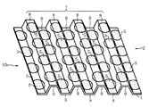
図6は、前記セパレータ用金属板1を折り曲げ加工またはプレス加工して得た本発明の第1の燃料電池用セパレータ(以下、単にセパレータと記する)10aの要部を示す斜視図である。係るセパレータ10aは、前記同様の金属基板2と、その表面3および裏面4の一方が凸条8で且つ他方が凹溝9となる組を平行に複数有する凹凸部7を備えている。しかも、複数の貴金属被覆部5,6は、凸条8の頂き面や凹溝9の底面において、それらの長手方向に沿って等間隔に位置し、且つ凸条8の頂き面と凹溝9の底面との間でも等間隔に位置している。
凸条8および凹溝9は、断面台形を呈し、図6に示すように、金属基板2の表面3と裏面4とに裏腹の関係で成形されると共に、隣接する凸条8および凹溝9と互いに平行に位置している。
FIG. 6 is a perspective view showing a main part of a first fuel cell separator (hereinafter simply referred to as a separator) 10a of the present invention obtained by bending or pressing the
The
例えば、凸条8の頂き面は、金属基板2の表面3または裏面4の面積全体の約10%であり、当該凸条8の頂き面を後述する固体高分子形燃料電池の電極と接する面とした場合、係る電極との接触電気抵抗を低減して良好な電気的導通を得るには、表面3または裏面4における凸条8の頂き面の面積における10%以上を貴金属被覆部5,6を被覆することが必要である。
換言すれば、前記セパレータ用金属板1において、その表面3または裏面4の面積全体の10%以上を貴金属被覆部5,6を被覆する必要である。この点に関しては、前記セパレータ用金属板1a,1bも同じである。
For example, the crest surface of the
In other words, in the
以上のような凹凸部7の当該凸条8の頂き面および凹溝9の底面に複数の貴金属被覆部5,6を等間隔に被覆したセパレータ10aによれば、各貴金属被覆部5,6とこれに隣接する金属基板2の表面3または裏面4との間で局部電池が形成される。一般に、不動態皮膜を表・裏面に形成しない金属基板2を用いた場合は、係る局部電池によって腐食される。しかし、ステンレス鋼からなる金属基板2を用いた場合は、逆に局部電池が不動態化を促進するので、貴金属被覆部5,6がない表面3および裏面4に形成されるクロム酸化物(CrOOH)の不動態皮膜は、不動態電位域にシフトして強固に形成される。このため、燃料ガスまたは酸化剤ガスが凹溝9内を流動しても露出している金属基板2の腐食を抑制できる。
しかも、凸条8の頂き面には、その10%以上の面積率で複数の貴金属被覆部5,6が位置しているため、燃料電池の電極との接触電気抵抗を抑制し良好な導通を確保できる。従って、セパレータ10aによれば、耐食性に優れ且つ接触電気抵抗を低減した安価な固体高分子形燃料電池を提供することが可能になる。
According to the
Moreover, since the plurality of noble
図7は、前記セパレータ用金属板1a,1bを折り曲げ加工またはプレス加工して得たセパレータ10bの要部を示す斜視図である。係るセパレータ10aも、前記同様の金属基板2と、その表面3および裏面4の一方が凸条8で且つ他方が凹溝9となる組を平行に複数有する凹凸部7を備え、且つこれら凸条8および凹溝9は、裏腹の関係で成形されると共に、隣接する凸条8および凹溝9と互いに平行に位置している。更に、複数の貴金属被覆部5,6は、凸条8の頂き面や凹溝9の底面において、それらの長手方向に沿って等間隔に位置し、且つ凸条8の頂き面と凹溝9の底面との間では等間隔またはほぼ等間隔に位置している。尚、複数の貴金属被覆部5,6の面積割合は、前記セパレータ10aと同様である。
以上のようなセパレータ10bによっても、前記セパレータ10aと同様な効果が得られる。
FIG. 7 is a perspective view showing a main part of a
The effect similar to that of the
図8は、別形態のセパレータ用金属板1cの正面図、図9は、係る金属板1cを折り曲げまたはプレス加工して得たセパレータ10cの要部を示す斜視図である。セパレータ用金属板1cは、図8に示すように、表面3および裏面4を有する前記同様の金属基板2と、その表面3において対向する図示で上辺と下辺とに平行な細長い長方形(直線部)からなる複数の貴金属被覆部11と、金属基板2の裏面4において上記同様に位置し且つ表面3に形成される貴金属被覆部11,11の中間に位置するよう互い違い(異相)に分布した複数の細長い長方形の貴金属被覆部12を備えている。
貴金属被覆部11,12の幅(一辺の長さ)dは、0.05mm以上でそれらの厚みは前記と同じであると共に、係る貴金属被覆部11,12もAuからなり、表面3または裏面4において10%以上の面積を占めている。
即ち、複数の貴金属被覆部11,12は、表面3または裏面4において縞模様を呈すると共に、金属基板2の表面3と裏面4において、互い違い(異相)の位置に分布して形成されている。しかも、表面3と裏面4との間で隣接する貴金属被覆部11,12間の距離(s′)は、上記幅(d)の0.1〜5倍である。
FIG. 8 is a front view of another embodiment of the separator metal plate 1c, and FIG. 9 is a perspective view showing a main part of the
The width (length of one side) d of the noble
That is, the plurality of noble
前記セパレータ用金属板1cを、複数の貴金属被覆部11,12の長手方向と直交する方向に沿って、折り曲げ加工またはプレス加工することで、図9に要部を示すセパレータ10cが得られる。即ち、セパレータ10cは、図9に示すように、前記金属基板2と、その表面3および裏面4の一方が凸条8で且つ他方が凹溝9となる組を平行に複数有する凹凸部7を備えている。しかも、複数の貴金属被覆部11,12は、凸条8の頂き面、凹溝9の底面、およびこれらの間の傾斜した側面において、それらの長手方向に沿って等間隔に位置すると共に、凸条8の頂き面、凹溝9の底面、およびこれらの間の傾斜した側面の長手方向と直交する方向に沿って等間隔に位置している。尚、凸条8および凹溝9は、断面台形を呈し、図9に示すように、金属基板2の表面3と裏面4とに裏腹の関係で成形され、且つ隣接する凸条8および凹溝9と互いに平行に位置している。
9 is obtained by bending or pressing the separator metal plate 1c along a direction perpendicular to the longitudinal direction of the plurality of noble
以上のセパレータ10cによれば、個別の貴金属被覆部11,12とこれに隣接する金属基板2の表面3または裏面4との間で局部電池が形成されるため、表面3および裏面4に当初から形成されているクロム酸化物(CrOOH)からなる不動態膜は、不動態域にシフトする。この結果、燃料ガスまたは酸化剤ガスが凹溝9内を流動しても露出している金属基板2の腐食を抑制することができる。
しかも、凸条8の頂き面には、その10%以上の面積率で複数の貴金属被覆部11,12が占めているため、燃料電池の電極との接触電気抵抗を低減し良好な導通性を確保できる。従って、セパレータ10cによっても、耐食性に優れ且つ接触電気抵抗を低減した安価な固体高分子形燃料電池を提供することができる。
According to the
In addition, since the plurality of noble
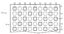
図10は、更に別形態のセパレータ用金属板1dの部分正面図である。係るセパレータ用金属板1dは、前記金属基板2と、その表面3に形成した複数の貴金属被覆部13と、裏面4に形成した複数の貴金属被覆部14とを備えている。貴金属被覆部13,14もAuからなり、四つの出隅部をアールとしたほぼ正方形を呈し、金属基板2の表面3または裏面4において互いに離間し且つ等間隔で位置するように、表面3と裏面4の各辺に平行な複数の四角形からなる格子模様の交点の位置に互い違い(異相)に分布している。
貴金属被覆部13,14は、四つの出隅部が直角の正方形と仮定した際の一辺の長さ(d)が0.05mm以上で、前記同様の厚みと面積率とを備えている。また、表面3と裏面4との間で隣接する貴金属被覆部13,14間の距離(s′)は、上記長さ(d)の0.1〜5倍である。
FIG. 10 is a partial front view of a separator metal plate 1d according to another embodiment. The separator metal plate 1 d includes the
The noble
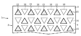
図11は、別個の形態のセパレータ用金属板1eを示す部分正面図で、前記金属基板2と、その表面3に形成した複数の貴金属被覆部15と、裏面4に形成した複数の貴金属被覆部16とを備えている。貴金属被覆部15,16もAuからなり、正三角形を呈すると共に、金属基板2の表面3または裏面4において互いに離間し且つ等間隔で位置するように分布している。また、貴金属被覆部15,16は、表面3および裏面4において、互い違い(異相)の位置に形成され、且つ前記同様の厚みと面積率とを具備している。
FIG. 11 is a partial front view showing a metal plate 1e for a separator in a separate form. The
図12は、更に別個の形態のセパレータ用金属板1fを示す部分正面図で、前記金属基板2と、その表面3に形成した複数の貴金属被覆部17と、裏面4に形成した複数の貴金属被覆部18とを備えている。貴金属被覆部17,18もAuからなり、平行四辺形(菱形)を呈すると共に、金属基板2の表面3または裏面4において互いに離間し且つ等間隔で位置するように分布している。また、貴金属被覆部17,18は、表面3および裏面4において、互い違い(異相)の位置に形成され、且つ前記同様の厚みと面積率とを具備している。
以上のようなセパレータ用金属板1d〜1fを折り曲げ加工またはプレス加工して得られる前記凹凸部7を有するセパレータ(図示せず)によっても、前記セパレータ10a〜10cと同様な効果を得ることが可能である。
FIG. 12 is a partial front view showing a separate metal plate for separator 1f. The
Effects similar to those of the
図13は、前記セパレータ10a〜10cを用いた本発明の固体高分子形燃料電池(以下、単に燃料電池と記する)20の概略断面を示す。係る燃料電池20は、図13で例示するように、複数のセパレータ10cと、これらの間に個別に位置する固体高分子膜23を含むセル本体22とを備えている。セル本体22は、固体高分子膜23の両面に互いに異極で且つガス拡散層と触媒層を含む電極24,26を積層したものである。尚、固体高分子膜23は、例えばスルホン酸基を含むフッ素樹脂からなる。
燃料電池20では、セル本体22の一方の電極24に開口するセパレータ10cの凹溝9に燃料ガス(例えば、水素)が流され、他方の電極26に開口するセパレータ10cの凹溝9に酸化剤ガス(例えば、空気)が流される。上記燃料ガスがアノード電極24に接触すると、当該水素が水素イオンと電子とに分解する。係る電子は、図示しない外部回路を経て、カソード電極26に送られる。係る外部回路を流れる電流により、発電が生じる。
FIG. 13 shows a schematic cross section of a polymer electrolyte fuel cell (hereinafter simply referred to as a fuel cell) 20 of the present invention using the
In the
一方、上記酸化剤ガスがカソード電極26に接触すると、予め含有している酸素と、固体高分子膜23を貫通した水素イオンと、迂回した電子とが反応して水が形成される。この間において、セパレータ10cは、電極24,26に面接触する凸条8の頂き面の貴金属被覆部11,12が当該電極24,26との接触電気抵抗を低減すると共に、その他の部位の貴金属被覆部11,12を含めて、酸化剤ガスによる腐食から当該セパレータ10cの腐食を防止する。
従って、複数のセル本体22の間およびその最上面および最下面にセパレータ10cを個別に配置した燃料電池20によれば、耐食性に優れ且つ接触電気抵抗が低く良好な導通性が得られるため、耐久性と発電効率とが高められる。
尚、前記セパレータ10a,10bや、前記セパレータ用金属板1d〜1fを加工したセパレータを燃料電池20に適用しても同様の効果が得られる。
On the other hand, when the oxidant gas comes into contact with the
Therefore, according to the
The same effect can be obtained even when the
以下において、本発明のセパレータ用金属板の具体的な実施例を説明する。
ステンレス鋼(SUS316L)からなり、40mm×50mmで且つ表1に示す厚みの金属基板2を複数枚用意した。このうちの1枚(比較例1)を除き、各金属基板2の表面3および裏面4の少なくとも一方に、Auメッキ(貴金属被覆部)を表1に示す形状、寸法、厚み、配置模様、隣接する最短距離(s,s′)、メッキ面、および同相または異相に分けて形成した。これらを実施例1〜11、または比較例1〜3のセパレータ用金属板とした。
尚、上記同相とは、表面3および裏面4の同じ位置にAuメッキが形成される形態を、上記異相とは、前述した互い違いの配置となる形態を指す。このため、異相における最短距離は、前記図3で示した表・裏面3,4間の距離s′となる。また、Auメッキに覆われていない表面3や裏面4の露出割合も表1に示した。
各例のセパレータ用金属板について、濃度1wt%の沸騰硫酸液中に168時間にわたり浸漬した後、取り出して外観の変色、Auメッキ膜の剥離の有無を観察した。また、浸漬後の腐食液に対し、ICP分析して溶出した金属イオンを測定して、各例の腐食度を得た。それらの結果も表1に示した。
Below, the specific Example of the metal plate for separators of this invention is described.
A plurality of
In addition, the said in-phase refers to the form in which Au plating is formed at the same position on the
The separator metal plate of each example was immersed in boiling sulfuric acid solution having a concentration of 1 wt% for 168 hours and then taken out and observed for discoloration of the appearance and peeling of the Au plating film. Moreover, the metal ion eluted by ICP analysis was measured for the corroded liquid after immersion, and the corrosion degree of each example was obtained. The results are also shown in Table 1.

表1によれば、実施例1〜11のセパレータ用金属板は、腐食度(mm/y)が3.17×10−2以下と小さいと共に、外観の変色やAuメッキ膜の剥離も生じていなかった。特に、実施例1などのように、金属基板の表・裏面が88%露出していても、十分な耐食性が得られることが確認できた。
一方、Auメッキが全くない比較例1は、腐食度が0.165と高く、全体的に変色していた。また、Auメッキの厚みが0.5nmと薄い比較例2や、Auメッキの貴金属被覆部の直径(d)が0.01mmと極小で且つ最短距離(s′)が直径(d)の100倍もある比較例3のセパレータ用金属板は、上記厚みや直径の過少さなどに起因して、腐食度が0.180、あるいは0.196と高くなり、それぞれ変色も確認された。
以上のような結果から、本発明のセパレータ用金属板が、十分な耐食性を有することが判明した。
According to Table 1, the metal plates for separators of Examples 1 to 11 had a corrosion degree (mm / y) as small as 3.17 × 10 −2 or less, as well as discoloration of the appearance and peeling of the Au plating film. There wasn't. In particular, it was confirmed that sufficient corrosion resistance was obtained even when 88% of the front and back surfaces of the metal substrate were exposed as in Example 1.
On the other hand, Comparative Example 1 having no Au plating had a high degree of corrosion of 0.165 and was totally discolored. Further, the comparative example 2 in which the thickness of the Au plating is as thin as 0.5 nm, and the diameter (d) of the precious metal coating portion of the Au plating is as small as 0.01 mm and the shortest distance (s ′) is 100 times the diameter (d). In addition, the separator metal plate of Comparative Example 3 had a corrosion degree as high as 0.180 or 0.196 due to the above-described thickness and insufficient diameter, and discoloration was also confirmed.
From the above results, it was found that the separator metal plate of the present invention has sufficient corrosion resistance.
次に、ステンレス鋼(SUS316L)からなり、縦横:40×50mm、厚み:0.1mmの金属基板を7枚用意した。それらの表面および裏面に、表2で示すように、一辺1mm角の正方形で厚み40nmのAuメッキ群からなり且つ表面および裏面で同相である複数の貴金属被覆部を形成して、実施例12〜16のセパレータ用金属板とした。残りの2枚は、表・裏面の全面にAuメッキを施すか、あるいは無メッキのままとして、比較例4,5の金属板とした。
尚、各例の金属基板の表面または裏面の露出割合についても、表2に示した。また、接触電気抵抗を測定する前に、各例の金属板を30%硝酸液(60℃)中に1時間浸漬して、これらの露出した表面・裏面に不動態化処理を施した。
各例の金属板の両面に、それぞれカーボンクロスおよび電極を接触させ且つ2種類の荷重(98N/cm2、245N/cm2)を順次かけた。係る状態で、各荷重時ごとに上記電極間に電流(0.1A/cm2)を印加して、その際の電圧を測定することにより、各例の金属板とカーボンクロスとの接触電気抵抗を測定した。それらの結果を、表2および図14のグラフに示した。
Next, seven metal substrates made of stainless steel (SUS316L) having a length and width of 40 × 50 mm and a thickness of 0.1 mm were prepared. As shown in Table 2, a plurality of noble metal coating portions made of an Au plating group having a square of 1 mm square and a thickness of 40 nm and having the same phase on the front and back surfaces were formed on the front and back surfaces of Examples 12 to Sixteen metal plates for separators were used. The remaining two sheets were subjected to Au plating on the entire front and back surfaces or left unplated, and used as metal plates of Comparative Examples 4 and 5.
The exposure ratio of the front or back surface of the metal substrate in each example is also shown in Table 2. Further, before measuring the contact electric resistance, the metal plate of each example was immersed in a 30% nitric acid solution (60 ° C.) for 1 hour, and the exposed surface and back surface were subjected to passivation treatment.
A carbon cloth and an electrode were brought into contact with both surfaces of the metal plate of each example, and two types of loads (98 N / cm 2 , 245 N / cm 2 ) were sequentially applied. In such a state, by applying a current (0.1 A / cm 2 ) between the electrodes for each load and measuring the voltage at that time, the contact electrical resistance between the metal plate and the carbon cloth in each example Was measured. The results are shown in Table 2 and the graph of FIG.
表2および図14のグラフによれば、実施例12〜16のセパレータ用金属板は、98N/cm2の荷重で11.5〜23.8mΩ・cm2、245N/cm2の荷重で7.5〜13.6mΩ・cm2の比較的低い接触電気抵抗であった。
一方、表面および裏面の全面にAuメッキを施した比較例4の金属板は、98N/cm2の荷重で10.5mΩ・cm2、245N/cm2の荷重で7.0mΩ・cm2であり、実施例11とほぼ同レベルの接触電気抵抗であった。
更に、無メッキの比較例5の金属板は、98N/cm2の荷重で117mΩ・cm2、245N/cm2の荷重で56.1mΩ・cm2であり、実施例16の約4倍もある高い接触電気抵抗であった。
以上の実施例12〜16の結果から、厚みが数10nmのAuメッキで且つ被覆面積割合が10%以上の貴金属被覆部を表面および裏面に形成したセパレータ用金属板は、隣接する電極やカーボンクロスなどとの間で低い接触電気抵抗となり、導電性に支障がないことが判明すると共に、本発明の効果が裏付けられた。
According to the graph of Table 2 and FIG. 14, the metal plates for separators of Examples 12 to 16 were 7.1.5 to 33.8 mΩ · cm 2 at a load of 98 N / cm 2 and 7.7 at a load of 245 N / cm 2 . The contact electric resistance was relatively low, 5 to 13.6 mΩ · cm 2 .
On the other hand, the metal plate of Comparative Example 4 which has been subjected to Au plating on the front and back surfaces of the entire surface, with a load of 98 N / cm 2 under a load of 10.5mΩ · cm 2, 245N / cm 2 be 7.0mΩ · cm 2 The contact electric resistance was almost the same level as in Example 11.
Furthermore, the metal plate of Comparative Example 5 of copper-free is 56.1mΩ · cm 2 under a load of 98 N / cm 2 under a load of 117mΩ · cm 2, 245N / cm 2, there is also about 4 times that of Example 16 High contact electrical resistance.
From the results of Examples 12 to 16, the metal plate for separator having Au plating with a thickness of several tens of nanometers and a precious metal covering portion with a covering area ratio of 10% or more formed on the front and back surfaces is an adjacent electrode or carbon cloth. As a result, it was found that there was no problem in conductivity, and the effect of the present invention was confirmed.
図15は、更に別個のセパレータ用金属板1gの断面を示す。係る金属板1gは、図15に示すように、前記同様の金属基板2と、その表面3および裏面4に同相にして形成したAuメッキからなる複数の貴金属被覆部5,6と、これらを含む表面3および裏面4の全面に被覆したカーボンの薄膜28,29とを備えている。カーボンの薄膜28,29は、厚みが約30μmのカーボン塗膜または約200μmの膨張黒鉛からなる。
上記セパレータ用金属板1gを折り曲げ加工またはプレス加工すると、図16の断面図で示すように、燃料電池用セパレータ10dが得られる。
FIG. 15 shows a cross section of a separate separator metal plate 1g. As shown in FIG. 15, the metal plate 1g includes the
When the separator metal plate 1g is bent or pressed, a
図16に示すように、金属基板2の表面3および裏面4の一方が凸条8で且つ他方が凹溝9となる凹凸部7が形成され、これらは複数の貴金属被覆部5,6を含めて、カーボンの薄膜28,29に覆われている。このため、各凸条8の頂き面に位置する貴金属被覆部5,6およびこれらの間の薄膜28,29は、隣接する電極などとの間における接触電気抵抗を低減できる。しかも、各凹溝9の底面に位置する貴金属被覆部5,6は、金属基板2の耐食性を高めるため、カーボン材(28,29)との間に発生し易い隙間腐食を防止することにより、セパレータ10dの腐食を防止する。従って、凹溝9に燃料ガスや酸化剤ガスが流れても腐食せず、接触電気抵抗の低い優れたセパレータとなり、前記燃料電池20に好適である。
尚、複数の貴金属被覆部5,6は、前記セパレータ用金属板1,1a,1bのように、表・裏面3,4に異相で配置しても良い。また、前記金属板1c〜1fの表・裏面3,4にカーボンの薄膜28,29を被覆した形態としても良い。
As shown in FIG. 16, a concavo-convex portion 7 is formed in which one of the
In addition, you may arrange | position the noble metal coating |
図17は、本発明の第2の燃料電池用セパレータ10eを示す斜視図である。係るセパレータ10eは、前記セパレータ用金属板1cの表面3に、複数の貴金属被覆部11と直交する方向に沿って、カーボンからなる複数の棒材30をほぼ平行に形成している。棒材30は、断面が四角形で且つ平坦な頂き面32と一対の側面34,34とを備え、カーボン塗膜、カーボン不織布、または膨張黒鉛などから形成したものである。
複数の平行な棒材30を配置することにより、図17に示すように、表面3には、棒材30の凸条37と棒材30,30間の凹溝38とからなる凹凸部36が形成される。係るセパレータ10eによれば、カーボンからなる各棒材30の頂き面32により、隣接する電極などとの間における接触電気抵抗を低減できる。しかも、各凹溝38の底面に位置する貴金属被覆部11は、金属基板2の耐食性を高めるため、カーボン材(30)との間に発生し易い隙間腐食を防止することで、セパレータ10eの腐食を防止できる。
FIG. 17 is a perspective view showing a second
By arranging a plurality of
従って、凹溝38に燃料ガスや酸化剤ガスが流れても腐食せず、接触電気抵抗の低い優れたセパレータとなり、前記燃料電池20に好適である。
尚、カーボンからなる複数の棒材30は、金属基板2の裏面4にも、前記複数の貴金属被覆部12と直交するように配置することも可能である。また、セパレータ用金属板1cに替えて、前記セパレータ用金属板1,1a,1b,1d〜1fの表面3および裏面4の少なくとも一方に複数の棒材30を配置した形態としても良い。
Therefore, even if fuel gas or oxidant gas flows into the
The plurality of
本発明は、前記各実施の形態および実施例に限定されるものではない。
金属基板は、前記ステンレス鋼以外のステンレス鋼やFe基合金、Ni基合金、Fe−Ni系合金、あるいはTi基合金などの表・裏面に不動態皮膜を形成可能な金属や合金を適用することも可能である。
また、貴金属被覆部には、Ag、Pt、Pd、Ir、Rh、Ru、Osや、Au−Pt系、Au−Pd系、Au−Co系合金などを適用しても良く、且つその形成方法には、スパッタリングやイオンプレーティグなどを用いることも可能である。
更に、貴金属被覆部は、長円形、楕円形、正五角形以上の正多角形、変形多角形、台形、ほぼY字形、ほぼ十字形、ほぼ星形、または異形形状などを呈しても良い。
尚、前記セパレータ10aなどは、矩形(長方形または正方形)を呈する金属基板2の中央部に前記凸条8および凹溝9の複数組からなる凹凸部7を形成し、上記金属基板2の周辺部には、ガスケットと接触可能な平坦面または波形断面の凹凸面とした形態として用いられる。また、凹凸部7は、燃料ガスなどがセパレータの一辺寄りから他辺寄りに1つの凹溝9内を流れる形態の他、単数または複数のUターン部を含む複数の凹溝9内を流れる形態(所謂マルチ)としても良い。
The present invention is not limited to the above embodiments and examples.
For the metal substrate, a metal or alloy that can form a passive film on the front and back surfaces, such as stainless steel other than the above-mentioned stainless steel, Fe-based alloy, Ni-based alloy, Fe-Ni alloy, or Ti-based alloy, should be applied. Is also possible.
In addition, Ag, Pt, Pd, Ir, Rh, Ru, Os, Au—Pt, Au—Pd, Au—Co alloy, or the like may be applied to the noble metal covering portion, and its formation method It is also possible to use sputtering, ion plating, or the like.
Further, the noble metal covering portion may have an oval shape, an elliptical shape, a regular pentagonal shape or more, a deformed polygon shape, a trapezoid shape, a substantially Y shape, a substantially cross shape, a substantially star shape, or an irregular shape.
The
1,1a〜1g……………燃料電池用金属板(セパレータ用金属板)
2……………………………金属基板
3……………………………表面
4……………………………裏面
5,11,13,15,17…表面の貴金属被覆部
6,12,14,16,18…裏面の貴金属被覆部
7……………………………凹凸部
8……………………………凸条
9……………………………凹溝
10a〜10e……………燃料電池用セパレータ
20…………………………固体高分子形燃料電池
23…………………………固体高分子膜
28,29…………………カーボンの薄膜
30…………………………カーボンの棒材
38…………………………凹溝
d……………………………直径/一辺の長さ
s,s′……………………距離
1,1a-1g ......... Metal plate for fuel cell (metal plate for separator)
2 ………………………………
Claims (12)
上記複数の貴金属被覆部は、上記金属基板の表面および裏面の少なくとも一方において、互いに離間し且つほぼ等間隔で位置している、
ことを特徴とする燃料電池用金属板。 A metal substrate, and a plurality of noble metal covering portions formed on at least one of the front and back surfaces of the metal substrate and made of a noble metal than the metal substrate,
The plurality of noble metal covering portions are spaced apart from each other and at substantially equal intervals on at least one of the front surface and the back surface of the metal substrate.
A metal plate for a fuel cell.
係る表面に形成された複数の貴金属被覆部と裏面に形成された複数の貴金属被覆部とは、上記金属基板の表面と裏面とにおいてほぼ同じ位置に分布しているか、あるいは、上記金属基板の表面と裏面とにおいて互いに異なるように互い違いの位置に分布している、
ことを特徴とする請求項1に記載の燃料電池用金属板。 The plurality of noble metal covering portions are formed on both the front surface and the back surface of the metal substrate,
The plurality of noble metal coating portions formed on the surface and the plurality of noble metal coating portions formed on the back surface are distributed at substantially the same position on the surface and the back surface of the metal substrate, or the surface of the metal substrate. Are distributed in different positions on the back surface and the back surface,
The metal plate for a fuel cell according to claim 1, wherein
ことを特徴とする請求項1または2に記載の燃料電池用金属板。 The thickness of the metal substrate is 1 mm or less, and the thickness of the noble metal coating is in the range of 1 nm to 100 nm.
The metal plate for a fuel cell according to claim 1 or 2, wherein the metal plate is for a fuel cell.
ことを特徴とする請求項1乃至3の何れか一項に記載の燃料電池用金属板。 The plurality of noble metal covering portions each have a circular shape having a diameter of 0.05 mm or more, or a length of at least one side of 0.05 mm or more, as viewed in the thickness direction of the metal substrate on at least one of the front surface and the back surface of the metal substrate. The area of the plurality of noble metal covering portions occupies at least 10% of the area of the front surface or the back surface,
The metal plate for a fuel cell according to any one of claims 1 to 3, wherein the metal plate is for a fuel cell.
ことを特徴とする請求項4に記載の燃料電池用金属板。 The distance (s, s ′) between a pair of noble metal covering portions that are the shortest or adjacent to each other and that is circular or square on at least one of the front and back surfaces of the metal substrate is the diameter of each noble metal covering portion. Or a range of 0.1 to 5 times the length (d) of one side,
The metal plate for a fuel cell according to claim 4.
ことを特徴とする請求項1乃至5の何れか一項に記載の燃料電池用金属板。 The metal coating portion is visually perceived in the thickness direction of the metal substrate, and is circular, oval, elliptical, equilateral or more regular polygon, deformed polygon, rectangle, trapezoid, parallelogram, substantially Y-shaped, substantially Exhibit a letter shape, almost a star shape, or an irregular shape,
The metal plate for a fuel cell according to any one of claims 1 to 5, wherein the metal plate is for a fuel cell.
ことを特徴とする請求項1乃至6の何れか一項に記載の燃料電池用金属板。 The plurality of noble metal covering portions presents a stripe pattern composed of a plurality of linear portions, or at least one of intersections or alternately, as viewed in the thickness direction of the metal substrate on at least one of the front surface and the back surface of the metal substrate. Presents a lattice or staggered pattern,
The metal plate for a fuel cell according to any one of claims 1 to 6, wherein the metal plate is for a fuel cell.
上記セパレータ用金属板に設けられ、表面および裏面の一方が凸条で且つ他方が凹溝となる複数の平行な凹凸部とを備え、
少なくとも上記凹凸部の凸条の頂き面および凹溝の底面に前記複数の貴金属被覆が位置している、
ことを特徴とする燃料電池用セパレータ。 A metal plate for a separator comprising the metal plate for a fuel cell according to any one of claims 1 to 8,
Provided in the separator metal plate, comprising a plurality of parallel concavo-convex portions in which one of the front surface and the back surface is a ridge and the other is a groove.
The plurality of noble metal coatings are located at least on the ridges of the ridges and the bottom surfaces of the grooves,
A fuel cell separator.
上記セパレータ用金属板の表面および裏面の少なくとも一方に形成したカーボンからなる複数の棒材と、
上記複数の棒材間の凹溝の底面に前記複数の貴金属被覆部が位置している、
ことを特徴とする燃料電池用セパレータ。 A metal plate for a separator comprising the metal plate for a fuel cell according to any one of claims 1 to 8,
A plurality of rods made of carbon formed on at least one of the front and back surfaces of the separator metal plate;
The plurality of noble metal covering portions are located on the bottom surface of the concave groove between the plurality of bar members,
A fuel cell separator.
ことを特徴とする請求項9または10に記載の燃料電池用セパレータ。 The total area of the plurality of noble metal coatings occupies at least 10% of the area of the front surface or the back surface of the separator metal plate.
11. The fuel cell separator according to claim 9, wherein the fuel cell separator is a fuel cell separator.
上記複数の燃料電池用セパレータの間に位置する固体高分子膜と、を含む、
ことを特徴とする固体高分子形燃料電池。
A plurality of fuel cell separators according to any one of claims 9 to 11,
A solid polymer membrane positioned between the plurality of fuel cell separators,
A polymer electrolyte fuel cell characterized by the above.
Priority Applications (1)
| Application Number | Priority Date | Filing Date | Title |
|---|---|---|---|
| JP2004103088A JP2005293877A (en) | 2004-03-31 | 2004-03-31 | Metal plate for fuel cell, separator for fuel cell using the same, and polymer electrolyte fuel cell using the same |
Applications Claiming Priority (1)
| Application Number | Priority Date | Filing Date | Title |
|---|---|---|---|
| JP2004103088A JP2005293877A (en) | 2004-03-31 | 2004-03-31 | Metal plate for fuel cell, separator for fuel cell using the same, and polymer electrolyte fuel cell using the same |
Publications (1)
| Publication Number | Publication Date |
|---|---|
| JP2005293877A true JP2005293877A (en) | 2005-10-20 |
Family
ID=35326601
Family Applications (1)
| Application Number | Title | Priority Date | Filing Date |
|---|---|---|---|
| JP2004103088A Pending JP2005293877A (en) | 2004-03-31 | 2004-03-31 | Metal plate for fuel cell, separator for fuel cell using the same, and polymer electrolyte fuel cell using the same |
Country Status (1)
| Country | Link |
|---|---|
| JP (1) | JP2005293877A (en) |
Cited By (9)
| Publication number | Priority date | Publication date | Assignee | Title |
|---|---|---|---|---|
| JP2007146250A (en) * | 2005-11-29 | 2007-06-14 | Nikko Kinzoku Kk | Titanium or titanium alloy material plated with noble metal |
| JP2008066282A (en) * | 2006-08-09 | 2008-03-21 | Daido Steel Co Ltd | Metal separator for fuel cell and fuel cell using the same |
| US9023547B2 (en) | 2008-05-19 | 2015-05-05 | Honda Motor Co., Ltd. | Fuel cell comprising separator with protrusions in zigzag-pattern |
| JP2017017026A (en) * | 2015-07-01 | 2017-01-19 | 新日鐵住金株式会社 | Titanium material for separator for solid polymer fuel battery, and separator employing the same |
| JP2019207748A (en) * | 2018-05-28 | 2019-12-05 | トヨタ紡織株式会社 | Fuel cell separator |
| US10756356B2 (en) | 2017-08-04 | 2020-08-25 | Toyota Jidosha Kabushiki Kaisha | Manufacturing method of separator for fuel cell |
| US10833336B2 (en) | 2017-08-04 | 2020-11-10 | Toyota Jidosha Kabushiki Kaisha | Manufacturing method of separator for fuel cell |
| US11011757B2 (en) | 2017-08-04 | 2021-05-18 | Toyota Jidosha Kabushiki Kaisha | Separator for fuel cell, fuel cell, and manufacturing method of separator for fuel cell |
| JP2023088640A (en) * | 2021-12-15 | 2023-06-27 | 東芝三菱電機産業システム株式会社 | Fuel cell separator and method for manufacturing fuel cell separator |
-
2004
- 2004-03-31 JP JP2004103088A patent/JP2005293877A/en active Pending
Cited By (11)
| Publication number | Priority date | Publication date | Assignee | Title |
|---|---|---|---|---|
| JP2007146250A (en) * | 2005-11-29 | 2007-06-14 | Nikko Kinzoku Kk | Titanium or titanium alloy material plated with noble metal |
| JP2008066282A (en) * | 2006-08-09 | 2008-03-21 | Daido Steel Co Ltd | Metal separator for fuel cell and fuel cell using the same |
| US9023547B2 (en) | 2008-05-19 | 2015-05-05 | Honda Motor Co., Ltd. | Fuel cell comprising separator with protrusions in zigzag-pattern |
| JP2017017026A (en) * | 2015-07-01 | 2017-01-19 | 新日鐵住金株式会社 | Titanium material for separator for solid polymer fuel battery, and separator employing the same |
| US10756356B2 (en) | 2017-08-04 | 2020-08-25 | Toyota Jidosha Kabushiki Kaisha | Manufacturing method of separator for fuel cell |
| US10833336B2 (en) | 2017-08-04 | 2020-11-10 | Toyota Jidosha Kabushiki Kaisha | Manufacturing method of separator for fuel cell |
| US11011757B2 (en) | 2017-08-04 | 2021-05-18 | Toyota Jidosha Kabushiki Kaisha | Separator for fuel cell, fuel cell, and manufacturing method of separator for fuel cell |
| JP2019207748A (en) * | 2018-05-28 | 2019-12-05 | トヨタ紡織株式会社 | Fuel cell separator |
| JP7081307B2 (en) | 2018-05-28 | 2022-06-07 | トヨタ紡織株式会社 | Fuel cell separator |
| JP2023088640A (en) * | 2021-12-15 | 2023-06-27 | 東芝三菱電機産業システム株式会社 | Fuel cell separator and method for manufacturing fuel cell separator |
| JP7662504B2 (en) | 2021-12-15 | 2025-04-15 | 株式会社Tmeic | Fuel cell separator and method for manufacturing fuel cell separator |
Similar Documents
| Publication | Publication Date | Title |
|---|---|---|
| KR101130028B1 (en) | Metallic bipolar plate for fuel cells, and fuel cell comprising the same | |
| KR101301815B1 (en) | Fuel cell separator material, fuel cell separator using same, fuel cell stack, and method for producing fuel cell separator material | |
| JP2004506301A5 (en) | ||
| JP2004522275A5 (en) | ||
| JP2005293877A (en) | Metal plate for fuel cell, separator for fuel cell using the same, and polymer electrolyte fuel cell using the same | |
| JP4488059B2 (en) | Manufacturing method of fuel cell separator | |
| US20230008403A1 (en) | Electrolysis electrode | |
| JPH11162478A (en) | Fuel cell separator | |
| CN102227841B (en) | Fuel cell separator material, fuel cell separator using same, and fuel cell stack | |
| JP5143842B2 (en) | Fuel cell separator material and fuel cell stack | |
| JP2016517611A (en) | Corrosion resistant metal components for batteries | |
| KR20140043463A (en) | Separator material for fuel cells, separator for fuel cells using same, fuel cell stack using same, and method for producing separator material for fuel cells | |
| KR101420561B1 (en) | Separator material for fuel cell, and separator for fuel cell and fuel cell stack each comprising same | |
| JP5846409B2 (en) | Conductive structure for polymer electrolyte fuel cell and polymer electrolyte fuel cell | |
| JP4234597B2 (en) | Manufacturing method of fuel cell separator | |
| US20040191603A1 (en) | Clad metallic bipolar plates and electricity-producing systems and fuel cells using the same | |
| JP2004071321A (en) | Metal separator for fuel cell and method of manufacturing the same | |
| JP7543940B2 (en) | Diffusion Layer | |
| US6878478B2 (en) | Selective coatings for PEM fuel cell electrode contacts | |
| JP2002030494A (en) | Corrosion resistant conductive material | |
| JP2004095440A (en) | Metal member for fuel cell, method of manufacturing the same, and fuel cell | |
| JP2022131207A5 (en) | ||
| JP7020278B2 (en) | Fuel cell separator | |
| JPH067488B2 (en) | Gas diffusion electrode | |
| JPH02250994A (en) | Gas diffusion electrode |
Legal Events
| Date | Code | Title | Description |
|---|---|---|---|
| A621 | Written request for application examination |
Free format text: JAPANESE INTERMEDIATE CODE: A621 Effective date: 20070116 |
|
| A977 | Report on retrieval |
Free format text: JAPANESE INTERMEDIATE CODE: A971007 Effective date: 20090917 |
|
| A131 | Notification of reasons for refusal |
Free format text: JAPANESE INTERMEDIATE CODE: A131 Effective date: 20091013 |
|
| A02 | Decision of refusal |
Free format text: JAPANESE INTERMEDIATE CODE: A02 Effective date: 20100302 |