JP2005293852A - Manufacturing method of lithium secondary battery and anode for the lithium secondary battery - Google Patents
Manufacturing method of lithium secondary battery and anode for the lithium secondary battery Download PDFInfo
- Publication number
- JP2005293852A JP2005293852A JP2004102371A JP2004102371A JP2005293852A JP 2005293852 A JP2005293852 A JP 2005293852A JP 2004102371 A JP2004102371 A JP 2004102371A JP 2004102371 A JP2004102371 A JP 2004102371A JP 2005293852 A JP2005293852 A JP 2005293852A
- Authority
- JP
- Japan
- Prior art keywords
- current collector
- thin film
- secondary battery
- lithium secondary
- metal
- Prior art date
- Legal status (The legal status is an assumption and is not a legal conclusion. Google has not performed a legal analysis and makes no representation as to the accuracy of the status listed.)
- Pending
Links
- 229910052744 lithium Inorganic materials 0.000 title claims abstract description 61
- WHXSMMKQMYFTQS-UHFFFAOYSA-N Lithium Chemical compound [Li] WHXSMMKQMYFTQS-UHFFFAOYSA-N 0.000 title claims abstract description 57
- 238000004519 manufacturing process Methods 0.000 title claims description 18
- 239000010409 thin film Substances 0.000 claims abstract description 83
- 229910052751 metal Inorganic materials 0.000 claims abstract description 31
- 239000002184 metal Substances 0.000 claims abstract description 31
- 239000011149 active material Substances 0.000 claims abstract description 18
- XUIMIQQOPSSXEZ-UHFFFAOYSA-N Silicon Chemical compound [Si] XUIMIQQOPSSXEZ-UHFFFAOYSA-N 0.000 claims abstract description 15
- 229910052710 silicon Inorganic materials 0.000 claims abstract description 15
- 239000010703 silicon Substances 0.000 claims abstract description 15
- 239000011255 nonaqueous electrolyte Substances 0.000 claims abstract description 12
- 229910017052 cobalt Inorganic materials 0.000 claims description 28
- 239000010941 cobalt Substances 0.000 claims description 28
- GUTLYIVDDKVIGB-UHFFFAOYSA-N cobalt atom Chemical compound [Co] GUTLYIVDDKVIGB-UHFFFAOYSA-N 0.000 claims description 28
- 238000000034 method Methods 0.000 claims description 28
- 238000004544 sputter deposition Methods 0.000 claims description 19
- 238000007740 vapor deposition Methods 0.000 claims description 17
- 230000007423 decrease Effects 0.000 claims description 14
- 229910000881 Cu alloy Inorganic materials 0.000 claims description 13
- 239000011888 foil Substances 0.000 claims description 13
- XEEYBQQBJWHFJM-UHFFFAOYSA-N Iron Chemical compound [Fe] XEEYBQQBJWHFJM-UHFFFAOYSA-N 0.000 claims description 8
- 238000007599 discharging Methods 0.000 claims description 8
- RYGMFSIKBFXOCR-UHFFFAOYSA-N Copper Chemical compound [Cu] RYGMFSIKBFXOCR-UHFFFAOYSA-N 0.000 claims description 6
- 229910052802 copper Inorganic materials 0.000 claims description 5
- 239000010949 copper Substances 0.000 claims description 5
- 229910052742 iron Inorganic materials 0.000 claims description 4
- 239000002994 raw material Substances 0.000 claims description 4
- HCHKCACWOHOZIP-UHFFFAOYSA-N Zinc Chemical compound [Zn] HCHKCACWOHOZIP-UHFFFAOYSA-N 0.000 claims description 3
- QCWXUUIWCKQGHC-UHFFFAOYSA-N Zirconium Chemical compound [Zr] QCWXUUIWCKQGHC-UHFFFAOYSA-N 0.000 claims description 3
- 229910052725 zinc Inorganic materials 0.000 claims description 3
- 239000011701 zinc Substances 0.000 claims description 3
- 229910052726 zirconium Inorganic materials 0.000 claims description 3
- 239000010408 film Substances 0.000 abstract description 3
- 230000003247 decreasing effect Effects 0.000 abstract 1
- 239000002075 main ingredient Substances 0.000 abstract 1
- 239000002904 solvent Substances 0.000 description 7
- 238000002474 experimental method Methods 0.000 description 6
- 239000000463 material Substances 0.000 description 6
- -1 for example Chemical compound 0.000 description 5
- 239000007774 positive electrode material Substances 0.000 description 5
- 229910045601 alloy Inorganic materials 0.000 description 4
- 239000000956 alloy Substances 0.000 description 4
- 230000015572 biosynthetic process Effects 0.000 description 4
- 230000008602 contraction Effects 0.000 description 4
- 150000005676 cyclic carbonates Chemical class 0.000 description 4
- 238000000151 deposition Methods 0.000 description 4
- 239000007789 gas Substances 0.000 description 4
- 238000007747 plating Methods 0.000 description 4
- 238000012360 testing method Methods 0.000 description 4
- KMTRUDSVKNLOMY-UHFFFAOYSA-N Ethylene carbonate Chemical compound O=C1OCCO1 KMTRUDSVKNLOMY-UHFFFAOYSA-N 0.000 description 3
- 229910052782 aluminium Inorganic materials 0.000 description 3
- XAGFODPZIPBFFR-UHFFFAOYSA-N aluminium Chemical compound [Al] XAGFODPZIPBFFR-UHFFFAOYSA-N 0.000 description 3
- 150000005678 chain carbonates Chemical class 0.000 description 3
- 238000005530 etching Methods 0.000 description 3
- 230000014759 maintenance of location Effects 0.000 description 3
- 239000012046 mixed solvent Substances 0.000 description 3
- 238000005498 polishing Methods 0.000 description 3
- 238000007789 sealing Methods 0.000 description 3
- 238000001947 vapour-phase growth Methods 0.000 description 3
- VAYTZRYEBVHVLE-UHFFFAOYSA-N 1,3-dioxol-2-one Chemical compound O=C1OC=CO1 VAYTZRYEBVHVLE-UHFFFAOYSA-N 0.000 description 2
- XKRFYHLGVUSROY-UHFFFAOYSA-N Argon Chemical compound [Ar] XKRFYHLGVUSROY-UHFFFAOYSA-N 0.000 description 2
- OIFBSDVPJOWBCH-UHFFFAOYSA-N Diethyl carbonate Chemical compound CCOC(=O)OCC OIFBSDVPJOWBCH-UHFFFAOYSA-N 0.000 description 2
- RTZKZFJDLAIYFH-UHFFFAOYSA-N Diethyl ether Chemical compound CCOCC RTZKZFJDLAIYFH-UHFFFAOYSA-N 0.000 description 2
- XTHFKEDIFFGKHM-UHFFFAOYSA-N Dimethoxyethane Chemical compound COCCOC XTHFKEDIFFGKHM-UHFFFAOYSA-N 0.000 description 2
- 229910012851 LiCoO 2 Inorganic materials 0.000 description 2
- 229910013870 LiPF 6 Inorganic materials 0.000 description 2
- PXHVJJICTQNCMI-UHFFFAOYSA-N Nickel Chemical compound [Ni] PXHVJJICTQNCMI-UHFFFAOYSA-N 0.000 description 2
- 238000005229 chemical vapour deposition Methods 0.000 description 2
- 230000008021 deposition Effects 0.000 description 2
- 238000009826 distribution Methods 0.000 description 2
- 230000000694 effects Effects 0.000 description 2
- 239000003792 electrolyte Substances 0.000 description 2
- 150000002739 metals Chemical class 0.000 description 2
- 239000000203 mixture Substances 0.000 description 2
- 239000007773 negative electrode material Substances 0.000 description 2
- 230000002093 peripheral effect Effects 0.000 description 2
- 239000012071 phase Substances 0.000 description 2
- 239000005518 polymer electrolyte Substances 0.000 description 2
- 230000002265 prevention Effects 0.000 description 2
- 238000007788 roughening Methods 0.000 description 2
- 239000002002 slurry Substances 0.000 description 2
- 239000000243 solution Substances 0.000 description 2
- 230000003746 surface roughness Effects 0.000 description 2
- 238000011144 upstream manufacturing Methods 0.000 description 2
- ZZXUZKXVROWEIF-UHFFFAOYSA-N 1,2-butylene carbonate Chemical compound CCC1COC(=O)O1 ZZXUZKXVROWEIF-UHFFFAOYSA-N 0.000 description 1
- LZDKZFUFMNSQCJ-UHFFFAOYSA-N 1,2-diethoxyethane Chemical compound CCOCCOCC LZDKZFUFMNSQCJ-UHFFFAOYSA-N 0.000 description 1
- OKTJSMMVPCPJKN-UHFFFAOYSA-N Carbon Chemical compound [C] OKTJSMMVPCPJKN-UHFFFAOYSA-N 0.000 description 1
- 229910015015 LiAsF 6 Inorganic materials 0.000 description 1
- 229910013063 LiBF 4 Inorganic materials 0.000 description 1
- 229910013684 LiClO 4 Inorganic materials 0.000 description 1
- 229910013595 LiCo0.5Ni0.5O2 Inorganic materials 0.000 description 1
- 229910015643 LiMn 2 O 4 Inorganic materials 0.000 description 1
- 229910014689 LiMnO Inorganic materials 0.000 description 1
- 229910011669 LiNi0.7Co0.2Mn0.1O2 Inorganic materials 0.000 description 1
- 229910013290 LiNiO 2 Inorganic materials 0.000 description 1
- HBBGRARXTFLTSG-UHFFFAOYSA-N Lithium ion Chemical compound [Li+] HBBGRARXTFLTSG-UHFFFAOYSA-N 0.000 description 1
- SECXISVLQFMRJM-UHFFFAOYSA-N N-Methylpyrrolidone Chemical compound CN1CCCC1=O SECXISVLQFMRJM-UHFFFAOYSA-N 0.000 description 1
- 229920003171 Poly (ethylene oxide) Polymers 0.000 description 1
- RTAQQCXQSZGOHL-UHFFFAOYSA-N Titanium Chemical compound [Ti] RTAQQCXQSZGOHL-UHFFFAOYSA-N 0.000 description 1
- 238000002441 X-ray diffraction Methods 0.000 description 1
- 229910021417 amorphous silicon Inorganic materials 0.000 description 1
- 238000004458 analytical method Methods 0.000 description 1
- 238000000137 annealing Methods 0.000 description 1
- 239000007864 aqueous solution Substances 0.000 description 1
- 229910052786 argon Inorganic materials 0.000 description 1
- 229910021383 artificial graphite Inorganic materials 0.000 description 1
- 239000011230 binding agent Substances 0.000 description 1
- 238000005422 blasting Methods 0.000 description 1
- 230000008859 change Effects 0.000 description 1
- 238000003486 chemical etching Methods 0.000 description 1
- 239000003795 chemical substances by application Substances 0.000 description 1
- 239000004020 conductor Substances 0.000 description 1
- 239000011889 copper foil Substances 0.000 description 1
- XTYUEDCPRIMJNG-UHFFFAOYSA-N copper zirconium Chemical compound [Cu].[Zr] XTYUEDCPRIMJNG-UHFFFAOYSA-N 0.000 description 1
- 230000001351 cycling effect Effects 0.000 description 1
- IEJIGPNLZYLLBP-UHFFFAOYSA-N dimethyl carbonate Chemical compound COC(=O)OC IEJIGPNLZYLLBP-UHFFFAOYSA-N 0.000 description 1
- 238000007606 doctor blade method Methods 0.000 description 1
- 238000007772 electroless plating Methods 0.000 description 1
- 239000008151 electrolyte solution Substances 0.000 description 1
- 238000010894 electron beam technology Methods 0.000 description 1
- 238000009713 electroplating Methods 0.000 description 1
- JBTWLSYIZRCDFO-UHFFFAOYSA-N ethyl methyl carbonate Chemical compound CCOC(=O)OC JBTWLSYIZRCDFO-UHFFFAOYSA-N 0.000 description 1
- 238000000605 extraction Methods 0.000 description 1
- 230000006872 improvement Effects 0.000 description 1
- 229910003480 inorganic solid Inorganic materials 0.000 description 1
- 238000003780 insertion Methods 0.000 description 1
- 230000037431 insertion Effects 0.000 description 1
- 239000005001 laminate film Substances 0.000 description 1
- 229910001416 lithium ion Inorganic materials 0.000 description 1
- ACFSQHQYDZIPRL-UHFFFAOYSA-N lithium;bis(1,1,2,2,2-pentafluoroethylsulfonyl)azanide Chemical compound [Li+].FC(F)(F)C(F)(F)S(=O)(=O)[N-]S(=O)(=O)C(F)(F)C(F)(F)F ACFSQHQYDZIPRL-UHFFFAOYSA-N 0.000 description 1
- 230000007774 longterm Effects 0.000 description 1
- VASIZKWUTCETSD-UHFFFAOYSA-N manganese(II) oxide Inorganic materials [Mn]=O VASIZKWUTCETSD-UHFFFAOYSA-N 0.000 description 1
- 229910044991 metal oxide Inorganic materials 0.000 description 1
- 150000004706 metal oxides Chemical class 0.000 description 1
- 229910021424 microcrystalline silicon Inorganic materials 0.000 description 1
- 238000002156 mixing Methods 0.000 description 1
- 238000012986 modification Methods 0.000 description 1
- 230000004048 modification Effects 0.000 description 1
- 229910052759 nickel Inorganic materials 0.000 description 1
- 229920002239 polyacrylonitrile Polymers 0.000 description 1
- 229920001343 polytetrafluoroethylene Polymers 0.000 description 1
- 239000004810 polytetrafluoroethylene Substances 0.000 description 1
- 239000000843 powder Substances 0.000 description 1
- RUOJZAUFBMNUDX-UHFFFAOYSA-N propylene carbonate Chemical compound CC1COC(=O)O1 RUOJZAUFBMNUDX-UHFFFAOYSA-N 0.000 description 1
- 230000009467 reduction Effects 0.000 description 1
- 239000007784 solid electrolyte Substances 0.000 description 1
- 239000000126 substance Substances 0.000 description 1
- 239000013077 target material Substances 0.000 description 1
- 229910052719 titanium Inorganic materials 0.000 description 1
- 239000010936 titanium Substances 0.000 description 1
- 229910000314 transition metal oxide Inorganic materials 0.000 description 1
- 238000003466 welding Methods 0.000 description 1
Images


Classifications
-
- Y—GENERAL TAGGING OF NEW TECHNOLOGICAL DEVELOPMENTS; GENERAL TAGGING OF CROSS-SECTIONAL TECHNOLOGIES SPANNING OVER SEVERAL SECTIONS OF THE IPC; TECHNICAL SUBJECTS COVERED BY FORMER USPC CROSS-REFERENCE ART COLLECTIONS [XRACs] AND DIGESTS
- Y02—TECHNOLOGIES OR APPLICATIONS FOR MITIGATION OR ADAPTATION AGAINST CLIMATE CHANGE
- Y02E—REDUCTION OF GREENHOUSE GAS [GHG] EMISSIONS, RELATED TO ENERGY GENERATION, TRANSMISSION OR DISTRIBUTION
- Y02E60/00—Enabling technologies; Technologies with a potential or indirect contribution to GHG emissions mitigation
- Y02E60/10—Energy storage using batteries
Landscapes
- Battery Electrode And Active Subsutance (AREA)
- Cell Electrode Carriers And Collectors (AREA)
- Secondary Cells (AREA)
Abstract
Description
本発明は、リチウム二次電池及びリチウム二次電池用負極の製造方法に関するものである。 The present invention relates to a lithium secondary battery and a method for producing a negative electrode for a lithium secondary battery.
近年、高出力及び高エネルギー密度の新型二次電池の1つとして、非水電解質を用い、リチウムイオンを正極と負極との間で移動させて充放電を行うリチウム二次電池が利用されている。 In recent years, lithium secondary batteries that use a non-aqueous electrolyte and charge and discharge by moving lithium ions between a positive electrode and a negative electrode have been used as one of new secondary batteries with high output and high energy density. .
このようなリチウム二次電池用電極として、リチウムと合金化する材料を負極活物質として用いたものが検討されている。リチウムと合金化する材料としては、例えばシリコンが検討されている。しかしながら、シリコン等のリチウムと合金化する材料は、リチウムを吸蔵・放出する際に、活物質の体積が膨張・収縮するため、充放電に伴い活物質が微粉化したり、活物質が集電体から脱離する。このため、電極内の集電性が低下し、充放電サイクル特性が悪くなるという問題があった。 As such an electrode for a lithium secondary battery, an electrode using a material alloyed with lithium as a negative electrode active material has been studied. As a material alloyed with lithium, for example, silicon has been studied. However, materials that alloy with lithium, such as silicon, expand and contract the volume of the active material when occluding and releasing lithium, so that the active material is pulverized with charge and discharge, or the active material is a current collector Detach from. For this reason, there existed a problem that the current collection property in an electrode fell and charging / discharging cycling characteristics worsened.
本出願人は、非晶質シリコン薄膜や微結晶シリコン薄膜などのリチウムを吸蔵・放出する活物質薄膜を集電体上に堆積して形成した電極が、高い充放電容量を示し、かつ優れた充放電サイクル特性を示すことを見出している(特許文献1)。 The present applicant has shown that an electrode formed by depositing an active material thin film that absorbs and releases lithium, such as an amorphous silicon thin film and a microcrystalline silicon thin film, on a current collector exhibits a high charge / discharge capacity and is excellent. It has been found that it exhibits charge / discharge cycle characteristics (Patent Document 1).
このような電極において、活物質薄膜はその厚み方向に形成された切り目によって柱状に分離されており、該柱状部分の底部が集電体と密着した構造を有している。このような構造を有する電極では、柱状部分の周囲に隙間が形成されており、この隙間によって充放電サイクルに伴う薄膜の膨張・収縮による応力が緩和され、活物質薄膜が集電体から剥離するような応力の発生を抑制することができるため、優れた充放電サイクル特性が得られる。 In such an electrode, the active material thin film is separated in a columnar shape by a cut formed in the thickness direction thereof, and has a structure in which the bottom of the columnar portion is in close contact with the current collector. In the electrode having such a structure, a gap is formed around the columnar portion, and the stress due to expansion and contraction of the thin film accompanying the charge / discharge cycle is relieved by this gap, and the active material thin film is peeled off from the current collector. Since generation | occurrence | production of such a stress can be suppressed, the outstanding charge / discharge cycle characteristic is acquired.
また、本出願人は、シリコンを主成分とする薄膜に、コバルト等のリチウムと合金化しない金属を添加することにより、リチウムの吸蔵・放出の際の体積の膨張・収縮が抑制され、長期の充放電サイクル特性が向上することを見出している(特許文献2)。 In addition, by adding a metal that does not alloy with lithium, such as cobalt, to the thin film containing silicon as a main component, the present applicant can suppress the expansion and contraction of the volume during the insertion and extraction of lithium, and the long-term It has been found that charge / discharge cycle characteristics are improved (Patent Document 2).
しかしながら、リチウムと合金化しない金属を添加すると、活物質の単位体積当たりの充放電容量が低下するという問題を生じる。
本発明の目的は、充放電容量が大きく、サイクル特性に優れたリチウム二次電池及びリチウム二次電池用負極の製造方法を提供することにある。 An object of the present invention is to provide a lithium secondary battery having a large charge / discharge capacity and excellent cycle characteristics, and a method for producing a negative electrode for a lithium secondary battery.
本発明のリチウム二次電池は、集電体表面上に堆積させたシリコンを含む薄膜を活物質として用いた負極と、正極と、非水電解質とを備えるリチウム二次電池であり、薄膜が集電体表面の主成分とは異なる金属を含み、かつ該金属の濃度が薄膜の集電体側から表面側に向かって減少していることを特徴としている。 The lithium secondary battery of the present invention is a lithium secondary battery comprising a negative electrode using a thin film containing silicon deposited on the surface of a current collector as an active material, a positive electrode, and a non-aqueous electrolyte. It is characterized in that it contains a metal different from the main component on the surface of the electric body, and the concentration of the metal decreases from the current collector side to the surface side of the thin film.
上記の集電体表面の主成分と異なる金属としては、リチウムと合金化しない金属が好ましく用いられる。このような金属としては、コバルト、鉄、亜鉛、及びジルコニウムが好ましく用いられ、これらのうちの1種を単独で用いてもよいし、2種以上を用いてもよい。 As the metal different from the main component of the current collector surface, a metal that is not alloyed with lithium is preferably used. As such a metal, cobalt, iron, zinc, and zirconium are preferably used, and one of these may be used alone, or two or more thereof may be used.
本発明においては、上記金属の濃度が、薄膜の集電体側から表面側に向かって減少するように含まれているので、集電体と薄膜の界面近傍においては、該金属の濃度が高く、充放電時における薄膜の体積変化が少ないため、薄膜の剥離が防止される。また、薄膜の表面近傍においては、該金属の濃度が低いので、シリコンの含有量が相対的に多くなり、充放電容量の低下を抑制することができる。この結果、優れた充放電サイクル特性と高いエネルギー密度を両立させたリチウム二次電池とすることができる。 In the present invention, since the concentration of the metal is included so as to decrease from the current collector side of the thin film toward the surface side, the concentration of the metal is high in the vicinity of the interface between the current collector and the thin film, Since there is little volume change of the thin film at the time of charging / discharging, peeling of a thin film is prevented. Moreover, since the concentration of the metal is low in the vicinity of the surface of the thin film, the silicon content is relatively increased, and a reduction in charge / discharge capacity can be suppressed. As a result, a lithium secondary battery having both excellent charge / discharge cycle characteristics and high energy density can be obtained.
また、本発明において、該金属の濃度は薄膜の集電体側から表面に向かって単調にかつ連続的に減少していることが好ましい。該金属の濃度が不連続に変化している場所が存在すると、充放電時に局所的な応力が発生するため、薄膜脱落の原因となり易い。 In the present invention, it is preferable that the concentration of the metal decreases monotonously and continuously from the current collector side to the surface of the thin film. If there is a place where the concentration of the metal changes discontinuously, a local stress is generated during charging and discharging, so that the thin film is likely to fall off.
本発明において、薄膜の集電体側における該金属の濃度は、5〜100原子%の範囲であることが好ましく、表面側における濃度は0〜50原子%の範囲であることが好ましい。 In the present invention, the concentration of the metal on the current collector side of the thin film is preferably in the range of 5 to 100 atomic%, and the concentration on the surface side is preferably in the range of 0 to 50 atomic%.
本発明における活物質の薄膜は、リチウムを吸蔵すると体積が膨張し、リチウムを放出すると体積が収縮する。このような体積の膨張及び収縮により薄膜に切れ目が形成される。特に、集電体表面に凹凸が存在すると、切れ目がより発生し易くなる。 The active material thin film in the present invention expands in volume when lithium is occluded and contracts in volume when lithium is released. A cut is formed in the thin film by such expansion and contraction of the volume. In particular, when unevenness is present on the surface of the current collector, breaks are more likely to occur.
すなわち、表面に凹凸を有する集電体の上に活物質の薄膜を堆積して形成することにより、活物質の薄膜の表面にも、下地層である集電体表面の凹凸に対応した凹凸を形成することができる。このような薄膜の凹凸の谷部と、集電体表面の凹凸の谷部を結ぶ領域に、低密度領域が形成され易い。上記切れ目は、このような領域に沿って形成され、これによって薄膜が柱状に分離される。 That is, by forming a thin film of an active material on a current collector having irregularities on the surface, the surface of the thin film of active material also has irregularities corresponding to the irregularities of the current collector surface that is the underlayer. Can be formed. A low density region is likely to be formed in a region connecting the uneven valley of the thin film and the uneven valley of the current collector surface. The cut is formed along such a region, whereby the thin film is separated into columns.
本発明において、集電体表面は、上述のように凹凸が形成されていることが好ましい。従って、集電体表面は粗面化されていることが好ましい。集電体表面の算術平均粗さRaは0.1μm以上であることが好ましく、0.1〜1μmであることがさらに好ましい。算術平均粗さRaは、日本工業規格(JIS B 0601−1994)に定められている。算術平均粗さRaは、例えば、表面粗さ計により測定することができる。 In the present invention, the surface of the current collector is preferably provided with irregularities as described above. Therefore, the current collector surface is preferably roughened. The arithmetic average roughness Ra of the current collector surface is preferably 0.1 μm or more, and more preferably 0.1 to 1 μm. The arithmetic average roughness Ra is defined in Japanese Industrial Standard (JIS B 0601-1994). The arithmetic average roughness Ra can be measured by, for example, a surface roughness meter.
集電体表面を粗面化する方法としては、めっき法、気相成長法、エッチング法、及び研磨法などが挙げられる。めっき法及び気相成長法は、金属箔からなる集電体の上に、表面に凹凸を有する薄膜層を形成することにより、表面を粗面化する方法である。めっき法としては、電解めっき法及び無電解めっき法が挙げられる。また、気相成長法としては、スパッタリング法、CVD法、蒸着法等が挙げられる。エッチング法としては、物理的エッチングや化学的エッチングによる方法が挙げられる。また、研磨法としては、サンドペーパーによる研磨やブラスト法による研磨等が挙げられる。 Examples of the method for roughening the current collector surface include a plating method, a vapor phase growth method, an etching method, and a polishing method. The plating method and the vapor phase growth method are methods for roughening the surface by forming a thin film layer having irregularities on the surface of a current collector made of a metal foil. Examples of the plating method include an electrolytic plating method and an electroless plating method. Examples of the vapor phase growth method include a sputtering method, a CVD method, and a vapor deposition method. Examples of the etching method include a physical etching method and a chemical etching method. Examples of the polishing method include sandpaper polishing and blasting.
本発明における集電体は、導電性金属箔から形成されていることが好ましい。導電性金属箔としては、例えば、銅、ニッケル、鉄、チタン、コバルト等の金属またはこれらの組み合わせからなる合金のものを挙げることができる。特に、活物質材料中に拡散し易い金属元素を含有するものが好ましい。このようなものとしては、銅元素を含む金属箔、特に銅箔または銅合金箔が挙げられる。銅合金箔としては、耐熱性銅合金箔を用いることが好ましい。耐熱性銅合金とは、200℃1時間の焼鈍後の引張り強度が300MPa以上である銅合金を意味している。このような耐熱性銅合金箔の上に、算術平均粗さRaを大きくするために、電解法により銅層または銅合金層を設けた集電体が好ましく用いられる。 The current collector in the present invention is preferably formed from a conductive metal foil. Examples of the conductive metal foil include metals such as copper, nickel, iron, titanium, cobalt, and alloys made of combinations thereof. In particular, a material containing a metal element that easily diffuses into the active material is preferable. As such a thing, the metal foil containing a copper element, especially copper foil or copper alloy foil is mentioned. It is preferable to use a heat resistant copper alloy foil as the copper alloy foil. The heat resistant copper alloy means a copper alloy having a tensile strength of 300 MPa or more after annealing at 200 ° C. for 1 hour. In order to increase the arithmetic average roughness Ra on such a heat-resistant copper alloy foil, a current collector provided with a copper layer or a copper alloy layer by an electrolytic method is preferably used.
耐熱性銅合金としては、表1に示すようなものが挙げられる。 Examples of the heat resistant copper alloy include those shown in Table 1.
本発明において、非水電解質の溶質としては、LiPF6、LiBF4、LiCF3SO3、LiN(CF3SO2)2、LiN(C2F5SO2)2、LiN(CF3SO2)(C4F9SO2)、LiC(CF3SO2)3、LiC(C2F5SO2)3、LiAsF6、LiClO4、Li2B10Cl10、Li2B12Cl12など及びそれらの混合物が例示される。 In the present invention, the solutes of the nonaqueous electrolyte include LiPF 6 , LiBF 4 , LiCF 3 SO 3 , LiN (CF 3 SO 2 ) 2 , LiN (C 2 F 5 SO 2 ) 2 , LiN (CF 3 SO 2 ). (C 4 F 9 SO 2 ), LiC (CF 3 SO 2 ) 3 , LiC (C 2 F 5 SO 2 ) 3 , LiAsF 6 , LiClO 4 , Li 2 B 10 Cl 10 , Li 2 B 12 Cl 12 etc. A mixture thereof is exemplified.
本発明のリチウム二次電池に用いる非水電解質の溶媒は、特に限定されるものではなく、リチウム二次電池の溶媒として用いることができるものであればよい。溶媒としては、環状カーボネートあるいは鎖状カーボネートが好ましい。環状カーボネートとしては、エチレンカーボネート、プロピレンカーボネート、ブチレンカーボネート、ビニレンカーボネート等が挙げられる。これらの中でも、特にエチレンカーボネートが好ましく用いられる。鎖状カーボネートとしては、ジメチルカーボネート、メチルエチルカーボネート、ジエチルカーボネート等が挙げられる。さらに溶媒としては、2種以上の溶媒を混合した混合溶媒であることが好ましい。特に、環状カーボネートと鎖状カーボネートとを含む混合溶媒であることが好ましい。 The non-aqueous electrolyte solvent used in the lithium secondary battery of the present invention is not particularly limited as long as it can be used as a solvent for the lithium secondary battery. As the solvent, cyclic carbonate or chain carbonate is preferable. Examples of the cyclic carbonate include ethylene carbonate, propylene carbonate, butylene carbonate, vinylene carbonate and the like. Among these, ethylene carbonate is particularly preferably used. Examples of the chain carbonate include dimethyl carbonate, methyl ethyl carbonate, diethyl carbonate and the like. Further, the solvent is preferably a mixed solvent obtained by mixing two or more solvents. In particular, a mixed solvent containing a cyclic carbonate and a chain carbonate is preferable.
また、上記環状カーボネートと、1,2−ジメトキシエタン、1,2−ジエトキシエタン等のエーテル系溶媒との混合溶媒も好ましく用いられる。 A mixed solvent of the cyclic carbonate and an ether solvent such as 1,2-dimethoxyethane or 1,2-diethoxyethane is also preferably used.
また、本発明においては、電解質として、ポリエチレンオキシド、ポリアクリロニトリル等のポリマー電解質に電解液を含浸したゲル状ポリマー電解質や、LiI、Li3Nなどの無機固体電解質であってもよい。 In the present invention, the electrolyte may be a gel polymer electrolyte obtained by impregnating a polymer electrolyte such as polyethylene oxide or polyacrylonitrile with an electrolytic solution, or an inorganic solid electrolyte such as LiI or Li 3 N.
本発明において、正極活物質としては、LiCoO2、LiNiO2、LiMn2O4、LiMnO2、LiCo0.5Ni0.5O2、LiNi0.7Co0.2Mn0.1O2などのリチウム含有遷移金属酸化物や、MnO2などのリチウムを含有していない金属酸化物が例示される。また、この他にも、リチウムを電気化学的に挿入、脱離する物質であれば、制限なく用いることができる。 In the present invention, the positive electrode active material includes lithium-containing transition metal oxides such as LiCoO 2 , LiNiO 2 , LiMn 2 O 4 , LiMnO 2 , LiCo 0.5 Ni 0.5 O 2 , LiNi 0.7 Co 0.2 Mn 0.1 O 2 , MnO Examples include metal oxides such as 2 that do not contain lithium. In addition, any substance that electrochemically inserts and desorbs lithium can be used without limitation.
本発明のリチウム二次電池用負極の製造方法は、集電体表面上に堆積させたシリコンを含む薄膜を活物質として用いた負極であって、薄膜が集電体表面の主成分と異なる金属を含み、かつ該金属の濃度が薄膜の集電体側から表面側に向かって減少しているリチウム二次電池用負極を製造する方法であり、上記金属の放出源をシリコンの放出源より手前に配置し、これらの放出部の上を集電体が通過することにより集電体の上に薄膜が形成されることを特徴としている。 The method for producing a negative electrode for a lithium secondary battery according to the present invention is a negative electrode using a thin film containing silicon deposited on a current collector surface as an active material, wherein the thin film is different from a main component of the current collector surface. A negative electrode for a lithium secondary battery in which the concentration of the metal decreases from the current collector side to the surface side of the thin film, and the metal emission source is in front of the silicon emission source. The thin film is formed on the current collector by arranging and passing the current collector over these discharge portions.
本発明の製造方法によれば、上記本発明のリチウム二次電池における負極を容易に製造することができる。 According to the manufacturing method of the present invention, the negative electrode in the lithium secondary battery of the present invention can be easily manufactured.
本発明の製造方法において、薄膜の形成は、気相中に原料を放出して供給する方法で行うことが好ましい。このような方法によれば、集電体表面の凹凸に対してほぼ均一に薄膜を堆積させることができるので、集電体表面の凹凸形状にほぼ対応した凹凸形状を薄膜表面に形成することができる。気相中に原料を放出して供給することにより薄膜を形成する方法としては、例えば、蒸着法、スパッタリング法などが挙げられる。 In the production method of the present invention, the thin film is preferably formed by a method of releasing and supplying the raw material into the gas phase. According to such a method, since the thin film can be deposited almost uniformly on the unevenness of the current collector surface, an uneven shape substantially corresponding to the uneven shape of the current collector surface can be formed on the thin film surface. it can. Examples of a method for forming a thin film by discharging and supplying a raw material into the gas phase include a vapor deposition method and a sputtering method.
本発明のリチウム二次電池においては、充放電により活物質薄膜の体積が膨張・収縮しても、集電体近傍にはシリコン以外の金属が多く存在しているので、集電体近傍での体積の膨張・収縮が抑制され、薄膜が脱離するのを防止することができる。また、薄膜の表面近傍においては相対的にシリコンが多く存在するので、高い充放電容量を得ることができる。従って、本発明によれば、充放電容量が大きく、サイクル特性に優れたリチウム二次電池とすることができる。 In the lithium secondary battery of the present invention, even if the volume of the active material thin film expands / shrinks due to charge / discharge, there are many metals other than silicon near the current collector. Expansion and contraction of the volume are suppressed, and the thin film can be prevented from being detached. Further, since a relatively large amount of silicon is present near the surface of the thin film, a high charge / discharge capacity can be obtained. Therefore, according to the present invention, a lithium secondary battery having a large charge / discharge capacity and excellent cycle characteristics can be obtained.
本発明のリチウム二次電池用負極の製造方法によれば、上記本発明のリチウム二次電池に用いる負極を容易に製造することができる。 According to the method for producing a negative electrode for a lithium secondary battery of the present invention, the negative electrode used for the lithium secondary battery of the present invention can be easily produced.
以下、本発明を実施例に基づいてさらに詳細に説明するが、本発明は以下の実施例に何ら限定されるものではなく、その要旨を変更しない範囲において適宜変更して実施することが可能なものである。 Hereinafter, the present invention will be described in more detail based on examples. However, the present invention is not limited to the following examples, and can be implemented with appropriate modifications within a range not changing the gist thereof. Is.
(実験1)
〔負極の作製〕
集電体として、表面に電解法で銅を析出させることにより、表面に凹凸を形成した粗面化耐熱性銅合金(ジルコニウム銅合金)圧延箔(表面粗さRa0.25μm、厚み31μm)を用いた。この集電体の上に、図1に示すスパッタリング装置を用いて非晶質薄膜を堆積した。詳細な薄膜形成条件を表2に示す。
(Experiment 1)
(Production of negative electrode)
As a current collector, a roughened heat-resistant copper alloy (zirconium copper alloy) rolled foil (surface roughness Ra 0.25 μm, thickness 31 μm) having irregularities formed on the surface by depositing copper on the surface by an electrolytic method is used. It was. An amorphous thin film was deposited on the current collector using the sputtering apparatus shown in FIG. Detailed thin film formation conditions are shown in Table 2.
図1に示す装置を用いて具体的には、以下のようにして薄膜を形成した。第1のスパッタ源及び第2のスパッタ源に、使用するターゲットを装着する。チャンバー内を1×10⁻⁴Paまで真空排気した後、アルゴンをチャンバー内に導入してガス圧力を安定させる。ガス圧力が安定した状態で、所定時間第1のスパッタ源に高周波電力を、第2のスパッタ源に直流パルス電力を印加しながら集電体をゆっくり移動させ、各スパッタ源に対向する場所を順次通過させることによって非晶質薄膜を形成した。負極a1及びb1の場合は、集電体を移動させる方向及び速度によって、非晶質薄膜中のコバルト濃度分布を調整した。負極b2及びb3の場合は、第2のスパッタ源のみを用いるため、形成される非晶質薄膜の組成は、ターゲット材料によって調整した。形成された非晶質薄膜のコバルト濃度は、蛍光X線分析法によって測定した。非晶質薄膜中のコバルト濃度を変化させると、単位体積当たりのリチウムを吸蔵放出する量が変化する。このため、予めリチウム金属対極を使用した電池を試作し、対リチウム金属電位が0〜2Vの範囲で充放電を行った場合に単位負極面積当たりのリチウム吸蔵放出量が同じになるようにそれぞれの薄膜の厚みを調整している。 Specifically, a thin film was formed as follows using the apparatus shown in FIG. A target to be used is mounted on the first sputtering source and the second sputtering source. After evacuating the chamber to 1 × 10 −4 Pa, argon is introduced into the chamber to stabilize the gas pressure. While the gas pressure is stable, the current collector is slowly moved while applying high-frequency power to the first sputtering source and DC pulse power to the second sputtering source for a predetermined time, and the locations facing each sputtering source are sequentially By passing through, an amorphous thin film was formed. In the case of the negative electrodes a1 and b1, the cobalt concentration distribution in the amorphous thin film was adjusted by the direction and speed of moving the current collector. In the case of the negative electrodes b2 and b3, since only the second sputtering source is used, the composition of the formed amorphous thin film was adjusted by the target material. The cobalt concentration of the formed amorphous thin film was measured by fluorescent X-ray analysis. When the cobalt concentration in the amorphous thin film is changed, the amount of occlusion / release of lithium per unit volume changes. For this reason, when a battery using a lithium metal counter electrode is prototyped and charged / discharged in the range of the lithium metal potential in the range of 0 to 2 V, each lithium occlusion / release amount per unit negative electrode area becomes the same. The thickness of the thin film is adjusted.
得られた非晶質薄膜を集電体とともに2.5cm×2.5cmの大きさに切取り、負極タブを取り付けることにより負極a1及びb1〜b3を作製した。負極a1及びb1〜b3の薄膜中におけるコバルトの濃度を表3に示す。 The obtained amorphous thin film was cut into a size of 2.5 cm × 2.5 cm together with the current collector, and negative electrodes a1 and b1 to b3 were prepared by attaching negative electrode tabs. Table 3 shows the concentration of cobalt in the thin films of the negative electrodes a1 and b1 to b3.
〔正極の作製〕
LiCoO2粉末90重量部、及び導電材としての人造黒鉛粉末5重量部を、結着剤としてのポリテトラフルオロエチレンを5重量部含む5重量%のN−メチルピロリドン水溶液に添加混合し、正極合剤スラリーとした。このスラリーをドクターブレード法により、正極集電体であるアルミニウム箔(厚み18μm)の2cm×2cmの領域の上に塗布した後乾燥し、正極活物質層を形成した。正極活物質を塗布しなかったアルミニウム箔の領域の上に正極タブを取り付け、正極とした。
[Production of positive electrode]
90 parts by weight of LiCoO 2 powder and 5 parts by weight of artificial graphite powder as a conductive material were added to and mixed with a 5% by weight N-methylpyrrolidone aqueous solution containing 5 parts by weight of polytetrafluoroethylene as a binder. An agent slurry was obtained. This slurry was applied on a 2 cm × 2 cm region of an aluminum foil (thickness: 18 μm) as a positive electrode current collector by a doctor blade method and then dried to form a positive electrode active material layer. A positive electrode tab was attached on the region of the aluminum foil to which the positive electrode active material was not applied to form a positive electrode.
〔非水電解質の作製〕
エチレンカーボネートとジエチルカーボネートを3:7の体積比で混合した溶媒に、LiPF6を1モル/リットルとなるように溶解した液を調製し、これにさらにビニレンカーボネートを5重量%添加し、非水電解質を作製した。
[Production of non-aqueous electrolyte]
A solution in which LiPF 6 was dissolved to a concentration of 1 mol / liter in a solvent in which ethylene carbonate and diethyl carbonate were mixed at a volume ratio of 3: 7 was prepared, and 5% by weight of vinylene carbonate was further added to the solution. An electrolyte was prepared.
〔電池の作製〕
図3は、作製したリチウム二次電池を示す斜視図である。図4は、作製したリチウム二次電池を示す模式的断面図である。図4に示すように、アルミラミネートフィルムからなる外装体40内に、正極及び負極が挿入されている。負極集電体41の上には、負極活物質としてのシリコンを含む薄膜42が設けられており、正極集電体43の上には、正極活物質層44が設けられている。薄膜42と正極活物質層44は、セパレータ45を介して対向するように配置されている。外装体40内には、非水電解質46が注入されている。外装体40の端部は溶着により封口されており、封口部40aが形成されている。負極集電体41に取り付けられた負極タブ47は、この封口部40aを通り外部に取り出されている。なお、図4に図示されないが、正極集電体43に取り付けられた正極タブ48も、同様に、封口部40aを通り外部に取り出されている。
[Production of battery]
FIG. 3 is a perspective view showing the manufactured lithium secondary battery. FIG. 4 is a schematic cross-sectional view showing the manufactured lithium secondary battery. As shown in FIG. 4, a positive electrode and a negative electrode are inserted into an
上記のようなリチウム二次電池を、負極a1及びb1〜b3と上記正極及び非水電解質を用いて作製した。負極a1を用いたものを電池A1、負極b1〜b3を用いたものを電池B1〜B3とした。 The lithium secondary battery as described above was fabricated using the negative electrodes a1 and b1 to b3, the positive electrode, and the nonaqueous electrolyte. A battery using the negative electrode a1 is referred to as a battery A1, and a battery using the negative electrodes b1 to b3 is referred to as a battery B1 to B3.
〔充放電サイクル試験〕
上記のようにして作製したリチウム二次電池A1及びB1〜B3について、充放電サイクル試験を行った。充放電の条件は、充電電流13mAで充電終止電圧4.2Vとなるまで充電した後、放電電流13mAで放電終止電圧2.75Vとなるまで放電し、これを1サイクルの充放電として、各電池について、初期放電容量、最大放電容量、100サイクル目の放電容量及び容量維持率、200サイクル目の放電容量及び容量維持率を求めた。容量維持率は、最大放電容量を100%とした値である。結果を表4に示す。
[Charge / discharge cycle test]
The lithium secondary batteries A1 and B1 to B3 produced as described above were subjected to a charge / discharge cycle test. The charging / discharging conditions are as follows: after charging until a final charging voltage of 4.2 V is reached at a charging current of 13 mA, discharging is performed until a final charging voltage of 2.75 V is reached at a discharging current of 13 mA. , The initial discharge capacity, the maximum discharge capacity, the discharge capacity and capacity retention rate at the 100th cycle, and the discharge capacity and capacity retention rate at the 200th cycle were determined. The capacity retention rate is a value with the maximum discharge capacity being 100%. The results are shown in Table 4.
このような効果は、コバルト添加に限定されるものではなく、鉄、亜鉛、ジルコニウムなどを添加しても、同様の効果が得られる。 Such an effect is not limited to the addition of cobalt, and the same effect can be obtained even when iron, zinc, zirconium, or the like is added.
(実験2)
〔負極の作製〕
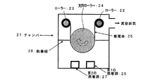
実験1と同様の集電体を用い、図2に示す蒸着装置により、この集電体の上に非晶質薄膜を形成した。薄膜形成条件を表5に示す。
(Experiment 2)
(Production of negative electrode)
Using the same current collector as in Experiment 1, an amorphous thin film was formed on the current collector using the vapor deposition apparatus shown in FIG. Table 5 shows the thin film formation conditions.
具体的な薄膜の堆積は以下のようにして行った。すなわち、チャンバー内を5×10⁻⁵Paまで真空排気した後、第1の蒸着源及び第2の蒸着源の蒸着材料を入れておいたるつぼに所定の電力の電子ビームを照射することによりそれぞれの材料を蒸発させ、集電体を矢印の方向に送りながら非晶質薄膜を堆積させた。第1の蒸着源及び第2の蒸着源を単独で使用した場合に堆積される薄膜を蛍光X分析法によって評価し、2つ同時に使用した場合のCoの濃度分布を求めた。非晶質薄膜中のコバルト濃度を変化させると、単位体積当たりのリチウムを吸蔵放出する量が変化する。このため、予めリチウム金属対極を使用した電池を試作し、対リチウム金属電位が0〜2Vの範囲で充放電を行った場合に、単位面積当たりのリチウム吸蔵放出量が同じになるように薄膜の厚みを調整している。 A specific thin film was deposited as follows. That is, after evacuating the chamber to 5 × 10 −5 Pa, each of the crucibles containing the vapor deposition materials of the first vapor deposition source and the second vapor deposition source is irradiated with an electron beam of a predetermined power. The material was evaporated and an amorphous thin film was deposited while feeding the current collector in the direction of the arrow. The thin film deposited when the first vapor deposition source and the second vapor deposition source were used alone was evaluated by the fluorescent X analysis method, and the Co concentration distribution when two were used simultaneously was determined. When the cobalt concentration in the amorphous thin film is changed, the amount of occlusion / release of lithium per unit volume changes. For this reason, when a battery using a lithium metal counter electrode is prototyped and charged / discharged in the range of 0 to 2 V with respect to the lithium metal potential, the thin film is formed so that the lithium occlusion / release amount per unit area is the same. The thickness is adjusted.
得られた薄膜を集電体とともに2.5cm×2.5cmの大きさに切取り、負極タブを取り付けることにより、負極a2及びb4,b5を得た。 The obtained thin film was cut into a size of 2.5 cm × 2.5 cm together with the current collector, and negative electrode a2 and b4, b5 were obtained by attaching a negative electrode tab.
負極a2及びb4,b5における薄膜中のコバルト濃度を表6に示す。 Table 6 shows the cobalt concentration in the thin film in the negative electrodes a2 and b4, b5.
〔正極及び非水電解質の作製〕
実験1と同様にして正極及び非水電解質を作製した。
[Production of positive electrode and non-aqueous electrolyte]
A positive electrode and a nonaqueous electrolyte were produced in the same manner as in Experiment 1.
〔電池の作製〕
上記負極a2及びb4,b5を用いて、実験1と同様にして電池A2及び電池B4,B5を作製した。
[Production of battery]
Using the negative electrodes a2 and b4 and b5, a battery A2 and batteries B4 and B5 were produced in the same manner as in Experiment 1.
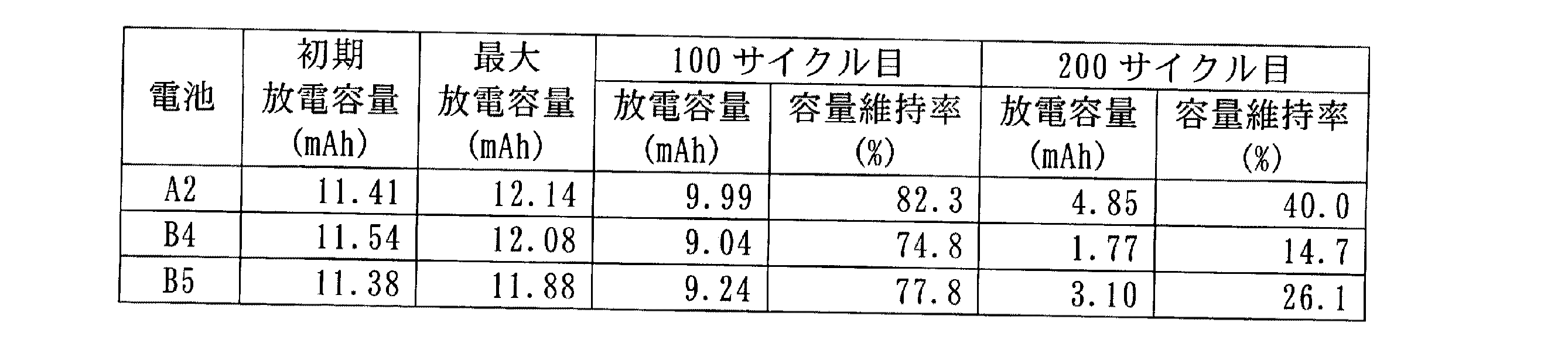
〔充放電サイクル試験〕
上記のように作製したリチウム二次電池A2及びB4,B5について、実験1と同様の条件で充放電サイクル試験を行った。結果を表7に示す。
[Charge / discharge cycle test]
The lithium secondary batteries A2 and B4 and B5 produced as described above were subjected to a charge / discharge cycle test under the same conditions as in Experiment 1. The results are shown in Table 7.
1…チャンバー
2,3…ローラー
4…支持ローラー
5…集電体
6…第1のスパッタ源
7…高周波電源
8…直流パルス電源
9…第2のスパッタ源
10…防着板
21…チャンバー
22,23…ローラー
24…支持ローラー
25…集電体
26…第1の蒸着源
27…第2の蒸着源
28…防着板
DESCRIPTION OF SYMBOLS 1 ...
Claims (8)
前記薄膜が前記集電体表面の主成分とは異なる金属を含み、かつ該金属の濃度が前記薄膜の集電体側から表面側に向かって減少していることを特徴とするリチウム二次電池。 In a lithium secondary battery comprising a negative electrode using a thin film containing silicon deposited on a current collector surface as an active material, a positive electrode, and a non-aqueous electrolyte,
The lithium secondary battery, wherein the thin film contains a metal different from a main component of the current collector surface, and the concentration of the metal decreases from the current collector side to the surface side of the thin film.
気相中に原料を放出して供給する方法であって、前記金属の放出源を前記シリコンを含む原料の放出源より手前に配置し、これらの放出源の上を前記集電体が通ることにより、前記集電体上に前記薄膜が形成されることを特徴とするリチウム二次電池用負極の製造方法。 A negative electrode using, as an active material, a thin film containing silicon deposited on the surface of a current collector, wherein the thin film contains a metal different from a main component of the current collector surface, and the concentration of the metal is In the method for producing a negative electrode for a lithium secondary battery that decreases from the current collector side toward the surface side,
A method of discharging and supplying a raw material into a gas phase, wherein the metal emission source is disposed in front of the silicon-containing raw material emission source, and the current collector passes over these emission sources. The method for producing a negative electrode for a lithium secondary battery, wherein the thin film is formed on the current collector.
Priority Applications (1)
| Application Number | Priority Date | Filing Date | Title |
|---|---|---|---|
| JP2004102371A JP2005293852A (en) | 2004-03-31 | 2004-03-31 | Manufacturing method of lithium secondary battery and anode for the lithium secondary battery |
Applications Claiming Priority (1)
| Application Number | Priority Date | Filing Date | Title |
|---|---|---|---|
| JP2004102371A JP2005293852A (en) | 2004-03-31 | 2004-03-31 | Manufacturing method of lithium secondary battery and anode for the lithium secondary battery |
Publications (1)
| Publication Number | Publication Date |
|---|---|
| JP2005293852A true JP2005293852A (en) | 2005-10-20 |
Family
ID=35326577
Family Applications (1)
| Application Number | Title | Priority Date | Filing Date |
|---|---|---|---|
| JP2004102371A Pending JP2005293852A (en) | 2004-03-31 | 2004-03-31 | Manufacturing method of lithium secondary battery and anode for the lithium secondary battery |
Country Status (1)
| Country | Link |
|---|---|
| JP (1) | JP2005293852A (en) |
Cited By (2)
| Publication number | Priority date | Publication date | Assignee | Title |
|---|---|---|---|---|
| JP2006260944A (en) * | 2005-03-17 | 2006-09-28 | Matsushita Electric Ind Co Ltd | Negative electrode for lithium ion secondary battery, method for producing the same, and lithium ion secondary battery using the same |
| CN112514116A (en) * | 2018-08-23 | 2021-03-16 | 株式会社Lg化学 | Silicon-based composite material, negative electrode comprising same, and lithium secondary battery |
Citations (8)
| Publication number | Priority date | Publication date | Assignee | Title |
|---|---|---|---|---|
| JPH0536401A (en) * | 1991-07-30 | 1993-02-12 | Japan Storage Battery Co Ltd | Lithium secondary battery |
| JP2000100429A (en) * | 1998-09-18 | 2000-04-07 | Canon Inc | Electrode structure and secondary battery |
| JP2001273892A (en) * | 2000-03-28 | 2001-10-05 | Sanyo Electric Co Ltd | Secondary cell |
| JP2002319408A (en) * | 2001-04-23 | 2002-10-31 | Sanyo Electric Co Ltd | Lithium secondary battery electrode and lithium secondary battery |
| JP2003007305A (en) * | 2001-04-19 | 2003-01-10 | Sanyo Electric Co Ltd | Electrode for secondary lithium battery and secondary lithium battery |
| JP2003017039A (en) * | 2001-06-28 | 2003-01-17 | Sanyo Electric Co Ltd | Device and method of forming electrode for lithium secondary battery |
| JP2005183365A (en) * | 2003-11-27 | 2005-07-07 | Matsushita Electric Ind Co Ltd | Energy device and manufacturing method thereof |
| JP2005197080A (en) * | 2004-01-07 | 2005-07-21 | Nec Corp | Anode for secondary battery and secondary battery using it |
-
2004
- 2004-03-31 JP JP2004102371A patent/JP2005293852A/en active Pending
Patent Citations (8)
| Publication number | Priority date | Publication date | Assignee | Title |
|---|---|---|---|---|
| JPH0536401A (en) * | 1991-07-30 | 1993-02-12 | Japan Storage Battery Co Ltd | Lithium secondary battery |
| JP2000100429A (en) * | 1998-09-18 | 2000-04-07 | Canon Inc | Electrode structure and secondary battery |
| JP2001273892A (en) * | 2000-03-28 | 2001-10-05 | Sanyo Electric Co Ltd | Secondary cell |
| JP2003007305A (en) * | 2001-04-19 | 2003-01-10 | Sanyo Electric Co Ltd | Electrode for secondary lithium battery and secondary lithium battery |
| JP2002319408A (en) * | 2001-04-23 | 2002-10-31 | Sanyo Electric Co Ltd | Lithium secondary battery electrode and lithium secondary battery |
| JP2003017039A (en) * | 2001-06-28 | 2003-01-17 | Sanyo Electric Co Ltd | Device and method of forming electrode for lithium secondary battery |
| JP2005183365A (en) * | 2003-11-27 | 2005-07-07 | Matsushita Electric Ind Co Ltd | Energy device and manufacturing method thereof |
| JP2005197080A (en) * | 2004-01-07 | 2005-07-21 | Nec Corp | Anode for secondary battery and secondary battery using it |
Cited By (2)
| Publication number | Priority date | Publication date | Assignee | Title |
|---|---|---|---|---|
| JP2006260944A (en) * | 2005-03-17 | 2006-09-28 | Matsushita Electric Ind Co Ltd | Negative electrode for lithium ion secondary battery, method for producing the same, and lithium ion secondary battery using the same |
| CN112514116A (en) * | 2018-08-23 | 2021-03-16 | 株式会社Lg化学 | Silicon-based composite material, negative electrode comprising same, and lithium secondary battery |
Similar Documents
| Publication | Publication Date | Title |
|---|---|---|
| JP3733071B2 (en) | Lithium battery electrode and lithium secondary battery | |
| JP4610213B2 (en) | Lithium secondary battery and manufacturing method thereof | |
| JP4027255B2 (en) | Negative electrode for lithium secondary battery and method for producing the same | |
| JP4027966B2 (en) | LITHIUM SECONDARY BATTERY ANODE, PROCESS FOR PRODUCING THE SAME, AND LITHIUM SECONDARY BATTERY HAVING A LITHIUM SECONDARY BATTERY ANODE | |
| JP3913490B2 (en) | Method for producing electrode for lithium secondary battery | |
| JP4497899B2 (en) | Lithium secondary battery | |
| CN1983681A (en) | Negative electrode for lithium secondary battery and lithium secondary battery using the negative electrode | |
| JP4895503B2 (en) | Lithium secondary battery | |
| JP2004288520A (en) | Negative electrode for lithium secondary battery and lithium secondary battery | |
| WO2010110205A1 (en) | Lithium ion secondary battery, electrode for the battery, and electrodeposited copper foil for the electrode for the battery | |
| JP2007234336A (en) | Lithium secondary battery | |
| WO2010016217A1 (en) | Lithium secondary battery manufacturing method and lithium secondary battery | |
| JP2005150038A (en) | Lithium secondary battery | |
| JP3670938B2 (en) | Lithium secondary battery | |
| JP4368193B2 (en) | Lithium precursor battery and method for producing lithium secondary battery | |
| JP4953583B2 (en) | Lithium secondary battery | |
| US20080026289A1 (en) | Non-aqueous electrolyte secondary battery | |
| JP2002289177A (en) | Lithium secondary battery and electrode for it | |
| JP5127888B2 (en) | Lithium secondary battery and manufacturing method thereof | |
| JP4471603B2 (en) | Lithium secondary battery | |
| JP4436624B2 (en) | Lithium secondary battery | |
| JP4212439B2 (en) | How to use lithium secondary battery | |
| JP4259809B2 (en) | Method for producing negative electrode for lithium secondary battery | |
| JP2005293852A (en) | Manufacturing method of lithium secondary battery and anode for the lithium secondary battery | |
| JP2005149786A (en) | Lithium secondary battery and its manufacturing method |
Legal Events
| Date | Code | Title | Description |
|---|---|---|---|
| A621 | Written request for application examination |
Free format text: JAPANESE INTERMEDIATE CODE: A621 Effective date: 20061218 |
|
| A977 | Report on retrieval |
Free format text: JAPANESE INTERMEDIATE CODE: A971007 Effective date: 20100115 |
|
| A131 | Notification of reasons for refusal |
Free format text: JAPANESE INTERMEDIATE CODE: A131 Effective date: 20100126 |
|
| A521 | Written amendment |
Free format text: JAPANESE INTERMEDIATE CODE: A523 Effective date: 20100304 |
|
| A02 | Decision of refusal |
Free format text: JAPANESE INTERMEDIATE CODE: A02 Effective date: 20110301 |