JP2005293665A - Transportation apparatus - Google Patents

Transportation apparatus Download PDF

Info

Publication number
JP2005293665A
JP2005293665A JP2004103997A JP2004103997A JP2005293665A JP 2005293665 A JP2005293665 A JP 2005293665A JP 2004103997 A JP2004103997 A JP 2004103997A JP 2004103997 A JP2004103997 A JP 2004103997A JP 2005293665 A JP2005293665 A JP 2005293665A
Authority
JP
Japan
Prior art keywords
conveyed
guide
transport
optical disk
disk
Prior art date
Legal status (The legal status is an assumption and is not a legal conclusion. Google has not performed a legal analysis and makes no representation as to the accuracy of the status listed.)
Pending
Application number
JP2004103997A
Other languages
Japanese (ja)
Inventor
Takashi Kosho
崇 古庄
Kenji Uchiyama
賢治 内山
Eiichi Takahashi
栄一 高橋
Takaaki Musha
敬昭 武者
Current Assignee (The listed assignees may be inaccurate. Google has not performed a legal analysis and makes no representation or warranty as to the accuracy of the list.)
Tohoku Pioneer Corp
Pioneer Corp
Original Assignee
Tohoku Pioneer Corp
Pioneer Electronic Corp
Priority date (The priority date is an assumption and is not a legal conclusion. Google has not performed a legal analysis and makes no representation as to the accuracy of the date listed.)
Filing date
Publication date
Application filed by Tohoku Pioneer Corp, Pioneer Electronic Corp filed Critical Tohoku Pioneer Corp
Priority to JP2004103997A priority Critical patent/JP2005293665A/en
Publication of JP2005293665A publication Critical patent/JP2005293665A/en
Pending legal-status Critical Current

Links

Images

Landscapes

  • Feeding And Guiding Record Carriers (AREA)

Abstract

<P>PROBLEM TO BE SOLVED: To provide a disk apparatus which can transport an optical disk well. <P>SOLUTION: This apparatus is provided with a holder 523 which is projected toward a transportation path along a direction crossing to a transportation direction for the transportation path of an optical disk 10 and of which the height size is heightened gradually, and a transportation roller 530 arranged rotatably having a rotary axis direction to a direction crossing to the transportation direction at a position at which it almost opposes to the holder 523 through the transportation path and having a second guide plane 533 formed in a size of a diameter and in a state in which a bus line is tilted to both end parts at a large slant angle. In the optical disk 10 held between the holder 523 and the second guide plane 533 of the transportation roller 530, since holding force from the second guide plane 533 is operated to both side outside of the transportation direction more than holding force from the holder 523, the optical disk 10 is not warped to a label plane side, scratch for the label plane is prevented and the optical disk 10 can be transported well. <P>COPYRIGHT: (C)2006,JPO&NCIPI

Description

本発明は、被搬送物を搬送する搬送装置に関する。   The present invention relates to a transport apparatus that transports an object to be transported.

従来、ディスク装置などに用いられる搬送装置として、ディスク状の記録媒体が開口部から挿入されると所定の処理位置まで搬送する、いわゆるスロットインタイプの搬送装置が知られている。このスロットインタイプの搬送装置が用いられたディスク装置として、挿入されるディスク状の記録媒体の厚さ方向で略対向する位置に設けられたガイド部材と回転するローラとを備えた構成が知られている(例えば、特許文献1または特許文献2参照)。   2. Description of the Related Art Conventionally, a so-called slot-in type conveying device is known as a conveying device used for a disk device or the like, which conveys a predetermined recording position when a disk-shaped recording medium is inserted from an opening. As a disk apparatus using this slot-in type conveying apparatus, a structure including a guide member and a rotating roller provided at positions substantially opposed to each other in the thickness direction of a disk-shaped recording medium to be inserted is known. (For example, refer to Patent Document 1 or Patent Document 2).

特許文献1に記載のものは、ローラが、搬送するディスク状の記録媒体の記録面側に設けられ、その搬送方向に直交して長尺に、かつ両端部から中央部に向かって径が小さくなる鼓形に形成されている。また、ガイド部材は、ディスク状記録媒体のレーベル面側に設けられ、中央部から両端部に向けて徐々に傾斜したテーパ面を有して形成されている。このように、ローラとガイド部材のテーパ面との間隔距離が中央部よりも両端部において小さくなっているので、ディスク状記録媒体は、その外周縁部がローラおよびガイド部材で挟持され、搬送時にディスク状記録媒体の記録面にローラが接触しないようになっている。そして、ガイド部材における傾斜面の両側端部には、開口部の上部と略平行になるように切除された平面が形成されており、この平面で案内することで、小径のディスク状記録媒体であっても搬送時に傾くことを防止する構成が採られている。   In the apparatus described in Patent Document 1, a roller is provided on the recording surface side of a disk-shaped recording medium to be conveyed, and is elongated in a direction orthogonal to the conveying direction and the diameter decreases from both ends toward the center. It is formed into a drum shape. The guide member is provided on the label surface side of the disc-shaped recording medium, and has a tapered surface that is gradually inclined from the center toward both ends. As described above, since the distance between the roller and the taper surface of the guide member is smaller at both ends than the center, the outer peripheral edge of the disc-shaped recording medium is sandwiched between the roller and the guide member, The roller does not come into contact with the recording surface of the disk-shaped recording medium. A flat surface cut out so as to be substantially parallel to the upper portion of the opening is formed at both end portions of the inclined surface of the guide member. By guiding in this plane, a small-diameter disk-shaped recording medium can be used. Even if it exists, the structure which prevents tilting at the time of conveyance is taken.

特許文献2に記載のものは、特許文献1と略同様に鼓形に形成されたローラと、このローラに対向して設けられたガイド部材とを備えている。そして、ガイド部材は、ローラに対して搬送方向の前後一対からなる傾斜面を有し、これら一対の傾斜面とローラとでディスク状記録媒体を挟持することで、搬送時にディスク状記録媒体の記録面にローラが接触しないようになっているとともに、ディスク状記録媒体を上下に傾かせずに安定して搬送する構成が採られている。   The thing of patent document 2 is equipped with the roller formed in the drum shape substantially like patent document 1, and the guide member provided facing this roller. The guide member has a pair of inclined surfaces in the conveyance direction with respect to the rollers, and the pair of inclined surfaces and the rollers sandwich the disk-shaped recording medium so that the recording of the disk-shaped recording medium is performed at the time of conveyance. A configuration is adopted in which the roller does not come into contact with the surface and the disc-shaped recording medium is stably conveyed without being tilted up and down.

特開2002−329359号公報(第3頁、図1)JP 2002-329359 A (page 3, FIG. 1) 特開2003−77198号公報(第3頁、図5、6)JP 2003-77198 A (page 3, FIGS. 5 and 6)

しかしながら、上記特許文献1および特許文献2に記載のような従来の構成では、ディスク状記録媒体の記録面にローラが接触しないようになっているものの、レーベル面にガイド部材が接触して傷がついてしまい、良好に搬送できないおそれがある。すなわち、上述のようなローラでは、その回転によりディスク状記録媒体を搬送することから、当接面を所定の弾性を有した軟質部材にて形成し、所定の押圧力でディスク状記録媒体に押圧する状態に構成することが考えられる。このことにより、ローラを軟質部材から形成してディスク状記録媒体に押圧すると、ローラの当接部分が変形することにより、ディスク状記録媒体の外周縁部よりも中央側にずれた位置にローラからの挟持力が作用し、ディスク状記録媒体がガイド部材側に凸に反ってしまう。このため、ディスク状記録媒体のレーベル面がガイド部材に接触して傷がついてしまうおそれがある問題が一例として挙げられる。   However, in the conventional configuration described in Patent Document 1 and Patent Document 2, the roller does not contact the recording surface of the disk-shaped recording medium, but the guide member contacts the label surface and scratches are generated. There is a possibility that it cannot be transported well. That is, since the roller as described above conveys the disk-shaped recording medium by its rotation, the contact surface is formed of a soft member having a predetermined elasticity and pressed against the disk-shaped recording medium with a predetermined pressing force. It is conceivable to configure in such a state. As a result, when the roller is formed from a soft member and pressed against the disc-shaped recording medium, the contact portion of the roller is deformed, so that the roller is displaced to the center side from the outer peripheral edge of the disc-shaped recording medium. Thus, the disc-shaped recording medium is warped convexly toward the guide member. For this reason, there is a problem that the label surface of the disk-shaped recording medium may be damaged by coming into contact with the guide member.

本発明は、上述したような実情などに鑑みて、ディスク状の被搬送物を良好に搬送する搬送装置を提供することを目的とする。   The present invention has been made in view of the above-described circumstances, and an object of the present invention is to provide a transport device that satisfactorily transports a disk-shaped object.

請求項1に記載の発明は、被搬送物をケース内外へ搬送する回転可能な回転部材と、前記回転部材の回転により搬送される前記被搬送物を案内するガイド部材と、を備え、前記ガイド部材は、前記被搬送物の搬送経路における搬送方向に対して交差する方向に長手状で、かつその中央から長手方向の両端側に向かうにしたがって前記搬送経路側に傾斜した傾斜部を有し、前記回転部材は、前記搬送経路に対して交差する方向に延在する回転軸と、その回転軸の周面に取り付けられた弾性変形可能な軟質部材とを有し、前記軟質部材は、その中間部の外周位置と両端縁とを結ぶ直線における軸方向に対する傾斜角度より大きな傾斜角度で母線が傾斜する状態に、少なくとも軸方向の両端部における径寸法が前記中間部付近における径寸法より径大に形成され、前記径大に形成された部分と前記傾斜部とが前記被搬送物を狭持して、前記被搬送物を前記ケース内外に搬送することを特徴とする搬送装置である。   The invention according to claim 1 includes a rotatable rotating member that conveys the object to be conveyed in and out of the case, and a guide member that guides the object to be conveyed that is conveyed by the rotation of the rotating member. The member has an inclined portion that is long in the direction intersecting the transport direction in the transport path of the transported object and that is inclined toward the transport path side from the center toward both ends in the longitudinal direction. The rotating member includes a rotating shaft extending in a direction intersecting the transport path, and an elastically deformable soft member attached to a peripheral surface of the rotating shaft. In a state where the bus bar is inclined at an inclination angle larger than the inclination angle with respect to the axial direction in the straight line connecting the outer peripheral position of the portion and both end edges, at least the radial dimension at both axial end portions is larger than the radial dimension near the intermediate portion. It is formed, in the portion formed the large diameter and the inclined portion is sandwiched the transported object, wherein a conveying device, characterized in that for conveying the conveying object on the casing and out.

請求項2に記載の発明は、被搬送物をケース内外へ搬送する回転可能な回転部材と、前記回転部材の回転により搬送される前記被搬送物を案内するガイド部材と、を備え、前記ガイド部材は、前記被搬送物の搬送経路における搬送方向に対して交差する方向に長手状で、かつその中央から長手方向の両端側に向かうにしたがって前記搬送経路側に傾斜した傾斜部を有し、前記回転部材は、前記搬送方向に対して交差する方向に延在する回転軸と、その回転軸の周面に取り付けられるとともに前記被搬送物を前記ガイド部材と狭持する弾性変形可能な軟質部材を有し、前記軟質部材は前記被搬送物に挟持力を作用させる位置が、前記ガイド部が前記被搬送物に挟持力を作用させる位置よりも、前記搬送方向の両側方外側に位置する状態に形成されていることを特徴とする搬送装置である。   The invention according to claim 2 includes a rotatable rotating member that conveys the object to be conveyed in and out of the case, and a guide member that guides the object to be conveyed that is conveyed by the rotation of the rotating member. The member has an inclined portion that is long in the direction intersecting the transport direction in the transport path of the transported object and that is inclined toward the transport path side from the center toward both ends in the longitudinal direction. The rotating member includes a rotating shaft extending in a direction intersecting the conveying direction, and an elastically deformable soft member that is attached to a peripheral surface of the rotating shaft and holds the object to be conveyed with the guide member The soft member has a position where the holding force is applied to the object to be transported, and the position where the guide portion is located on both outer sides in the transport direction than the position where the guide part applies the holding force to the object to be transported. Formed into It is the conveyance device according to claim is.

請求項7に記載の発明は、被搬送物をケース内外へ搬送する回転可能な回転部材と、前記回転部材の回転により搬送される前記被搬送物を案内するガイド部材と、を備え、前記ガイド部材は、前記被搬送物の搬送経路における搬送方向に対して交差する方向に長手状で、かつその中央から長手方向の両端側に向かうにしたがって前記搬送経路側に傾斜した傾斜部を有し、前記回転部材は、前記搬送経路に対して交差する方向に延在する回転軸と、その回転軸の周面に移動可能に取り付けられた弾性変形可能な一対の軟質部材とを有し、前記一対の軟質部材は、前記回転軸の中間側から端部側に向けて次第に径大に形成されており、前記径大に形成された部分と前記傾斜部とが前記被搬送物を狭持するとともに、前記被搬送物が前記ケース内外に搬送するにしたがって前記一対の軟質部材が互いに近づいたり離れたりすることを特徴とする搬送装置である。   The invention according to claim 7 includes a rotatable rotating member that conveys the object to be conveyed in and out of the case, and a guide member that guides the object to be conveyed that is conveyed by the rotation of the rotating member. The member has an inclined portion that is long in the direction intersecting the transport direction in the transport path of the transported object and that is inclined toward the transport path side from the center toward both ends in the longitudinal direction. The rotating member has a rotating shaft extending in a direction intersecting the transport path, and a pair of elastically deformable soft members movably attached to a peripheral surface of the rotating shaft, The soft member is formed so as to gradually increase in diameter from the intermediate side to the end side of the rotating shaft, and the portion formed in the large diameter and the inclined portion sandwich the object to be conveyed. The transported object is inside or outside the case A conveying device, characterized in that said pair of flexible members according to transport and away from each other.

〔第1の実施の形態〕
以下、本発明の第1の実施の形態を図面に基づいて説明する。本実施の形態では、被搬送物としてのディスク状記録媒体である光ディスクに情報を記録および読み出すいわゆるスロットインタイプのディスク装置に適用して説明するが、ディスク状の被搬送物を搬送するいずれの搬送装置を対象とすることができる。さらには、光ディスクの情報処理をするディスク装置に限らず、いずれのディスク装置にも適用できる。また、ディスク状の被搬送物としては、光ディスクに限らず、磁気ディスク、光磁気ディスクなどのいずれのディスク状記録媒体を対象とすることができる。また、例えば携帯型のパーソナルコンピュータなどの電気機器に装着されるいわゆる薄型のスロットインタイプで例示するが、例えばゲーム機や映像データの録画などの記録や再生のための処理をする再生装置などの単体の構成としてもよく、薄型の構成に限られない。
[First Embodiment]
DESCRIPTION OF EXEMPLARY EMBODIMENTS Hereinafter, a first embodiment of the invention will be described with reference to the drawings. In the present embodiment, description will be made by applying the present invention to a so-called slot-in type disk device which records and reads information on an optical disk which is a disk-shaped recording medium as a conveyed object. The conveyance device can be targeted. Furthermore, the present invention is not limited to a disk device that performs information processing of an optical disk, and can be applied to any disk device. Further, the disk-shaped object to be conveyed is not limited to an optical disk, but can be any disk-shaped recording medium such as a magnetic disk or a magneto-optical disk. Also, for example, a so-called thin slot-in type that is mounted on an electric device such as a portable personal computer is exemplified. However, for example, a game machine or a playback device that performs processing for recording and playback such as video data recording It may be a single structure, and is not limited to a thin structure.

(ディスク装置の構成)
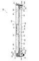
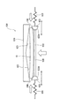
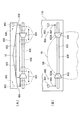
図1は、第1の実施の形態に係るディスク装置の概略構成を示す一部を切り欠いた平面図である。図2は、ディスク装置の概略構成を示す一部を切り欠いた平面図であり、光ディスクの略半分が挿入された状態を説明する図である。図3は、ディスク搬送部を示す一部を切り欠いた平面図である。図4は、ディスク搬送部を示す一部を切り欠いた正面図である。図5は、ディスク搬送部による光ディスクの搬送状態を示す正面から見た説明図である。図6は、ディスク搬送部による光ディスクの搬送状態を示す側面から見た説明図である。図7は、搬送状態における光ディスクに作用する挟持力を示す説明図である。図8は、搬送状態における光ディスクの変形状態を示す説明図である。
(Disk unit configuration)
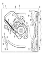
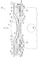
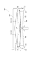
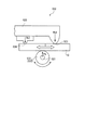
FIG. 1 is a plan view with a part cut away showing a schematic configuration of the disk device according to the first embodiment. FIG. 2 is a plan view showing a schematic configuration of the disk device with a part cut away, and is a diagram for explaining a state in which approximately half of the optical disk is inserted. FIG. 3 is a plan view with a part cut away showing the disk transport section. FIG. 4 is a front view with a part cut away showing the disk transport unit. FIG. 5 is an explanatory diagram viewed from the front showing the state of the optical disk transported by the disk transport unit. FIG. 6 is an explanatory view seen from the side showing the state of the optical disk transported by the disk transport section. FIG. 7 is an explanatory diagram showing the clamping force acting on the optical disc in the transported state. FIG. 8 is an explanatory diagram showing a deformed state of the optical disc in the transported state.

図1において、100はディスク装置で、このディスク装置100は、例えば車載用のナビゲーション装置に装着されるいわゆる薄型のスロットインタイプである。このディスク装置100は、着脱可能に装着されるディスク状の被搬送物であるディスク状記録媒体としての円板状の光ディスク10における少なくとも一面に設けられた図示しない記録面に記録された情報を読み出す情報処理である読取処理および記録面へ各種情報を記録する情報処理である記録処理をする。そして、ディスク装置100は、例えば金属製で内部空間を有する略箱形状のケース体110を有している。このケース体110には、一側面に例えば合成樹脂にて細長板状に形成された化粧板111が設けられている。この化粧板111には、長手方向に沿って細長スリット状に設けられた図示しない開口部が設けられている。また、ケース体110内には、情報処理を実行するディスク処理部200と、搬送装置としてのディスク搬送部500と、ディスク装置100全体の動作を制御する図示しないシステム制御部と、が配設されている。   In FIG. 1, reference numeral 100 denotes a disk device, and this disk device 100 is a so-called thin slot-in type that is mounted on, for example, an in-vehicle navigation device. The disk device 100 reads information recorded on a recording surface (not shown) provided on at least one surface of a disk-shaped optical disk 10 as a disk-shaped recording medium that is a disk-shaped transported object that is detachably mounted. A reading process, which is information processing, and a recording process, which is information processing for recording various information on the recording surface, are performed. The disk device 100 includes a substantially box-shaped case body 110 made of, for example, metal and having an internal space. The case body 110 is provided with a decorative plate 111 formed in an elongated plate shape with, for example, a synthetic resin on one side surface. The decorative plate 111 is provided with an opening (not shown) provided in the form of an elongated slit along the longitudinal direction. Also, in the case body 110, a disk processing unit 200 that performs information processing, a disk transport unit 500 as a transport device, and a system control unit (not shown) that controls the operation of the entire disk device 100 are disposed. ing.

ディスク処理部200は、対向する一対の台座部210を有している。これら台座部210は、互いに対向方向で回動可能にケース体110内に配設されている。そして、一方の台座部には、他方の台座部に回転可能に支持された図示しない回転子とともに光ディスク10を回転駆動するディスク回転駆動手段220が配設されている。このディスク回転駆動手段220は、一方の台座部210に配設されたスピンドルモータ221と、このスピンドルモータ221の出力軸に一体的に設けられたターンテーブル222と、を備えている。スピンドルモータ221は、システム制御部に制御可能に接続され、システム制御部から供給される電力により駆動する。ターンテーブル222は、光ディスク10の中心に開口形成された軸孔10Aに嵌挿して軸支する軸支部である略円柱状の回転軸222Aと、この回転軸222Aの外周面にフランジ状に突設され光ディスク10の軸孔10Aの周縁が載置されて支持する鍔部222Bと、を備えている。そして、ターンテーブル222は、互いに対向する方向に台座部210が回動されることで、他方の台座部に支持された図示しない回転子とにより光ディスク10を挾持する。この挾持された光ディスク10は、スピンドルモータ221の駆動により回転するターンテーブル222および挾持する回転子とともに回転される。   The disk processing unit 200 has a pair of pedestal portions 210 facing each other. These pedestals 210 are disposed in the case body 110 so as to be rotatable in directions opposite to each other. One pedestal portion is provided with a disk rotation driving means 220 for rotating the optical disk 10 together with a rotor (not shown) rotatably supported on the other pedestal portion. The disk rotation driving means 220 includes a spindle motor 221 disposed on one pedestal 210 and a turntable 222 provided integrally with the output shaft of the spindle motor 221. The spindle motor 221 is connected to the system control unit in a controllable manner, and is driven by electric power supplied from the system control unit. The turntable 222 has a substantially cylindrical rotary shaft 222A that is a shaft support portion that is inserted into and supported by a shaft hole 10A formed in the center of the optical disc 10, and a flange-like projection on the outer peripheral surface of the rotary shaft 222A. And a flange 222B on which the periphery of the shaft hole 10A of the optical disk 10 is placed and supported. Then, the turntable 222 holds the optical disc 10 by a rotor (not shown) supported by the other pedestal portion by rotating the pedestal portion 210 in a direction facing each other. The held optical disk 10 is rotated together with a turntable 222 that rotates by driving of the spindle motor 221 and a rotor that is held.

また、一方の台座部210には、情報処理部240が配設されている。この情報処理部240は、一対のガイドシャフト230間に架橋する状態に支持される移動保持部241を備えている。この移動保持部241には、ガイドシャフト230を移動可能に嵌挿する保持部241Aと、移動規制爪部241Bと、を備えている。また、移動保持部241には、図示しない光源と、この光源からの光を収束するレンズ242Aと、光ディスク10で反射された出射光を検出する図示しない光センサとを備えたピックアップ242が配設されている。このピックアップ242は、システム制御部に信号を送受信可能に接続され、システム制御部の制御により、光ディスク10の記録面に記録された各種情報を読み取って出力回路部へ出力する読取処理や、システム制御部からの各種情報を記録面に記録する記録処理を実施する。   Further, an information processing unit 240 is disposed on one pedestal unit 210. The information processing unit 240 includes a movement holding unit 241 that is supported so as to bridge between the pair of guide shafts 230. The movement holding portion 241 includes a holding portion 241A into which the guide shaft 230 is movably fitted and a movement restricting claw portion 241B. In addition, the movement holding unit 241 is provided with a pickup 242 including a light source (not shown), a lens 242A for converging light from the light source, and an optical sensor (not shown) for detecting emitted light reflected by the optical disc 10. Has been. The pickup 242 is connected to the system control unit so as to be able to transmit and receive signals. Under the control of the system control unit, the pickup 242 reads various information recorded on the recording surface of the optical disc 10 and outputs the information to the output circuit unit. A recording process for recording various information from the recording unit on the recording surface is performed.

さらに、一方の台座部210には、情報処理部240を移動させる処理移動手段300が配設されている。この処理移動手段300は、ガイドシャフト230に支持された情報処理部240を移動させる。この処理移動手段300は、電動モータであるステッピングモータなどの移動用電動モータ310と、スクリュ部材としてのリードスクリュ320と、を備えている。移動用電動モータ310は、システム制御部に制御可能に接続され、システム制御部から供給される電力により駆動する。リードスクリュ320は、例えば金属製の細長棒状に形成され、情報処理部240の移動規制爪部241Bが係合される係合部としての螺旋状の係合溝が外周面に設けられている。   Furthermore, one pedestal unit 210 is provided with processing moving means 300 for moving the information processing unit 240. The processing moving unit 300 moves the information processing unit 240 supported by the guide shaft 230. The processing moving means 300 includes a moving electric motor 310 such as a stepping motor that is an electric motor, and a lead screw 320 as a screw member. The electric motor 310 for movement is connected to the system control unit in a controllable manner, and is driven by electric power supplied from the system control unit. The lead screw 320 is formed in, for example, a metal elongated bar shape, and a helical engagement groove is provided on the outer peripheral surface as an engagement portion with which the movement restricting claw portion 241B of the information processing unit 240 is engaged.

また、一方の台座部210には、光ディスク10がターンテーブル222および他方の台座部の回転子で挾持される位置まで搬入されたことを検知する搬入検知手段400が配設されている。この搬入検知手段400は、台座部210に軸支された軸部410と、この軸部410に固定されたアーム部420と、を備えている。アーム部420の一端には、ディスク搬送部500で搬入された光ディスク10に当接する一方の当接部421が設けられており、アーム部420の他端には、図示しない検知スイッチに当接する他方の当接部422が設けられている。また、軸部410には、図示しないねじりコイルばねが設けられており、このねじりコイルばねの付勢力により一方の当接部421が光ディスク10の搬送経路内に突出して設けられている。この一方の当接部421に搬入された光ディスク10が当接することで、アーム部420が軸部410を中心にして回動し、他方の当接部422が検知スイッチに当接し、検知スイッチがオンになる。この検知スイッチのオン信号がシステム制御部へ出力され、このオン信号に基づいて、システム制御部は、一対の台座部210を回動させて、ターンテーブル222および回転子に光ディスク10を挾持させる制御を実施する。   In addition, on one pedestal portion 210, a carry-in detection means 400 for detecting that the optical disk 10 has been carried to a position where it is held by the turntable 222 and the rotor of the other pedestal portion is disposed. The carry-in detection means 400 includes a shaft portion 410 that is pivotally supported by the pedestal portion 210, and an arm portion 420 that is fixed to the shaft portion 410. One end of the arm unit 420 is provided with one abutting part 421 that abuts on the optical disk 10 loaded by the disc transport unit 500, and the other end of the arm part 420 abuts on a detection switch (not shown). The abutting portion 422 is provided. The shaft portion 410 is provided with a torsion coil spring (not shown), and one abutting portion 421 is provided so as to protrude into the transport path of the optical disc 10 by the urging force of the torsion coil spring. When the optical disk 10 carried into one of the contact portions 421 contacts, the arm portion 420 rotates around the shaft portion 410, the other contact portion 422 contacts the detection switch, and the detection switch Turn on. An ON signal of this detection switch is output to the system control unit, and based on this ON signal, the system control unit rotates the pair of pedestal units 210 to hold the optical disc 10 between the turntable 222 and the rotor. To implement.

ディスク搬送部500は、図3および図4に示すように、ケース体110に配設された支持部材510と、この支持部材510に固定されたガイド部材520と、支持部材510に回動自在に支持された回転部材としての搬送ローラ530と、搬送ローラ530を回転駆動する駆動手段540と、光ディスク10の挿入を検知する検知手段550と、を備えている。搬送ローラ530は、光ディスク10の一方の面である記録面側に位置するように設けられ、ガイド部材520は、光ディスク10の他方の面であるレーベル面側に位置するように設けられている。すなわち、ディスク搬送部500は、搬送ローラ530とガイド部材520との間に光ディスク10の搬送経路が設けられ、この搬送経路を通して光ディスク10を搬送方向Tに沿ってケース体110内に搬入またはケース体110内から搬出するものである。   As shown in FIGS. 3 and 4, the disk transport unit 500 includes a support member 510 disposed in the case body 110, a guide member 520 fixed to the support member 510, and a support member 510 that is rotatable. A conveyance roller 530 as a supported rotating member, a driving unit 540 that rotationally drives the conveyance roller 530, and a detection unit 550 that detects insertion of the optical disc 10 are provided. The conveyance roller 530 is provided so as to be positioned on the recording surface side which is one surface of the optical disc 10, and the guide member 520 is provided so as to be positioned on the label surface side which is the other surface of the optical disc 10. That is, the disc transport unit 500 is provided with a transport path for the optical disc 10 between the transport roller 530 and the guide member 520, and the optical disc 10 is carried into the case body 110 along the transport direction T through the transport path or the case body. 110 is carried out from within.

支持部材510は、例えば金属板などにてケース体110の化粧板111に沿って細長状に形成され、その両側端部がケース体110に固定されている。この支持部材510は、ケース体110の上内面に沿って設けられる上面部511と、この上面部511の前部である化粧板111側の端部に折れ曲げ形成された前面部512と、上面部の長手方向両端に折れ曲げ形成された側面部513と、を備えている。そして、支持部材510の上面部511における前方側となる図3の下側の両側端寄りには、長手方向に沿って延びる一対の長孔514が形成されている。また、支持部材510の前面部512における両側端寄りには、長手方向に沿って延びる一対の長孔515が形成されている。   The support member 510 is formed in an elongated shape along the decorative plate 111 of the case body 110 using, for example, a metal plate, and both end portions thereof are fixed to the case body 110. The support member 510 includes an upper surface portion 511 provided along the upper and inner surfaces of the case body 110, a front surface portion 512 formed by being bent at an end portion on the decorative plate 111 side which is a front portion of the upper surface portion 511, and an upper surface. And side portions 513 that are bent at both ends in the longitudinal direction of the portion. A pair of long holes 514 extending along the longitudinal direction is formed near both side ends of the lower side of FIG. 3 that is the front side of the upper surface portion 511 of the support member 510. Further, a pair of long holes 515 extending along the longitudinal direction are formed near both side ends of the front surface portion 512 of the support member 510.

ガイド部材520は、例えば樹脂製で搬送経路における搬送方向Tに対して直交する方向に長手状に形成され、支持部材510の下側となる図4の下側に嵌合固定されている。ガイド部材520は、支持部材510の上面部511に沿った上面部521と、支持部材510の前面部512に沿った前面部522と、を備えている。ガイド部材520の前面部522は、支持部材510の前面部512よりも下方に延びて形成され、つまり搬送経路に向けて突出する高さ寸法が次第に高くなる状態に壁状に形成されている。この前面部522の下端縁には、長手方向中央から両端部に向かって徐々に下がる傾斜を有した一対の傾斜面としてのガイド部であるホルダ523が形成されている。また、ガイド部材520の上面部521におけるケース体110の内方端となる図3の上端には、両端部に向かって徐々に下がる傾斜を有した一対のガイド524が形成されている。ガイド524は、ホルダ523に搬送方向Tで並設され、搬送方向Tに対して略直交する方向に長手状で搬送経路に向けて突出する壁状に設けられている。これらのホルダ523とガイド524とは、互いに略同一高さ位置に設けられ、挿入された光ディスク10の外周縁にレーベル面側から当接するようになっている。また、ガイド部材520の上面部521には、支持部材510の長孔514に近接した位置に当該上面部521を貫通する長孔525が形成されている。   The guide member 520 is made of, for example, resin and is formed in a longitudinal shape in a direction orthogonal to the transport direction T in the transport path, and is fitted and fixed to the lower side of FIG. The guide member 520 includes an upper surface portion 521 along the upper surface portion 511 of the support member 510 and a front surface portion 522 along the front surface portion 512 of the support member 510. The front surface portion 522 of the guide member 520 is formed to extend downward from the front surface portion 512 of the support member 510, that is, is formed in a wall shape so that the height dimension protruding toward the conveyance path gradually increases. At the lower end edge of the front surface portion 522, a holder 523 is formed as a pair of inclined surfaces having a slope that gradually decreases from the center in the longitudinal direction toward both ends. Further, a pair of guides 524 having inclinations gradually decreasing toward both end portions are formed at the upper end of FIG. 3 which is the inner end of the case body 110 in the upper surface portion 521 of the guide member 520. The guide 524 is provided in parallel with the holder 523 in the transport direction T, and is provided in a wall shape that is long in a direction substantially orthogonal to the transport direction T and protrudes toward the transport path. The holder 523 and the guide 524 are provided at substantially the same height, and come into contact with the outer peripheral edge of the inserted optical disk 10 from the label surface side. Further, the upper surface portion 521 of the guide member 520 is formed with a long hole 525 that penetrates the upper surface portion 521 at a position close to the long hole 514 of the support member 510.

搬送ローラ530は、長尺略鼓型に形成され、搬送方向Tに対して交差する方向に回転軸方向を有して回転可能に配設されている。搬送ローラ530は、その長手方向に沿った回転軸531と、長手方向中央から両端部に向かって次第に径大となる一対の第1の傾斜領域としての第1案内面532と、これら一対の第1案内面532の両端に連続して第1案内面532よりも端部に向けて次第に径大に形成された一対の第2の傾斜領域としての第2案内面533と、を備えている。すなわち、第2案内面533で搬送ローラ530の両端部が形成され、その母線は、回転軸531に対する第1案内面532の母線の傾斜角度よりも大きな傾斜角度で傾斜している。これらの第1および第2の案内面532,533は、弾性変形可能な軟質部材から形成され、挿入された光ディスク10の外周縁に記録面側から当接するようになっている。そして、搬送ローラ530の回転軸531両端は、回動部材534に軸支されている。この回動部材534は、例えば金属板などにて搬送ローラ530に沿って細長状に形成され、その両端部534Aが支持部材510の側面部513に軸支され、搬送ローラ530の前方から前方の斜め下方までに渡って回動可能になっている。また、回動部材534の一方の端部と支持部材510との間には、コイルばね534Bが架設されており、このコイルばね534Bによって回動部材534が、搬送ローラ530の前方または前方の斜め下方のいずれかの位置に付勢されるようになっている。   The conveyance roller 530 is formed in a long and substantially drum shape, and is rotatably disposed with a rotation axis direction in a direction intersecting the conveyance direction T. The conveying roller 530 includes a rotation shaft 531 along the longitudinal direction, a pair of first guide surfaces 532 as first inclined regions that gradually increase in diameter from the center in the longitudinal direction toward both ends, and the pair of first rollers. And a second guide surface 533 as a pair of second inclined regions which are continuously formed at both ends of the first guide surface 532 and gradually formed larger in diameter toward the end portion than the first guide surface 532. That is, both end portions of the transport roller 530 are formed by the second guide surface 533, and the bus line is inclined at an inclination angle larger than the inclination angle of the bus line of the first guide surface 532 with respect to the rotation shaft 531. These first and second guide surfaces 532 and 533 are formed of an elastically deformable soft member and come into contact with the outer peripheral edge of the inserted optical disk 10 from the recording surface side. Then, both ends of the rotation shaft 531 of the transport roller 530 are pivotally supported by the rotation member 534. The rotating member 534 is formed in an elongated shape along the conveying roller 530 using, for example, a metal plate, and both end portions 534A thereof are pivotally supported by the side surface portion 513 of the supporting member 510, and the front side of the conveying roller 530 is moved forward. It can be turned to the diagonally lower side. In addition, a coil spring 534B is installed between one end of the rotation member 534 and the support member 510. The coil spring 534B causes the rotation member 534 to move forward or diagonally forward of the conveyance roller 530. It is biased to any position below.

また、搬送ローラ530は、回動部材534の回動に伴って回動し、ガイド部材520との間隔が狭くなって光ディスク10を挟持可能な搬送位置と、ガイド部材520との間隔が広がって光ディスク10を挟持しない退避位置との間を上下に移動するようになっている。すなわち、光ディスク10が挿入されていない状態において、搬送ローラ530は、搬送位置にあってコイルばね534Bにより上方に付勢されているとともに、回動部材534は、搬送ローラ530前方の斜め下方に位置しており、この回動部材534の上側を通して光ディスク10が受け入れ可能になっている。そして、光ディスク10が挿入されてターンテーブル222に軸支される位置まで搬入された状態において、回動部材534は、駆動手段540により搬送ローラ530の前方位置に回動され、開口部の内側を塞ぐとともに、搬送ローラ530は、退避位置に下がって光ディスク10から離れるようになっている。さらに、挿入された光ディスク10を搬出する際には、回動部材534が搬送ローラ530の前方の斜め下方位置に回動され、搬送ローラ530が搬送位置に移動されるようになっている。搬送位置において、搬送ローラ530は、コイルばね534Bによってガイド部材620に向かって付勢されている。   Further, the transport roller 530 rotates with the rotation of the rotation member 534, and the interval between the guide member 520 is narrowed and the distance between the transport position where the optical disk 10 can be sandwiched and the guide member 520 is increased. The optical disk 10 is moved up and down between the retracted positions where the optical disk 10 is not sandwiched. That is, in a state where the optical disk 10 is not inserted, the transport roller 530 is in the transport position and is biased upward by the coil spring 534B, and the rotating member 534 is positioned obliquely below the front of the transport roller 530. The optical disk 10 can be received through the upper side of the rotating member 534. Then, in a state where the optical disk 10 is inserted and carried to a position where it is pivotally supported by the turntable 222, the rotating member 534 is rotated to the front position of the conveying roller 530 by the driving means 540, and inside the opening. At the same time, the conveying roller 530 is lowered to the retracted position so as to be separated from the optical disk 10. Further, when the inserted optical disk 10 is carried out, the rotating member 534 is rotated to an obliquely lower position in front of the conveying roller 530, and the conveying roller 530 is moved to the conveying position. At the transport position, the transport roller 530 is biased toward the guide member 620 by the coil spring 534B.

また、図7に示すように、搬送ローラ530の回転軸531に対する第1案内面532の母線の傾斜角度θ1は、0.42°に設定され、回転軸531に対する第2案内面533の母線の傾斜角度θ2は、8.0°に設定されている。また、回転軸531に対するガイド部材520のホルダ523およびガイド524の傾斜角度θ3は、0.63°に設定されている。すなわち、搬送ローラ530の第1案内面532の傾斜角度θ1よりも、ガイド部材520のホルダ523の傾斜角度θ3が大きく設定され、さらにホルダ523の傾斜角度θ3よりも、搬送ローラ530の第2案内面533の傾斜角度θ2が大きく設定されている。すなわち、θ1<θ3<θ2の関係を満足するように各部の傾斜角度が設定されている。
なお、各部の傾斜角度は、上記に限らず、搬送ローラ530の第1案内面532の傾斜角度θ1は、0.2°以上0.6°以下の範囲、好ましくは、0.3°以上0.5°以下の範囲で設定可能である。また、搬送ローラ530の第2案内面533の傾斜角度θ2は、5.0°以上10°以下の範囲で、好ましくは、7.0°以上9.0°以下の範囲で設定可能である。さらに、ガイド部材520のホルダ523およびガイド524の傾斜角度θ3は、0.4°以上0.8°以下の範囲で、好ましくは、0.5°以上0.7°以下の範囲で設定可能である。
Further, as shown in FIG. 7, the inclination angle θ1 of the first guide surface 532 with respect to the rotation shaft 531 of the transport roller 530 is set to 0.42 °, and the second guide surface 533 with respect to the rotation shaft 531 The inclination angle θ2 is set to 8.0 °. Further, the inclination angle θ3 of the holder 523 of the guide member 520 and the guide 524 with respect to the rotation shaft 531 is set to 0.63 °. That is, the inclination angle θ3 of the holder 523 of the guide member 520 is set larger than the inclination angle θ1 of the first guide surface 532 of the conveyance roller 530, and further, the second guide of the conveyance roller 530 is larger than the inclination angle θ3 of the holder 523. The inclination angle θ2 of the surface 533 is set large. That is, the inclination angle of each part is set so as to satisfy the relationship of θ1 <θ3 <θ2.
The inclination angle of each part is not limited to the above, and the inclination angle θ1 of the first guide surface 532 of the conveying roller 530 is in the range of 0.2 ° to 0.6 °, preferably 0.3 ° to 0. It can be set within a range of 5 ° or less. In addition, the inclination angle θ2 of the second guide surface 533 of the transport roller 530 can be set in the range of 5.0 ° to 10 °, preferably in the range of 7.0 ° to 9.0 °. Furthermore, the inclination angle θ3 of the holder 523 and the guide 524 of the guide member 520 can be set in the range of 0.4 ° to 0.8 °, preferably in the range of 0.5 ° to 0.7 °. is there.

駆動手段540は、搬送モータ541と、この搬送モータ541の駆動力を搬送ローラ530に伝達する伝達機構542と、を備えている。搬送モータ541は、支持部材510の上面部511下側に取り付けられるとともに、システム制御部に制御可能に接続され、システム制御部から供給される電力により駆動する。伝達機構542は、搬送モータ541の出力軸に固定された第1ウォームギア542Aと、この第1ウォームギア542Aに直交して噛号する第2ウォームギア542Bと、この第2ウォームギア542Bに噛号し搬送ローラ530の回転軸531に平行に回転する第3ウォームギア542Cと、この第3ウォームギア542Cに噛号し回転軸531に固定された駆動ギア542Dと、を備えている。そして、搬送モータ541の駆動が伝達機構542を介して搬送ローラ530に伝達され、搬送ローラ530が搬入方向または搬出方向に回転駆動されるようになっている。   The drive unit 540 includes a transport motor 541 and a transmission mechanism 542 that transmits the driving force of the transport motor 541 to the transport roller 530. The conveyance motor 541 is attached to the lower side of the upper surface portion 511 of the support member 510, is connected to the system control unit in a controllable manner, and is driven by power supplied from the system control unit. The transmission mechanism 542 includes a first worm gear 542A that is fixed to the output shaft of the transport motor 541, a second worm gear 542B that meshes perpendicularly to the first worm gear 542A, and a transport roller that meshes with the second worm gear 542B. A third worm gear 542C that rotates in parallel with the rotation shaft 531 of 530 and a drive gear 542D that meshes with the third worm gear 542C and is fixed to the rotation shaft 531 are provided. The drive of the transport motor 541 is transmitted to the transport roller 530 via the transmission mechanism 542, and the transport roller 530 is rotationally driven in the carry-in direction or the carry-out direction.

検知手段550は、支持部材510の長手方向両側に設けられた一対で設けられ、当該長手方向にスライド自在に支持されたスライド部材551と、このスライド部材551の移動によりオンオフする検知スイッチ552と、スライド部材551を長手方向中央に向かって付勢するコイルばね553と、を備えている。スライド部材551は、支持部材510とガイド部材520との間に支持されており、支持部材510の上面部511および前面部512に設けられた長孔514,515に挿入された突起551Aと、ガイド部材520の上面部521に設けられた長孔525に挿通されてガイド部材520の下方に突出した突出ピン551Bとを有している。すなわち、スライド部材551は、突起551Aおよび突出ピン551Bによって支持部材510の長手方向左右に案内されるようになっている。   The detection means 550 is provided as a pair provided on both sides in the longitudinal direction of the support member 510, and is supported by a slide member 551 slidably supported in the longitudinal direction, a detection switch 552 that is turned on / off by the movement of the slide member 551, And a coil spring 553 that urges the slide member 551 toward the center in the longitudinal direction. The slide member 551 is supported between the support member 510 and the guide member 520, and includes a protrusion 551 </ b> A inserted into the long holes 514 and 515 provided in the upper surface portion 511 and the front surface portion 512 of the support member 510, and the guide. It has a projecting pin 551B that is inserted through a long hole 525 provided in the upper surface portion 521 of the member 520 and projects downward from the guide member 520. That is, the slide member 551 is guided to the left and right in the longitudinal direction of the support member 510 by the protrusion 551A and the protrusion pin 551B.

検知スイッチ552には、スライド部材551側に突出したスイッチ部552Aが設けられている。そして、図1および図2に示すように、挿入された光ディスク10がスライド部材551の突出ピン551Bを左右外側に押し広げ、スライド部材551がスイッチ部552Aを没入させることで、検知スイッチ552がオンとなり、光ディスク10の挿入が検知される。さらに、光ディスク10がターンテーブル222に軸支される位置まで搬入された状態、またはケース体110外に搬出された状態において、コイルばね553に付勢されたスライド部材551が長手方向中央側に戻ることで、スイッチ部552Aが突出して検知スイッチ552がオフとなる。この検知スイッチ552のオンオフ信号は、システム制御部へ出力され、このオンオフ信号に基づいて、システム制御部は、駆動手段540の搬送モータ541を駆動または停止させるように制御する。   The detection switch 552 is provided with a switch portion 552A protruding to the slide member 551 side. As shown in FIGS. 1 and 2, the inserted optical disk 10 spreads the projecting pin 551B of the slide member 551 to the left and right, and the slide member 551 immerses the switch portion 552A, so that the detection switch 552 is turned on. Thus, insertion of the optical disc 10 is detected. Further, in a state where the optical disk 10 is loaded to a position where it is pivotally supported by the turntable 222 or is unloaded from the case body 110, the slide member 551 urged by the coil spring 553 returns to the center in the longitudinal direction. Thus, the switch portion 552A protrudes and the detection switch 552 is turned off. The on / off signal of the detection switch 552 is output to the system control unit, and based on the on / off signal, the system control unit controls the driving motor 541 of the driving unit 540 to be driven or stopped.

システム制御部は、例えば各種電気部品が搭載された回路基板に回路構成として構成され、ディスク装置100全体の動作を制御する。また、システム制御部は、搬入検知手段400の検知スイッチがオンとなったことを認識すると、光ディスク10が挿入されたと判断し、一対の台座部210を回動させて閉じ、ターンテーブル222および回転子に光ディスク10を挟持させる制御をする。また、システム制御部は、光ディスク10の排出を要求する例えばイジェクトボタンの操作を認識、あるいは電気機器からの光ディスク10を排出させる指令信号などを認識すると、移動用電動モータ310を駆動させて情報処理部240を退避移動させる制御をする。さらには、システム制御部は、情報処理部240の移動が完了したことを認識すると、一対の台座部210を回動させて開き、ターンテーブル222および回転子による光ディスク10の挟持を解除させる。そして、システム制御部は、ディスク搬送部500の搬送モータ541を駆動させて回動部材534を回動させるとともに、搬送ローラ530を駆動させて光ディスク10を開口部から排出させる制御をする。   The system control unit is configured as a circuit configuration on, for example, a circuit board on which various electrical components are mounted, and controls the operation of the entire disk device 100. In addition, when the system control unit recognizes that the detection switch of the carry-in detection unit 400 is turned on, the system control unit determines that the optical disk 10 has been inserted, and rotates and closes the pair of pedestal units 210 to rotate the turntable 222 and the rotation table 222. Control is performed to hold the optical disk 10 between the child. Further, when the system control unit recognizes, for example, an operation of an eject button that requests ejection of the optical disc 10 or a command signal for ejecting the optical disc 10 from an electrical device, the system control unit drives the electric motor 310 for information processing. Control to retreat the unit 240 is performed. Furthermore, when recognizing that the movement of the information processing unit 240 is completed, the system control unit rotates and opens the pair of pedestal units 210 to release the optical disk 10 from being pinched by the turntable 222 and the rotor. Then, the system control unit controls to drive the transport motor 541 of the disk transport unit 500 to rotate the rotating member 534 and to drive the transport roller 530 to eject the optical disk 10 from the opening.

(ディスク装置の動作)
次に、上記第1の実施の形態におけるディスク装置100の動作を説明する。
(Disk unit operation)
Next, the operation of the disk device 100 in the first embodiment will be described.

まず、電気機器の電源の投入により、ディスク装置100に電力が供給される。この電力の供給により、システム制御部は搬入検知手段400の検知スイッチのオンオフ状態に基づいて光ディスク10が装填されているか否かを認識する。具体的には、搬入検知手段400の検知スイッチがオンしている場合には、光ディスク10が装填されて搬入完了位置に位置すると判断する。一方、搬入検知手段400の検知スイッチがオフしている場合には、光ディスク10が装填されていないと判断する。そして、システム制御部は、電気機器の動作を制御する回路へ光ディスク10が装填されているか否かに関する信号を出力する。   First, power is supplied to the disk device 100 by turning on the power of the electric device. With this power supply, the system control unit recognizes whether or not the optical disk 10 is loaded based on the on / off state of the detection switch of the carry-in detection unit 400. Specifically, when the detection switch of the carry-in detection unit 400 is turned on, it is determined that the optical disk 10 is loaded and positioned at the carry-in completion position. On the other hand, when the detection switch of the carry-in detection unit 400 is off, it is determined that the optical disk 10 is not loaded. Then, the system control unit outputs a signal related to whether or not the optical disc 10 is loaded in a circuit that controls the operation of the electrical device.

そして、光ディスク10が装填されていない状態では、ディスク搬送部500の回動部材534が搬送ローラ530の前方の斜め下方位置に回動し、搬送ローラ530が搬送位置である上方に移動した挿入待機状態になっている。この挿入待機状態で光ディスク10が開口部からガイド部材520と搬送ローラ530との間に挿入されると、光ディスク10の周縁が検知手段550のスライド部材551の突出ピン551Bに当接する。この状態でさらに光ディスク10が押し込まれると、突出ピン551Bがコイルばね553の付勢力に抗して外側へ押し出される。そして、光ディスク10がある程度まで押し込まれると、スライド部材551が検知スイッチ552のスイッチ部552Aを没入させ、検知スイッチ552がオンとなり、光ディスク10が挿入されたことをシステム制御部が検知する。   When the optical disk 10 is not loaded, the rotation member 534 of the disk transport unit 500 rotates to an obliquely lower position in front of the transport roller 530, and the transport roller 530 moves upward, which is the transport position. It is in a state. When the optical disc 10 is inserted between the guide member 520 and the transport roller 530 from the opening in this insertion standby state, the peripheral edge of the optical disc 10 comes into contact with the protruding pin 551B of the slide member 551 of the detection means 550. When the optical disk 10 is further pushed in this state, the protruding pin 551B is pushed outward against the biasing force of the coil spring 553. When the optical disc 10 is pushed to a certain extent, the slide member 551 immerses the switch portion 552A of the detection switch 552, the detection switch 552 is turned on, and the system control portion detects that the optical disc 10 has been inserted.

光ディスク10の挿入を検知したシステム制御部は、駆動手段540の搬送モータ541に指令し、光ディスク10を搬入する方向に搬送モータ541を回転駆動させる。この搬送モータ541の駆動が伝達機構542を介して回転軸531に伝達され、搬送ローラ530が回転する。この回転により、搬送ローラ530とガイド部材520とで挟持された光ディスク10がケース体110内へ搬入される。この搬入初期において、光ディスク10は、その外周縁10Bが搬送ローラ530の第1案内面532と、ガイド部材520のホルダ523との間に挟持されている。そして、光ディスク10が略半分程度挿入された搬入中期において、図2および図5に示すように、光ディスク10は、その直径方向の外周縁10B近傍が搬送ローラ530の第2案内面533と、ガイド部材520のホルダ523およびガイド524との間に挟持されている。さらに、光ディスク10の大半が挿入された搬入後期において、光ディスク10は、その外周縁10Bが搬送ローラ530の第1案内面532と、ガイド部材520のホルダ523およびガイド524との間に挟持され、ターンテーブル222に軸支される位置まで搬入される。   The system control unit that has detected the insertion of the optical disk 10 instructs the transport motor 541 of the driving unit 540 to rotate the transport motor 541 in the direction in which the optical disk 10 is loaded. The drive of the conveyance motor 541 is transmitted to the rotary shaft 531 via the transmission mechanism 542, and the conveyance roller 530 rotates. By this rotation, the optical disk 10 sandwiched between the transport roller 530 and the guide member 520 is carried into the case body 110. At the initial stage of carrying in, the outer peripheral edge 10B of the optical disc 10 is sandwiched between the first guide surface 532 of the transport roller 530 and the holder 523 of the guide member 520. 2 and 5, the optical disk 10 has a second guide surface 533 of the conveying roller 530 and a guide near the outer peripheral edge 10B in the diameter direction. The member 520 is sandwiched between the holder 523 and the guide 524. Further, in the late stage of loading in which most of the optical disk 10 is inserted, the outer peripheral edge 10B of the optical disk 10 is sandwiched between the first guide surface 532 of the transport roller 530 and the holder 523 and guide 524 of the guide member 520, It is carried in to the position pivotally supported by the turntable 222.

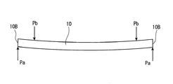
このような搬入および搬出である搬送中期における搬送ローラ530およびガイド部材520による光ディスク10の挟持状態を図5ないし図8に基づいて、詳しく説明する。なお、図7には、図5における囲み部Aが拡大して示されている。この図5〜図8において、搬送ローラ530は、回動部材534に設けられたコイルばね534Bによって上方に付勢され、第2案内面533で光ディスク10を押圧しており、第2案内面533から光ディスク10に対して挟持力Paが作用している。この搬送ローラ530からの押圧力に釣り合う反力として、ガイド部材520のホルダ523およびガイド524から光ディスク10に対して挟持力Pb(Pb1,Pb2)が作用している。   The holding state of the optical disk 10 by the transport roller 530 and the guide member 520 in the middle of transporting as carry-in and carry-out will be described in detail with reference to FIGS. Note that FIG. 7 shows the encircled portion A in FIG. 5 in an enlarged manner. 5 to 8, the conveying roller 530 is urged upward by a coil spring 534 </ b> B provided on the rotating member 534, and presses the optical disk 10 with the second guide surface 533, and the second guide surface 533. Therefore, a clamping force Pa acts on the optical disc 10. A clamping force Pb (Pb1, Pb2) acts on the optical disc 10 from the holder 523 and the guide 524 of the guide member 520 as a reaction force that balances the pressing force from the transport roller 530.

これらの挟持力Pa,Pbは、図7に示すように、搬送ローラ530の第2案内面533に光ディスク10の直径方向の外周縁10Bが当接する状態において、第2案内面533からの挟持力Paの作用位置が、ホルダ523およびガイド524からの挟持力Pbの作用位置よりも、搬送方向Tの両側方外側に位置している。これは、第2案内面533の傾斜角度θ2が、ガイド部材520のホルダ523およびガイド524の傾斜角度θ3よりも十分に大きく設定されているために、軟質部材から形成された第2案内面533が変形したとしても、挟持力Paの作用位置が中央側にずれないためである。このような挟持力Pa,Pbが作用することにより、光ディスク10は、記録面側またはレーベル面側に反らない、または図5および図8に示すように、若干量だけ記録面側に凸に反ってレーベル面側に反らないようになっている。   These clamping forces Pa and Pb are the clamping forces from the second guide surface 533 when the outer peripheral edge 10B in the diameter direction of the optical disc 10 is in contact with the second guide surface 533 of the transport roller 530, as shown in FIG. The operation position of Pa is located on the outer sides on both sides in the transport direction T with respect to the operation position of the clamping force Pb from the holder 523 and the guide 524. This is because the inclination angle θ2 of the second guide surface 533 is set to be sufficiently larger than the inclination angle θ3 of the holder 523 of the guide member 520 and the guide 524, and thus the second guide surface 533 formed of a soft member. This is because even if the deformation occurs, the operation position of the clamping force Pa does not shift to the center side. As a result of such clamping forces Pa and Pb acting, the optical disc 10 does not warp on the recording surface side or the label surface side, or protrudes slightly toward the recording surface side as shown in FIGS. It is not warped to the label side.

また、光ディスク10の直径方向の外周縁10Bがガイド部材520のホルダ523またはガイド524に当接する状態において、搬送ローラ530の第2案内面533には、光ディスク10の直径方向の外周よりも中央よりの部分が当接することになる。しかし、この場合でも、ガイド部材520のホルダ523およびガイド524から作用する挟持力Pb1,Pb2の合力であるPbの作用位置は、第2案内面533からの挟持力Paの作用位置よりも中央側に位置している。このため、上述と同様に、光ディスク10は、記録面側またはレーベル面側に反らない、または、若干量だけ記録面側に凸に反ってレーベル面側に反らないようになっている。   Further, in a state where the outer peripheral edge 10B in the diametrical direction of the optical disc 10 is in contact with the holder 523 or the guide 524 of the guide member 520, the second guide surface 533 of the transport roller 530 is closer to the center than the outer periphery in the diametrical direction of the optical disc 10. Will come into contact. However, even in this case, the acting position of Pb, which is the resultant force of the clamping forces Pb 1 and Pb 2 acting from the holder 523 and the guide 524 of the guide member 520, is more central than the acting position of the clamping force Pa from the second guide surface 533. Is located. For this reason, as described above, the optical disk 10 does not warp on the recording surface side or the label surface side, or slightly protrudes toward the recording surface side and does not warp on the label surface side.

このようにして、ターンテーブル222に軸支される位置である挿入完了位置まで光ディスク10が搬入されると、光ディスク10の外周縁10Bが検知手段550の突出ピン551Bから離れ、検知スイッチ552がオフとなる。このオフ信号を受けたシステム制御部は、駆動手段540の搬送モータ541の駆動を制御して、搬送ローラ530を停止させて搬入を終了させる。この搬送モータ541の停止により、回動部材534が搬送ローラ530の前方位置に回動して開口部の内側を塞ぎ、搬送ローラ530が退避位置である下方に移動する。さらに、搬入された光ディスク10が搬入検知手段400の検知スイッチをオンすることで、このオン信号を受けたシステム制御部によって、一対の台座部210が回動され、ターンテーブル222および回転子に光ディスク10が挾持される。これにより、光ディスク10の記録面に記録された各種情報を読み取って出力回路部へ出力する読取処理や、システム制御部からの各種情報を記録面に記録する記録処理が実施可能になる。   In this way, when the optical disc 10 is carried to the insertion completion position, which is a position pivotally supported by the turntable 222, the outer peripheral edge 10B of the optical disc 10 is separated from the protruding pin 551B of the detection means 550, and the detection switch 552 is turned off. It becomes. Upon receiving this OFF signal, the system control unit controls the driving of the transport motor 541 of the drive unit 540, stops the transport roller 530, and ends the carry-in. When the transport motor 541 stops, the rotating member 534 rotates to the front position of the transport roller 530 and closes the inside of the opening, and the transport roller 530 moves downward as the retreat position. Further, when the loaded optical disk 10 turns on the detection switch of the loading detection means 400, the pair of pedestals 210 are rotated by the system control unit that has received this ON signal, and the optical disk 10 is turned to the turntable 222 and the rotor. 10 is held. Accordingly, it is possible to perform a reading process of reading various information recorded on the recording surface of the optical disc 10 and outputting the information to the output circuit unit, and a recording process of recording various information from the system control unit on the recording surface.

次に、例えば光ディスク10の排出を要求するイジェクトボタンなどの操作や電気機器からの排出を要求する要求信号をシステム制御部が認識すると、システム制御部は移動用電動モータ310の駆動を制御して、情報処理部240を退避位置へ移動させるとともに、一対の台座部210を回動させて、ターンテーブル222および回転子による光ディスク10の挾持を解除させる。その後、システム制御部は、アーム部420を回動させて光ディスク10を押し出すとともに、ディスク搬送部500の搬送モータ541に指令し、光ディスク10を搬出する方向に搬送モータ541を回転駆動させる。この搬送モータ541の駆動により退避位置の搬送ローラ530が上方の搬送位置に移動し、回動部材534が搬送ローラ530の前方の斜め下方位置に回動して搬送経路が形成される。そして、搬送ローラ530とガイド部材520とで挟持された光ディスク10が搬送ローラ530の回転によりケース体110内から開口部を介して搬出される。搬出された光ディスク10の外周縁10Bが検知手段550の突出ピン551Bから離れ、検知スイッチ552がオフとなると、オフ信号を受けたシステム制御部は、搬送モータ541の駆動を制御して、搬送ローラ530を停止させて搬出を終了させる。   Next, for example, when the system control unit recognizes a request signal for requesting ejection from the electric device or an operation of an eject button that requests ejection of the optical disc 10, the system control unit controls driving of the electric motor 310 for movement. The information processing unit 240 is moved to the retracted position, and the pair of pedestal units 210 are rotated to release the holding of the optical disk 10 by the turntable 222 and the rotor. Thereafter, the system control unit rotates the arm unit 420 to push out the optical disk 10 and instructs the transport motor 541 of the disk transport unit 500 to rotate the transport motor 541 in the direction of unloading the optical disk 10. By driving the transport motor 541, the transport roller 530 at the retracted position moves to the upper transport position, and the rotation member 534 rotates to an obliquely lower position in front of the transport roller 530 to form a transport path. Then, the optical disc 10 sandwiched between the transport roller 530 and the guide member 520 is unloaded from the case body 110 through the opening by the rotation of the transport roller 530. When the outer peripheral edge 10B of the unloaded optical disk 10 is separated from the projecting pin 551B of the detection means 550 and the detection switch 552 is turned off, the system control unit that has received the off signal controls the drive of the transport motor 541 to control the transport roller. 530 is stopped and the carrying out is finished.

このようにして、光ディスク10が搬出される搬出中期において、前述の図5ないし図8に示した場合と同様に、光ディスク10は、その直径方向の外周縁10B近傍が搬送ローラ530の第2案内面533と、ガイド部材520のホルダ523およびガイド524との間に挟持される。そして、前述と同様に光ディスク10は、記録面側またはレーベル面側に反らない、または、若干量だけ記録面側に凸に反ってレーベル面側に反らないようになっている。   In this way, in the middle of unloading when the optical disk 10 is unloaded, as in the case shown in FIGS. 5 to 8 described above, the optical disk 10 has the second guide of the transport roller 530 in the vicinity of the outer peripheral edge 10B in the diameter direction. It is sandwiched between the surface 533 and the holder 523 and the guide 524 of the guide member 520. In the same manner as described above, the optical disc 10 does not warp on the recording surface side or the label surface side, or slightly warps on the recording surface side and does not warp on the label surface side.

(第1の実施の形態における作用効果)
上述したように、上記第1の実施の形態では、光ディスク10を搬送する搬送中期において、光ディスク10の直径方向近傍の外周縁10Bが搬送ローラ530の第2案内面533とガイド部材520のホルダ523およびガイド524とで挟持され、第2案内面533からの挟持力Paの作用位置が、ホルダ523およびガイド524からの挟持力Pbの作用位置よりも、搬送方向Tの両側方外側に位置している。このため、光ディスク10は、記録面側またはレーベル面側に反らない、または図5および図8に示すように、若干量だけ記録面側に凸に反ってレーベル面側に反らないようになっている。したがって、光ディスク10のレーベル面がガイド部材520やその他のディスク搬送部500の各部に擦ることがなく、レーベル面の表面の傷を防止して光ディスク10を良好に搬送することができる。
(Operational effects in the first embodiment)
As described above, in the first embodiment, the outer peripheral edge 10B in the vicinity of the diameter direction of the optical disk 10 is the second guide surface 533 of the transport roller 530 and the holder 523 of the guide member 520 in the middle of transport of the optical disk 10. And the operation position of the clamping force Pa from the second guide surface 533 is positioned on both outer sides in the transport direction T from the operation position of the clamping force Pb from the holder 523 and the guide 524. Yes. For this reason, the optical disc 10 does not warp on the recording surface side or the label surface side, or, as shown in FIGS. 5 and 8, it slightly protrudes toward the recording surface side and does not warp on the label surface side. It has become. Therefore, the label surface of the optical disk 10 does not rub against the guide member 520 or other parts of the disk transport unit 500, and the optical disk 10 can be transported satisfactorily by preventing scratches on the surface of the label surface.

また、搬送ローラ530における第2案内面533の母線の回転軸531に対する傾斜角度θ2を、ガイド部材520におけるホルダ523の傾斜角度θ3よりも十分に大きく(θ2>θ3)設定している。このため、軟質部材から形成された第2案内面533が弾性変形した場合でも、第2案内面533からの挟持力Paの作用位置がホルダ523およびガイド524からの挟持力Pbの作用位置よりも、光ディスク10の搬送方向Tに交差する内側に大きくずれることが防止でき、光ディスク10がレーベル面側に反ることが確実に防止できる。   In addition, the inclination angle θ2 of the second guide surface 533 of the transport roller 530 with respect to the rotation axis 531 is set sufficiently larger than the inclination angle θ3 of the holder 523 of the guide member 520 (θ2> θ3). For this reason, even when the second guide surface 533 formed of a soft member is elastically deformed, the operating position of the clamping force Pa from the second guide surface 533 is more than the operating position of the clamping force Pb from the holder 523 and the guide 524. Further, it is possible to prevent the optical disk 10 from being greatly displaced inwardly intersecting the transport direction T of the optical disk 10 and to reliably prevent the optical disk 10 from warping to the label surface side.

以上のようにレーベル面の傷が防止されることで、特にディスク状記録媒体がDVD(Digital Versatile Disc)である場合には、レーベル面に保護膜(コーティング)が施されていないことがあり、レーベル面が傷つきやすくなっていることから有効である。また、両面記録型のDVD等の場合には、上記レーベル面も記録面であり、各種情報が記録されているため、傷がつくと情報が適正に読み出せなかったり、また情報が記録できなくなったりするという不都合が生じるため、レーベル面の傷を防止することでこのような不都合が生じないようにできる。   By preventing scratches on the label surface as described above, particularly when the disc-shaped recording medium is a DVD (Digital Versatile Disc), a protective film (coating) may not be applied to the label surface. This is effective because the label surface is easily damaged. Further, in the case of a double-sided recording type DVD or the like, the label surface is also a recording surface, and various information is recorded. Therefore, if a scratch is made, the information cannot be read properly or information cannot be recorded. Therefore, it is possible to prevent such inconvenience by preventing scratches on the label surface.

また、搬送ローラ530における第1および第2の案内面532,533の母線、およびガイド部材520におけるホルダ523が回転軸531に対して所定の傾斜角度θ1,θ2,θ3だけ傾斜している。このため、これらで光ディスク10の外周縁10Bに当接を挟持することができ、搬送初期や後期においても光ディスク10の記録面やレーベル面に傷をつけることなく良好に搬送することができる。   In addition, the buses of the first and second guide surfaces 532 and 533 in the transport roller 530 and the holder 523 in the guide member 520 are inclined at predetermined inclination angles θ1, θ2, and θ3 with respect to the rotation shaft 531. For this reason, the contact can be held between the outer peripheral edge 10B of the optical disc 10 and the recording can be carried well without damaging the recording surface or the label surface of the optical disc 10 even in the early stage or later stage.

さらに、搬送ローラ530の第1および第2の案内面532,533が軟質部材にて形成されている。このため、光ディスク10の搬送を確実に実行できるとともに、これらの案内面532,533が光ディスク10の記録面を傷つける可能性はより低くなっている。さらに、搬送ローラ530の回転により第1および第2の案内面532,533は、光ディスク10の記録面に対して転動するので、記録面に傷をつける可能性をより一層低くすることができる。   Further, the first and second guide surfaces 532 and 533 of the transport roller 530 are formed of a soft member. For this reason, the conveyance of the optical disk 10 can be reliably executed, and the possibility that these guide surfaces 532 and 533 damage the recording surface of the optical disk 10 is lower. Further, since the first and second guide surfaces 532 and 533 roll with respect to the recording surface of the optical disc 10 by the rotation of the conveying roller 530, the possibility of scratching the recording surface can be further reduced. .

また、搬送ローラ530は、コイルばね534Bによってガイド部材620に向けて付勢されている。このため、この付勢力により光ディスク10を所定の挟持力で挟持することができ、光ディスク10の搬送を確実に実施することができる。   Further, the transport roller 530 is biased toward the guide member 620 by a coil spring 534B. For this reason, the optical disk 10 can be clamped with a predetermined clamping force by this urging force, and the optical disk 10 can be reliably transported.

さらに、挿入完了位置まで光ディスク10を搬入した後に、搬送ローラ530が回動して退避位置に下がる。このため、ターンテーブル222にて回転駆動される光ディスク10が万一にも搬送ローラ530に接触することを防止でき、光ディスク10に対する読取処理や記録処理を確実に実施できる。   Further, after the optical disk 10 is carried to the insertion completion position, the transport roller 530 is rotated and lowered to the retracted position. For this reason, it is possible to prevent the optical disk 10 that is rotationally driven by the turntable 222 from coming into contact with the transport roller 530, and the reading process and the recording process for the optical disk 10 can be reliably performed.

また、光ディスク10の搬入後に、回動部材534が搬送ローラ530の前方位置に回動して開口部の内側を塞ぐ構成としている。このため、ケース体110内へゴミや埃等が入り込むことが防止できるとともに、利用者が誤って新たな光ディスク10を挿入しようとしても回動部材534にぶつかって挿入できなくすることで、ディスク装置100の誤動作や故障が防止できる。   Further, after the optical disk 10 is carried in, the rotation member 534 is rotated to the front position of the transport roller 530 to block the inside of the opening. For this reason, it is possible to prevent dust, dust, etc. from entering the case body 110, and even if the user tries to insert a new optical disk 10 by mistake, the user can hit the rotating member 534 so that it cannot be inserted. 100 malfunctions and failures can be prevented.

また、光ディスク10の挿入を検知する検知手段550を設けている。このため、光ディスク10がガイド部材520と搬送ローラ530との間に押し込まれると、即座にこれを検知して駆動手段540の搬送モータ541が駆動され、搬送ローラ530が回転駆動されて光ディスク10の搬入を開始させることができる。したがって、利用者は光ディスク10を所定位置まで押し込むだけで、自動的に光ディスク10が搬入されるので、利便性を向上させることができる。   Further, a detecting means 550 for detecting insertion of the optical disc 10 is provided. For this reason, when the optical disk 10 is pushed between the guide member 520 and the transport roller 530, this is immediately detected and the transport motor 541 of the driving means 540 is driven, and the transport roller 530 is driven to rotate. Carrying in can be started. Therefore, since the optical disk 10 is automatically carried in simply by the user pushing the optical disk 10 to a predetermined position, the convenience can be improved.

さらに、光ディスク10が挿入完了位置まで搬入される、あるいは開口部から搬出されると、これを検知手段550で検知して搬送モータ541の駆動が停止され、搬入または搬出が完了する。このため、利便性を一層向上させることができる。   Further, when the optical disc 10 is carried to the insertion completion position or taken out from the opening, this is detected by the detection means 550, and the drive of the carry motor 541 is stopped, and the carry-in or carry-out is completed. For this reason, the convenience can be further improved.

また、検知手段550をディスク搬送部500の長手方向左右両側に設けている。このため、これら左右両側の検知スイッチ552がオンしなければ搬送モータ541を駆動しないように制御することで、光ディスク10が開口部の左右いずれかに偏って挿入された場合には、搬入開始しないようにもでき、適切な位置に光ディスク10を挿入するように利用者に知らせることができる。この際、開口部の左右いずれかに若干偏って光ディスク10を挿入した場合には、少し奥まで押し込むことで、左右両側の検知スイッチ552がオンするため、光ディスク10の搬入が開始され、利便性が損なわれることがないようにできる。   Further, the detection means 550 is provided on both the left and right sides of the disk transport unit 500 in the longitudinal direction. For this reason, if the detection switches 552 on both the left and right sides are not turned on, the conveyance motor 541 is controlled so as not to be driven. The user can be informed to insert the optical disc 10 at an appropriate position. At this time, when the optical disc 10 is inserted slightly biased to either the left or right of the opening, the detection switches 552 on both the left and right sides are turned on by pushing in slightly, so that the loading of the optical disc 10 is started and the convenience is increased. Can be prevented from being damaged.

〔第2の実施の形態〕
次に、本発明における第2の実施の形態を図面に基づいて説明する。
[Second Embodiment]
Next, a second embodiment of the present invention will be described with reference to the drawings.

(ディスク装置の構成)
図9は、第2の実施の形態に係るディスク装置におけるディスク搬送部を示す一部を切り欠いた正面図である。図10は、ディスク搬送部による光ディスクの搬送状態を示す正面から見た説明図である。図11は、ディスク搬送部による光ディスクの搬送状態を示す上面から見た説明図である。図12はディスク搬送部の検知手段の動作を示す説明図で、(A)はディスク搬送部近傍の正面図、(B)はディスク搬送部の平面図である。なお、第1の実施の形態と同一の構成については、同一の符号を付して説明を省略または簡略化する。
(Disk unit configuration)
FIG. 9 is a front view in which a part of the disk transport unit in the disk device according to the second embodiment is cut away. FIG. 10 is an explanatory diagram viewed from the front showing the state of the optical disk transported by the disk transport unit. FIG. 11 is an explanatory diagram viewed from the top showing the state of the optical disk transported by the disk transport section. 12A and 12B are explanatory views showing the operation of the detection means of the disk transport unit, where FIG. 12A is a front view of the vicinity of the disk transport unit, and FIG. 12B is a plan view of the disk transport unit. In addition, about the structure same as 1st Embodiment, the same code | symbol is attached | subjected and description is abbreviate | omitted or simplified.

図9において、搬送装置としてのディスク搬送部600は、第1の実施の形態と同様のディスク装置100のケース体110に配設されるもので、第1の実施の形態と同様の支持部材610と、ガイド部材620と、駆動手段640と、を備えている。すなわち、支持部材610は、上面部611と、前面部612と、側面部613と、を備えて形成されている。また、ガイド部材620は、上面部621と、前面部622と、を備えて形成されており、この前面部622の下端縁には、ガイド部としてのホルダ623が形成され、上面部621の内方端には、案内部材としてのガイド624が形成されている。さらに、駆動手段640は、図示しない搬送モータ641と、伝達機構642と、を備えており、伝達機構642は、図示しない第1ウォームギアと、第2ウォームギア642Bと、第3ウォームギア642Cと、駆動ギア642Dと、を備えている。さらに、搬送手段600は、回転部材としての搬送ローラ630と、光ディスク10の挿入を検知する検知手段650と、を備えており、これらの搬送ローラ630および検知手段650の構成が第1の実施の形態と相違している。以下、相違点について詳しく説明する。   In FIG. 9, a disk transport unit 600 as a transport device is disposed on a case body 110 of a disk device 100 similar to that of the first embodiment, and a support member 610 similar to that of the first embodiment. And a guide member 620 and a drive means 640. That is, the support member 610 includes an upper surface portion 611, a front surface portion 612, and a side surface portion 613. The guide member 620 includes an upper surface portion 621 and a front surface portion 622, and a holder 623 serving as a guide portion is formed on the lower end edge of the front surface portion 622. A guide 624 as a guide member is formed at the end. Furthermore, the drive means 640 includes a transport motor 641 and a transmission mechanism 642 (not shown). The transmission mechanism 642 includes a first worm gear, a second worm gear 642B, a third worm gear 642C, and a drive gear (not shown). 642D. Further, the transport unit 600 includes a transport roller 630 as a rotating member, and a detection unit 650 that detects insertion of the optical disc 10, and the configuration of the transport roller 630 and the detection unit 650 is the first embodiment. It is different from the form. Hereinafter, the differences will be described in detail.

搬送ローラ630は、搬送方向Tに対して直交する方向に回転軸631を有して回転可能に配設されている。搬送ローラ630は、回転軸631と同軸に設けられたスライド軸632と、このスライド軸632に沿って搬送方向Tに直交する方向にスライド自在に設けられた一対のローラ633と、を備えている。スライド軸632は、円柱ではない断面形(例えば、+字形や−字形、多角形、楕円形、長円形等)を有し、一対のローラ633をスライド軸632に対して回転不能に、かつスライド移動可能に支持している。一対のローラ633は、スライド軸632が挿通される図示しない挿通孔と、互いに対向する一端部に対して反対側の他端部側が他端部に向けて次第に径大に形成されたの傾斜領域としての案内面633Aと、を備えている。この案内面633Aは、弾性変形可能な軟質部材から形成され、挿入された光ディスク10の外周縁に記録面側から当接するようになっている。この案内面633Aの母線の回転軸631に対する傾斜角度は、8.0°に設定され、ガイド部材620のホルダ523の傾斜角度よりも大きく設定されている。なお、案内面633Aの傾斜角度は、上記に限らず、5.0°以上10°以下の範囲で、好ましくは、7.0°以上9.0°以下の範囲で設定可能である。   The transport roller 630 has a rotation shaft 631 in a direction orthogonal to the transport direction T and is rotatably disposed. The transport roller 630 includes a slide shaft 632 provided coaxially with the rotation shaft 631 and a pair of rollers 633 provided so as to be slidable in a direction perpendicular to the transport direction T along the slide shaft 632. . The slide shaft 632 has a non-cylindrical cross-sectional shape (for example, a + -shape, a -shape, a polygon, an ellipse, an oval, etc.), and the pair of rollers 633 cannot slide with respect to the slide shaft 632 and slide. Supports movable. The pair of rollers 633 includes an insertion hole (not shown) through which the slide shaft 632 is inserted, and an inclined region in which the other end on the opposite side to the one end facing each other is gradually increased in diameter toward the other end. As a guide surface 633A. The guide surface 633A is formed of an elastically deformable soft member, and comes into contact with the outer peripheral edge of the inserted optical disk 10 from the recording surface side. An inclination angle of the bus of the guide surface 633A with respect to the rotation axis 631 is set to 8.0 °, and is set to be larger than an inclination angle of the holder 523 of the guide member 620. The inclination angle of the guide surface 633A is not limited to the above, and can be set in the range of 5.0 ° to 10 °, and preferably in the range of 7.0 ° to 9.0 °.

また、図10に示すように、搬送ローラ630には、一対のローラ633を互いに近づける方向に付勢する移動規制部材としてのばね部材635が設けられている。このばね部材635は、一対のローラ633の両端外方から内方に向かってローラ633を押圧するコイルばね等から構成されてもよく、また一対のローラ633の対向内側にローラ633を引っ張るコイルばね等から構成されてもよい。これにより、一対のローラ633は、挿入された光ディスク10に向かって付勢され、図11に示すように、搬送時の光ディスク10の搬送方向Tに直交する幅寸法に応じてスライドするようになっている。搬送ローラ630の回転軸631両端は、第1の実施の形態と同様の回動部材634に軸支されている。この回動部材634は、その両端部634Aが支持部材610の側面部613に軸支され、搬送ローラ630の前方から前方の斜め下方までに渡って回動可能になっている。そして、回動部材634の一方の端部と支持部材610との間には、コイルばね634Bが架設されており、このコイルばね634Bによって回動部材634が、搬送ローラ530の前方または前方の斜め下方のいずれかの位置に付勢されるようになっている。搬送ローラ630は、回動部材634の回動に伴って回動し、光ディスク10を挟持可能な搬送位置と、光ディスク10を挟持しない退避位置との間を上下に移動するようになっている。搬送位置において、搬送ローラ630は、コイルばね634Bによってガイド部材620に向かって付勢されている。   Further, as shown in FIG. 10, the conveying roller 630 is provided with a spring member 635 as a movement restricting member that urges the pair of rollers 633 toward each other. The spring member 635 may be constituted by a coil spring or the like that presses the roller 633 from the outside to the inside of both ends of the pair of rollers 633, and the coil spring that pulls the roller 633 inside the pair of rollers 633. Or the like. As a result, the pair of rollers 633 is biased toward the inserted optical disk 10 and slides according to the width dimension orthogonal to the transport direction T of the optical disk 10 during transport, as shown in FIG. ing. Both ends of the rotation shaft 631 of the transport roller 630 are pivotally supported by a rotation member 634 similar to that of the first embodiment. Both end portions 634A of the rotating member 634 are pivotally supported by the side surface portion 613 of the support member 610, and can be rotated from the front of the conveying roller 630 to the diagonally lower front. A coil spring 634B is installed between one end of the rotation member 634 and the support member 610. The coil spring 634B causes the rotation member 634 to be inclined forward or forward of the transport roller 530. It is biased to any position below. The transport roller 630 rotates with the rotation of the rotation member 634 and moves up and down between a transport position where the optical disk 10 can be sandwiched and a retracted position where the optical disk 10 is not sandwiched. At the transport position, the transport roller 630 is biased toward the guide member 620 by the coil spring 634B.

また、図12に示すように、搬送手段600の検知手段650は、一対のローラ633の移動に連動する連動部654と、この連動部654の動作によりオンオフする検知スイッチ652と、を備えている。連動部654は、例えばローラ633の移動に伴って回動するアームでもよく、またローラ633の移動に伴ってスライドするスライダでもよい。すなわち、連動部654としては、ローラ633の移動を検知スイッチ652に伝達するものであれば、いずれの構成でも採用可能である。そして、光ディスク10が挿入されると、一対のローラ633が搬送方向Tに直交する左右外側に押し広げられて移動し、検知スイッチ652がオンとなり、光ディスク10の挿入が検知される。さらに、光ディスク10がターンテーブルに軸支される位置まで搬入された状態、またはケース体110外に搬出された状態において、一対のローラ633が長手方向中央側に戻ることで、検知スイッチ652がオフとなる。この検知スイッチ652のオンオフ信号は、システム制御部へ出力され、このオンオフ信号に基づいて、システム制御部は、駆動手段640の搬送モータを駆動または停止させるように制御する。   As shown in FIG. 12, the detection unit 650 of the transport unit 600 includes an interlocking unit 654 that is interlocked with the movement of the pair of rollers 633, and a detection switch 652 that is turned on / off by the operation of the interlocking unit 654. . The interlocking unit 654 may be an arm that rotates as the roller 633 moves, or may be a slider that slides as the roller 633 moves. That is, as the interlocking unit 654, any configuration can be employed as long as it transmits the movement of the roller 633 to the detection switch 652. When the optical disk 10 is inserted, the pair of rollers 633 are pushed and moved outward in the right and left directions perpendicular to the transport direction T, the detection switch 652 is turned on, and the insertion of the optical disk 10 is detected. Further, when the optical disk 10 is loaded to a position where it is pivotally supported by the turntable or is unloaded from the case body 110, the pair of rollers 633 return to the center in the longitudinal direction, whereby the detection switch 652 is turned off. It becomes. The on / off signal of the detection switch 652 is output to the system control unit, and based on the on / off signal, the system control unit controls to drive or stop the transport motor of the driving unit 640.

(ディスク装置の動作)
次に、上記第2の実施の形態におけるディスク装置100の動作を説明する。ディスク装置100全体の動作は、前記第1の実施の形態と略同一であるため説明を省略し、ディスク搬送部600の動作について説明する。
(Disk unit operation)
Next, the operation of the disk device 100 in the second embodiment will be described. Since the operation of the entire disk device 100 is substantially the same as that of the first embodiment, the description thereof will be omitted, and the operation of the disk transport unit 600 will be described.

まず、光ディスク10が装填されていない状態では、ディスク搬送部600の回動部材634が搬送ローラ630の前方の斜め下方位置に回動し、搬送ローラ630が搬送位置である上方に移動し、一対のローラ633が長手方向中央側に位置した挿入待機状態になっている。この挿入待機状態で光ディスク10が開口部からガイド部材620と搬送ローラ630との間に挿入されると、光ディスク10の周縁が一対のローラ633の案内面633Aに当接する。この状態でさらに光ディスク10が押し込まれると、一対のローラ633がばね部材635の付勢力に抗して外側へ押し出される。そして、光ディスク10がある程度まで押し込まれると、検知スイッチ652がオンとなり、光ディスク10が挿入されたことをシステム制御部が検知する。   First, in a state in which the optical disk 10 is not loaded, the rotating member 634 of the disk transport unit 600 rotates to an obliquely lower position in front of the transport roller 630, and the transport roller 630 moves upward, which is the transport position. The roller 633 is in an insertion standby state in which the roller 633 is positioned on the center side in the longitudinal direction. When the optical disc 10 is inserted between the guide member 620 and the transport roller 630 from the opening in this insertion standby state, the periphery of the optical disc 10 contacts the guide surfaces 633A of the pair of rollers 633. When the optical disk 10 is further pushed in this state, the pair of rollers 633 are pushed outward against the urging force of the spring member 635. When the optical disk 10 is pushed to a certain extent, the detection switch 652 is turned on, and the system control unit detects that the optical disk 10 has been inserted.

光ディスク10の挿入を検知したシステム制御部は、駆動手段640の搬送モータ641に指令し、光ディスク10を搬入する方向に搬送モータ641を回転駆動させる。この搬送モータ641の駆動が伝達機構642を介して回転軸631に伝達され、スライド軸632とともに一対のローラ633が回転する。この回転により、一対のローラ633とガイド部材620とで挟持された光ディスク10がケース体110内へ搬入される。そして、光ディスク10の搬入に伴って一対のローラ633は、光ディスク10の外周縁10Bに沿って搬入方向Tに直交する方向にスライドする。従って、光ディスク10は、その外周縁10Bが一対のローラ633の案内面633Aと、ガイド部材620のホルダ623およびガイド624との間に挟持され、ターンテーブルに軸支される位置まで搬入される。   The system control unit that has detected the insertion of the optical disk 10 instructs the transport motor 641 of the driving unit 640 to rotate the transport motor 641 in the direction in which the optical disk 10 is loaded. The drive of the conveyance motor 641 is transmitted to the rotating shaft 631 via the transmission mechanism 642, and the pair of rollers 633 rotate together with the slide shaft 632. By this rotation, the optical disc 10 sandwiched between the pair of rollers 633 and the guide member 620 is carried into the case body 110. The pair of rollers 633 slide along the outer peripheral edge 10 </ b> B of the optical disk 10 in a direction orthogonal to the loading direction T as the optical disk 10 is loaded. Therefore, the optical disk 10 is carried to the position where the outer peripheral edge 10B is sandwiched between the guide surface 633A of the pair of rollers 633, the holder 623 and the guide 624 of the guide member 620, and is pivotally supported by the turntable.

以上のような一対のローラ633およびガイド部材620による光ディスク10の挟持状態は、前記第1の実施の形態と略同様に、ローラ633の案内面633Aから光ディスク10に作用する挟持力の作用位置が、ガイド部材620のホルダ623およびガイド624から光ディスク10に作用する挟持力の作用位置よりも、搬送方向Tの両側方外側に位置している。このように挟持力が作用することにより、光ディスク10は、記録面側またはレーベル面側に反らない、または図10に示すように、若干量だけ記録面側に凸に反ってレーベル面側に反らないようになっている。一方、光ディスク10の搬出時においても上述と同様に、光ディスク10は、一対のローラ633とガイド部材620とで挟持されて、レーベル面側に反らないようになっている。   The sandwiching state of the optical disk 10 by the pair of rollers 633 and the guide member 620 as described above is substantially the same as in the first embodiment, in which the position of the sandwiching force acting on the optical disk 10 from the guide surface 633A of the roller 633 is determined. The guide member 620 is located on both sides in the transport direction T from the position where the holding force acting on the optical disk 10 from the holder 623 and the guide 624 is applied. As a result of the clamping force acting in this way, the optical disc 10 does not warp on the recording surface side or the label surface side, or, as shown in FIG. It does not warp. On the other hand, even when the optical disk 10 is unloaded, the optical disk 10 is sandwiched between the pair of rollers 633 and the guide member 620 so as not to bend toward the label surface side, as described above.

(第2の実施の形態における作用効果)
上述したように、上記第2の実施の形態では、光ディスク10の搬送時において、光ディスク10の外周縁10Bが一対のローラ633の案内面633Aとガイド部材620のホルダ623およびガイド624とで挟持され、案内面633Aからの挟持力の作用位置が、ホルダ623およびガイド624からの挟持力の作用位置よりも、搬送方向Tの両側方外側に位置している。このため、光ディスク10は、記録面側またはレーベル面側に反らない、または若干量だけ記録面側に凸に反ってレーベル面側に反らないようになっている。したがって、光ディスク10のレーベル面がガイド部材620やその他のディスク搬送部600の各部に擦ることがなく、レーベル面の表面の傷を防止して光ディスク10を良好に搬送することができる。
(Operational effects in the second embodiment)
As described above, in the second embodiment, when the optical disc 10 is transported, the outer peripheral edge 10B of the optical disc 10 is sandwiched between the guide surface 633A of the pair of rollers 633 and the holder 623 and guide 624 of the guide member 620. The position where the clamping force is applied from the guide surface 633A is located on the outer sides on both sides in the transport direction T with respect to the position where the clamping force is applied from the holder 623 and the guide 624. For this reason, the optical disk 10 does not warp on the recording surface side or the label surface side, or slightly protrudes toward the recording surface side and does not warp on the label surface side. Therefore, the label surface of the optical disk 10 does not rub against the guide member 620 and other parts of the disk transport unit 600, and the optical disk 10 can be transported satisfactorily by preventing scratches on the surface of the label surface.

また、一対のローラ633における案内面633Aの母線の回転軸631に対する傾斜角度を、ガイド部材620におけるホルダ623やガイド624の傾斜角度よりも十分に大きく設定している。このため、軟質部材から形成された案内面633Aが弾性変形した場合でも、案内面633Aからの挟持力の作用位置がホルダ623およびガイド624からの挟持力の作用位置よりも、光ディスク10の搬送方向Tに交差する内側に大きくずれることが防止でき、光ディスク10がレーベル面側に反ることが確実に防止できる。   In addition, the inclination angle of the generatrix of the guide surface 633A of the pair of rollers 633 with respect to the rotation shaft 631 is set to be sufficiently larger than the inclination angles of the holder 623 and the guide 624 in the guide member 620. For this reason, even when the guide surface 633A formed of a soft member is elastically deformed, the operation position of the clamping force from the guide surface 633A is more than the operation position of the clamping force from the holder 623 and the guide 624. Therefore, it is possible to prevent the optical disk 10 from warping to the label surface side.

さらに、一対のローラ633がスライド軸632に沿って移動する。このため、搬送時の光ディスク10の搬送方向Tに直交する幅寸法に応じて一対のローラ633の間隔距離が変化し、搬送時には常に光ディスク10の外周縁10Bにローラ633の案内面633Aを当接させることができ、光ディスク10の搬送状態を一層良好にすることができる。   Further, the pair of rollers 633 moves along the slide shaft 632. For this reason, the distance between the pair of rollers 633 changes according to the width dimension orthogonal to the transport direction T of the optical disk 10 during transport, and the guide surface 633A of the roller 633 is always in contact with the outer peripheral edge 10B of the optical disk 10 during transport. The conveyance state of the optical disk 10 can be further improved.

また、光ディスク10の挿入を検知する検知手段650を一対のローラ633の移動を検知するように構成している。このため、ローラ633の他にスライド部材等を設ける必要がなく、ディスク搬送部600の構造を簡単にして、ディスク装置100のさらなる小型化や薄型化を図ることができる。   Further, the detecting means 650 for detecting the insertion of the optical disk 10 is configured to detect the movement of the pair of rollers 633. Therefore, there is no need to provide a slide member or the like in addition to the roller 633, the structure of the disk transport unit 600 can be simplified, and the disk device 100 can be further reduced in size and thickness.

〔実施形態の変形〕
なお、本発明は、上述した各実施の形態に限定されるものではなく、本発明の目的を達成できる範囲で以下に示される変形をも含むものである。
[Modification of Embodiment]
In addition, this invention is not limited to each embodiment mentioned above, The deformation | transformation shown below is included in the range which can achieve the objective of this invention.

すなわち、ディスク状記録媒体を利用するディスク装置100について例示したが、上述したように、光ディスク10に限らず、磁気ディスク、光磁気ディスクなどのいずれのディスク状記録媒体を対象とすることができる。また、読取処理あるいは記録処理の一方のみを処理する構成のものにも適用できる。さらには、電気機器に組み込まれる構成に限らず、単体として構成したものでもよい。また、ディスク装置100内に搭載する回路基板としたシステム制御部として、1つの素子やプログラム構成とするなどしてもよい。   That is, the disk device 100 using the disk-shaped recording medium has been exemplified, but as described above, any disk-shaped recording medium such as a magnetic disk or a magneto-optical disk can be used as a target, not limited to the optical disk 10. Further, the present invention can be applied to a configuration in which only one of reading processing and recording processing is processed. Furthermore, it is not limited to a configuration incorporated in an electric device, but may be configured as a single unit. Further, as a system control unit that is a circuit board mounted in the disk device 100, one element or a program configuration may be used.

また、ディスク処理部200の構成は、回動可能な一対の台座部210を備えたものに限らず、ケース体110内に固定されたフレームを備え、このフレームに対して移動あるいは回動可能な台座部が支持され、この台座部にディスク回転駆動手段220や情報処理部240が配設された構成のものでもよい。   Further, the configuration of the disk processing unit 200 is not limited to the one provided with the pair of pedestal portions 210 that can be rotated, but includes a frame fixed in the case body 110 and can be moved or rotated with respect to the frame. A structure in which a pedestal part is supported and the disk rotation driving means 220 and the information processing part 240 are disposed on the pedestal part may be used.

さらに、第1の実施の形態において、ディスク搬送部500の搬送ローラ530を第1および第2の案内面532,533を有して構成したが、これらの案内面は、円錐台状に形成されたものに限らず、搬送ローラの長手中央から両端部に向かって曲面状に径が大きくなるように形成されてもよい。このようにすれば、光ディスク10の搬送途中において、その外周縁が当接する案内面の径が急激に変化しないので、光ディスク10の搬送をより一層円滑に実施することができるようになる。   Furthermore, in the first embodiment, the transport roller 530 of the disk transport unit 500 is configured to include the first and second guide surfaces 532 and 533, but these guide surfaces are formed in a truncated cone shape. However, the present invention is not limited to this, and it may be formed so that the diameter increases in a curved shape from the longitudinal center of the conveying roller toward both ends. In this way, since the diameter of the guide surface with which the outer periphery abuts does not change abruptly during the conveyance of the optical disc 10, the conveyance of the optical disc 10 can be carried out more smoothly.

また、各実施の形態において、案内部材としてのガイド524,624をガイド部材520,620に一体に形成したが、これに限らず、別体に形成した案内部材をガイド部材や支持部材に固定する構成としてもよい。さらに、案内部材は、ガイド部であるホルダ523,623と同様の傾斜面を有して形成されたものに限らず、搬送ローラの回転軸に平行に形成されていてもよい。また、案内部材は、搬送方向に交差した方向に連続的に形成されたものに限らず、単一または複数の突起状に形成されていてもよい。   In each embodiment, the guides 524 and 624 as guide members are formed integrally with the guide members 520 and 620. However, the present invention is not limited to this, and the guide member formed separately is fixed to the guide member or the support member. It is good also as a structure. Furthermore, the guide member is not limited to the one formed with the same inclined surface as the holders 523 and 623 which are guide portions, and may be formed in parallel to the rotation axis of the transport roller. Moreover, the guide member is not limited to the one continuously formed in the direction intersecting the transport direction, and may be formed in a single or a plurality of protrusions.

その他、本発明の実施の際の具体的な構造および手順は、本発明の目的を達成できる範囲で他の構造などに適宜変更できる。   In addition, the specific structure and procedure for carrying out the present invention can be appropriately changed to other structures and the like within a range in which the object of the present invention can be achieved.

〔実施の形態の効果〕
上述したように、光ディスク10を搬送する搬送装置であるディスク搬送部500,600において、搬送ローラ530,630の案内面532,533,633Aが軟質部材で形成され、その軸方向の両端部における案内面533の傾斜角度が中間部における案内面532の傾斜角度より大きく形成され、あるいは光ディスク10の搬送するにしたがって互いに近づいたり離れたりする一対のローラ633の案内面633Aの傾斜角度が大きく形成されているので、案内面533,633Aとホルダ523,623とで挟持された光ディスク10において、案内面533,633Aからの挟持力の作用位置が、ホルダ523,623からの挟持力の作用位置よりも、搬送方向Tの両側方外側に位置している。このため、光ディスク10は、記録面側またはレーベル面側に反らない、または若干量だけ記録面側に凸に反ってレーベル面側に反らない。したがって、光ディスク10のレーベル面がガイド部材520,620などに擦ることがなく、レーベル面の表面の傷を防止して光ディスク10を良好に搬送できる。
[Effect of the embodiment]
As described above, the guide surfaces 532, 533, and 633A of the transport rollers 530 and 630 are formed of soft members in the disk transport units 500 and 600 that are transport devices for transporting the optical disk 10, and guides are provided at both ends in the axial direction. The inclination angle of the surface 533 is formed to be larger than the inclination angle of the guide surface 532 in the intermediate portion, or the inclination angle of the guide surface 633A of the pair of rollers 633 that move toward and away from each other as the optical disk 10 is conveyed. Therefore, in the optical disc 10 sandwiched between the guide surfaces 533 and 633A and the holders 523 and 623, the operation position of the sandwiching force from the guide surfaces 533 and 633A is more than the operation position of the sandwiching force from the holders 523 and 623. It is located on both outer sides in the transport direction T. For this reason, the optical disc 10 does not warp on the recording surface side or the label surface side, or does not warp on the recording surface side by a slight amount but on the label surface side. Therefore, the label surface of the optical disk 10 does not rub against the guide members 520 and 620, and the optical disk 10 can be transported satisfactorily by preventing scratches on the surface of the label surface.

本発明における第1の実施の形態に係るディスク装置の概略構成を示す一部を切り欠いた平面図である。1 is a plan view with a part cut away showing a schematic configuration of a disk device according to a first embodiment of the present invention; 前記第1の実施の形態におけるディスク装置の概略構成を示す一部を切り欠いた平面図であり、光ディスクの略半分が挿入された状態を説明する図である。FIG. 2 is a plan view showing a schematic configuration of the disk device according to the first embodiment with a part cut away, and is a view for explaining a state in which substantially half of the optical disk is inserted. 前記第1の実施の形態におけるディスク装置のディスク搬送部を示す一部を切り欠いた平面図である。FIG. 3 is a plan view with a part cut away showing a disk transport portion of the disk device in the first embodiment. 前記第1の実施の形態におけるディスク搬送部を示す一部を切り欠いた正面図である。It is the front view which notched a part which shows the disc conveyance part in the said 1st Embodiment. 前記第1の実施の形態におけるディスク搬送部による光ディスクの搬送状態を示す正面から見た説明図である。It is explanatory drawing seen from the front which shows the conveyance state of the optical disk by the disk conveyance part in the said 1st Embodiment. 前記第1の実施の形態におけるディスク搬送部による光ディスクの搬送状態を示す側面から見た説明図である。It is explanatory drawing seen from the side surface which shows the conveyance state of the optical disk by the disk conveyance part in the said 1st Embodiment. 前記第1の実施の形態における光ディスクに作用する挟持力を示す説明図である。It is explanatory drawing which shows the clamping force which acts on the optical disk in the said 1st Embodiment. 前記第1の実施の形態における光ディスクの変形状態を示す説明図である。It is explanatory drawing which shows the deformation | transformation state of the optical disk in the said 1st Embodiment. 本発明における第2の実施の形態に係るディスク装置のディスク搬送部を示す一部を切り欠いた正面図である。It is the front view which notched a part which shows the disk conveyance part of the disk apparatus based on 2nd Embodiment in this invention. 前記第2の実施の形態におけるディスク搬送部による光ディスクの搬送状態を示す正面から見た説明図である。It is explanatory drawing seen from the front which shows the conveyance state of the optical disk by the disk conveyance part in the said 2nd Embodiment. 前記第2の実施の形態におけるディスク搬送部による光ディスクの搬送状態を示す上面から見た説明図である。It is explanatory drawing seen from the upper surface which shows the conveyance state of the optical disk by the disk conveyance part in the said 2nd Embodiment. 前記第2の実施の形態におけるディスク搬送部の検知手段の動作を示す説明図であり、(A)はディスク搬送部を正面から見た説明図、(B)はディスク搬送部を上面から見た説明図である。It is explanatory drawing which shows operation | movement of the detection means of the disc conveyance part in the said 2nd Embodiment, (A) is explanatory drawing which looked at the disk conveyance part from the front, (B) looked at the disk conveyance part from the upper surface. It is explanatory drawing.

符号の説明Explanation of symbols

10…被搬送物である光ディスク
100…ディスク装置
110…ケース体
500,600…搬送装置としてのディスク搬送部
523,623…ガイド部としてのホルダ
524,624…案内部材としてのガイド
530,630…回転部材としての搬送ローラ
531,631…回転軸
532…第1の傾斜領域としての第1案内面(軟質部材)
533…第2の傾斜領域としての第2案内面(軟質部材)
633…軟質部材としてのローラ
635…移動規制部材としてのばね部材
DESCRIPTION OF SYMBOLS 10 ... Optical disk which is a to-be-conveyed object 100 ... Disk apparatus 110 ... Case body 500,600 ... Disk conveyance part as a conveying apparatus 523,623 ... Holder as guide part 524,624 ... Guide as guide member 530,630 ... Rotation Conveying rollers 531, 631 as a member Rotating shaft 532 ... First guide surface (soft member) as a first inclined region
533 ... 2nd guide surface (soft member) as 2nd inclination area | region
633 ... Roller as a soft member 635 ... Spring member as a movement restricting member

Claims (10)

被搬送物をケース内外へ搬送する回転可能な回転部材と、
前記回転部材の回転により搬送される前記被搬送物を案内するガイド部材と、を備え、
前記ガイド部材は、前記被搬送物の搬送経路における搬送方向に対して交差する方向に長手状で、かつその中央から長手方向の両端側に向かうにしたがって前記搬送経路側に傾斜した傾斜部を有し、
前記回転部材は、前記搬送経路に対して交差する方向に延在する回転軸と、その回転軸の周面に取り付けられた弾性変形可能な軟質部材とを有し、
前記軟質部材は、その中間部の外周位置と両端縁とを結ぶ直線における軸方向に対する傾斜角度より大きな傾斜角度で母線が傾斜する状態に、少なくとも軸方向の両端部における径寸法が前記中間部付近における径寸法より径大に形成され、
前記径大に形成された部分と前記傾斜部とが前記被搬送物を狭持して、前記被搬送物を前記ケース内外に搬送する
ことを特徴とする搬送装置。
A rotatable rotating member that conveys the object to be conveyed into and out of the case;
A guide member for guiding the object to be conveyed conveyed by the rotation of the rotating member,
The guide member has an elongated portion that is long in a direction intersecting the conveyance direction in the conveyance path of the object to be conveyed and is inclined toward the conveyance path side from the center toward both ends in the longitudinal direction. And
The rotating member has a rotating shaft extending in a direction intersecting the transport path, and an elastically deformable soft member attached to a peripheral surface of the rotating shaft,
The soft member has a radial dimension at least at both axial end portions in the vicinity of the intermediate portion in a state where the bus bar is inclined at an inclination angle larger than the inclination angle with respect to the axial direction in the straight line connecting the outer peripheral position of the intermediate portion and both end edges. It is formed larger in diameter than the diameter dimension in
The conveying device, wherein the large diameter portion and the inclined portion sandwich the object to be conveyed and convey the object to be conveyed into and out of the case.
被搬送物をケース内外へ搬送する回転可能な回転部材と、
前記回転部材の回転により搬送される前記被搬送物を案内するガイド部材と、を備え、
前記ガイド部材は、
前記被搬送物の搬送経路における搬送方向に対して交差する方向に長手状で、かつその中央から長手方向の両端側に向かうにしたがって前記搬送経路側に傾斜した傾斜部を有し、
前記回転部材は、前記搬送方向に対して交差する方向に延在する回転軸と、その回転軸の周面に取り付けられるとともに前記被搬送物を前記ガイド部材と狭持する弾性変形可能な軟質部材を有し、
前記軟質部材は前記被搬送物に挟持力を作用させる位置が、前記ガイド部が前記被搬送物に挟持力を作用させる位置よりも、前記搬送方向の両側方外側に位置する状態に形成されている
ことを特徴とする搬送装置。
A rotatable rotating member that conveys the object to be conveyed into and out of the case;
A guide member for guiding the object to be conveyed conveyed by the rotation of the rotating member,
The guide member is
It has a sloping portion that is long in the direction intersecting the transport direction in the transport path of the transported object and that is inclined toward the transport path side from the center toward both ends of the longitudinal direction,
The rotating member includes a rotating shaft extending in a direction intersecting the conveying direction, and an elastically deformable soft member that is attached to a peripheral surface of the rotating shaft and holds the object to be conveyed with the guide member Have
The soft member is formed such that a position where a clamping force is applied to the object to be conveyed is positioned on both outer sides in the conveying direction with respect to a position where the guide portion applies a clamping force to the object to be conveyed. A conveying device characterized by comprising:
請求項2に記載の搬送装置であって、
前記軟質部材は、前記被搬送物に当接する領域が、前記ガイド部が前記被搬送物に当接する位置より、前記搬送方向の両側方外側に位置する状態に形成されている
ことを特徴とする搬送装置。
It is a conveyance apparatus of Claim 2, Comprising:
The soft member is formed in a state in which a region in contact with the object to be conveyed is located on both outer sides in the conveying direction from a position where the guide portion contacts the object to be conveyed. Conveying device.
請求項2または請求項3に記載の搬送装置であって、
前記軟質部材は、少なくとも軸方向の両端部が、中間部付近における径寸法より径大で、かつ、中間部の外周位置と両端縁とを結ぶ直線における軸方向に対する傾斜角度より大きな傾斜角度で母線が傾斜する状態に形成されている
ことを特徴とする搬送装置。
It is a conveyance apparatus of Claim 2 or Claim 3, Comprising:
The soft member has at least both ends in the axial direction larger in diameter than the diameter in the vicinity of the intermediate portion, and a bus bar with an inclination angle larger than an inclination angle with respect to the axial direction in a straight line connecting the outer peripheral position of the intermediate portion and both end edges. It is formed in the state which inclines. The conveying apparatus characterized by the above-mentioned.
請求項1または請求項4に記載の搬送装置であって、
前記軟質部材は、前記被搬送物の直径方向の周縁近傍が当接する両端部の軸方向における所定領域で大きな傾斜角度で傾斜する状態に形成されている
ことを特徴とする搬送装置。
It is a conveyance apparatus of Claim 1 or Claim 4, Comprising:
The said soft member is formed in the state inclined with a big inclination angle in the predetermined area | region in the axial direction of the both ends which the peripheral edge vicinity of the said to-be-conveyed object contact | abuts.
請求項1ないし請求項5のいずれかに記載の搬送装置であって、
前記軟質部材は、軸方向の略中央を対称として軸方向の端部に向けて次第に径大に形成された第1の傾斜領域と、この第1の傾斜領域に軸方向の端部側に隣接して設けられ軸方向の端部に向けて次第に径大に形成され、前記第1の傾斜領域における母線の軸方向に対する傾斜角度より大きな傾斜角度で母線が傾斜する第2の傾斜領域とを備えた
ことを特徴とする搬送装置。
It is a conveying apparatus in any one of Claim 1 thru | or 5, Comprising:
The soft member has a first inclined region formed with a diameter gradually increasing toward an end in the axial direction with the substantially central portion in the axial direction as a symmetry, and adjacent to the first inclined region on the end side in the axial direction. And a second inclined region that is formed to gradually increase in diameter toward the end in the axial direction, and in which the bus is inclined at an inclination angle larger than an inclination angle with respect to the axial direction of the bus in the first inclined region. A conveying device characterized by that.
被搬送物をケース内外へ搬送する回転可能な回転部材と、
前記回転部材の回転により搬送される前記被搬送物を案内するガイド部材と、を備え、
前記ガイド部材は、前記被搬送物の搬送経路における搬送方向に対して交差する方向に長手状で、かつその中央から長手方向の両端側に向かうにしたがって前記搬送経路側に傾斜した傾斜部を有し、
前記回転部材は、前記搬送経路に対して交差する方向に延在する回転軸と、その回転軸の周面に移動可能に取り付けられた弾性変形可能な一対の軟質部材とを有し、
前記一対の軟質部材は、前記回転軸の中間側から端部側に向けて次第に径大に形成されており、
前記径大に形成された部分と前記傾斜部とが前記被搬送物を狭持するとともに、前記被搬送物が前記ケース内外に搬送するにしたがって前記一対の軟質部材が互いに近づいたり離れたりする
ことを特徴とする搬送装置。
A rotatable rotating member that conveys the object to be conveyed into and out of the case;
A guide member for guiding the object to be conveyed conveyed by the rotation of the rotating member,
The guide member has an elongated portion that is long in a direction intersecting the conveyance direction in the conveyance path of the object to be conveyed and is inclined toward the conveyance path side from the center toward both ends in the longitudinal direction. And
The rotating member includes a rotating shaft that extends in a direction intersecting the transport path, and a pair of elastically deformable soft members that are movably attached to a peripheral surface of the rotating shaft,
The pair of soft members are formed to gradually increase in diameter from an intermediate side to an end side of the rotating shaft,
The portion formed to have a large diameter and the inclined portion sandwich the object to be transported, and the pair of soft members approach or separate from each other as the object to be transported is transported into and out of the case. A conveying device characterized by the above.
請求項7に記載の搬送装置であって、
前記一対の軟質部材は、搬送される前記被搬送物の周縁が周面に当接する状態に移動可能に配設された
ことを特徴とする搬送装置。
It is a conveying apparatus of Claim 7, Comprising:
The pair of soft members are movably disposed in a state in which a periphery of the conveyed object to be conveyed is in contact with a peripheral surface.
請求項7または請求項8に記載の搬送装置であって、
前記一対の軟質部材の少なくともいずれか一方に他方へ向けて移動させる移動力を作用させる移動規制部材を具備した
ことを特徴とする搬送装置。
It is a conveyance apparatus of Claim 7 or Claim 8, Comprising:
A transport device comprising a movement restricting member that applies a moving force to move at least one of the pair of soft members toward the other.
請求項1ないし請求項9のいずれかに記載の搬送装置であって、
前記被搬送物は、一面に情報が記録される記録面を有したディスク状記録媒体であり、
前記搬送装置は、前記記録面が前記回転部材に対向する状態で前記ディスク状記録媒体を搬送する
ことを特徴とする搬送装置。

It is a conveying apparatus in any one of Claim 1 thru | or 9, Comprising:
The transported object is a disk-shaped recording medium having a recording surface on which information is recorded on one side,
The conveying apparatus conveys the disc-shaped recording medium in a state where the recording surface faces the rotating member.

JP2004103997A 2004-03-31 2004-03-31 Transportation apparatus Pending JP2005293665A (en)

Priority Applications (1)

Application Number Priority Date Filing Date Title
JP2004103997A JP2005293665A (en) 2004-03-31 2004-03-31 Transportation apparatus

Applications Claiming Priority (1)

Application Number Priority Date Filing Date Title
JP2004103997A JP2005293665A (en) 2004-03-31 2004-03-31 Transportation apparatus

Publications (1)

Publication Number Publication Date
JP2005293665A true JP2005293665A (en) 2005-10-20

Family

ID=35326443

Family Applications (1)

Application Number Title Priority Date Filing Date
JP2004103997A Pending JP2005293665A (en) 2004-03-31 2004-03-31 Transportation apparatus

Country Status (1)

Country Link
JP (1) JP2005293665A (en)

Similar Documents

Publication Publication Date Title
US7467395B2 (en) Disc drive device
JP4103742B2 (en) Disk drive device
US20050060734A1 (en) Disk drive
JP4103744B2 (en) Disk drive device
JP2006127680A (en) Recording medium driving device
JP2005293665A (en) Transportation apparatus
JP4260668B2 (en) Disk unit
JP4754778B2 (en) Disk drive device
US20110010730A1 (en) Disc apparatus
JP4139795B2 (en) Conveying control device, method thereof, conveying device, and disk device
WO2006016656A1 (en) Disk drive device
JP4076546B2 (en) Disc recording medium processing apparatus
JP2006054009A (en) Disk drive system
JP4103743B2 (en) Disk drive device
JP4329663B2 (en) Disk drive device
JP5162375B2 (en) Disk drive device and electronic device
JP2006236433A (en) Disk recording medium processing apparatus
JP2006236436A (en) Disk recording medium processing apparatus
JP2005085447A (en) Disk drive unit
JP2005285238A (en) Disk device
JPWO2006006482A1 (en) Disc support detection device, method thereof, program thereof, recording medium recording the program, and disc device
WO2005096294A1 (en) Conveyance device and disk device
JPWO2006006483A1 (en) Disk unit
JP2006065956A (en) Disk recording and/or playback device
WO2007043374A1 (en) Conveyance device and recording medium drive device

Legal Events

Date Code Title Description
A621 Written request for application examination

Free format text: JAPANESE INTERMEDIATE CODE: A621

Effective date: 20070219

RD02 Notification of acceptance of power of attorney

Free format text: JAPANESE INTERMEDIATE CODE: A7422

Effective date: 20070705

RD02 Notification of acceptance of power of attorney

Free format text: JAPANESE INTERMEDIATE CODE: A7422

Effective date: 20070814

A977 Report on retrieval

Free format text: JAPANESE INTERMEDIATE CODE: A971007

Effective date: 20070926

A131 Notification of reasons for refusal

Free format text: JAPANESE INTERMEDIATE CODE: A131

Effective date: 20071002

A02 Decision of refusal

Free format text: JAPANESE INTERMEDIATE CODE: A02

Effective date: 20080219