JP4329663B2 - Disk drive device - Google Patents
Disk drive device Download PDFInfo
- Publication number
- JP4329663B2 JP4329663B2 JP2004276028A JP2004276028A JP4329663B2 JP 4329663 B2 JP4329663 B2 JP 4329663B2 JP 2004276028 A JP2004276028 A JP 2004276028A JP 2004276028 A JP2004276028 A JP 2004276028A JP 4329663 B2 JP4329663 B2 JP 4329663B2
- Authority
- JP
- Japan
- Prior art keywords
- disk
- optical
- disc
- optical disc
- optical disk
- Prior art date
- Legal status (The legal status is an assumption and is not a legal conclusion. Google has not performed a legal analysis and makes no representation as to the accuracy of the status listed.)
- Expired - Fee Related
Links
Images


Landscapes
- Feeding And Guiding Record Carriers (AREA)
Description
本発明は、光ディスクに対して情報信号の記録及び/又は再生を行うディスクドライブ装置に関し、特にスロットイン型のディスクドライブ装置に関する。 The present invention relates to a disk drive device that records and / or reproduces information signals with respect to an optical disk, and more particularly to a slot-in type disk drive device.
光学ディスクとしては、従来よりCD(Compact Disk)やDVD(Digital Versatile Disk)といった光ディスク、MO(Magneto optical)やMD(Mini Disk)等の光磁気ディスクが広く知られており、これらディスクやディスクカートリッジ等に対応した各種のディスクドライブ装置が登場している。 Conventionally, optical disks such as CD (Compact Disk) and DVD (Digital Versatile Disk) and magneto-optical disks such as MO (Magneto optical) and MD (Mini Disk) have been widely known as optical disks. Various disk drive devices corresponding to the above have appeared.
ディスクドライブ装置には、筐体に設けられた蓋や扉を開放し、そこから臨むターンテーブルにディスクを直接装着するタイプ、筐体から水平方向に出し入れされるディスクトレイにディスクを載置することで、ディスクトレイが引き込まれた際にディスクが内部のターンテーブルに自動的に装着されるタイプ、或いはこのディスクトレイに設けられたターンテーブルにディスクを直接装着するタイプ等がある。しかしながら、何れのタイプも操作者にとって、蓋や扉を開閉したり、ディスクトレイを出し入れしたり、ターンテーブルにディスクを装着したりといった操作を必要とする。 In the disk drive device, the lid or door provided on the housing is opened, and the disc is mounted directly on the turntable facing from the door. There are a type in which a disc is automatically mounted on an internal turntable when the disc tray is pulled in, a type in which a disc is directly mounted on a turntable provided in the disc tray, and the like. However, both types require operations such as opening and closing the lid and door, inserting and removing the disc tray, and loading the disc on the turntable.
これに対して、筐体の前面に設けられたディスク挿脱口からディスクを挿入するだけでディスクが自動的にターンテーブルに装着される、いわゆるスロットイン型のディスクドライブ装置がある。このディスクドライブ装置では、ディスク挿脱口からディスクが挿入されると、互いに対向する一対のガイドローラの間にディスクを挟み込みながら、これら一対のガイドローラを互いに逆向きに回転させることによって、ディスク挿脱口から挿入されたディスクを筐体の内部へと引き込むローディング動作と、このディスク挿脱口からディスクを筐体の外部へと排出するイジェクト動作とを行う。 On the other hand, there is a so-called slot-in type disk drive device in which a disk is automatically mounted on a turntable simply by inserting a disk from a disk insertion / removal opening provided on the front surface of a housing. In this disk drive device, when a disk is inserted through the disk insertion / removal opening, the pair of guide rollers are rotated in opposite directions while the disk is sandwiched between the pair of guide rollers facing each other, thereby the disk insertion / removal opening A loading operation for drawing the disk inserted from the inside into the housing and an ejection operation for ejecting the disk from the disk insertion / removal port to the outside of the housing are performed.
ところで、ディスクドライブ装置が搭載される、例えばノート型パーソナルコンピュータ等のモバイル機器では、更なる小型軽量薄型化が求められており、それに伴うディスクドライブ装置の小型軽量薄型化の要求も高まっている。また、近年では、パーソナルコンピュータ等で主流であったトレイ型のディスクドライブ装置よりも、操作感のよいスロットイン型のディスクドライブ装置の需要が高まっている。 By the way, for mobile devices such as notebook personal computers on which a disk drive device is mounted, there is a demand for further reduction in size, weight, and thickness, and the accompanying demand for reduction in size, weight, and thickness of the disk drive device is also increasing. In recent years, there has been an increasing demand for slot-in type disk drive devices with a better operational feeling than tray type disk drive devices that have been mainstream in personal computers and the like.
しかしながら、スロットイン型のディスクドライブ装置では、上述した一対のガイドローラの長さがディスクの直径よりも長くなることから、装置全体の幅方向の寸法が長くなる。また、一対のガイドローラの間にディスクを挟み込むことから、厚み方向の寸法も長くなる。このため、従来のスロットイン型のディスクドライブ装置では、小型化や薄型化に非常に不利であった。 However, in the slot-in type disk drive apparatus, since the length of the pair of guide rollers described above is longer than the diameter of the disk, the dimension in the width direction of the entire apparatus becomes longer. Further, since the disk is sandwiched between the pair of guide rollers, the dimension in the thickness direction is also increased. For this reason, the conventional slot-in type disk drive apparatus is very disadvantageous for miniaturization and thinning.
特に、ノート型パーソナルコンピュータ等に搭載される超薄型のディスクドライブ装置は、厚さ12.7mmが標準サイズとされており、更にハードディスクドライブ(HDD)ユニットと同等の厚みである9.5mmまで薄型化された場合には、このようなガイドローラをそのまま転用することは寸法上非常に困難となる。 In particular, an ultra-thin disk drive device mounted on a notebook personal computer or the like has a standard thickness of 12.7 mm, and further up to 9.5 mm, which is the same thickness as a hard disk drive (HDD) unit. When the thickness is reduced, it is very difficult to divert such a guide roller as it is.
そこで、スロットイン型のディスクドライブ装置では、小型化や薄型化の要求に応えるため、ディスク挿脱口から挿入されたディスクと、このディスクが装着されるターンテーブルが取り付けられたベースとの間に複数の回動アームを配置し、これら回動アームをコイルバネ等の付勢部材を用いて当該ディスクと平行な面内で回動させながら、ディスクをディスク挿脱口から筐体の内部へと引き込むローディング動作と、ディスクをディスク挿脱口から筐体の外部へと排出するイジェクト動作とを行うディスクドライブ装置が提案されている(例えば、特許文献1を参照。)。 Therefore, in the slot-in type disk drive device, in order to meet the demand for miniaturization and thinning, a plurality of disks are inserted between the disk inserted from the disk insertion / removal port and the base to which the turntable to which the disk is mounted is attached. Loading operation that pulls the disk from the disk insertion / removal opening to the inside of the housing while rotating the rotation arm in a plane parallel to the disk using a biasing member such as a coil spring. In addition, a disk drive device has been proposed that performs an ejection operation of ejecting a disk from the disk insertion / removal port to the outside of the housing (see, for example, Patent Document 1).
この種のディスクドライブ装置においては、例えば直径12cmの標準ディスクを排出する場合に、ディスクの中心孔がディスク挿脱口より外方に排出され、かつディスク自体はディスク挿脱口より脱落しないことが求められる。 In this type of disk drive device, for example, when a standard disk having a diameter of 12 cm is discharged, it is required that the center hole of the disk is discharged outward from the disk insertion / removal port, and the disk itself does not fall out of the disk insertion / removal port. .
また、ディスクの製造過程で各種レイヤを貼り合わせる際に、レイヤの精度上厚み誤差が生じ、従来の厚さ1.2mmよりも厚さが薄いディスクや厚い貼り合わせディスクが用いられる場合がある。また、記録層の厚さが0.6mmのDVDと記録層の厚さが0.9mmのCDとが貼り合わされることにより厚さ1.5mmの記録ディスクが提供されると、従来の厚さ1.2mmのディスクに加え、かかる厚さ1.5mmの記録ディスクの記録及び/又は再生を行うディスクドライブ装置が望まれる。そして、このようなディスクドライブ装置においても、対応するディスクの厚みの相違に係わらず、各ディスクに最適な排出量でディスク排出を行う必要がある。 Further, when various layers are bonded together in the manufacturing process of the disk, a thickness error occurs due to the accuracy of the layer, and a disk having a thickness thinner than a conventional thickness of 1.2 mm or a thick bonded disk may be used. Further, when a recording disk having a thickness of 1.5 mm is provided by bonding a DVD having a recording layer thickness of 0.6 mm and a CD having a recording layer thickness of 0.9 mm, the conventional thickness In addition to a 1.2 mm disk, a disk drive device for recording and / or reproducing such a 1.5 mm thick recording disk is desired. Even in such a disk drive device, it is necessary to discharge the disk with an optimal discharge amount for each disk regardless of the difference in the thickness of the corresponding disk.
しかし、このディスクドライブ装置は、ディスクの排出を回動アームを回動付勢するコイルバネ等の付勢部材によるバネ力のみを用いて行うため、各種光ディスクに厚みや重量に応じて付勢部材のバネ力を制御することができず、各ディスクの重量の相違に伴う摩擦力の相違等により排出量が不安定となり、各ディスクにおいて最適な排出量とすることが困難となる。 However, since this disk drive device ejects the disk using only the spring force of a biasing member such as a coil spring that pivots and biases the pivot arm, the biasing member of each type of optical disk can be adjusted according to the thickness and weight. The spring force cannot be controlled, and the discharge amount becomes unstable due to the difference in frictional force due to the difference in the weight of each disk, making it difficult to obtain the optimum discharge amount for each disk.
そこで、本発明は厚みや重量の異なる複数種類の光ディスクに対応したディスクドライブ装置において、最適な排出量にてディスク排出を行うことができるディスクドライブ装置を提供することを目的とする。 SUMMARY OF THE INVENTION An object of the present invention is to provide a disk drive apparatus that can discharge a disk with an optimal discharge amount in a disk drive apparatus that supports a plurality of types of optical disks having different thicknesses and weights.
上述した課題を解決するために、本発明にかかるディスクドライブ装置は、略矩形状のディスク挿脱口が設けられた前面パネルを有する筐体と、光ディスクの外周を挟持する複数の回動アームと、上記複数の回動アームを上記光ディスクの搬送位置に応じて所定方向に付勢する付勢手段とを備え、上記前面パネルのディスク挿脱口から上記光ディスクが挿脱されるディスク挿脱位置と、上記筐体内に挿入された光ディスクが装着されるディスク装着位置との間で、上記光ディスクの搬送を行うディスク搬送機構と、上記筐体内に搬送された光ディスクが装着されるディスク装着部と、該ディスク装着部に装着された光ディスクを回転駆動するディスク回転駆動機構と、該ディスク回転駆動機構により回転駆動される光ディスクに対して情報信号の記録及び/又は再生を行う光ピックアップと、該光ピックアップを光ディスクの半径方向に送り操作するピックアップ送り機構とを備え、上記ディスク挿脱口の少なくとも長手方向の一端部には、上記ディスク挿脱口から挿脱される上記光ディスクの外周面に摺接して負荷を与えることにより該光ディスクの排出量を規制する上記光ディスクよりも柔らかな織物、布、繊維又は皮革からなる摺接片が設けられているものである。 In order to solve the above-described problem, a disk drive device according to the present invention includes a housing having a front panel provided with a substantially rectangular disk insertion / extraction opening, a plurality of rotating arms that sandwich the outer periphery of the optical disk, A biasing means for biasing the plurality of rotating arms in a predetermined direction in accordance with a transport position of the optical disk, a disk insertion / removal position at which the optical disk is inserted / removed from a disk insertion / removal opening of the front panel; A disk transport mechanism for transporting the optical disk between a disk mounting position where an optical disk inserted into the housing is mounted, a disk mounting portion for mounting the optical disk transported into the housing, and the disk mounting A disk rotation driving mechanism for rotating the optical disk mounted on the optical disk, and information transmission to the optical disk rotated by the disk rotation driving mechanism. An optical pickup for recording and / or reproducing the optical pickup, and a pickup feeding mechanism for feeding the optical pickup in the radial direction of the optical disc, and at least one end portion in the longitudinal direction of the disc insertion / removal port from the disc insertion / removal port. Provided with a sliding contact piece made of woven fabric, cloth, fiber or leather softer than the optical disc that regulates the discharge amount of the optical disc by applying a load by sliding on the outer peripheral surface of the optical disc to be inserted and removed It is.
このようなディスクドライブ装置によれば、摺接片は、ディスク挿脱口から光ディスクが排出されるときに光ディスクに摺接して負荷を与えることから、光ディスクの中心孔がディスク挿脱口より外部に臨まされたときに光ディスクの排出を停止することができる。これにより、ユーザはディスク挿脱口より外部に臨まされた光ディスクの中心孔の内周と光ディスクの外周部を把持し、容易に光ディスクの抜き出しを行うことができる。 According to such a disk drive device, since the sliding contact piece slides on the optical disk and applies a load when the optical disk is ejected from the disk insertion / removal opening, the center hole of the optical disk is exposed to the outside from the disk insertion / removal opening. The optical disk can be ejected when As a result, the user can easily pull out the optical disk by grasping the inner periphery of the center hole of the optical disk and the outer periphery of the optical disk that are exposed to the outside through the disk insertion / removal port.
また、ディスク搬送機構が付勢手段によって回動アームを回動させることにより、厚さや重さの異なる各種光ディスクを筐体外へ排出させるときにも、摺接片は、光ディスクがディスク挿脱口より排出されたときの排出方向と直交する方向から摺接することにより、光ディスクの種類に応じた排出力のバラツキを解消し、各光ディスクにとって最適な排出位置に停止させることができる。 Also, when the disk transport mechanism rotates the rotating arm by the biasing means, when the various types of optical disks with different thicknesses and weights are ejected from the housing, the sliding contact piece ejects the optical disk from the disk insertion / removal opening. By making sliding contact from a direction perpendicular to the ejection direction when the optical disc is ejected, variations in the ejection force according to the type of the optical disc can be eliminated, and the optical disc can be stopped at the optimum ejection position for each optical disc.
以下、本発明が適用されたディスクドライブ装置について、図面を参照しながら詳細に説明する。本発明を適用したディスクドライブ装置は、例えば図1に示すように、ノート型パーソナルコンピュータ1000の装置本体1001に搭載されたスロットイン型のディスクドライブ装置1である。このディスクドライブ装置1は、図2に示すように、例えば12.7mm程度にまで装置全体が薄型化された構造を有しており、CD(Compact Disk)やDVD(Digital Versatile Disk)といった光ディスク2に対して情報信号の記録・再生を行うことが可能となっている。
Hereinafter, a disk drive device to which the present invention is applied will be described in detail with reference to the drawings. A disk drive device to which the present invention is applied is, for example, a slot-in type disk drive device 1 mounted on a device
このディスクドライブ装置1は、図2に示すように、装置本体の外筐となる筐体3を備え、この筐体3は、下部筐体である略扁平箱状のボトムケース4と、このボトムケース4の上部開口部を覆う天板であるトップカバー5とから構成されている。
As shown in FIG. 2, the disk drive apparatus 1 includes a
トップカバー5は、図2及び図3に示すように、薄い板金からなり、ボトムケース4の上部開口部を閉塞する天板部5aと、この天板部5aの周囲がボトムケース4の両側面に沿って僅かに折り曲げられた一対の側板部5bとを有している。天板部5aの略中央部には、略円形状の開口部6が形成されている。この開口部6は、後述するチャッキング動作時に光ディスク2の中心孔2aに係合されるターンテーブル47の係合突部48aを外部に臨ませるためのものである。また、天板部5aの開口部6の周囲は、ターンテーブル47上に載置された光ディスク2の中心孔2aの周囲と当接することによりチャッキングを行う当接突部7が、筐体3の内側に向かって僅かに突出形成されている。
As shown in FIGS. 2 and 3, the top cover 5 is made of thin sheet metal, and a
天板部5aの内側の主面には、後述する第1の回動アーム61の先端部と第2の回動アーム62の先端部とを高さ方向に規制しながら、互いに近接又は離間する方向に案内するガイド部材8が設けられている。このガイド部材8は、天板部5aの両側板部5bの間に亘って略円弧状をなす板金からなり、天板5aの前面側にスポット溶接等により取り付けられている。また、このガイド部材8は、背面側が前面側の取付面よりも一段高くなされた段差部8aを有している。これにより、ガイド部材8の背面側の段差部8aと天板部5aとの間には、第1の回動アーム61の先端部及び第2の回動アーム62の先端部が係合されるガイド溝9が形成されている。また、天板部5aには、このガイド溝9に第1の回動アーム61の先端部と第2の回動アーム62の先端部とを係合させるための作業用の窓部10がそれぞれ設けられている。
On the inner main surface of the
ボトムケース4は、図4に示すように、略扁平箱状に形成された板金からなり、その底面部は、略矩形状であり、一方の側面部には、この底面部よりも底上げされて外側へと張り出したデッキ部4aが設けられている。また、ボトムケース4の底面部には、図示を省略するが、駆動制御回路を構成するICチップ等の電子部品や、各部の電気的な接続を図るためのコネクタ、各部の動作を検出するための検出スイッチ等が配置された回路基板がネジ止め等により取り付けられている。また、ボトムケース4の底面部には、シャーシ11がネジ止めにより取り付けられている。このシャーシ11は、回路基板の上方において、ボトムケース4の内部を上記デッキ部4aと略同等の高さで上下に仕切るように配置されている。
As shown in FIG. 4, the
そして、このボトムケース4には、図2に示すように、上記トップカバー5がネジ止めにより取り付けられている。具体的に、天板部5aの外周縁部には、図3に示すように、ネジ12を貫通させる複数の貫通孔13が形成されている。また、両側の側板部5bには、内側に略直角に折り曲げられた複数のガイド片14が設けられている。一方、ボトムケース4の外周縁部には、図4に示すように、内側に略直角に折り曲げられた複数の固定片15が設けられており、これら固定片15には、トップカバー5の貫通孔13に対応したネジ孔16が形成されている。また、ボトムケース4の両側面部には、トップカバー5の複数のガイド片14の抜け止めとなる複数のガイドスリット17が形成されている。
As shown in FIG. 2, the top cover 5 is attached to the
そして、ボトムケース4にトップカバー5を取り付ける際は、ボトムケース4の複数のガイドスリット17にトップカバー5の複数のガイド片14を係合させた状態で、トップカバー5を前面側から背面側へとスライドさせる。これにより、トップカバー5の天板部5aがボトムケース4の上部開口部を閉塞した状態となる。そして、この状態でトップカバー5の複数の貫通孔13を通してボトムケース4のネジ孔16にネジ12を螺合する。以上のようにして、図2に示す筐体3が構成されている。
When attaching the top cover 5 to the
なお、トップカバー5の天板部5aには、組付後に、上述した開口部6や作業用の窓部10を覆う図示しないラベルシールが貼り付けられる。これにより、筐体3の内部に塵埃等が侵入することを防止する。
Note that a label seal (not shown) that covers the
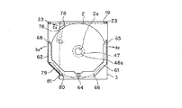
筐体3の前面には、図2に示すように、略矩形平板状のフロントパネル18が取り付けられている。このフロントパネル18には、光ディスク2がディスクの面方向に出し入れされるディスク挿脱口19が設けられている。すなわち、光ディスク2は、このディスク挿脱口19から筐体3の内部へと挿入したり、或いはこのディスク挿脱口19から筐体3の外部へと排出したりすることが可能となっている。また、図5に示すように、フロントパネル18の前面には、光ディスク2に対するアクセス状態を点灯表示する表示部20や、光ディスク2を排出する際に押圧されるイジェクトボタン21が設けられている。
A
なお、ディスク挿脱口19は、光ディスク2を中央部分に導くために、この中央部分の厚み方向の寸法が最も大きく両端部に向かうに従って厚み方向の寸法が僅かに小さくなる形状を有している。また、ディスク挿脱口19の上下面には、フロントパネル18の前面側から筐体3の内側に向かって互いに近接する方向に傾斜した傾斜面38が設けられている。この傾斜面38は、ディスク挿入時に光ディスク2をディスク挿脱口19に誘い込むためのものである。
The disk insertion /
ディスク挿脱口19は、フロントパネル18の長手方向に沿って、光ディスク2の径よりもやや長い長さと、光ディスク2の厚さよりもやや長い高さの矩形開口からなる。また、ディスク挿脱口19は、図5及び図6に示すように、長手方向の両端部19a,19bに、筐体3より挿脱される光ディスク2の外周と摺接される摺接片23が設けられている。摺接片23は、例えば黒色の人工皮革スエード(ポリエステル繊維にポリウレタン樹脂が含浸された材料)が用いられ、図7に示すように、フロントパネル18の背面側に形成された収納凹部24に接着剤等を介して取り付けられている。
The disc insertion /
そして摺接片23は、図2に示すように、光ディスク2がディスク挿脱口19より挿入又はディスク挿脱口19より排出されると、光ディスク2が半分程度、筐体3の外方へ臨まされた位置にあるとき、光ディスク2の挿脱方向と直交する方向の外周部2Aと摺接する。これにより摺接片23は、光ディスク2の当該外周部2Aに対して相対的に摺動するため、光ディスク2の挿入力又は排出力に対して負荷を与え、挿入力又は排出力を抑えることができる。
As shown in FIG. 2, when the
光ディスク2が筐体3内に挿入されるときには、筐体3内に半分程度挿入された時に一瞬だけ負荷が掛かるものの、ユーザによって引き続き光ディスク2の挿入が続けられ、後述するディスク搬送機構60に引き渡されて、このディスク搬送機構60によって筐体3のディスク装着部に装着される。一方、光ディスク2が筐体3外へ排出されるときには、ディスク搬送機構60による光ディスクの排出力に対して負荷が掛かり、光ディスク2の排出量が最適化される。すなわち、摺接片23は、光ディスク2が半分程度排出されたときに光ディスク2の外周部2Aに摺接して負荷を与えることから、光ディスク2の中心孔2aがディスク挿脱口19より外部に臨まされたときに光ディスク2の排出が停止することができる。これにより、ユーザはディスク挿脱口19より外部に臨まされた光ディスク2の中心孔2aの内周と光ディスク2の外周部を把持し、容易に光ディスク2の抜き出しを行うことができる。
When the
また、後述するようにディスク搬送機構60が捻りコイルバネ70によって第1、第2の回動アーム61,62を回動させることにより、厚さや重さの異なる各種光ディスク2を筐体3外へ排出させるときにも、摺接片23は、光ディスク2がディスク挿脱口19より半分程度排出されたときの排出方向と直交する方向の外周部2Aと摺接することにより、光ディスク2の種類に応じた排出力のバラツキを解消し、各光ディスク2にとって最適な排出位置に停止させることができる。
Further, as will be described later, when the
また、ディスク挿脱口19から排出された光ディスク2は、その中心孔2aがディスク挿脱口19から筐体3の外部に露出する位置において摺接片23との摩擦により保持されるため、自重によりディスク挿脱口19から脱落するのを防ぐことができる。
The
なお、上述した摺接片は、ディスク挿脱口の長手方向の両端部に設けるほか、ディスク挿脱口の長手方向の何れか一方の端部に設けるようにしてもよい。 The sliding contact pieces described above may be provided at both ends in the longitudinal direction of the disk insertion / removal opening, or at any one end in the longitudinal direction of the disk insertion / removal opening.
なお、図6に示すフロントパネル18の背面側には、このフロントパネル18を筐体3の前面に取り付けるための複数の係止片が設けられている。
A plurality of locking pieces for attaching the
次いで、光ディスク2をチャッキングし回転駆動するとともに、情報信号の記録及び/又は再生を行うベースユニット40について説明する。
Next, the
ベースユニット40は、図8に示すように、ボトムケース4の底面部に備えられ、ディスク挿脱口19から筐体3の内部に挿入された光ディスク2が装着されるディスク装着部41と、このディスク装着部41に装着された光ディスク2を回転駆動するディスク回転駆動機構42と、このディスク回転駆動機構42により回転駆動される光ディスク2に対して信号の書き込み又は読み出しを行う光ピックアップ43と、この光ピックアップ43を光ディスク2の半径方向に送り動作させるピックアップ送り機構44とを有し、これらがベース45に一体に設けられた超薄型構造を有している。
As shown in FIG. 8 , the
図4に示すように、このベースユニット40は、ボトムケース4の底面部においてディスク装着部41が略々中央に位置するよう、シャーシ11よりも前面側に配置されている。また、このベースユニット40は、後述するベース昇降機構90によって昇降可能とされており、光ディスク2が挿入される前の初期状態において、ディスク挿脱口19から筐体3の内部に挿入される光ディスク2の搬送領域よりも下方に位置している。そして、ベースユニット40は、光ディスク2が挿入されると、ベース昇降機構90によって上昇され、光ディスク2をディスク装着部41に装着し、回転駆動することによって光ピックアップ43が情報信号の記録及び/又は再生を行う。次いで、光ディスク2を排出する際には、ベースユニット40は、ベース昇降機構90によって下降されることによりディスク装着部41から光ディスク2が外れ、後述するディスク搬送機構60によって搬送可能とする。
As shown in FIG. 4, the
ベース45は、板金を所定の形状に打ち抜き、その周囲を僅かに下方に折り曲げて形成されている。ベース45の主面には、後述するディスク装着部41のターンテーブル47を上方へと臨ませる略半円状のテーブル用開口部45aと、後述する光ピックアップ43の対物レンズ51を上方へと臨ませる略矩形状のピックアップ用開口部45bとが連続形成されている。なお、ベース45の上面部には、これら開口部45a,45bに対応した開口部が形成された化粧板(図示せず。)が取り付けられる。
The
ディスク装着部41は、ディスク回転駆動機構42により回転駆動されるターンテーブル47を有し、このターンテーブル47の中心部には、光ディスク2を装着するためのチャッキング機構48が設けられている。このチャッキング機構48は、光ディスク2の中心孔2aに係合される係合突部48aと、この係合突部48aに係合された光ディスク2の中心孔2aの周囲を係止する複数の係止爪48bとを有し、光ディスク2をターンテーブル47上に保持する。
The
ディスク回転駆動機構42は、光ディスク2をターンテーブル47と一体に回転駆動する扁平状のスピンドルモータ49を有し、このスピンドルモータ49は、上面部に設けられたターンテーブル47がベース45のテーブル用開口部45aから僅かに突出するように、支持板50を介してベース45の下面にネジ止めにより取り付けられている。
The disk
光ピックアップ43は、光源となる半導体レーザから出射された光ビームを対物レンズ51により集光させて光ディスク2の信号記録面に照射し、この光ディスク2の信号記録面で反射された戻りの光ビームを受光素子等からなる光検出器により検出する光学ブロックを有し、光ディスク2に対する信号の書き込み又は読み出しを行うものである。
The
この光ピックアップ43は、対物レンズ51を光軸方向(フォーカッシング方向という。)と、光ディスクの記録トラックと直交する方向(トラッキング方向という。)とに変位駆動する2軸アクチュエータ等の対物レンズ駆動機構を有し、上述した光検出器により検出された光ディスク2からの検出信号に基づいて、この2軸アクチュエータにより対物レンズ51をフォーカッシング方向及びトラッキング方向に変位させながら、光ディスク2の信号記録面上に対物レンズ51の焦点を合わせるフォーカスサーボや、対物レンズ51により集光される光ビームのスポットを記録トラックに追従させるトラッキングサーボ等の駆動制御を行うようになされている。なお、対物レンズ駆動機構としては、このようなフォーカシング制御及びトラッキング制御に加えて、対物レンズ51により集光された光ビームを光ディスク2の信号記録面に垂直に照射させるように、光ディスク2の信号記録面に対する対物レンズ51の傾き(スキュー)を調整可能とする3軸アクチュエータを用いてもよい。
This
ピックアップ送り機構44は、光ピックアップ43が搭載されたピックアップベース53と、このピックアップベース53を光ディスク2の半径方向にスライド可能に支持する一対のガイド軸54a,54bと、これら一対のガイド軸54a,54bに支持されたピックアップベース53を光ディスク2の半径方向に変位駆動する変位駆動機構55とを有している。
The
ピックアップベース53には、一対のガイド軸54a,54bのうち、一方のガイド軸54aを挿通するガイド孔が形成された一対のガイド片56a,56bと、他方のガイド軸54bを挟み込むガイド溝が形成されたガイド片57とが互いに対向する側面から突出形成されている。これにより、ピックアップベース53は、一対のガイド軸54a,54bにスライド可能に支持されている。
The
一対のガイド軸54a,54bは、ベース45の下面に光ディスク2の半径方向と互いに平行となるように配置されており、ベース45のピックアップ用開口部45bから光ピックアップ43が臨むピックアップベース53を光ディスク2の内外周に亘って案内する。
The pair of
変位駆動機構55は、ベース45に取り付けられた駆動モータ58の回転駆動をギヤやラック(図示せず。)を介して直線駆動に変換し、ピックアップベース53を一対のガイド軸54a,54bに沿った方向、すなわち光ディスク2の半径方向に変位駆動させる。
The
このディスクドライブ装置1は、図4に示すように、ディスク挿脱口19から光ディスク2が挿脱されるディスク挿脱位置と、ディスク装着部41のターンテーブル47に光ディスク2が装着されるディスク装着位置との間で光ディスク2の搬送を行うディスク搬送機構60を備えている。このディスク搬送機構60は、天板部5aのディスク装着部41と対向する主面と、ディスク挿脱口19から挿入された光ディスク2の主面との間で移動操作されるサポート部材として、当該光ディスク2の主面と平行な面内で揺動可能とされた第1の回動アーム61及び第2の回動アーム62を有している。
As shown in FIG. 4, the disk drive device 1 includes a disk insertion / removal position where the
これら第1の回動アーム61及び第2の回動アーム62は、ディスク装着部41を挟んだ左右の両側に各々配置されており、それぞれディスク装着部41よりも背面側に位置する基端部が回動可能に支持されると共に、ディスク装着部41よりも前面側に位置する先端部がディスク挿脱口19から挿入された光ディスク2の主面と平行な面内で互いに近接又は離間する方向に揺動可能となっている。
The first
具体的に、第1の回動アーム61は、長尺状の板金からなり、ディスク装着部41のターンテーブル47を挟んだ左右の一方側(例えば図4中の右側)に位置して、基端部がシャーシ11上に設けられた第1の支軸64を介して、図4中矢印a1方向及び矢印a2方向に回動可能に支持されている。また、第1の回動アーム61の先端部には、ディスク挿脱口19から挿入された光ディスク2の外周部と当接される第1の前面側当接部材65が下方に向かって突出して設けられている。また、第1の回動アーム61の基端部近傍には、光ディスク2をディスク装着位置に位置決めする際に、第1の前面側当接部材65と共に光ディスク2の外周部に当接される第1の背面側当接部材66が下方に向かって突出して設けられている。
Specifically, the first
第1の前面側当接部材65及び第1の背面側当接部材66は、光ディスク2よりも柔らかい樹脂からなり、ディスク挿脱口19から挿入された光ディスク2の外周部と当接される中央部分が内側に湾曲し、その両端部が拡径されたフランジ部65a,66aとして光ディスク2の高さ方向の移動を規制する略鼓形形状を有している。また、これら第1の前面側当接部材65及び第1の背面側当接部材66は、第1の回動アーム61のディスク装着部41と対向する主面に回転可能に取り付けられた小径の回転ローラであってもよい。
The first front-
一方、第2の回動アーム62は、長尺状の板金からなり、ディスク装着部41のターンテーブル47を挟んだ左右の他方側(例えば図4中の左側)に位置して、基端部がシャーシ11上に設けられた上記第1の支軸64を介して、図4中矢印b1方向及び矢印b2方向に回動可能に支持されている。また、第2の回動アーム62の先端部には、ディスク挿脱口19から挿入された光ディスク2の外周部に当接される第2の前面側当接部材68が下方に向かって突出して設けられている。
On the other hand, the second
第2の前面側当接部材68は、光ディスク2よりも柔らかい樹脂からなり、ディスク挿脱口19から挿入された光ディスク2の外周部と当接される中央部分が内側に湾曲し、その両端部が拡径されたフランジ部68aとして光ディスク2の高さ方向の移動を規制する略鼓形形状を有している。また、この第2の前面側当接部材68は、第2の回動アーム62のディスク装着部41と対向する主面に回転可能に取り付けられた小径の回転ローラであってもよい。
The second front-
また、第1の回動アーム61及び第2の回動アーム62の基端部には、これら回動アーム61,62を互いに近接する方向に付勢する付勢手段である捻りコイルバネ70が設けられている。捻りコイルバネ70は、その巻回部分に第1の支軸64が挿通された状態で、一端部が第1の回動アーム61の基端部に係止され、他端部が第2の回動アーム62の基端部に係止されることによって、第1、第2の回動アーム61,62を互いに近接する方向に付勢している。また捻りコイルバネ70は、第1、第2の回動アーム61,62を回動させて、厚みや重さの異なる複数種類の光ディスク2をいずれも筐体3内に引き込み、また筐体3外へ排出させるに十分な付勢力を備えている。
Further, a torsion coil spring 70 is provided at the base end portion of the first
このように、第1の回動アーム61と第2の回動アーム62とは、ディスク装着部41のターンテーブル47を挟んで略対称となる位置に配置されており、互いの回動中心がディスク装着部47よりも背面側の略中央部において一致している。また、第1の回動アーム61の先端部及び第2の回動アーム62の先端部は、上述した天板部5aのガイド溝9に係合された状態で回動方向に沿ってスライド可能に支持されている。
As described above, the
ディスク搬送機構60は、これら第1の回動アーム61と第2の回動アーム62とを連動させるための連動機構71を有しており、この連動機構71を介して第1の回動アーム61と第2の回動アーム62とが互いに逆向きに回動可能となっている。具体的に、この連動機構71は、第1の回動アーム61と第2の回動アーム62とを連結する第1の連結アーム72及び第2の連結アーム73を有している。これら第1の連結アーム72及び第2の連結アーム73は、長尺状の板金からなり、それぞれの長手方向の一端部が第1の回動アーム61の基端部と第2の回動アーム62の基端部とに回動可能に支持され、それぞれの長手方向の他端部が第2の支軸74を介して回動可能に支持された、いわゆるパンタグラフ構造を有している。また、第2の支軸74は、シャーシ11の第1の支軸64よりも前面側に設けられたガイドスリット75に係合されており、このガイドスリット75は、光ディスク2の挿入方向に亘って直線状に形成されている。
The
したがって、第1の回動アーム61と第2の回動アーム62とは、第2の支軸74がガイドスリット75内をスライドすることで、第1の連結アーム72及び第2の連結アーム73を介して互いに逆向きに回動可能となっている。すなわち、第1の回動アーム61の先端部と第2の回動アーム62の先端部とは、このような連動機構71によって、互いに近接又は離間する方向に揺動可能となっている。
Accordingly, the first
また、ディスク搬送機構60は、光ディスク2をディスク挿脱口19から筐体3の内部へと引き込むローディング動作を補助するためのローディング補助手段として、ディスク挿脱口19から挿入される光ディスク2の主面と平行な面内で揺動可能とされた第3の回動アーム76を有している。第3の回動アーム76は、長尺状の板金からなり、ディスク装着部41のターンテーブル47を挟んだ左右の一方側(例えば図4中左側)の第2の回動アーム62よりも前面側に位置して、基端部がデッキ部4a上に設けられた支軸77を介して、矢印c1方向及び矢印c2方向に回動可能に支持されている。また、第3の回動アーム76の先端部には、ディスク挿脱口19から挿入された光ディスク2の外周部に当接される第3の当接部材78が上方に向かって突出して設けられている。
Further, the
第3の当接部材78は、第3の回動アーム76の天板部5aと対向する主面に回転可能に取り付けられた小径の回転ローラであり、光ディスク2よりも柔らかい樹脂からなる。また、この第3の当接部材78は、ディスク挿脱口19から挿入された光ディスク2の外周部と当接される中央部分が内側に湾曲し、その両端部が拡径されたフランジ部78aとして光ディスク2の高さ方向の移動を規制する略鼓形形状を有している。
The third abutting
かかる第3の回動アーム76は、図示しない捩りコイルバネが係止されることにより、第3の当接部材78が光ディスク2の外周部に当接される方向と、光ディスク2の外周部から離間する方向とに切り換え可能に付勢される。
The third
また、ディスク搬送機構60は、光ディスク2をディスク挿脱口19から筐体3の外部へと排出するイジェクト動作を補助するためのイジェクト補助手段として、ディスク挿脱口19から挿入される光ディスク2の主面と平行な面内で揺動可能とされた第4の回動アーム79を有している。第4の回動アーム79は、長尺状の板金からなり、ディスク装着部41のターンテーブル47を挟んだ左右の一方側(例えば図4中左側)の第2の回動アーム62の中間部において、矢印d1方向及び矢印d2方向に回動可能に支持されている。また、第4の回動アーム79の先端部には、ディスク挿脱口19から挿入された光ディスク2の外周部の背面側に当接される第4の当接部材80が上方に向かって突出して設けられている。
The
この第4の当接部材80は、光ディスク2よりも柔らかい樹脂からなり、ディスク挿脱口19から挿入された光ディスク2の外周部と当接される中央部分が内側に湾曲し、その両端部が拡径されたフランジ部80aとして光ディスク2の高さ方向の移動を規制する略鼓形形状を有している。また、この第4の当接部材80は、第4の回動アーム79の天板部5aと対向する主面に回転可能に取り付けられた小径の回転ローラであってもよい。
The fourth abutting
また、第2の回動アーム62には、この第4の回動アーム79が背面側、すなわち矢印d1方向に回動された際に、当該第4の回動アーム79の背面側への回動を規制する規制片81が設けられている。
Further, when the fourth
このディスク搬送機構60は、上述した各回動アーム61,62,76,79を協働させるための駆動レバー82を有している。この駆動レバー82は、全体が略直方体状に形成された樹脂部材からなり、ボトムケース4の底面部において、このボトムケース4の一方の側面部とベースユニット40との間に配置されている。また、この駆動レバー82は、ディスク挿脱口19から筐体3の内部に挿入される光ディスク2よりも下方に位置しており、その上面部がデッキ部4aの底面部と略一致した高さを有している。そして、この駆動レバー82は、ボトムケース4の底面部に設けられた駆動モータやギヤ群等からなる図示を省略する変位駆動機構を介して前後方向にスライド駆動される。
The
そして、ディスク搬送機構60では、この駆動レバー82のスライド動作に連動して、上述した第2の支軸74がガイドスリット75内をスライドすることになる。これにより、第1の回動アーム61及び第2の回動アーム62は、連動機構71を介して互いに逆向きに回動操作される。また、第3の回動アーム76の基端側には、駆動レバー82の上面に設けられたガイドスリット83に係合されるガイドピン84が設けられている。これにより、第3の回動アーム76は、駆動レバー82のスライド動作に連動して、ガイドピン84がガイドスリット83内をスライドすることで回動操作される。また、第4の回動アーム79も、図示を省略する連結機構を介して駆動レバー82のスライド動作に連動して回動操作される。
In the
そして、このディスク搬送機構60では、これら第1の回動アーム61、第2の回動アーム62、第3の回動アーム76及び第4の回動アーム79が互いに協働しながら、光ディスク2をディスク挿脱口から筐体3の内部へと引き込むローディング動作と、光ディスク2をディスク装着位置に位置決めするセンタリング動作と、光ディスク2をディスク挿脱口19から筐体3の外部へと排出するイジェクト動作とを行う。
In the
このディスクドライブ装置1は、図4に示すように、上述した駆動レバー82のスライドに連動して、光ピックアップ43を支持するベース45を昇降操作するベース昇降機構90を備えている。
As shown in FIG. 4, the disk drive apparatus 1 includes a
このベース昇降機構90は、ベース45を上昇させて、ディスク搬送機構60によってディスク装着位置に位置決めされた光ディスク2をディスク装着部41のターンテーブル47に装着するチャッキング位置と、ベース45を下降させて、ディスク装着部41のターンテーブル47から光ディスク2を離脱するチャッキング解除位置と、ベース45をチャッキング位置とチャッキング解除位置との間に位置させて、光ディスク2に対する信号の記録又は再生を行う中間位置との間でベース45を昇降操作する。
The
具体的に、上述した駆動レバー82のベース45と対向する側面には、上記チャッキング位置、上記チャッキング解除位置及び上記中間位置に対応したカムスリット(図示せず。)が長手方向に亘って形成されている。
Specifically, a cam slit (not shown) corresponding to the chucking position, the chucking release position, and the intermediate position extends in the longitudinal direction on the side surface of the drive lever 82 facing the
また、ボトムケース4の底面部には、ベース45の背面側の側面に沿ってカムレバー91が配置されている。このカムレバー91は、長尺状の平板部材からなり、駆動レバー82の前後方向のスライドに連動して、当該駆動レバー82のスライド方向と略直交する方向にスライド操作される。また、このカムレバー91の中間部には、ベース45と対向する端縁部から上方に向かって折り曲げられたカム片92が設けられている。このカム片92には、上記チャッキング位置、上記チャッキング解除位置及び上記中間位置に対応したカムスリット(図示せず。)が長手方向に亘って形成されている。
A
また、ボトムケース4の底面部には、折曲げ片93がベース45の背面側の側面に沿って折り曲げ形成されている。この折曲げ片93には、ベース45を昇降させるための鉛直スリット(図示せず。)が上下方向に亘って形成されている。
A
これに対して、ベース45は、図8に示すように、駆動レバー82と対向する側面のディスク装着部41側に位置して、駆動レバー82のカムスリットに係合されて支持される第1の支軸95と、カムレバー91と対向する側面のディスク装着部41側に位置して、カム片92のカムスリット及び折曲げ片93の鉛直スリットに係合されて支持される第2の支軸96と、駆動レバー82と対向する側面とは反対側の側面の前面側に位置して、ボトムケース4の他方側の側面に設けられた軸孔97に回動可能に支持された第3の支軸98と、カムレバー91と対向する側面とは反対側の側面の前面側に位置して、ゴム等の粘弾性部材からなるインシュレータ99を介してボトムケース4の底面部にネジ100により固定支持された固定支持部101とを有している。
On the other hand, as shown in FIG. 8 , the
したがって、このベース昇降機構90では、駆動レバー82及びカムレバー91のスライドに連動して、第1の支軸95が駆動レバー82のカムスリット内をスライドすると共に、第2の支軸96がカムレバー91のカムスリット及び折曲げ片93の鉛直スリット内をスライドすることによって、ベース45のディスク装着部41側が前面側に対して、上記チャッキング位置と上記チャッキング解除位置と上記中間位置との間で昇降操作される。
Therefore, in the
また、ボトムケース4の底面部には、図4に示すように、このベース昇降機構90がベース45を下降させたとき、ディスク装着部41のターンテーブル47上に装着された光ディスク2をターンテーブル47から離脱させるためのチャッキング解除手段である押上ピン102が設けられている。この押上ピン102は、ベースユニット40のディスク装着部41近傍、具体的にはディスク装着部41に最も近接したベース45の背面側に位置して、ボトムケース4の底面部から上方に向かって突出して設けられている。
As shown in FIG. 4, when the
次に、以上のように構成されるディスクドライブ装置1の具体的な動作について説明する。このディスクドライブ装置1では、図9に示すように、光ディスク2が挿入される前の初期状態において、第1の回動アーム61及び第2の回動アーム62は、それぞれの先端部が所定の広がり角で開いた状態で保持されている。また、第3の回動アーム76は、先端部が基端部よりも外側に位置し且つ先端部が基端部よりも前面側に位置した状態で保持されている。また、第4の回動アーム79は、先端部が基端部よりも内側に位置し且つ先端部が基端部よりも前面側に位置した状態で保持されている。また、駆動レバー82はボトムケース4の前面側に位置している。
Next, a specific operation of the disk drive device 1 configured as described above will be described. In the disk drive device 1, as shown in FIG. 9 , in the initial state before the
このディスクドライブ装置1は、筐体3のディスク挿脱口19から厚さや重さの異なる光ディスク2が挿入された場合であっても、これら光ディスク2をディスク装着位置まで引き込むローディング動作を行う。具体的に、筐体3のディスク挿脱口19から光ディスク2が挿入された場合には、先ず、図10に示すように、ディスク挿脱口19から筐体3の内部に挿入された光ディスク2の外周部の背面側が第1の回動アーム61の第1の前面側当接部材65及び第2の回動アーム62の第2の前面側当接部材68に当接された状態となる。
The disk drive device 1 performs a loading operation to pull the
なお、光ディスク2が筐体3内に挿入されるときには、筐体3内に半分程度挿入された時にディスク挿脱口19の両端部19a,19bに設けられた摺接片23が光ディスク2の外周部2Aに摺接する一瞬だけ負荷が掛かるものの、ユーザによって引き続き光ディスク2の挿入が続けられ、ディスク搬送機構60に引き渡される。
When the
次に、図11に示すように、この状態から更に光ディスク2がディスク挿脱口19から筐体3の内部に押し込まれると、第1の回動アーム61と第2の回動アーム62とが第1の前面側当接部材65と第2の前面側当接部材68との間で光ディスク2の外周部を挟み込む。このとき、第1の前面側当接部材65と第2の前面側当接部材68とが光ディスク2の外周部の背面側に当接された状態で、第1の回動アーム61と第2の回動アーム62とが捻りコイルバネの付勢に抗して互いに離間する方向、すなわち図11中に示す矢印a2,b2の方向に回動される。
Next, as shown in FIG. 11, when the
そして、第1の回動アーム61及び第2の回動アーム62が互いに離間する方向に所定量だけ回動されたとき、回路基板に設けられた検出スイッチが押圧されることによって、変位駆動機構による駆動レバー82の背面側へのスライドが開始される。これにより、第3の回動アーム76は、図11中に示す矢印c1の方向に回動される。また、第3の回動アーム76は、第3の当接部材78が光ディスク2の外周部の前面側に当接された状態となることで、この光ディスク2の外周部の前面側を押圧しながら、光ディスク2を筐体3の内部へと引き込むことになる。
Then, when the first
そして、図12に示すように、光ディスク2の中心孔2aが第1の前面側当接部材65と第2の前面側当接部材68とを結ぶ直線よりも背面側に位置するまで、光ディスク2が筐体3の内部に引き込まれると、第1の前面側当接部材65と第2の前面側当接部材68とが光ディスク2の外周部に沿って背面側から前面側へと回り込む。すると、今度は第1の前面側当接部材65と第2の前面側当接部材68とが光ディスク2の外周部の前面側に当接された状態で、第1の回動アーム61と第2の回動アーム62とが捻りコイルバネ70に付勢されて互いに近接する方向、すなわち図12中に示す矢印a1,b1の方向に回動される。これにより、第1の回動アーム61及び第2の回動アーム62は、光ディスク2の外周部の前面側を押圧しながら、光ディスク2を図13に示すディスク装着位置まで引き込むことになる。
Then, as shown in FIG. 12 , the
また、第4の回動アーム79は、第4の当接部材80が光ディスク2の外周部の背面側に当接された状態で押圧されることによって、図12中に示す矢印d1の方向に回動される。そして、第4の回動アーム79は、光ディスク2が図13に示すディスク装着位置で引き込まれた際に、第2の回動アーム62の規制片81に当接され、その回動が規制された状態となる。
Further, the fourth
このディスクドライブ装置1では、図13に示すように、第1の回動アーム61及び第2の回動アーム62が、これら厚みや重さの異なる各種光ディスク2をディスク装着位置まで引き込んだ際に、第1の前面側当接部材65、第1の背面側当接部材66、第2の前面側当接部材68、第4の当接部材80の内側に光ディスク2を挟み込むことによって、これら光ディスク2をディスク装着位置に位置決めするセンタリング動作を行う。すなわち、光ディスク2の中心孔2aと、ターンテーブル47の係合突部48aとを当該光ディスク2の主面と直交する方向において一致させる。
In this disk drive device 1, as shown in FIG. 13 , when the first
次に、このディスクドライブ装置1では、上述した光ディスク2のセンタリング動作の後に、ベース昇降機構90がベース45を上昇させることによって、ディスク装着位置に位置決めされた光ディスク2をディスク装着部41のターンテーブル47に装着するチャッキング動作を行う。
Next, in the disk drive device 1, after the above-described centering operation of the
具体的には、図14に示すチャッキング解除位置からベース昇降機構90によりベース45が図15に示すチャッキング位置まで上昇すると、ディスク装着位置に位置決めされた光ディスク2の中心孔2aに係合突部48aが入り込みながら、天板部5aの当接突部7に光ディスク2の中心孔2aの周囲が押し付けられることによって、係合突部48aが光ディスク2の中心孔2aに係合されると共に、複数の係止爪48bが光ディスク2の中心孔2aの周囲を係止した状態で、光ディスク2がターンテーブル47上に保持される。そして、光ディスク2がターンテーブル47上に保持された状態で、ベース昇降機構90によりベース45が図16に示す中間位置まで下降する。
Specifically, when the
また、このディスクドライブ装置1では、上述したチャッキング動作の後に、図17に示すように、駆動レバー82の背面側へのスライドに連動して、第1の回動アーム61及び第2の回動アーム62が互いに離間する方向、すなわち図17中に示す矢印a2,b2の方向に僅かに回動される。このとき、第4の回動アーム79は、規制片81に当接されたまま、第2の回動アーム62と一体に回動されることになる。また、第3の回動アーム76は、駆動レバー82の背面側へのスライドに連動して、図17中に示す矢印c2の方向に僅かに回動される。これにより、ターンテーブル47に保持された光ディスク2の外周部からは、第1の前面側当接部材65、第1の背面側当接部材66、第2の前面側当接部材68、第3の当接部材78、第4の当接部材80が離間した状態となる。
Further, in the disk drive device 1, after the above-described chucking operation, as shown in FIG. 17 , the first
このディスクドライブ装置1では、図16及び図17に示す状態から、上記パーソナルコンピュータ1000から記録又は再生の指令が送られると、この指令に基づいて、光ディスク2に対して情報信号の記録又は再生が行われる。具体的には、スピンドルモータ49が光ディスク2をターンテーブル47と一体に回転駆動すると共に、ピックアップ送り機構44によって光ピックアップ43が外周側から内周側へ移動し、フォーカスサーボ制御とトラッキングサーボ制御がかかると、この光ディスク2のリードイン領域に記録されているTOCデータの読み出しを行う。この後、情報信号を記録する場合にあっては、読み出したTOCデータに基づいて、光ディスク2のプログラム領域内の所定のアドレスに、光ピックアップ43が移動する。また、情報信号の再生時にあっては、指定されたデータが記録されたプログラム領域内のアドレスに、光ピックアップ43が移動する。そして、この光ピックアップ43が光ディスク2の所望の記録トラックに対して情報信号の書き込み又は読み出し動作を行う。
In this disk drive device 1, when a recording or reproduction command is sent from the
このディスクドライブ装置1では、フロントパネル18に設けられたイジェクトボタン21が押圧される、或いは上記パーソナルコンピュータ1000からディスクドライブ装置1に対してイジェクトの指令が送られると、この指令に基づいて、先ず、変位駆動機構による駆動レバー82の前面側へのスライドが開始される。
In the disk drive device 1, when an
そして、図18に示すように、この駆動レバー82の前面側へのスライドに連動して、第1の回動アーム61及び第2の回動アーム62が互いに近接する方向、すなわち図18中に示す矢印a1,b1の方向に僅かに回動される。このとき、第4の回動アーム79は、規制片81に当接されたまま、第2の回動アーム62と一体に回動されることになる。また、第3の回動アーム76は、駆動レバー82の前面側へのスライドに連動して、図18中に示す矢印c1の方向に僅かに回動される。
Then, as shown in FIG. 18 , in conjunction with the slide of the drive lever 82 to the front side, the first
これにより、ターンテーブル47に保持された光ディスク2の外周部に、第1の前面側当接部材65、第1の背面側当接部材66、第2の前面側当接部材68、第3の当接部材78、第4の当接部材80が当接された状態となる。
As a result, the first front-
次に、このディスクドライブ装置1では、ベース昇降機構90がベース45を上記チャッキング解除位置まで下降させることによって、ディスク装着部41のターンテーブル47から光ディスク2を離脱するチャッキング解除動作を行う。具体的には、ベース45が上記チャッキング解除位置まで下降すると、押上ピン102の先端部がディスク装着部41のターンテーブル47に装着された光ディスク2の内周側の非信号記録領域に当接することによって、この光ディスク2を押し上げながら、光ディスク2の中心孔2aと係合突部48aの係止爪48bとの係合を解除し、ターンテーブル47上から離脱させる。
Next, in the disk drive device 1, the
次に、このディスクドライブ装置1では、ディスク装着部41にある光ディスク2をディスク挿脱口19から筐体3の外部へと排出するイジェクト動作を行う。具体的に、筐体3のディスク挿脱口19から大径ディスク2Aを排出する場合には、先ず、図19に示すように、駆動レバー82の前面側へのスライドに連動して、第4の回動アーム79が図19中に示す矢印d2の方向に回動される。また、第4の回動アーム79は、第4の当接部材80が光ディスク2の外周部の背面側に当接された状態となることで、この光ディスク2の外周部の背面側を押圧しながら、光ディスク2を筐体3の外部へと押し出すことになる。
Next, in the disk drive device 1, an ejecting operation for ejecting the
そして、図20に示すように、光ディスク2の中心孔2aが第1の前面側当接部材65と第2の前面側当接部材68とを結ぶ直線よりも前面側に位置するまで、光ディスク2が筐体3の外部へと排出されると、第1の前面側当接部材65と第2の前面側当接部材68とが光ディスク2の外周部に沿って前面側から背面側へと回り込む。すると、今度は第1の前面側当接部材65と第2の前面側当接部材68とが光ディスク2の外周部の背面側に当接された状態で、第1の回動アーム61と第2の回動アーム62とが捻りコイルバネ70に付勢されて互いに近接する方向、すなわち図20中に示す矢印a1,b1の方向に回動される。これにより、第1の回動アーム61及び第2の回動アーム62は、光ディスク2の外周部の背面側を押圧しながら、光ディスク2を図21に示すディスク挿脱位置、すなわち光ディスク2の中心孔2aがディスク挿脱口19から筐体3の外部に露出する位置まで押し出すことになる。
As shown in FIG. 20 , the
光ディスク2が図21に示すディスク挿脱位置へ押し出されると、ディスク挿脱口19の両端部19a,19bに設けられた摺接片23は、ディスク搬送機構60の第1、第2の回動アーム61,62によって押し出される光ディスクに対して負荷を掛けることにより、光ディスク2の排出量を最適化する。すなわち、摺接片23は、光ディスク2が半分程度排出されたときに光ディスク2の外周部2Aに摺接して負荷を与えることから、図21に示す光ディスク2の中心孔2aがディスク挿脱口19より外部に臨まされたディスク排出位置に光ディスク2を停止することができる。これにより、ユーザはディスク挿脱口19より外部に臨まされた光ディスク2の中心孔2aの内周と光ディスク2の外周部を把持し、容易に光ディスク2の抜き出しを行うことができる。
When the
ここで、上述したように、第1及び第2の回動アーム61,62は、捻りコイルバネ70の付勢力によって互いに近接する方向へ回動付勢されることにより光ディスク2を筐体3外へ押し出すものである。したがって、光ディスクの種類によっては、ディスクの厚みや重さにバラツキが生じるため、捻りコイルバネ70による付勢力だけでは複数種類の光ディスク2のうち、いずれの光ディスク2が用いられた場合にも一定のディスク排出位置に光ディスク2を排出することは難しい。しかし、本発明が適用されたディスクドライブ装置1は、ディスク挿脱口19の両端部に摺接片23を設けているため、光ディスク2がディスク挿脱口19より半分程度排出されるまでは捻りコイルバネ70による付勢力を受けた第1及び第2の回動アーム61,62によって光ディスク2を押し出し、光ディスク2がディスク挿脱口19より半分程度排出されると、このタイミングで摺接片23が光ディスク2の外周部2Aに摺接して負荷を掛ける。これにより、厚みや重さの異なる各種光ディスク2が用いられた場合にも、何れの光ディスク2であっても図21に示すディスク挿脱位置、すなわち光ディスク2の中心孔2aがディスク挿脱口19から筐体3の外部に露出する位置にて光ディスク2の排出を停止させることができる。
Here, as described above, the first and second
なお、第3の回動アーム76は、第3の当接部材78が光ディスク2の外周部に当接された状態で押圧されることによって、図20中に示す矢印c2の方向に回動される。
The third
本発明は、上述したノート型パーソナルコンピュータ1000に搭載されるスロットイン型のディスクドライブ装置1に適用したものに限定されるものではなく、光ディスクに対して情報信号の記録及び/又は再生を行う、家庭用、車載用のディスクドライブ装置やゲーム機等に対して広く適用可能である。
The present invention is not limited to the one applied to the slot-in type disk drive device 1 mounted on the above-described notebook type
1 ディスクドライブ装置、2 光ディスク、3 筐体、18 フロントパネル、19 ディスク挿脱口、23 摺接片、24 収納凹部、40 ベースユニット、41 ディスク装着部、42 ディスク回転駆動機構、43 光ピックアップ、44 ピックアップ送り機構、45 ベース、47 ターンテーブル、48 チャッキング機構、48a 係合突部、48b 係止爪、61,62 第1,第2の回動アーム、64 第1の支軸、70 捻りコイルバネ、71 連結機構、90 ベース昇降機構
DESCRIPTION OF SYMBOLS 1 Disk drive apparatus, 2 Optical disk, 3 Housing | casing, 18 Front panel, 19 Disk insertion / extraction slot, 23 Sliding contact piece, 24 Storage recessed part, 40 Base unit, 41 Disk mounting part, 42 Disk rotation drive mechanism, 43 Optical pick-up, 44 Pickup feed mechanism, 45 base, 47 turntable, 48 chucking mechanism, 48a engagement protrusion, 48b locking claw, 61, 62 first and second rotating arms, 64 first support shaft, 70
Claims (3)
光ディスクの外周を挟持する複数の回動アームと、上記複数の回動アームを上記光ディスクの搬送位置に応じて所定方向に付勢する付勢手段とを備え、上記前面パネルのディスク挿脱口から上記光ディスクが挿脱されるディスク挿脱位置と、上記筐体内に挿入された光ディスクが装着されるディスク装着位置との間で、上記光ディスクの搬送を行うディスク搬送機構と、
上記筐体内に搬送された光ディスクが装着されるディスク装着部と、該ディスク装着部に装着された光ディスクを回転駆動するディスク回転駆動機構と、該ディスク回転駆動機構により回転駆動される光ディスクに対して情報信号の記録及び/又は再生を行う光ピックアップと、該光ピックアップを光ディスクの半径方向に送り操作するピックアップ送り機構とを備え、
上記ディスク挿脱口の少なくとも長手方向の一端部には、上記ディスク挿脱口から挿脱される上記光ディスクの外周面に摺接して負荷を与えることにより該光ディスクの排出量を規制する上記光ディスクよりも柔らかな織物、布、繊維又は皮革からなる摺接片が設けられているディスクドライブ装置。 A housing having a front panel provided with a substantially rectangular disk insertion / extraction opening;
A plurality of pivot arms for sandwiching the outer periphery of the optical disc; and biasing means for biasing the plurality of pivot arms in a predetermined direction according to the transport position of the optical disc, and the disc insertion opening of the front panel A disk transport mechanism for transporting the optical disk between a disk insertion / removal position at which the optical disk is inserted / removed and a disk mounting position at which the optical disk inserted into the housing is mounted;
A disk mounting unit on which an optical disk transported in the housing is mounted, a disk rotation driving mechanism that rotates the optical disk mounted on the disk mounting unit, and an optical disk that is rotated by the disk rotation driving mechanism An optical pickup for recording and / or reproducing information signals, and a pickup feeding mechanism for operating the optical pickup in the radial direction of the optical disc,
At least one end in the longitudinal direction of the disc insertion / removal opening is softer than the optical disc that regulates the discharge amount of the optical disc by applying a load by sliding on the outer peripheral surface of the optical disc inserted / removed from the disc insertion / removal opening. A disk drive device provided with a sliding contact piece made of woven fabric, cloth, fiber or leather .
Priority Applications (5)
| Application Number | Priority Date | Filing Date | Title |
|---|---|---|---|
| JP2004276028A JP4329663B2 (en) | 2004-09-22 | 2004-09-22 | Disk drive device |
| PCT/JP2005/014765 WO2006016656A1 (en) | 2004-08-12 | 2005-08-11 | Disk drive device |
| KR1020067006968A KR101152200B1 (en) | 2004-08-12 | 2005-08-11 | Disk drive device |
| TW094127553A TW200614197A (en) | 2004-08-12 | 2005-08-12 | Disk drive apparatus |
| US11/402,724 US7594240B2 (en) | 2004-08-12 | 2006-04-12 | Disk drive apparatus |
Applications Claiming Priority (1)
| Application Number | Priority Date | Filing Date | Title |
|---|---|---|---|
| JP2004276028A JP4329663B2 (en) | 2004-09-22 | 2004-09-22 | Disk drive device |
Publications (2)
| Publication Number | Publication Date |
|---|---|
| JP2006092636A JP2006092636A (en) | 2006-04-06 |
| JP4329663B2 true JP4329663B2 (en) | 2009-09-09 |
Family
ID=36233467
Family Applications (1)
| Application Number | Title | Priority Date | Filing Date |
|---|---|---|---|
| JP2004276028A Expired - Fee Related JP4329663B2 (en) | 2004-08-12 | 2004-09-22 | Disk drive device |
Country Status (1)
| Country | Link |
|---|---|
| JP (1) | JP4329663B2 (en) |
-
2004
- 2004-09-22 JP JP2004276028A patent/JP4329663B2/en not_active Expired - Fee Related
Also Published As
| Publication number | Publication date |
|---|---|
| JP2006092636A (en) | 2006-04-06 |
Similar Documents
| Publication | Publication Date | Title |
|---|---|---|
| JP4353129B2 (en) | Disk drive device and electronic device | |
| JP4281704B2 (en) | Disk drive device and electronic device | |
| JP4103742B2 (en) | Disk drive device | |
| JP2005085449A (en) | Disk drive device | |
| JP4479724B2 (en) | Disk drive device and drive control method for disk drive device | |
| JP4103744B2 (en) | Disk drive device | |
| JP4254620B2 (en) | Disk drive device | |
| JP2006127719A (en) | Disk drive unit | |
| JP2007188582A (en) | Disk drive and base unit | |
| KR101152200B1 (en) | Disk drive device | |
| JP4329663B2 (en) | Disk drive device | |
| JP4754778B2 (en) | Disk drive device | |
| JP4529800B2 (en) | Disk drive device | |
| JP4487860B2 (en) | Disk drive device | |
| JP4315067B2 (en) | Disk drive device | |
| JP2006054009A (en) | Disk drive system | |
| JP4285164B2 (en) | Disk drive device | |
| JP4229012B2 (en) | Disk drive device | |
| JP2007213684A (en) | Disk drive device | |
| JP2006018995A (en) | Disk drive apparatus | |
| JP4349315B2 (en) | Disk drive device and manufacturing method of disk drive device | |
| JP4103743B2 (en) | Disk drive device | |
| JP4525482B2 (en) | Disk drive device and electronic device | |
| JP2006065956A (en) | Disk recording and/or playback device | |
| JP2005267806A (en) | Disk driving device |
Legal Events
| Date | Code | Title | Description |
|---|---|---|---|
| A621 | Written request for application examination |
Free format text: JAPANESE INTERMEDIATE CODE: A621 Effective date: 20060118 |
|
| A131 | Notification of reasons for refusal |
Free format text: JAPANESE INTERMEDIATE CODE: A131 Effective date: 20080930 |
|
| A521 | Written amendment |
Free format text: JAPANESE INTERMEDIATE CODE: A523 Effective date: 20081119 |
|
| A131 | Notification of reasons for refusal |
Free format text: JAPANESE INTERMEDIATE CODE: A131 Effective date: 20090224 |
|
| A521 | Written amendment |
Free format text: JAPANESE INTERMEDIATE CODE: A523 Effective date: 20090409 |
|
| TRDD | Decision of grant or rejection written | ||
| A01 | Written decision to grant a patent or to grant a registration (utility model) |
Free format text: JAPANESE INTERMEDIATE CODE: A01 Effective date: 20090526 |
|
| A01 | Written decision to grant a patent or to grant a registration (utility model) |
Free format text: JAPANESE INTERMEDIATE CODE: A01 |
|
| A61 | First payment of annual fees (during grant procedure) |
Free format text: JAPANESE INTERMEDIATE CODE: A61 Effective date: 20090608 |
|
| FPAY | Renewal fee payment (event date is renewal date of database) |
Free format text: PAYMENT UNTIL: 20120626 Year of fee payment: 3 |
|
| FPAY | Renewal fee payment (event date is renewal date of database) |
Free format text: PAYMENT UNTIL: 20130626 Year of fee payment: 4 |
|
| LAPS | Cancellation because of no payment of annual fees |