JP2005293564A - Position control device having sliding mode controller - Google Patents
Position control device having sliding mode controller Download PDFInfo
- Publication number
- JP2005293564A JP2005293564A JP2005064832A JP2005064832A JP2005293564A JP 2005293564 A JP2005293564 A JP 2005293564A JP 2005064832 A JP2005064832 A JP 2005064832A JP 2005064832 A JP2005064832 A JP 2005064832A JP 2005293564 A JP2005293564 A JP 2005293564A
- Authority
- JP
- Japan
- Prior art keywords
- equation
- control input
- control device
- servo motor
- expressed
- Prior art date
- Legal status (The legal status is an assumption and is not a legal conclusion. Google has not performed a legal analysis and makes no representation as to the accuracy of the status listed.)
- Pending
Links
Images

Classifications
-
- G—PHYSICS
- G05—CONTROLLING; REGULATING
- G05B—CONTROL OR REGULATING SYSTEMS IN GENERAL; FUNCTIONAL ELEMENTS OF SUCH SYSTEMS; MONITORING OR TESTING ARRANGEMENTS FOR SUCH SYSTEMS OR ELEMENTS
- G05B19/00—Program-control systems
- G05B19/02—Program-control systems electric
- G05B19/18—Numerical control [NC], i.e. automatically operating machines, in particular machine tools, e.g. in a manufacturing environment, so as to execute positioning, movement or co-ordinated operations by means of program data in numerical form
- G05B19/19—Numerical control [NC], i.e. automatically operating machines, in particular machine tools, e.g. in a manufacturing environment, so as to execute positioning, movement or co-ordinated operations by means of program data in numerical form characterised by positioning or contouring control systems, e.g. to control position from one programmed point to another or to control movement along a programmed continuous path
-
- G—PHYSICS
- G05—CONTROLLING; REGULATING
- G05B—CONTROL OR REGULATING SYSTEMS IN GENERAL; FUNCTIONAL ELEMENTS OF SUCH SYSTEMS; MONITORING OR TESTING ARRANGEMENTS FOR SUCH SYSTEMS OR ELEMENTS
- G05B13/00—Adaptive control systems, i.e. systems automatically adjusting themselves to have a performance which is optimum according to some preassigned criterion
- G05B13/02—Adaptive control systems, i.e. systems automatically adjusting themselves to have a performance which is optimum according to some preassigned criterion electric
- G05B13/04—Adaptive control systems, i.e. systems automatically adjusting themselves to have a performance which is optimum according to some preassigned criterion electric involving the use of models or simulators
- G05B13/047—Adaptive control systems, i.e. systems automatically adjusting themselves to have a performance which is optimum according to some preassigned criterion electric involving the use of models or simulators the criterion being a time optimal performance criterion
-
- G—PHYSICS
- G05—CONTROLLING; REGULATING
- G05B—CONTROL OR REGULATING SYSTEMS IN GENERAL; FUNCTIONAL ELEMENTS OF SUCH SYSTEMS; MONITORING OR TESTING ARRANGEMENTS FOR SUCH SYSTEMS OR ELEMENTS
- G05B5/00—Anti-hunting arrangements
- G05B5/01—Anti-hunting arrangements electric
-
- G—PHYSICS
- G05—CONTROLLING; REGULATING
- G05B—CONTROL OR REGULATING SYSTEMS IN GENERAL; FUNCTIONAL ELEMENTS OF SUCH SYSTEMS; MONITORING OR TESTING ARRANGEMENTS FOR SUCH SYSTEMS OR ELEMENTS
- G05B2219/00—Program-control systems
- G05B2219/30—Nc systems
- G05B2219/42—Servomotor, servo controller kind till VSS
- G05B2219/42352—Sliding mode controller SMC, select other gain
Landscapes
- Engineering & Computer Science (AREA)
- General Physics & Mathematics (AREA)
- Automation & Control Theory (AREA)
- Physics & Mathematics (AREA)
- Health & Medical Sciences (AREA)
- Manufacturing & Machinery (AREA)
- Human Computer Interaction (AREA)
- Artificial Intelligence (AREA)
- Computer Vision & Pattern Recognition (AREA)
- Evolutionary Computation (AREA)
- Medical Informatics (AREA)
- Software Systems (AREA)
- Feedback Control In General (AREA)
- Numerical Control (AREA)
- Control Of Position Or Direction (AREA)
Abstract
Description
本発明は、サーボモータ又はサーボモータによって駆動される移動体を位置決めする制御装置に関し、特に、スライディングモード制御器を有する位置制御装置に関する。 The present invention relates to a control device for positioning a servo motor or a moving body driven by the servo motor, and more particularly to a position control device having a sliding mode controller.
工作機械の刃のような移動体を位置決めする位置制御装置は、多くの場合、比例−積分−微分(「PID」)制御器を含んでおり、PID制御器は古典制御理論に基づいて設計される。移動体の位置、あるいは移動体を駆動するサーボモータの位置は、ロータリエンコーダやリニアエンコーダのような位置検出器を用いて検出され、検出された位置は位置制御装置へ送信される。指令位置と検出位置との差は偏差としてPID制御器へ入力され、PID制御器ゲインはサーボモータ応答を確かめながらサーボ系に応じて調整される。比例ゲインを増大させるとプロセスの安定性を改善することができるが、比例ゲインを過剰に増大させると振動が発生するおそれがある。比例ゲインを振動が起きないレベルまで減少させたら、積分ゲインを変えることによってシステムの安定性をさらに改善することができる。 Position control devices that position moving objects such as machine tool blades often include proportional-integral-derivative ("PID") controllers, which are designed based on classical control theory. The The position of the moving body or the position of the servo motor that drives the moving body is detected by using a position detector such as a rotary encoder or a linear encoder, and the detected position is transmitted to the position control device. The difference between the command position and the detected position is input as a deviation to the PID controller, and the PID controller gain is adjusted according to the servo system while checking the servo motor response. Increasing the proportional gain can improve process stability, but excessively increasing the proportional gain can cause vibration. If the proportional gain is reduced to a level where no vibration occurs, the stability of the system can be further improved by changing the integral gain.
非特許文献1に紹介されているような、スライディングモード制御理論として知られる他の従来の制御理論を使用して、設計が容易で制御性が良い制御器を設計することができる。スライディングモード制御器は、制御入力を決定するゲインを切換関数に従って変化させることによって制御システムの状態を超平面上にモデル化する。スライディングモード制御理論は、工作機械に取り付けられた移動体を位置決めする制御装置に組み込まれるようになった。特許文献1は、サーボモータによって駆動されるロボットや工作機械に対してスライディングモード制御理論を応用して位置・速度制御を行うことを開示している。
By using another conventional control theory known as the sliding mode control theory as introduced in Non-Patent
図6は、従来の位置制御装置の一例を示している。位置制御装置は、制御システム10へ制御入力uを供給するスライディングモード制御器50と、外乱に応答して制御入力uを補償する外乱変数補償器20と、状態変数xを観測する状態観測器30とを含む。制御システム10は、移動体(図示されていない)、サーボモータ(図示されていない)、モータトルク定数11、伝達関数12を含む。モータトルク定数11と伝達関数12に関して、Jは慣性モーメント、sはラプラス演算子、Ktはモータのトルク定数を示す。制御システム10の運動方程式は、数式1によって表される。
![]()
![]()
数式1において、θはサーボモータの角度位置、Iqはq軸電流、dは外乱値である。数式1に基づいて、状態変数x、制御入力u、被制御変数yの関数を表す状態方程式は、数式2を用いて表される。
上述のサーボ系では、定常偏差を特定し消去することが必須である。従って、指令位置rと制御システム10から出力されるフィードバック位置yとの偏差eの積分値vが切換関数σへ与えられる。この点に関して、スライディングモード制御をサーボ系に拡大するための状態方程式が、下記の数式3中に示され、切換関数σが数式4中に示される。
フィードバック位置yは、位置検出器から出力された測定位置θ、または適当な状態観測器から出力された推定位置である。指令位置rとフィードバック位置yとの間の差である偏差eは、減算器71から積分器72へ送られる。状態観測器30は、フィードバック信号yと制御入力uの両方を入力として受け取り、状態変数xをスライディングモード制御器50へ供給する。状態変数xと積分器72からの出力vはベクトル化器73へ送られ、ベクトル化器73はベクトルzを出力する。乗算器74を用いてベクトルzに超平面行列Sが掛けられる。
The feedback position y is the measured position θ output from the position detector or the estimated position output from an appropriate state observer. Deviation e, which is the difference between command position r and feedback position y, is sent from subtractor 71 to
スライディングモード制御器50の設計及び制御は、数式5の制御則に従うものとする。
![]()
![]()
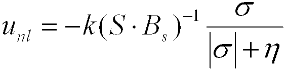
ここで、ulは制御システム10の状態が切換超平面の上を滑ってゆくようにさせる線形制御入力であり、unlは制御システム10の状態が切換超平面の方へ向かうようにさせる非線形制御入力である。線形制御入力ulは、数式6によって表され、非線形制御入力unlは数式7によって表される。
![]()
![]()
高速で移動する工作機械に関して、移動中の追従性を向上させるために、通常、速度及び加速度のフィードフォワード補償が行われる。このような特定の場合、切換関数σは、数式8によって表され、線形制御入力ulは数式9によって表される。
![]()
![]()
![]()
![]()
図6中にイラストされた位置制御装置では、指令位置rを微分する微分器46が指令速度rdotを発生し、指令速度rdotを微分する微分器47が指令加速度rddotを発生する。フィードフォーワード補償器61がゲインAffを用いて指令速度rdotを増幅し、フィードフォワード補償器62がゲインCffを用いて指令位置rを増幅する。乗算器74の出力S・zと、フィードフォワード補償器61とフィードフォワード補償器62の出力とが加算器75へ供給され、切換関数σが加算器75から平滑関数76へ送信される。平滑関数76からの出力がブロック77に入力され、ブロック77は数式7に基づいて非線形制御入力unlを加算器78へ送る。フィードフォワード補償器51がゲインAffを用いて指令加速度rddotを増幅し、フィードフォワード補償器52がゲインCffを用いて指令速度rdotを増幅する。フィードフォワード補償器51とフィードフォワード補償器52の出力はそれぞれブロック53とブロック54へ送信され、指令位置rとベクトルzはそれぞれブロック55とブロック56へ送信される。線形制御入力ulが、数式9に基づいて、ブロック53、ブロック54、ブロック55、ブロック56の出力として発生する。加算器78は、スライディングモード制御器50の出力である制御入力uすなわちq軸電流Iqを発生する。スライディングモード制御器50は、制御入力uを変化させることによって制御システム10の状態を切換超平面上に制御する。
移動中にサーボモータが指令入力に十分に追従するようスライディングモード制御器50中のゲインをサーボ系に応じて調整しなければならない。もし、積分値vのゲインに相当する、ブロック74中の要素S1を増大させると、ステッピング応答に望ましくないオーバシュートが起こるおそれがある。
The gain in the
本発明の目的は、先行技術の位置制御システムに見られる不都合、特に、移動中の追従性を損なうことなくオーバシュートを防止することに関わる不都合に取り組むことである。 It is an object of the present invention to address the disadvantages found in prior art position control systems, particularly those associated with preventing overshoot without compromising followability during movement.
本発明によれば、サーボモータとサーボモータによって駆動される移動体を含む制御システムの位置を指令値に追従させる位置制御装置は、数式10に従って指令位置rと制御システムの状態変数xとを受け取りサーボモータへ制御入力uを提供するスライディングモード制御器を含む。
数式10において、θはフィードバック位置、θdotはフィードバック速度である。位置制御装置は、また、フィードバック速度θdotに基づいて制御入力uを補償する外乱変数補償器を含み、超平面行列Sを[S2 S3]としてスライディングモード制御器中の切換関数σがS・xを含む。
In
好ましくは、指令速度rdot、指令加速度rddot、ゲインとしてのCff、Affが、スライディングモード制御器に入力される。切換関数σは数式11によって表される。
![]()
![]()
第2の側面において、本発明は、サーボモータとサーボモータによって駆動される移動体を含む制御システムの位置を指令値に追従させる位置制御装置である。その位置制御装置は、積分要素を用いることなく指令位置rと制御システムの状態変数xとを受け取りサーボモータへ制御入力uを提供するスライディングモード制御器を含む。ここで、状態変数xは、θをフィードバック位置、θdotをフィードバック速度として数式10によって表される。位置制御装置は、さらに、フィードバック速度θdotに基づいて制御入力uを補償する外乱変数補償器を含む。
In a second aspect, the present invention is a position control device that causes a position of a control system including a servo motor and a moving body driven by the servo motor to follow a command value. The position controller includes a sliding mode controller that receives the command position r and the control system state variable x without using an integral element and provides a control input u to the servo motor. Here, the state variable x is expressed by
この簡単な要約は発明の本質を即座に理解できるように提供された。発明の好適な実施例の下記の詳細な説明を添付の図面と関連させて参照することによって、発明をより完全に理解できる。他の実施例を利用したり、本発明の範囲から逸脱することなく変更を加えることができることが理解される。 This brief summary has been provided so that the nature of the invention may be understood quickly. A more complete understanding of the invention can be obtained by reference to the following detailed description of the preferred embodiment of the invention in connection with the accompanying drawings. It is understood that other embodiments may be utilized and changes may be made without departing from the scope of the present invention.
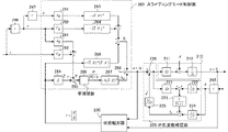
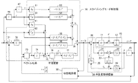
図1は、本発明による位置制御装置の一例をイラストしている。位置制御装置は、制御入力uを制御システムへ供給するスライディングモード制御器と、外乱に応答して制御入力uを補償する外乱変数補償器と、状態変数xを観測する状態観測器とを含む。 FIG. 1 illustrates an example of a position control device according to the present invention. The position control device includes a sliding mode controller that supplies the control input u to the control system, a disturbance variable compensator that compensates the control input u in response to the disturbance, and a state observer that observes the state variable x.
スライディングモード制御器260は、いかなる積分要素も含んでいない。スライディングモード制御器260の内部では、指令位置rとフィードバック位置yとの偏差の積分値は切換関数へ供給されていない。外乱変数補償器220は全ての偏差を外乱と見なして補償する。切換関数は以下の通り表される。
数式13中の切換関数と超平面行列は、数式4中のそれらと区別するためにσbarとSbarを用いて表されている。状態観測器230は、フィードバック位置yと制御入力uを入力として受け取り、状態変数xをスライディングモード制御器260へ供給する。乗算器284を用いて状態変数xに超平面行列Sbarが掛けられる。
The switching function and hyperplane matrix in
スライディングモード制御器260も、数式5の制御則に従うものとする。線形及び非線形制御入力はそれぞれ数式14及び15によって表される。
![]()
![]()
![]()
![]()
![]()
![]()
数値制御装置(図示されていない)からの指令位置rがブロック262へ供給される。指令速度rdotはフィードフォワード補償器252とフィードフォワード補償器261へ送られ、指令加速度rddotはフィードフォワード補償器251へ送られる。乗算器284の出力Sbar・xと、フィードフォワード補償器261とフィードフォワード補償器262の出力とが加算器285へ供給され、切換関数σbarが加算器285から平滑関数286へ送られる。平滑関数286の出力がブロック287に入力され、ブロック287は数式15に基づいて非線形制御入力unlbarを加算器288へ送る。フィードフォワード補償器251とフィードフォワード補償器252の出力が、それぞれブロック263とブロック264へ送信され、状態変数xはブロック268へ送られる。線形制御入力ulbarは、数式17に基づいて、ブロック263、ブロック264、ブロック268の出力から得られる。加算器288は、スライディングモード制御器260の出力として制御入力uすなわちq軸電流Iqを発生する。スライディングモード制御器260は制御入力uの切換によって制御システム210の状態を切換超平面の上に拘束する。
A command position r from a numerical controller (not shown) is supplied to block 262. The command speed rdot is sent to the
制御入力uすなわちq軸電流Iqと、フィードバック速度は、外乱変数補償器220へ供給され、外乱変数補償器220は外乱トルクに応答して制御入力uを補償する。q軸電流Iqは乗算器221でトルク定数Ktが掛けられる。フィードバック速度は測定速度θdotまたは適当な状態観測器から出力された推定速度である。測定位置θを微分する微分器245は測定速度θdotを出力し、この測定速度θdotは乗算器222と乗算器224の内部でJ/Tが掛けられる。ここで、Tはローパスフィルタ223の時定数である。乗算器221と乗算器222の出力の和は、sがラプラス演算子を表すローパスフィルタ223へ供給される。推定外乱トルクτLhatは、ローパスフィルタ223の出力から乗算器224の出力を減じることによって得られる。乗算器225は、推定外乱トルクτLhatに1/Ktを掛け、推定外乱トルクτLhatをq軸電流に変換させて推定外乱dhatを発生する。加算器226は制御入力uと推定外乱dhatの和を制御システム210へ供給する。
The control input u, that is, the q-axis current Iq and the feedback speed are supplied to the
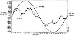
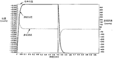
図2中に示されるように、図1の位置制御装置中のゲインは最大追従誤差が10カウントより小さくなるように調整され、図3中のグラフは、そのような状態で測定されたステップ応答を示している。 As shown in FIG. 2, the gain in the position controller of FIG. 1 is adjusted so that the maximum tracking error is less than 10 counts, and the graph in FIG. 3 shows the step response measured in such a state. Is shown.
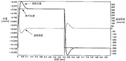
図4中に示されるように、図6の位置制御装置中のゲインも、また、最大追従誤差が10カウントより小さくなるように調整された。図5のグラフは、そのような状態で測定されたステップ応答を示している。図3中に示されるように、本発明の位置制御装置は、追従誤差が小さい状態でオーバシュートの発生を防止することができる。 As shown in FIG. 4, the gain in the position controller of FIG. 6 was also adjusted so that the maximum tracking error was less than 10 counts. The graph of FIG. 5 shows the step response measured in such a state. As shown in FIG. 3, the position control device of the present invention can prevent the occurrence of overshoot in a state where the tracking error is small.
本発明はある特定の詳細な実施例を用いて説明された。本発明は上述の実施例に限定されることなく、本発明の精神および範囲から逸脱することなく当業者によって種々の変更や変形を加えることができることが理解されよう。 The invention has been described using certain specific details. It will be understood that the present invention is not limited to the embodiments described above and that various changes and modifications can be made by those skilled in the art without departing from the spirit and scope of the invention.
10、制御システム
11、モータトルク定数
12、伝達関数
20、外乱変数補償器
23、ローパスフィルタ
26、75、78、加算器
30、状態観測器
45、46、47、微分器
50、スライディングモード制御器
51、52、61、62、フィードフォワード補償器
71、減算器
72、積分器
73、ベクトル化器
75、78、加算器
76、平滑関数
210、制御システム
211、モータトルク定数
212、伝達関数
220、外乱変数補償器
223、ローパスフィルタ
226、285、288、加算器
230、状態観測器
245、246、247、微分器
251、252、261、262、フィードフォワード補償器
260、スライディングモード制御器
285、288、加算器
286、平滑関数
10, control system 11, motor torque constant 12, transfer function 20,
Claims (12)
θをフィードバック位置、θdotをフィードバック速度として、状態変数xが数式1の通り表され、
超平面行列Sを[S2 S3]としてスライディングモード制御器中の切換関数σがS・xを含む位置制御装置。 In a position control device that causes the position of a control system including a servo motor and a moving body driven by the servo motor to follow the command value,
The state variable x is expressed as Equation 1, where θ is the feedback position and θdot is the feedback speed.
A position control device in which the hyperplane matrix S is [S2 S3] and the switching function σ in the sliding mode controller includes S · x.
θをフィードバック位置、θdotをフィードバック速度として、状態変数xが数式1の通り表され、
The state variable x is expressed as Equation 1, where θ is the feedback position and θdot is the feedback speed.
Applications Claiming Priority (1)
| Application Number | Priority Date | Filing Date | Title |
|---|---|---|---|
| US10/816,864 US7190140B2 (en) | 2004-04-05 | 2004-04-05 | Sliding mode controller position control device |
Publications (1)
| Publication Number | Publication Date |
|---|---|
| JP2005293564A true JP2005293564A (en) | 2005-10-20 |
Family
ID=35055422
Family Applications (1)
| Application Number | Title | Priority Date | Filing Date |
|---|---|---|---|
| JP2005064832A Pending JP2005293564A (en) | 2004-04-05 | 2005-03-09 | Position control device having sliding mode controller |
Country Status (2)
| Country | Link |
|---|---|
| US (1) | US7190140B2 (en) |
| JP (1) | JP2005293564A (en) |
Cited By (3)
| Publication number | Priority date | Publication date | Assignee | Title |
|---|---|---|---|---|
| KR100932622B1 (en) * | 2007-08-21 | 2009-12-17 | 성균관대학교산학협력단 | Optimal Control Method Based on Sliding Mode Control Applied to High Precision Positioning System |
| CN103336483A (en) * | 2013-05-22 | 2013-10-02 | 沈阳工业大学 | Control methods for time-varying sliding mode variable structure and for cross-coupling control magnetic suspension system |
| KR101434310B1 (en) | 2013-05-22 | 2014-08-26 | 현대로템 주식회사 | Stabilization enhancement method of drive unit mounted on moving equipment and system, that moving equipment |
Families Citing this family (10)
| Publication number | Priority date | Publication date | Assignee | Title |
|---|---|---|---|---|
| US8200347B2 (en) * | 2009-01-22 | 2012-06-12 | Mitsubishi Electric Research Laboratories, Inc. | Method and apparatus for hybrid resetting states proportional-integral-derivative and lag controllers |
| JP5530159B2 (en) * | 2009-11-30 | 2014-06-25 | ローム株式会社 | Motor control circuit, control method, and electronic apparatus with imaging function using the same |
| JP5723582B2 (en) * | 2010-11-30 | 2015-05-27 | インターナショナル・ビジネス・マシーンズ・コーポレーションInternational Business Machines Corporation | Method, program and system for configuring controller in sliding mode control system |
| WO2014010020A1 (en) * | 2012-07-09 | 2014-01-16 | 株式会社安川電機 | Motor control device and motor system |
| CN112947310B (en) * | 2021-01-28 | 2022-07-08 | 清华大学 | Rotary servo motor track precompensation method and device based on prediction model |
| CN116833993A (en) * | 2022-03-23 | 2023-10-03 | 北京理工大学 | Bionic dummy arm accurate tracking control system and method |
| CN114967466B (en) * | 2022-06-02 | 2025-02-07 | 安徽工业大学 | A preset performance output feedback control method for an electro-hydraulic servo system based on disturbance compensation and full-state constraints |
| CN115903908B (en) * | 2022-12-14 | 2023-07-11 | 南京航空航天大学 | Bee colony unmanned aerial vehicle fault-tolerant cooperative control method based on rapid terminal sliding mode |
| CN116300683B (en) * | 2023-03-20 | 2026-03-17 | 沈阳工业大学 | Device and method for improving the contour accuracy of a direct-drive XY motion platform servo system |
| CN119036436B (en) * | 2024-06-26 | 2025-10-03 | 天津大学 | Dual-loop position control method for universal pneumatic flexible robotic arm based on digital twin |
Family Cites Families (25)
| Publication number | Priority date | Publication date | Assignee | Title |
|---|---|---|---|---|
| JPH02297603A (en) | 1989-05-12 | 1990-12-10 | Fanuc Ltd | Servo control system using sliding mode and also disturbance estimation observer |
| JPH0325505A (en) | 1989-06-22 | 1991-02-04 | Toyo Electric Mfg Co Ltd | Multifunction controller |
| JPH03118618A (en) * | 1989-09-30 | 1991-05-21 | Fanuc Ltd | Control system applying sliding mode control having damping effect |
| US4999553A (en) * | 1989-12-28 | 1991-03-12 | The United States Of America As Represented By The Administrator Of The National Aeronautics And Space Administration | Method and apparatus for configuration control of redundant robots |
| US5019958A (en) * | 1990-02-12 | 1991-05-28 | Varga Ljubomir D | Generalized synthesis of control systems of zero-order/instantaneous response and infinite disturbance rejection ratio |
| JPH05134758A (en) * | 1991-05-17 | 1993-06-01 | Fanuc Ltd | Servo motor control system |
| DE69227434T2 (en) * | 1991-11-22 | 1999-03-18 | Fujitsu Ltd., Kawasaki, Kanagawa | Position control system |
| JPH05216504A (en) * | 1992-02-06 | 1993-08-27 | Fanuc Ltd | Adaptive sliding mode control system for control object including spring system |
| US5369345A (en) * | 1992-03-31 | 1994-11-29 | Seagate Technology, Inc. | Method and apparatus for adaptive control |
| JP2999330B2 (en) | 1992-05-29 | 2000-01-17 | 株式会社神戸製鋼所 | Control method using sliding mode control system |
| US5510939A (en) * | 1992-07-16 | 1996-04-23 | Micropolis Corporation | Disk drive with adaptive positioning |
| US5379210A (en) * | 1992-07-24 | 1995-01-03 | M&M Software Products, Inc. | Natural tracking controller |
| US5475291A (en) * | 1992-12-10 | 1995-12-12 | Matsushita Electric Industrial Co., Ltd. | Adjustment device for adjusting control parameters of a servo motor and an adjustment method therefor |
| JP3196390B2 (en) * | 1992-12-25 | 2001-08-06 | 富士電機株式会社 | Parameter identifier |
| US5585976A (en) * | 1994-06-22 | 1996-12-17 | Seagate Technology, Inc. | Digital sector servo incorporating repeatable run out tracking |
| US5847895A (en) * | 1995-03-07 | 1998-12-08 | Cirrus Logic, Inc. | Chatter reduction in sliding mode control of a disk drive actuator |
| US5631999A (en) * | 1995-09-06 | 1997-05-20 | Seagate Technology Inc. | Adaptive compensation for hard disc drive spindle motor manufacturing tolerances |
| US5982721A (en) * | 1996-03-29 | 1999-11-09 | Cirrus Logic, Inc. | Optical disc drive comprising switching gains for forcing phase states to follow a sliding line trajectory in a servo system |
| JP3299109B2 (en) * | 1996-04-05 | 2002-07-08 | 本田技研工業株式会社 | Sliding mode control method |
| US6278899B1 (en) * | 1996-05-06 | 2001-08-21 | Pavilion Technologies, Inc. | Method for on-line optimization of a plant |
| US6381504B1 (en) * | 1996-05-06 | 2002-04-30 | Pavilion Technologies, Inc. | Method for optimizing a plant with multiple inputs |
| US6046878A (en) * | 1997-04-30 | 2000-04-04 | Seagate Technology, Inc. | Object positioning using discrete sliding mode control with variable parameters |
| KR19980083174A (en) * | 1997-05-12 | 1998-12-05 | 윤종용 | Vibration Suppression Control Method and Control Apparatus of Resonance System |
| JP3297643B2 (en) * | 1997-10-14 | 2002-07-02 | 東芝機械株式会社 | Servo control method and servo control device for feed drive system |
| KR100475121B1 (en) * | 2002-12-16 | 2005-03-10 | 삼성전자주식회사 | Method for controlling a settling servo of disc drive, method for estimation a coefficient of accelation of VCM actuator and apparatuses therefor |
-
2004
- 2004-04-05 US US10/816,864 patent/US7190140B2/en not_active Expired - Lifetime
-
2005
- 2005-03-09 JP JP2005064832A patent/JP2005293564A/en active Pending
Cited By (3)
| Publication number | Priority date | Publication date | Assignee | Title |
|---|---|---|---|---|
| KR100932622B1 (en) * | 2007-08-21 | 2009-12-17 | 성균관대학교산학협력단 | Optimal Control Method Based on Sliding Mode Control Applied to High Precision Positioning System |
| CN103336483A (en) * | 2013-05-22 | 2013-10-02 | 沈阳工业大学 | Control methods for time-varying sliding mode variable structure and for cross-coupling control magnetic suspension system |
| KR101434310B1 (en) | 2013-05-22 | 2014-08-26 | 현대로템 주식회사 | Stabilization enhancement method of drive unit mounted on moving equipment and system, that moving equipment |
Also Published As
| Publication number | Publication date |
|---|---|
| US20050222695A1 (en) | 2005-10-06 |
| US7190140B2 (en) | 2007-03-13 |
Similar Documents
| Publication | Publication Date | Title |
|---|---|---|
| JP4665096B2 (en) | Motion controller used in machine tool with sliding mode controller | |
| KR940003005B1 (en) | Arrangement for speed regulation of electric motor | |
| JP4760912B2 (en) | Servo control device | |
| EP2105810A2 (en) | Apparatus and method for controlling a system | |
| JP5791815B2 (en) | Machine tool feed axis control method and feed axis control apparatus | |
| JP2005293564A (en) | Position control device having sliding mode controller | |
| JP2005301508A (en) | Control unit | |
| JP2009245420A (en) | System controller and system control method | |
| JP4867105B2 (en) | Numerical controller | |
| EP1560325B1 (en) | Position controller of motor | |
| JPWO2014167808A1 (en) | Motor drive device | |
| CN104730973A (en) | Motor control device | |
| JP2010049599A (en) | Machine tool | |
| JP4226420B2 (en) | Position control device | |
| US20070007927A1 (en) | Position controller and controlling method therefor | |
| JP4925056B2 (en) | Motor position control device | |
| Jaafar et al. | Sliding mode control with dirty derivatives filter for rigid robot manipulators | |
| JP5660482B2 (en) | Control method and control device for feed drive system of machine tool | |
| JP2014117787A (en) | Controller | |
| Qin et al. | Nonlinear discrete observer for flexibility compensation of industrial robots | |
| Ren et al. | Joint torque control of a collaborative robot based on active disturbance rejection with the consideration of actuator delay | |
| JP2014176291A (en) | Feed axis control method and feed axis control device for machine tool | |
| JP2004102556A (en) | Positioning controller | |
| JP2007306779A (en) | Motor control device | |
| JP2007334614A (en) | Position control device |
Legal Events
| Date | Code | Title | Description |
|---|---|---|---|
| A621 | Written request for application examination |
Free format text: JAPANESE INTERMEDIATE CODE: A621 Effective date: 20070920 |
|
| A977 | Report on retrieval |
Free format text: JAPANESE INTERMEDIATE CODE: A971007 Effective date: 20090623 |
|
| A131 | Notification of reasons for refusal |
Free format text: JAPANESE INTERMEDIATE CODE: A131 Effective date: 20090707 |
|
| A02 | Decision of refusal |
Free format text: JAPANESE INTERMEDIATE CODE: A02 Effective date: 20091110 |