JP2005293315A - Data mirror type cluster system and synchronous control method for it - Google Patents
Data mirror type cluster system and synchronous control method for it Download PDFInfo
- Publication number
- JP2005293315A JP2005293315A JP2004108392A JP2004108392A JP2005293315A JP 2005293315 A JP2005293315 A JP 2005293315A JP 2004108392 A JP2004108392 A JP 2004108392A JP 2004108392 A JP2004108392 A JP 2004108392A JP 2005293315 A JP2005293315 A JP 2005293315A
- Authority
- JP
- Japan
- Prior art keywords
- data
- server device
- shared memory
- database
- standby
- Prior art date
- Legal status (The legal status is an assumption and is not a legal conclusion. Google has not performed a legal analysis and makes no representation as to the accuracy of the status listed.)
- Pending
Links
Images
Classifications
-
- G—PHYSICS
- G06—COMPUTING OR CALCULATING; COUNTING
- G06F—ELECTRIC DIGITAL DATA PROCESSING
- G06F11/00—Error detection; Error correction; Monitoring
- G06F11/07—Responding to the occurrence of a fault, e.g. fault tolerance
- G06F11/16—Error detection or correction of the data by redundancy in hardware
- G06F11/20—Error detection or correction of the data by redundancy in hardware using active fault-masking, e.g. by switching out faulty elements or by switching in spare elements
- G06F11/2097—Error detection or correction of the data by redundancy in hardware using active fault-masking, e.g. by switching out faulty elements or by switching in spare elements maintaining the standby controller/processing unit updated
-
- G—PHYSICS
- G06—COMPUTING OR CALCULATING; COUNTING
- G06F—ELECTRIC DIGITAL DATA PROCESSING
- G06F11/00—Error detection; Error correction; Monitoring
- G06F11/07—Responding to the occurrence of a fault, e.g. fault tolerance
- G06F11/16—Error detection or correction of the data by redundancy in hardware
- G06F11/20—Error detection or correction of the data by redundancy in hardware using active fault-masking, e.g. by switching out faulty elements or by switching in spare elements
- G06F11/2053—Error detection or correction of the data by redundancy in hardware using active fault-masking, e.g. by switching out faulty elements or by switching in spare elements where persistent mass storage functionality or persistent mass storage control functionality is redundant
- G06F11/2056—Error detection or correction of the data by redundancy in hardware using active fault-masking, e.g. by switching out faulty elements or by switching in spare elements where persistent mass storage functionality or persistent mass storage control functionality is redundant by mirroring
Landscapes
- Engineering & Computer Science (AREA)
- Theoretical Computer Science (AREA)
- Quality & Reliability (AREA)
- Physics & Mathematics (AREA)
- General Engineering & Computer Science (AREA)
- General Physics & Mathematics (AREA)
- Hardware Redundancy (AREA)
- Information Retrieval, Db Structures And Fs Structures Therefor (AREA)
Abstract
Description
本発明は、データミラー型クラスタシステムに関し、特に、複数のサーバのデータを高速に同期させることが可能なクラスタシステムに関する。 The present invention relates to a data mirror type cluster system, and more particularly to a cluster system capable of synchronizing data of a plurality of servers at high speed.
データミラー型のクラスタシステムでは、LANなどのインターコネクトを介してサーバ間のデータを同期させている。しかし、インターコネクトとして、TCP/IPなどを使用する場合にはそのプロトコルの為のソフトウェアスタックが深く、又I/Oカードを介して通信を行うためLatency(待ち時間)が大きくなる。 In a data mirror type cluster system, data between servers is synchronized via an interconnect such as a LAN. However, when TCP / IP or the like is used as an interconnect, the software stack for the protocol is deep, and since communication is performed via an I / O card, Latency (waiting time) increases.
データミラー型のクラスタシステムは、動作系で更新されるデータベースのデータを、随時待機系にコピーし、データの同期を取る必要があり、このようにLatencyが大きいシステムでは、データ同期のタイミング間隔が大きくなり、一回の同期で転送するデータの量が大きくなる。結果、障害が発生して同期に失敗すると、失われる情報量も大きくなることになる。 In a data mirror type cluster system, it is necessary to copy the database data updated in the operation system to the standby system at any time and synchronize the data. In such a system with a large latency, the data synchronization timing interval is The amount of data transferred in one synchronization increases. As a result, when a failure occurs and synchronization fails, the amount of information lost increases.
特許文献1は、クラスタシステムの同期制御方法を開示するが、Latencyを小さくするための工夫は開示されていない。
また、特許文献2は、二重化されたシステムにおいて自系アドレス空間と他系アドレス空間とをもち、自系と他系のアドレスの対象性を持つ構成が開示されているが、この構成では、自系と他系のアドレスの管理が複雑である。
また、特許文献3には、各コンピュータ装置に第1と第2の主記憶装置を配置し、一方の装置の第1の主記憶装置へのデータの格納があると、DMA(Direct
Memory Access)転送により、他方の装置の第2の主記憶装置に該当データを書き込むことによりデータの同期を取る方法が開示されている。しかし、この構成では、第1と第2の主記憶の管理が複雑であるという問題が生ずる。
Further, Patent Document 2 discloses a configuration in which a self-system address space and a non-system address space are included in a duplex system and the target system has a target address of the self-system and the other system. Management of system and other system addresses is complicated.
Further, in Patent Document 3, when first and second main storage devices are arranged in each computer device and data is stored in the first main storage device of one device, DMA (Direct
A method of synchronizing data by writing the corresponding data in the second main storage device of the other device by memory access transfer is disclosed. However, this configuration has a problem that the management of the first and second main memories is complicated.
本発明は、上記実情に鑑みてなされたものであり、本発明は、障害発生時にミラー同期に失敗するデータの量を少なくすることを目的とする。
また、本発明は、制御・管理が容易なクラスタシステムとその制御方法を提供することを他の目的とする。
The present invention has been made in view of the above circumstances, and an object of the present invention is to reduce the amount of data that fails in mirror synchronization when a failure occurs.
Another object of the present invention is to provide a cluster system that can be easily controlled and managed, and a control method therefor.
上記目的を達成するため、この発明のデータミラー型クラスタシステムは、
一台が運用系、少なくとももう一台が待機系として動作するサーバ装置から構成され、運用系データベース上のデータ変更を待機系のデータベースに反映するデータミラー型クラスタシステムであって、
各サーバ装置は、それぞれのデータベースと、両サーバ装置からアクセス可能な共有メモリとを備え、トランザクションを相手サーバ装置に転送できるインターコネクトにより相互に接続されており、
各サーバ装置は、運用系として動作しているときに、データベース上のデータの変更を共有メモリに書き込む運用系メモリドライバ手段と、
待機系として動作しているときに、前記インターコネクトを介して共有メモリ上に転送されてきたデータをデータベースに書き込む待機系メモリドライバ手段と、
を備えることを特徴とする。
In order to achieve the above object, a data mirror type cluster system of the present invention provides:
A data mirror type cluster system that consists of server devices that operate as an active system and at least one as a standby system, and that reflects data changes on the active database to the standby database.
Each server device includes a database and a shared memory that can be accessed from both server devices, and is interconnected by an interconnect that can transfer transactions to the partner server device.
Each server device, when operating as an operational system, an operational memory driver means for writing data changes in the database to the shared memory;
When operating as a standby system, standby system memory driver means for writing data transferred to the shared memory via the interconnect to the database; and
It is characterized by providing.
例えば、前記運用系メモリドライバ手段は、前記インターコネクトを介して、前記待機系サーバ装置に存在する共有メモリ上にデータを直接書き込む。 For example, the operational memory driver means directly writes data on the shared memory existing in the standby server device via the interconnect.
前記インターコネクトは、多重化されることが望ましい。 The interconnects are preferably multiplexed.
各サーバ装置は、外部回路と接続するための入出力ポートを備え、前記インターコネクトは、一方のサーバ装置が他方のサーバ装置の共有メモリにアクセスするための専用回路である、ことが望ましい。 Each server device includes an input / output port for connection to an external circuit, and the interconnect is preferably a dedicated circuit for one server device to access a shared memory of the other server device.
上記目的を達成するため、この発明の同期制御方法は、
互いにアクセス可能な共有メモリを備え、相互に接続された複数台のサーバ装置から構成され、運用系データベース上のデータ変更を待機系のデータベースに反映するデータミラー型クラスタシステムの同期制御方法であって、
運用系サーバ装置のデータベース上のデータの更新を検出し、運用系サーバ装置に物理的に存在する共有メモリに書き込むステップと、
前記運用系サーバ装置上の共有メモリに書き込まれたデータを前記インターコネクトを介して前記待機系サーバ装置に物理的に存在する共有メモリ上に反映するステップと、
待機系サーバ装置の共有メモリ上のデータの更新を検出し、待機系サーバ装置のデータベースに反映するステップと、
を備えることを特徴とする。
In order to achieve the above object, the synchronization control method of the present invention provides:
A synchronization control method for a data mirror type cluster system comprising a plurality of mutually connected server devices having a shared memory accessible to each other, and reflecting data changes on an active database to a standby database. ,
Detecting update of data on the database of the active server device and writing to the shared memory physically existing in the active server device;
Reflecting the data written in the shared memory on the active server device on the shared memory physically existing in the standby server device via the interconnect;
Detecting the update of data on the shared memory of the standby server device and reflecting it in the database of the standby server device;
It is characterized by providing.
本発明は、複数のサーバ装置で共有メモリとインターコネクタによりデータの同期を取るため、高速でLatencyの低いミラー型クラスタを構成することができる。これにより、データの可用性が従来に比して向上し、障害発生時のロールバック時間が短縮され、システムの可用性の向上を図る事が出来る。また、複数のサーバ装置で共用メモリを使用するため、管理が容易である。 According to the present invention, a plurality of server apparatuses synchronize data with a shared memory and an interconnector, so that a mirror type cluster having a high speed and low latency can be configured. As a result, the availability of data is improved as compared with the conventional case, the rollback time when a failure occurs is shortened, and the availability of the system can be improved. Further, since a shared memory is used by a plurality of server devices, management is easy.
この発明の実施の形態に係るデータミラー型クラスタシステムを図面を参照して説明する。
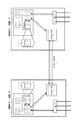
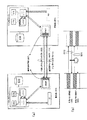
本実施の形態のデータミラー型クラスタシステム11は、図1に示すように、2台のサーバ装置12と13とから構成される。サーバ装置12と13とは、それぞれ、CPU(Central
Processing Unit)からのトランザクションを直接他のノード(サーバ装置)13と12に高速転送できるインターコネクト14により相互に接続されており、データミラー型クラスタを構成している。
A data mirror type cluster system according to an embodiment of the present invention will be described with reference to the drawings.
As shown in FIG. 1, the data mirror type cluster system 11 of the present embodiment is composed of two
Transactions from the processing unit are directly connected to each other by
サーバ装置12は、CPUモジュール21とデータベース22とクロスバースイッチ(XBAR SW)23と、I/O(Input/Output)装置24を備える。
CPUモジュール21は、1又は複数のCPU25と、メモリ26と、メモリコントローラ27とを備える。
The
The
CPU25は、このサーバ装置12の制御・データ処理を実行する。
メモリ26は主記憶装置、補助記憶装置等を含む。メモリ26の一部は、サーバ装置13からもインターコネクト14を介して直接アクセス(リード/ライト)可能な共用メモリ29として機能する。メモリコントローラ27は、CPU25の制御下に、メモリ26及びデータベース22をアクセスするためのものであり、共有メモリ29を監視する共有メモリドライバを備える。
The CPU 25 executes control / data processing of the
The memory 26 includes a main storage device, an auxiliary storage device, and the like. A part of the memory 26 functions as a shared memory 29 that can be directly accessed (read / written) from the
データベース22は、物理的には、I/O装置(ポート)24に接続されており、その内容がメモリ26に展開されており、メモリコントローラ27によりアクセス制御が行われる。
クロスバースイッチ23は、メモリコントローラ27とインターコネクト14に接続されており、メモリコントローラ27とインターコネクト14間のデータの伝送を制御する。
I/O装置24は、メモリコントローラ27に接続されており、外部装置との間で情報を送受信する。I/O装置24は、外部装置とデータを送受信する点においては、インターコネクト14と共通するが、インターコネクト14と異なり汎用性を有し、一般に、外部との通信のためにドライバの起動、初期化などの処理が必要で、高速性においてインターコネクト14に劣る。
The
The crossbar switch 23 is connected to the memory controller 27 and the
The I / O device 24 is connected to the memory controller 27 and transmits / receives information to / from an external device. The I / O device 24 is common to the
サーバ装置13は、実質的にサーバ装置12と同様の構成を有し、CPUモジュール31とデータベース32とクロスバースイッチ33とI/O装置34とを備える。
CPUモジュール31は、1又は複数のCPU35と、メモリ36と、メモリコントローラ37とを備える。
The
The CPU module 31 includes one or more CPUs 35, a memory 36, and a memory controller 37.
CPU35は、このサーバ装置13の制御・データ処理を実行する。
メモリ36は主記憶装置、補助記憶装置等を含む。メモリ36の一部は、サーバ装置12からもインターコネクト14を介して直接アクセス(リード/ライト)可能な共用メモリ29として機能する。メモリコントローラ37は、CPU35の制御下に、メモリ36及びデータベース32をアクセスするためのものであり、共有メモリ39を監視する共有メモリドライバを備える。
The CPU 35 executes control / data processing of the
The memory 36 includes a main storage device, an auxiliary storage device, and the like. A part of the memory 36 functions as a shared memory 29 that can be directly accessed (read / written) from the
データベース32は、I/O装置24に接続されており、メモリ36に展開され、メモリコントローラ37によりアクセス制御が行われる。
クロスバースイッチ33は、メモリコントローラ37とインターコネクト14に接続されており、メモリコントローラ37とインターコネクト14間のデータの伝送を制御する。
The database 32 is connected to the I / O device 24, expanded in the memory 36, and access control is performed by the memory controller 37.
The crossbar switch 33 is connected to the memory controller 37 and the
2台のサーバ装置12,13のうち、一台は運用系として動作し一台は待機系として動作する。図1に示す例では、サーバ装置12が運用系サーバ装置として動作し、サーバ装置13が待機系サーバ装置として動作している。
Of the two
また、各サーバ装置12,13の共有メモリ29,39へのリード/ライトは、インターコネクト14を通じて相手の共有メモリ39,29にもリード/ライトされる。
In addition, the read / write to the shared memories 29 and 39 of the
インターコネクト14は、高速でデータ転送が可能な専用ラインなどから構成されており、インターコネクト自体も二重化されている。
The
運用系サーバ装置12でデータベース22の更新があった場合、運用系サーバ装置12は自らのデータベース22の更新を行うと共に、共有メモリ29に変更のあったデータを書き込む。書き込まれたデータは、クロスバースイッチ23とインターコネクト14とクロスバースイッチ33を通じて、待機系サーバ装置13の共有メモリ36に転送され書き込まれる。待機系サーバ装置13のメモリコントローラ37内の共有メモリドライバは、共有メモリ39に書き込まれたデータをデータベース32に反映することによってデータミラー型のクラスタを実現する。
When the
運用系サーバ装置12で障害が発生した場合、アプリケーションの実行は待機系サーバ装置13に引き継がれる。この時、同期がなされていない(コミットされていない)データは、失敗データとして破棄され、再実行をする必要がある。本発明に於けるインターコネクト14を用いた共有メモリ29,39を用いることによって、運用系/待機系間のデータ同期間隔を短く取るとることが可能となり、これまでのミラー型クラスタに比べ破棄されるデータを少なく抑える事ができる。
When a failure occurs in the
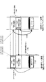
次に、上記構成のデータミラー型クラスタシステムのメモリの割付について図2を参照して説明する。
図2は運用系サーバ装置12と待機系サーバ装置13それぞれのメモリマップを示す。前述したように、運用系サーバ装置12と待機系サーバ装置13とは、互いにリードライト可能な共有メモリ29と39とを有しており、共有メモリ29と39にはそれぞれ物理メモリの一部として、論理アドレスが付与されている。
Next, the memory allocation of the data mirror type cluster system having the above configuration will be described with reference to FIG.
FIG. 2 shows a memory map of each of the
例えば、運用系サーバ装置12の論理メモリマップ101について考えると、運用系サーバ装置12に割り当てられている論理アドレスの一部が共有メモリ領域103により占められている。同様に、待機系サーバ装置13の論理メモリマップ102について考えると、待機系サーバ装置13に割り当てられている論理アドレスの一部が共有メモリ領域104により占められている。
For example, considering the logical memory map 101 of the
換言すると、運用系サーバ装置12に存在する共有メモリ29は、運用系サーバ装置12のCPU25からは論理アドレス103の空間として認識され、待機系サーバ装置13のCPU35からは論理アドレス104の空間として認識され、待機系サーバ装置13に存在する共有メモリ39には、運用系サーバ装置12のCPU25からは論理アドレス103の空間として認識され、待機系サーバ装置13のCPU35からは論理アドレス104の空間として認識される。
In other words, the shared memory 29 existing in the
次に、上記構成のクラスタシステムの動作を図2と図3を参照して説明する。
運用系サーバ装置12のメモリコントローラ27と待機系サーバ装置13のメモリコントローラ37では、それぞれ共有メモリ29と39を監視する共有メモリドライバが動作している。
Next, the operation of the cluster system configured as described above will be described with reference to FIGS.
In the memory controller 27 of the
運用系サーバ装置12(CPU25)は、データベース22上のデータ、例えば、顧客データベースなどのデータを変更する際には、メモリ26上に展開されているデータ(110)を変更する。
The operational server device 12 (CPU 25) changes the data (110) developed on the memory 26 when changing data on the
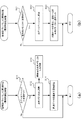
共有メモリ29と39を監視している運用系と待機系のドライバは、それぞれ、図3(a)、(b)に示す処理を、例えば定期的な割り込みで実行しており、まず、運用系サーバ装置12の共有メモリドライバは、図3(a)に示すように、データベースの変更(データ110)を検知し(ステップS11)、変更箇所のデータ110を共有メモリ29の論理アドレス108のエリアに書き込む(ステップS12)。この書き込みは、インターコネクト14を通じて待機側の共有メモリ39のエリア106に直接行われる(ステップS13)(運用側には論理アドレス108に対応する物理メモリは存在せず、待機系の共有メモリ39がインターコネクト14を介して見えているだけである)。続いて、待機系から同期データ受信完了通知を受信するのを待機する状態に入る(ステップS14)。なお、ステップS14の待機状態は、待機系から同期データ受信完了通知を受信することにより解除され、処理が終了する。一方、ステップS14の状態が所定時間以上継続する場合には、タイムアウトとして、エラー処理に移る。
The active and standby drivers that monitor the shared memories 29 and 39 execute the processing shown in FIGS. 3A and 3B, for example, by periodic interruption. As shown in FIG. 3A, the shared memory driver of the
一方、待機系サーバ装置13の共有メモリドライバは、図3(b)に示すように、共有メモリ39のエリア106に格納されているデータの変更を検知し(ステップS21)、自データベース32に変更を反映させる(111;ステップS22)。続いて、運用側のローカル物理メモリが反映されている共有メモリ39(エリア107)に対して同期データ受信完了を示す書き込み(ACK112)を行う(ステップS23)。同期データ受信完了の書き込み(ACK112)は、インターコネクト14を通じて共有メモリ29(運用側にローカルに存在する物理メモリ29(エリア105))に直接書き込まれる。運用側の共有メモリドライバはこれを検知して同期完了と認識し、ステップ14の待機を終了する。
On the other hand, the shared memory driver of the
この様に、本発明では共有メモリ(29,39;103/104)を使用して運用側と待機側のデータベースの同期をとる。 Thus, in the present invention, the database on the operation side and the standby side are synchronized using the shared memory (29, 39; 103/104).
運用系に障害が発生した場合、データミラー型のクラスタシステムでは同期化されていない(コミットされていない)データについては、同期化失敗として待機系のアプリケーションへ動作を引き継ぐ。この時、失敗したデータについて、再度登録を行うなどの処置が必要となる。 When a failure occurs in the active system, data synchronization (uncommitted) in the data mirror type cluster system is taken over to the standby application as a synchronization failure. At this time, it is necessary to take a measure such as re-registering the failed data.
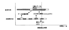
従来のデータミラー型クラスタでは、TCP/IPを使用するなどしてクラスタを構成していた。このため、図4に示すように、データ同期のLatency201が大きい。結果同期処理を頻繁に行う事ができなかった。この為、同期の為の変更データのサイズが大きくなり、障害発生時の破損データのサイズ(202)も大きくなる事から再登録に時間がかかっていた。 In the conventional data mirror type cluster, the cluster is configured by using TCP / IP. For this reason, as shown in FIG. 4, the latency 201 of data synchronization is large. Result synchronization processing could not be performed frequently. For this reason, the size of the change data for synchronization is increased, and the size (202) of the damaged data at the time of failure is also increased, so that re-registration takes time.
これに対し、本実施の形態の手法では、運用系のシステムが変更内容を共有メモリに書き込むだけで、待機系の共有メモリにも同様の変更が反映され、データベース32にも反映される。このように、Latencyの低い共有メモリを使用する事により、頻繁にデータ同期を行う事ができる。この為、障害発生の際のデータの破損(203)を小さくする事ができ、再登録時間を短縮することができる。 On the other hand, in the method according to the present embodiment, the same change is reflected in the standby shared memory and is also reflected in the database 32 only by the operation system writing the changed contents in the shared memory. Thus, frequent data synchronization can be performed by using a shared memory with a low latency. For this reason, it is possible to reduce the data corruption (203) when a failure occurs, and to shorten the re-registration time.
次に、図5(a)、(b)を参照して、共有メモリを実現するインターコネクト14に障害が発生した場合について説明する。
図5(a)に示すように、インターコネクト14は二重化されており、片方のデータパス(通常運用インターコネクト)301は通常運用時に使用され、もう一方のパス(代替運用インターコネクト)302は通常運用時のデータパスに障害が発生した際の代替えパスとして使用される。この事は、共有メモリ29,39を実現する為のインターコネクトに関しても二重化されているということを意味する。換言すれば、図5(b)に示すように、共有メモリが2セット配置されることを意味する。これにより、このミラー型クラスタシステムの可用性と信頼性を更に高める。
Next, with reference to FIGS. 5A and 5B, a case where a failure occurs in the
As shown in FIG. 5A, the
データのミラーリングを担当する共有メモリドライバは、共有メモリのアドレス(305/306)によって、どちらのデータパスを使用するかを選択する事ができる。今、共有メモリ領域1(305)で定義される通常運用時のデータパス(301)に障害が発生したとする。動作系(303)のメモリドライバは待機系(304)に対して書き込んだデータに対する同期完了の書き込みが行われない事をタイムアウトによって検知する(図3(a)、ステップS14参照)。同期タイムアウトを検知した動作系(303)のメモリドライバは、共有メモリのアドレスを共有メモリ領域2(306)に変更し、代替えパス側に対して再度同期データを書き込みデータの同期を完了させる。又、インターコネクトにはハードウエアでリンクの状態を検出する障害検出回路(307)が配置されている。この障害検出回路307は、二重化されているインターコネクト301と302の両方に障害が発生した場合、運用系/待機系共にハードウエアにより両インターコネクト301,302の障害を検知し、インターコネクト障害のフラグを立てる。待機系304のCPUは、アプリケーションに対して、自らのデータベースが無効であるというフラグをセットする。
The shared memory driver in charge of data mirroring can select which data path to use depending on the address (305/306) of the shared memory. Assume that a failure has occurred in the data path (301) during normal operation defined in the shared memory area 1 (305). The memory driver of the operation system (303) detects from the timeout that writing of completion of synchronization with respect to the data written to the standby system (304) is not performed (see FIG. 3 (a), step S14). The memory driver of the operation system (303) that has detected the synchronization timeout changes the address of the shared memory to the shared memory area 2 (306), writes the synchronization data again to the alternative path side, and completes synchronization of the data. In addition, a failure detection circuit (307) for detecting a link state by hardware is disposed in the interconnect. This failure detection circuit 307 detects a failure in both
保守/復旧を行いインターコネクトのリンクが回復した時点で、ハードウエアから割り込みが上がり、これを契機に運用側はデータベースを全て待機系に書き込む事によって、データベースの再同期を行う。 When maintenance / recovery is performed and the interconnect link is restored, an interrupt is issued from the hardware, and the operation side re-synchronizes the database by writing the entire database to the standby system.
以上のように、インターコネクトで実現される共有メモリを使用することによって、データベースの高速同期が可能となり、障害が発生した際のデータの可用性を高める事が出来る。 As described above, by using the shared memory realized by the interconnect, the database can be synchronized at high speed, and the availability of data when a failure occurs can be increased.
なお、この発明は上記実施の形態に限定されず、種々の変形及び応用が可能である。
例えば、上述のシステム構成や処理手順は任意に変更可能である。
また、運用系と待機系をそれぞれ1台としたが、待機系を2台以上としてもよい。
また、図5の構成において、共有メモリ領域は1つでインターコネクトが多重化されているような構成も可能である。
In addition, this invention is not limited to the said embodiment, A various deformation | transformation and application are possible.
For example, the above-described system configuration and processing procedure can be arbitrarily changed.
In addition, although there are one active system and one standby system, two or more standby systems may be used.
In addition, in the configuration of FIG. 5, a configuration in which one shared memory area is used and interconnects are multiplexed is also possible.
11 データミラー型クラスタシステム
12 運用系サーバ装置
13 待機系サーバ装置
14 インターコネクト
21 CPUモジュール
22 データベース
23 クロスバースイッチ
24 I/O装置
25 CPU
26 メモリ
27 メモリコントローラ
29 共有メモリ
31 CPUモジュール
32 データベース
33 クロスバースイッチ
34 I/O装置
35 CPU
36 メモリ
37 メモリコントローラ
39 共有メモリ
11 Data mirror
26 Memory 27 Memory Controller 29 Shared Memory 31 CPU Module 32 Database 33 Crossbar Switch 34 I / O Device 35 CPU
36 memory 37 memory controller 39 shared memory
Claims (5)
各サーバ装置は、それぞれのデータベースと、両サーバ装置からアクセス可能な共有メモリとを備え、トランザクションを相手サーバ装置に転送できるインターコネクトにより相互に接続されており、
各サーバ装置は、運用系として動作しているときに、データベース上のデータの変更を共有メモリに書き込む運用系メモリドライバ手段と、
待機系として動作しているときに、前記インターコネクトを介して共有メモリ上に転送されてきたデータをデータベースに書き込む待機系メモリドライバ手段と、
を備えるデータミラー型クラスタシステム。 A data mirror type cluster system that consists of server devices that operate as an active system and at least one as a standby system, and that reflects data changes on the active database to the standby database.
Each server device includes a database and a shared memory that can be accessed from both server devices, and is interconnected by an interconnect that can transfer transactions to the partner server device.
Each server device, when operating as an operational system, an operational memory driver means for writing data changes in the database to the shared memory;
When operating as a standby system, standby system memory driver means for writing data transferred to the shared memory via the interconnect to the database; and
A data mirror type cluster system.
運用系サーバ装置のデータベース上のデータの更新を検出し、運用系サーバ装置に物理的に存在する共有メモリに書き込むステップと、
前記運用系サーバ装置上の共有メモリに書き込まれたデータを前記インターコネクトを介して前記待機系サーバ装置に物理的に存在する共有メモリ上に反映するステップと、
待機系サーバ装置の共有メモリ上のデータの更新を検出し、待機系サーバ装置のデータベースに反映するステップと、
を備えることを特徴とするデータミラー型クラスタシステムの同期制御方法。 A synchronization control method for a data mirror type cluster system comprising a plurality of mutually connected server devices having a shared memory accessible to each other, and reflecting data changes on an active database to a standby database. ,
Detecting update of data on the database of the active server device and writing to the shared memory physically existing in the active server device;
Reflecting the data written in the shared memory on the active server device on the shared memory physically existing in the standby server device via the interconnect;
Detecting the update of data on the shared memory of the standby server device and reflecting it in the database of the standby server device;
A synchronization control method for a data mirror type cluster system, comprising:
Priority Applications (3)
| Application Number | Priority Date | Filing Date | Title |
|---|---|---|---|
| JP2004108392A JP2005293315A (en) | 2004-03-31 | 2004-03-31 | Data mirror type cluster system and synchronous control method for it |
| US11/094,107 US7844852B2 (en) | 2004-03-31 | 2005-03-31 | Data mirror cluster system, method and computer program for synchronizing data in data mirror cluster system |
| FR0550836A FR2868569A1 (en) | 2004-03-31 | 2005-03-31 | DATA MIRROR CLUSTER SYSTEM, METHOD AND COMPUTER PROGRAM PRODUCT FOR SYNCHRONIZING DATA IN A DATA MIRROR CLUSTER SYSTEM |
Applications Claiming Priority (1)
| Application Number | Priority Date | Filing Date | Title |
|---|---|---|---|
| JP2004108392A JP2005293315A (en) | 2004-03-31 | 2004-03-31 | Data mirror type cluster system and synchronous control method for it |
Publications (1)
| Publication Number | Publication Date |
|---|---|
| JP2005293315A true JP2005293315A (en) | 2005-10-20 |
Family
ID=34982660
Family Applications (1)
| Application Number | Title | Priority Date | Filing Date |
|---|---|---|---|
| JP2004108392A Pending JP2005293315A (en) | 2004-03-31 | 2004-03-31 | Data mirror type cluster system and synchronous control method for it |
Country Status (3)
| Country | Link |
|---|---|
| US (1) | US7844852B2 (en) |
| JP (1) | JP2005293315A (en) |
| FR (1) | FR2868569A1 (en) |
Cited By (6)
| Publication number | Priority date | Publication date | Assignee | Title |
|---|---|---|---|---|
| WO2008105098A1 (en) * | 2007-02-28 | 2008-09-04 | Fujitsu Limited | Memory mirroring operation control method |
| US7836162B2 (en) | 2006-05-23 | 2010-11-16 | Nec Corporation | Transaction processing system and transaction processing method |
| JP2011048441A (en) * | 2009-08-25 | 2011-03-10 | Nec Corp | Duplex system and duplex method |
| US7925922B2 (en) | 2008-07-10 | 2011-04-12 | Hitachi, Ltd. | Failover method and system for a computer system having clustering configuration |
| JP2011175382A (en) * | 2010-02-23 | 2011-09-08 | Nippon Telegr & Teleph Corp <Ntt> | Cluster system, and system switching method in cluster system |
| US12474992B2 (en) | 2021-04-19 | 2025-11-18 | Ntt Docomo, Inc. | Information processing apparatus that synchronizes a standby system database with an active system datbase |
Families Citing this family (13)
| Publication number | Priority date | Publication date | Assignee | Title |
|---|---|---|---|---|
| US7849369B2 (en) | 2005-10-25 | 2010-12-07 | Waratek Pty Ltd. | Failure resistant multiple computer system and method |
| US7725764B2 (en) * | 2006-08-04 | 2010-05-25 | Tsx Inc. | Failover system and method |
| US20080133869A1 (en) * | 2006-10-05 | 2008-06-05 | Holt John M | Redundant multiple computer architecture |
| US20080126502A1 (en) * | 2006-10-05 | 2008-05-29 | Holt John M | Multiple computer system with dual mode redundancy architecture |
| US20080109624A1 (en) * | 2006-11-03 | 2008-05-08 | Gilbert Jeffrey D | Multiprocessor system with private memory sections |
| JP4561800B2 (en) * | 2007-09-25 | 2010-10-13 | 沖電気工業株式会社 | Data synchronization system and method |
| US10762011B2 (en) | 2012-04-30 | 2020-09-01 | Hewlett Packard Enterprise Development Lp | Reflective memory bridge for external computing nodes |
| US9910808B2 (en) | 2012-04-30 | 2018-03-06 | Hewlett Packard Enterprise Development Lp | Reflective memory bridge for external computing nodes |
| US9606944B2 (en) * | 2014-03-20 | 2017-03-28 | International Business Machines Corporation | System and method for computer memory with linked paths |
| CN105959397B (en) * | 2016-06-16 | 2019-01-18 | 阿里巴巴集团控股有限公司 | Information processing method, device and server |
| CN113127430B (en) * | 2019-12-30 | 2024-05-03 | 北京懿医云科技有限公司 | Mirror image information processing method, mirror image information processing device, computer readable medium and electronic equipment |
| US11609809B1 (en) * | 2021-08-25 | 2023-03-21 | Honeywell International Inc. | Method and apparatus for the enhanced diagnostic coverage of a secondary device of a redundant controller pair |
| US12517923B2 (en) | 2024-02-16 | 2026-01-06 | Express Scripts Strategic Development, Inc. | Database replication for real-time data extraction |
Family Cites Families (27)
| Publication number | Priority date | Publication date | Assignee | Title |
|---|---|---|---|---|
| JPS61136137A (en) | 1984-12-07 | 1986-06-24 | Yokogawa Electric Corp | Duplex computer system |
| JPH04299435A (en) | 1991-03-27 | 1992-10-22 | Nec Corp | Data base equivalent system |
| JP3074817B2 (en) | 1991-07-17 | 2000-08-07 | 日本電気株式会社 | File backup circuit |
| JPH05257796A (en) | 1992-03-11 | 1993-10-08 | Nec Corp | Distributed and shared memory managing system |
| JP3047275B2 (en) * | 1993-06-11 | 2000-05-29 | 株式会社日立製作所 | Backup switching control method |
| US5588132A (en) * | 1994-10-20 | 1996-12-24 | Digital Equipment Corporation | Method and apparatus for synchronizing data queues in asymmetric reflective memories |
| US5574863A (en) * | 1994-10-25 | 1996-11-12 | Hewlett-Packard Company | System for using mirrored memory as a robust communication path between dual disk storage controllers |
| JPH08221289A (en) | 1995-02-15 | 1996-08-30 | Fujitsu Ltd | Redundant control system |
| US5857208A (en) * | 1996-05-31 | 1999-01-05 | Emc Corporation | Method and apparatus for performing point in time backup operation in a computer system |
| JPH10254748A (en) | 1997-03-11 | 1998-09-25 | Fujitsu Ltd | Distributed Shared Memory Consistency Optimal Control Method |
| JPH11149388A (en) | 1997-11-19 | 1999-06-02 | Nec Corp | Acceleration system for data synchronization in duplex device |
| US6170044B1 (en) * | 1997-12-19 | 2001-01-02 | Honeywell Inc. | Systems and methods for synchronizing redundant controllers with minimal control disruption |
| US6324654B1 (en) * | 1998-03-30 | 2001-11-27 | Legato Systems, Inc. | Computer network remote data mirroring system |
| JP2001243209A (en) | 2000-03-01 | 2001-09-07 | Nippon Telegr & Teleph Corp <Ntt> | Distributed shared memory system and distributed shared memory system control method |
| US6735717B1 (en) * | 2000-04-13 | 2004-05-11 | Gnp Computers, Inc. | Distributed computing system clustering model providing soft real-time responsiveness and continuous availability |
| JP2001318801A (en) | 2000-05-10 | 2001-11-16 | Mitsubishi Electric Corp | Dual computer system |
| JP3760278B2 (en) | 2000-07-19 | 2006-03-29 | 株式会社日立製作所 | Multiplexing system |
| JP2002287999A (en) | 2001-03-26 | 2002-10-04 | Duaxes Corp | Server duplexing method, duplex server system, and duplex database server |
| JP2003084995A (en) | 2001-09-13 | 2003-03-20 | Hitachi Ltd | Online database information processing system |
| JP2003108400A (en) | 2001-09-27 | 2003-04-11 | Nippon Telegr & Teleph Corp <Ntt> | Distributed shared memory system and distributed shared memory control method |
| JP2003131900A (en) * | 2001-10-24 | 2003-05-09 | Hitachi Ltd | Server system operation management method |
| JP2003218984A (en) | 2002-01-21 | 2003-07-31 | Mitsubishi Electric Corp | Redundant system |
| JP2003241992A (en) | 2002-02-19 | 2003-08-29 | Mitsubishi Electric Corp | Dual control system |
| US6978396B2 (en) * | 2002-05-30 | 2005-12-20 | Solid Information Technology Oy | Method and system for processing replicated transactions parallel in secondary server |
| US20040010502A1 (en) * | 2002-07-12 | 2004-01-15 | Bomfim Joanes Depaula | In-memory database for high performance, parallel transaction processing |
| US7200620B2 (en) * | 2003-09-29 | 2007-04-03 | International Business Machines Corporation | High availability data replication of smart large objects |
| JP2006285448A (en) * | 2005-03-31 | 2006-10-19 | Oki Electric Ind Co Ltd | Redundant system |
-
2004
- 2004-03-31 JP JP2004108392A patent/JP2005293315A/en active Pending
-
2005
- 2005-03-31 US US11/094,107 patent/US7844852B2/en not_active Expired - Fee Related
- 2005-03-31 FR FR0550836A patent/FR2868569A1/en active Pending
Cited By (8)
| Publication number | Priority date | Publication date | Assignee | Title |
|---|---|---|---|---|
| US7836162B2 (en) | 2006-05-23 | 2010-11-16 | Nec Corporation | Transaction processing system and transaction processing method |
| WO2008105098A1 (en) * | 2007-02-28 | 2008-09-04 | Fujitsu Limited | Memory mirroring operation control method |
| US8281092B2 (en) | 2007-02-28 | 2012-10-02 | Fujitsu Limited | Memory-mirroring control apparatus and memory-mirroring control method |
| US9612928B2 (en) | 2007-02-28 | 2017-04-04 | Fujitsu Limited | Memory-mirroring control apparatus and memory-mirroring control method |
| US7925922B2 (en) | 2008-07-10 | 2011-04-12 | Hitachi, Ltd. | Failover method and system for a computer system having clustering configuration |
| JP2011048441A (en) * | 2009-08-25 | 2011-03-10 | Nec Corp | Duplex system and duplex method |
| JP2011175382A (en) * | 2010-02-23 | 2011-09-08 | Nippon Telegr & Teleph Corp <Ntt> | Cluster system, and system switching method in cluster system |
| US12474992B2 (en) | 2021-04-19 | 2025-11-18 | Ntt Docomo, Inc. | Information processing apparatus that synchronizes a standby system database with an active system datbase |
Also Published As
| Publication number | Publication date |
|---|---|
| US20050229022A1 (en) | 2005-10-13 |
| FR2868569A1 (en) | 2005-10-07 |
| US7844852B2 (en) | 2010-11-30 |
Similar Documents
| Publication | Publication Date | Title |
|---|---|---|
| JP2005293315A (en) | Data mirror type cluster system and synchronous control method for it | |
| US8191078B1 (en) | Fault-tolerant messaging system and methods | |
| JP2532317B2 (en) | Backup method for general-purpose I/O redundancy in process control systems | |
| US5896492A (en) | Maintaining data coherency between a primary memory controller and a backup memory controller | |
| US9880910B2 (en) | Asynchronous remote copy system and storage control method | |
| US20140244578A1 (en) | Highly available main memory database system, operating method and uses thereof | |
| JP2012063828A (en) | Fault-tolerant system, master ft control lsi, slave ft control lsi, and fault-tolerant control method | |
| JP2013206278A (en) | Redundant system, redundant method, method for improving availability of redundant system and program | |
| US7293197B2 (en) | Non-volatile memory with network fail-over | |
| JP4182948B2 (en) | Fault tolerant computer system and interrupt control method therefor | |
| JP5287974B2 (en) | Arithmetic processing system, resynchronization method, and farm program | |
| WO2025119102A1 (en) | Two-level quorum method for effectively solving split brain of dual server rooms | |
| US7493517B2 (en) | Fault tolerant computer system and a synchronization method for the same | |
| JP3774826B2 (en) | Information processing device | |
| JP2006277205A (en) | Storage system and its control method and control program | |
| US6728818B2 (en) | Dual storage adapters utilizing clustered adapters supporting fast write caches | |
| JP2006058960A (en) | Synchronization method and system in redundant configuration server system | |
| US7243257B2 (en) | Computer system for preventing inter-node fault propagation | |
| JP3615219B2 (en) | System controller, control system, and system control method | |
| JP5748214B2 (en) | Redundant information processing system | |
| JP2011028481A (en) | Fault tolerant server, processor switching method, and processor switching program | |
| JP2000148523A (en) | Duplex memory device and memory switching method | |
| JP2001243209A (en) | Distributed shared memory system and distributed shared memory system control method | |
| US11366618B2 (en) | All flash array server and control method thereof | |
| JP2006114064A (en) | Storage subsystem |
Legal Events
| Date | Code | Title | Description |
|---|---|---|---|
| RD02 | Notification of acceptance of power of attorney |
Free format text: JAPANESE INTERMEDIATE CODE: A7422 Effective date: 20070126 |
|
| A977 | Report on retrieval |
Free format text: JAPANESE INTERMEDIATE CODE: A971007 Effective date: 20070608 |
|
| A131 | Notification of reasons for refusal |
Free format text: JAPANESE INTERMEDIATE CODE: A131 Effective date: 20070619 |
|
| A521 | Request for written amendment filed |
Free format text: JAPANESE INTERMEDIATE CODE: A523 Effective date: 20070820 |
|
| A131 | Notification of reasons for refusal |
Free format text: JAPANESE INTERMEDIATE CODE: A131 Effective date: 20071211 |
|
| A521 | Request for written amendment filed |
Free format text: JAPANESE INTERMEDIATE CODE: A523 Effective date: 20080212 |
|
| A02 | Decision of refusal |
Free format text: JAPANESE INTERMEDIATE CODE: A02 Effective date: 20080311 |
|
| A521 | Request for written amendment filed |
Free format text: JAPANESE INTERMEDIATE CODE: A523 Effective date: 20080410 |
|
| RD01 | Notification of change of attorney |
Free format text: JAPANESE INTERMEDIATE CODE: A7421 Effective date: 20080410 |
|
| A521 | Request for written amendment filed |
Free format text: JAPANESE INTERMEDIATE CODE: A821 Effective date: 20080410 |
|
| A911 | Transfer to examiner for re-examination before appeal (zenchi) |
Free format text: JAPANESE INTERMEDIATE CODE: A911 Effective date: 20080516 |
|
| RD01 | Notification of change of attorney |
Free format text: JAPANESE INTERMEDIATE CODE: A7421 Effective date: 20080604 |
|
| A912 | Re-examination (zenchi) completed and case transferred to appeal board |
Free format text: JAPANESE INTERMEDIATE CODE: A912 Effective date: 20080905 |
|
| RD01 | Notification of change of attorney |
Free format text: JAPANESE INTERMEDIATE CODE: A7421 Effective date: 20090508 |
|
| A521 | Request for written amendment filed |
Free format text: JAPANESE INTERMEDIATE CODE: A523 Effective date: 20100823 |