JP2005292932A - Device for acquiring log information - Google Patents
Device for acquiring log information Download PDFInfo
- Publication number
- JP2005292932A JP2005292932A JP2004103384A JP2004103384A JP2005292932A JP 2005292932 A JP2005292932 A JP 2005292932A JP 2004103384 A JP2004103384 A JP 2004103384A JP 2004103384 A JP2004103384 A JP 2004103384A JP 2005292932 A JP2005292932 A JP 2005292932A
- Authority
- JP
- Japan
- Prior art keywords
- log information
- log
- area
- information
- stored
- Prior art date
- Legal status (The legal status is an assumption and is not a legal conclusion. Google has not performed a legal analysis and makes no representation as to the accuracy of the status listed.)
- Pending
Links
- 239000000872 buffer Substances 0.000 claims description 3
- 238000000034 method Methods 0.000 claims description 3
- 238000010586 diagram Methods 0.000 description 7
- 238000013480 data collection Methods 0.000 description 3
- 238000001514 detection method Methods 0.000 description 1
- 239000000523 sample Substances 0.000 description 1
Images
Landscapes
- Debugging And Monitoring (AREA)
Abstract
Description
本発明は、ログ情報の取得装置に関する。 The present invention relates to a log information acquisition apparatus.
この種のログ情報取得装置として、特開平5−134903号公報に開示されている装置がある。 As this type of log information acquisition apparatus, there is an apparatus disclosed in Japanese Patent Laid-Open No. 5-134903.
この装置は、コンピュータを用いたシステムの動作履歴情報を収集するデータ収集部と、データ収集部により収集されたトレース・データから事象を検出して事象データとして出力する事象検出部と、事象データからタイム・チャートを作成して表示する表示部とを備えている。そして、データ収集部はプローブを介して、前記システムのCPUバスに接続され、CPUのバス・アクセス毎にアドレス、データ、ステータスとCPUのクロックを計数してそのカウント結果であるタイム・スタンプの必要なバス情報をログ情報として収集し内部のトレース・メモリに格納することにより、トレース・データとして出力する(特許文献1参照)。 This apparatus includes a data collection unit that collects operation history information of a system using a computer, an event detection unit that detects an event from trace data collected by the data collection unit and outputs the event data, and an event data And a display unit for creating and displaying a time chart. The data collection unit is connected to the CPU bus of the system via a probe, and the address, data, status, and CPU clock are counted for each bus access of the CPU, and the time stamp as the count result is required. Bus information is collected as log information and stored in an internal trace memory to output as trace data (see Patent Document 1).
このような装置では、収集対象のログ情報が多くなると、内部のトレース・メモリに収集できなくなることが考えられる。こうしたことを考慮して、メモリ容量の大きい例えば特開平9−259011号公報に開示されているログ情報保存手段、或いは特開2001−184235号公報に開示されているログ情報ファイルを設け、内部のトレース・メモリがログ情報で満杯になるとそのトレース・メモリ内のログ情報を、前記ログ情報保存手段、或いは前記ログ情報ファイルに転送して格納することによりバックアップするとともに、新たなログ情報については前記トレース・メモリの先頭アドレスから順次格納することが考えられる(特許文献2,3参照)。 In such an apparatus, if the log information to be collected increases, it may be impossible to collect in the internal trace memory. Considering this, a log information storage means disclosed in Japanese Patent Laid-Open No. 9-259011 or a log information file disclosed in Japanese Patent Laid-Open No. 2001-184235 is provided with a large memory capacity. When the trace memory is full of log information, the log information in the trace memory is backed up by transferring to and stored in the log information storage means or the log information file. It is conceivable to store sequentially from the start address of the trace memory (see Patent Documents 2 and 3).
しかし、装置内部のトレース・メモリ内のログ情報が満杯になるとそのログ情報を、外部のログ情報ファイル等にバックアップし、新たなログ情報をそのトレース・メモリに格納するような方法では、トレース・メモリ内のログ情報を外部ファイルにバックアップしている間は、そのトレース・メモリは使用できないため、新たなログ情報が発生してもそのログ情報をトレース・メモリに格納することができず、したがって、新たなログ情報が取得できないという問題がある。 However, when the log information in the trace memory inside the device is full, the log information is backed up to an external log information file and the new log information is stored in the trace memory. While the log information in memory is being backed up to an external file, the trace memory cannot be used, so even if new log information occurs, the log information cannot be stored in the trace memory. There is a problem that new log information cannot be acquired.
したがって、本発明は、内部のトレース・メモリ内のログ情報の外部ファイルへのバックアップ中にも新たなログ情報をトレース・メモリに格納することによりその新たなログ情報の取得を可能にすることを目的とする。 Therefore, the present invention makes it possible to acquire new log information by storing new log information in the trace memory even during backup of the log information in the internal trace memory to an external file. Objective.
このような課題を解決するために請求項1の発明は、ログ情報を発生する発生装置からログ情報を取得するログ情報取得装置において、発生装置から取得したログ情報を複数のログエリアのいずれかのログエリアに格納する第1のログ情報格納手段と、所定の条件に応じて、他のログエリアに切り替えるログエリア切替手段と、ログエリア切替手段に基づき切り替えられたログエリアにログ情報を格納する第2のログ情報格納手段と、第1のログ情報格納手段により格納されたログ情報を記憶媒体に転送しバックアップするバックアップ手段とを備えるものである。
また、請求項2の発明は、請求項1において、ログエリア切替手段は、前記所定の条件が、発生装置から取得したログ情報が予め設定されたイベント情報と一致したことを示す条件の場合に、他のログエリアに切り替えることを特徴とするものである。
In order to solve such a problem, the invention of
Further, the invention of claim 2 is that, in
また、請求項3の発明は、請求項1において、ログエリア切替手段は、前記所定の条件を検出した後の所定時間経過後に切り替えることを特徴とするものである。
また、請求項4の発明は、請求項1において、ログエリア切替手段は、前記所定の条件が、前記第1のログ情報格納手段の処理に基づいてログエリアが満杯になることを示す条件の場合に、他のログエリアに切り替えることを特徴とするものである。
また、請求項5の発明は、請求項1ないし4のいずれかにおいて、ログエリアをリングバッファにより構成することを特徴とするものである。
The invention of claim 3 is characterized in that, in
According to a fourth aspect of the present invention, in the first aspect, the log area switching means is a condition indicating that the predetermined condition is that the log area becomes full based on the processing of the first log information storage means. In this case, the log area is switched to another log area.
According to a fifth aspect of the present invention, in any one of the first to fourth aspects, the log area is configured by a ring buffer.
また、請求項6の発明は、発生装置から取得したログ情報が必須ログ情報か或いは詳細ログ情報かを判別する判別手段と、判別手段により必須ログ情報と判別された場合はこの必須ログ情報を複数の領域のいずれかの領域に格納する第1のログ情報格納手段と、第1のログ情報格納手段の処理続行中にログ情報を格納している領域が満杯になると、他の領域に切り替える第1の切替手段と、第1の切替手段により切り替えられた領域に必須ログ情報を格納する第2のログ情報格納手段と、第1のログ情報格納手段により格納された必須ログ情報を記憶媒体に転送しバックアップする第1のバックアップ手段と、判別手段により詳細ログ情報と判別された場合はこの詳細ログ情報を格納する第3のログ情報格納手段と、第3のログ情報格納手段の処理実行に基づき第1及び第2の領域のいずれか一方の領域が使用中に、所定の条件に応じて、第1及び第2の領域のいずれか他方の領域に切り替える第2の切替手段と、第2の切替手段により切り替えられた領域に詳細ログ情報を格納する第4のログ情報格納手段と、第4のログ情報格納手段の処理実行に基づき第1及び第2の領域のいずれか他方の領域が使用されているときに、第1及び第2の領域のいずれか一方の領域に格納されている詳細ログ情報を記憶媒体に転送しバックアップする第2のバックアップ手段とを有するものである。 Further, the invention of claim 6 is a discriminating means for discriminating whether the log information acquired from the generating device is essential log information or detailed log information, and when the discriminating means discriminates the essential log information, The first log information storage means for storing in any one of the plurality of areas, and switching to another area when the area for storing the log information becomes full while processing of the first log information storage means is continued The first switching means, the second log information storage means for storing the essential log information in the area switched by the first switching means, and the essential log information stored by the first log information storage means First backup means for transferring to and backing up, third log information storage means for storing the detailed log information if it is determined by the determination means, and third log information storage means Second switching means for switching to one of the first and second regions according to a predetermined condition while one of the first and second regions is in use based on the execution of the process; , A fourth log information storage means for storing detailed log information in the area switched by the second switching means, and the other of the first and second areas based on the processing execution of the fourth log information storage means And a second backup means for transferring the detailed log information stored in one of the first and second areas to a storage medium for backup when the area is used. .
本発明によれば、例えば一方のログエリアにログ情報の格納中に、ログ情報を発生する装置側から予め設定したイベント情報と一致するログ情報を取得した場合、或いは、前記装置側からエラーイベント情報を取得した場合、さらにはそのログエリアがログ情報で満杯になった場合などのような、所定の条件になると、他のログエリアに切り替え、他のログエリアに後続のログ情報を格納する一方、一方のログエリアに格納されたログ情報を記憶媒体に転送してバックアップするようにしたので、ログ情報のバックアップ中にもログ情報を発生する装置側からの新たなログ情報をログエリアに格納することができ、その結果、ログ情報を取得する装置側では、新たなログ情報の取得が可能になる。 According to the present invention, for example, when log information that matches preset event information is acquired from the apparatus that generates the log information while log information is stored in one log area, or an error event is generated from the apparatus side. When information is acquired, or when the log area becomes full with log information, when a predetermined condition is met, the log is switched to another log area, and subsequent log information is stored in the other log area. On the other hand, since the log information stored in one log area is transferred to the storage medium for backup, new log information from the device that generates the log information is also stored in the log area during log information backup. As a result, the log information acquisition apparatus can acquire new log information.
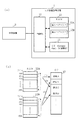
図1は本発明のログ情報取得装置を適用したシステムの構成を示すブロック図である。本システムは、図1に示すように、ログ情報を取得するログ情報取得装置1と、ログ情報取得装置1によりログ情報の取得対象となる対象装置2とからなる。
FIG. 1 is a block diagram showing the configuration of a system to which a log information acquisition apparatus of the present invention is applied. As shown in FIG. 1, the present system includes a log
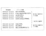
ここで、対象装置2は、一例としてISDN回線に接続されるような電話装置である。ログ情報取得装置は、利用者がこのような電話装置を利用して相手先に発信して通話を行った際に、その装置内で発生した、図2に示すような、「SETUP],「CALL−PROC」などのイベント情報をそのイベント情報の発生時刻情報とともに、ログ情報として取得するものである。 Here, the target apparatus 2 is a telephone apparatus connected to an ISDN line as an example. As shown in FIG. 2, when the user makes a call by making a call to the other party using such a telephone device, the log information acquisition device, as shown in FIG. 2, “SETUP”, “ Event information such as “CALL-PROC” is acquired as log information together with the occurrence time information of the event information.
ここで、ログ情報取得装置1は、図1(a)に示すように、対象装置2からログ情報を取得する制御部11と、制御部11により取得されたログ情報を一時的に格納するRAM12と、RAM12に格納されているログ情報が必要に応じて格納されるCF(compact Flash:記憶媒体)13とからなる。
Here, as illustrated in FIG. 1A, the log
RAM12には、ログ情報を格納するための第1ログエリア12Aと第2ログエリア12Bとが設けられ、第1ログエリア12Aと第2ログエリア12Bは共に、リングバッファとして用いられる。すなわち、第1ログエリア12Aの場合、図1(b)に示すように、アドレスが先頭の100番地から最後の1XX番地まで割り当てられているとすると、ログ情報が先頭の100番地から順次格納されて最後の1XX番地まで格納されると、再び先頭の100番地から順次格納されるものとなっている。また、第2ログエリア12Bの場合についても、アドレスが先頭の200番地から最後の2XX番地まで割り当てられているとすると、ログ情報が先頭の200番地から順次格納されて最後の2XX番地まで格納されると、再び先頭の200番地から順次格納されるものとなっている。
The
このようなログ情報取得装置1では、制御部11が対象装置2からログ情報を取得すると、まずRAM12の第1ログエリア12Aに格納し、こうしたログ情報の第1ログエリア12Aへの格納中に、例えばその第1ログエリアが満杯になると、第2ログエリア12Bへの切り替えを行い、以降、対象装置2から取得したログ情報を、第2ログエリア12Bに格納するように制御する。この場合、第1ログエリア12Aのログ情報については、図1(b)のように、CF13の領域Aに格納しバックアップする。
In such a log
その後、ログ情報の第2ログエリア12Bへの格納中に、その第2ログエリア12Bが満杯になると、今度は第1ログエリア12Aへの切り替えを行い、それ以降、対象装置2から取得したログ情報を、第1ログエリア12Aに格納するように制御する。この場合、第2ログエリア12Bのログ情報については、図1(b)のように、CF13の領域Bに格納しバックアップする。
Thereafter, when the
このように、一方のログエリアのログ情報が満杯になると他方のログエリアに切り替えてそのログエリアにログ情報を格納するように制御する。ここで、ログ情報が満杯になった上記一方のログエリアのログ情報については、後述するように他方のログエリアにログ情報が格納中に、CF13に格納してバックアップするようにしたので、一方のログエリアのログ情報のバックアップ中に新たなログ情報が発生してもこれを取得して他方のログエリアに格納できる。
In this way, when the log information in one log area becomes full, control is performed to switch to the other log area and store the log information in that log area. Here, the log information of the one log area where the log information is full is backed up by storing it in the
(第1の実施の形態)
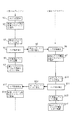
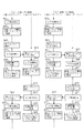
次に、ログ情報取得装置1の第1の動作について、図3の動作説明図にしたがって説明する。
ログ情報取得装置1の制御部11は、対象装置2からのログ情報の取得を開始する(ステップS1)。そして、取得したログ情報をまず第1ログエリア12Aに格納する(ステップS2)。このようにして、第1ログエリア12Aには順次ログ情報が格納される。ここで、対象装置2で発生しその対象装置2から取得したログ情報がログ情報取得装置1内に予め設定されたイベント情報(例えば、図2に示す「CALL−PROC」などのイベント情報)と一致した場合は、設定したイベントの発生(ステップS3)となり、この場合制御部11は、前記のイベント情報をログ情報として第1ログエリア12Aに格納したうえ、第1ログエリア12Aへのログ情報の格納停止(ステップS4)を行って、第2ログエリア12Bに切り替える(ステップS5)。そして、対象装置2から以降取得されたログ情報をその第2ログエリア12Bに順次格納する(ステップS6,S7)。
(First embodiment)
Next, the first operation of the log
The
ログ情報取得装置1の制御部11は、一方のエリアである第2ログエリア12Bにこうしたログ情報を格納しているときに、対象装置2がアイドル状態になったことを検出すると(ステップS8)、ログ情報の格納が停止されている他方のエリアである第1ログエリア12Aのログ情報をCF13に格納することにより、その第1ログエリア12Aのログ情報をバックアップする(ステップS9)。
When the
ここで、第2ログエリア12Bにログ情報を格納しているときに、対象装置2から取得したログ情報がログ情報取得装置1内に予め設定されたイベント情報と一致した場合は、設定したイベントの発生(ステップS10)となり、この場合制御部11は、前記のイベント情報を第2ログエリア12Bに格納したうえ、第2ログエリア12Bへの取得ログ情報の格納停止(ステップS11)を行って、第1ログエリア12Aに切り替える(ステップS12)。そして、以降対象装置2から取得されたログ情報をその第1ログエリア12Aに順次格納する(ステップS13,S14)。
Here, when log information is stored in the
なお、こうした第1ログエリア12Aへのログ情報を格納しているときに、対象装置2がアイドル状態になったことを検出すると(ステップS15)、制御部11は第2ログエリア12Bのログ情報をCF13に格納することにより、その第2ログエリア12Bのログ情報をバックアップする(ステップS16)。
When storing the log information in the
このように、第1の実施の形態では、一方のログエリアにログ情報を格納中に、対象装置2から取得したログ情報が予め設定されたイベント情報と一致する場合は、他方のログエリアに切り替えて引き続きそのログエリアにログ情報を格納するとともに、上記一方のログエリアのログ情報については、他方のログエリアにログ情報が格納可能状態にあるときに対象装置2がアイドル状態になるとCF13に格納してバックアップするようにしたので、対象装置2の或るイベント以前の例えば動作確認を行うような場合、そのイベント情報を設定しておけば、そのイベント以前のログ情報が取得され、したがって、そのログ情報をもとに動作確認が可能になるとともに、ログ情報のバックアップ中にも新たなログ情報を取得しログエリアに格納できる。
As described above, in the first embodiment, when log information is stored in one log area and the log information acquired from the target device 2 matches the preset event information, the log information is stored in the other log area. The log information is continuously stored in the log area after switching, and the log information of the one log area is stored in the
(第2の実施の形態)
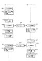
次に、ログ情報取得装置1の第2の動作について、図4の動作説明図にしたがって説明する。
ログ情報取得装置1の制御部11は、対象装置2からのログ情報の取得を開始する(ステップS21)。そして、取得したログ情報をまず第1ログエリア12Aに格納する(ステップS22)。こうした第1ログエリア12Aへのログ情報の格納中に、対象装置2でエラーが発生しその対象装置2から取得したログ情報がエラーイベントである場合は、エラーイベントの発生(ステップS23)となり、この場合制御部11は、そのエラーイベント情報を第1ログエリア12Aに格納したうえ、第1ログエリア12Aへのログ情報の格納停止(ステップS24)を行って、第2ログエリア12Bに切り替える(ステップS25)。そして、対象装置2から以降取得されたログ情報をその第2ログエリア12Bに順次格納する(ステップS26,S27)。
(Second Embodiment)
Next, the second operation of the log
The
ログ情報取得装置1の制御部11は、第2ログエリア12Bにこうしたログ情報を格納しているときに、対象装置2がアイドル状態になったことを検出すると(ステップS28)、第1ログエリア12Aのログ情報をCF13に格納することにより、その第1ログエリア12Aのログ情報をバックアップする(ステップS29)。
When the
ここで、第2ログエリア12Bにログ情報を格納しているときに、所定時間が経過すると(ステップS30)、制御部11は第2ログエリア12Bへの取得ログ情報の格納停止(ステップS31)を行って、第1ログエリア12Aに切り替える(ステップS32)。そして、対象装置2から以降取得したログ情報をその第1ログエリア12Aに順次格納する(ステップS33,S34)。
Here, when log information is stored in the
なお、こうした第1ログエリア12Aへのログ情報を格納しているときに、対象装置2がアイドル状態になったことを検出すると(ステップS35)、制御部11は第2ログエリア12Bのログ情報をCF13に格納することにより、その第2ログエリア12Bのログ情報をバックアップする(ステップS36)。
When storing the log information in the
以上の説明は、第1ログエリア12Aにログ情報を格納中に、対象装置2から取得したログ情報がエラーイベント情報である場合は、第2ログエリア12Bに切り替えてそのログエリアにログ情報を格納し、所定時間が経過すると、第1ログエリア12Aに切り替えてそのログエリアにログ情報を格納するようにしているが、第2ログエリア12Bにログ情報を格納中に、対象装置2から取得したログ情報がエラーイベント情報である場合は、第1ログエリア12Aに切り替えてそのログエリアにログ情報を格納し、所定時間が経過すると、第2ログエリア12Bに切り替えてそのログエリアにログ情報を格納するようにしてもよい。
In the above description, when log information acquired from the target device 2 is error event information while log information is stored in the
このように、第2の実施の形態では、一方のログエリアにログ情報を格納中に、対象装置2から取得したログ情報がエラーイベント情報である場合は、他方のログエリアに切り替えて引き続きそのログエリアにログ情報を格納するとともに、所定時間が経過すると、以降取得したログ情報は上記一方のログエリアに格納し、さらに一方のログエリアのログ情報については他方のログエリアにログ情報を格納しているときに、対象装置2がアイドル状態になるとCF13に格納してバックアップするようにしたので、対象装置2でエラーが発生した場合、そのエラー前のログ情報とエラー後の所定時間内のログ情報が取得され、これにより、そのエラーがどのような原因で生じたかを確認できるとともに、ログ情報のバックアップ中にも新たなログ情報を取得しログエリアに格納できる。
As described above, in the second embodiment, when log information acquired from the target device 2 is error event information while log information is stored in one log area, the log information is continuously switched to the other log area. Log information is stored in the log area, and after a predetermined time has elapsed, the acquired log information is stored in one of the log areas, and the log information of one log area is stored in the other log area. When the target device 2 becomes idle, the data is stored in the
(第3の実施の形態)
次に、ログ情報取得装置1の第3の動作について、図5の動作説明図にしたがって説明する。ここで、図5(a)は対象装置2の故障原因を特定するために最低限必要となるログ情報(必須ログ情報)を取得する場合の例であり、また、図5(b)は対象装置2から詳細なログ情報を取得する場合の例である。まず図5(a)に示す動作から説明する。
(Third embodiment)
Next, the third operation of the log
ログ情報取得装置1の制御部11は、対象装置2からのログ情報(必須ログ情報)の取得を開始する(ステップS41)。そして、取得したログ情報をまず第1ログエリア12Aに格納する(ステップS42)。このようにして、第1ログエリア12Aには順次ログ情報が格納される。ここで、第1ログエリア12Aがログ情報で満杯になると(ステップS43)、制御部11は第1ログエリア12Aへのログ情報の格納停止(ステップS44)を行って、第2ログエリア12Bに切り替える(ステップS45)。そして、対象装置2から以降取得されたログ情報をその第2ログエリア12Bに順次格納する(ステップS46,S47)。
The
ログ情報取得装置1の制御部11は、第2ログエリア12Bにこうしたログ情報を格納しているときに、対象装置2がアイドル状態になったことを検出すると(ステップS48)、第1ログエリア12Aのログ情報をCF13に格納することにより、その第1ログエリア12Aのログ情報をバックアップする(ステップS49)。
When the
ここで、第2ログエリア12Bにログ情報を格納しているときに、第2ログエリア12Bがログ情報で満杯になると(ステップS50)、制御部11は第2ログエリア12Bへのログ情報の格納停止(ステップS51)を行って、第1ログエリア12Aに切り替える(ステップS52)。そして、対象装置2から以降取得されたログ情報をその第1ログエリア12Aに順次格納する(ステップS53,S54)。
Here, when the log information is stored in the
なお、こうした第1ログエリア12Aへのログ情報を格納しているときに、対象装置2がアイドル状態になったことを検出すると(ステップS55)、制御部11は第2ログエリア12Bのログ情報をCF13に格納することにより、その第2ログエリア12Bのログ情報をバックアップする(ステップS56)。
When storing the log information in the
このように、一方のログエリアにログ情報を格納中に、その一方のログエリアが満杯になると他方のログエリアに切り替えて引き続きそのログエリアにログ情報を格納するとともに、上記一方のログエリアのログ情報については他方のログエリアにログ情報を格納しているときに対象装置2がアイドル状態になるとCF13に格納してバックアップするようにしたので、対象装置2の故障原因を特定するために最低限必要となる必須ログ情報を漏れなく取得することができ、これにより、対象装置2の故障原因を容易に特定できる。また、ログ情報のバックアップ中にも新たなログ情報を取得しログエリアに格納できる。
In this way, when log information is stored in one log area, when that one log area becomes full, the log area is switched to the other log area and the log information is continuously stored in that log area. The log information is stored in the
次に、図5(b)の動作説明図にしたがい、対象装置2から詳細ログ情報を取得する場合の動作を説明する。
ログ情報取得装置1の制御部11は、対象装置2からの詳細ログ情報の取得を開始する(ステップS61)。そして、取得したログ情報をまず第1ログエリア12Aに格納する(ステップS62)。このようにして、第1ログエリア12Aには順次詳細ログ情報が格納される。ここで、対象装置2で発生しその対象装置2から取得したログ情報がログ情報取得装置1内に予め設定されたイベント情報と一致した場合は、設定したイベントの発生(ステップS63)となり、この場合制御部11は、前記のイベント情報をログ情報として第1ログエリア12Aに格納したうえ、第1ログエリア12Aへのログ情報の格納停止(ステップS64)を行って、第2ログエリア12Bに切り替える(ステップS65)。そして、対象装置2から以降取得されたログ情報をその第2ログエリア12Bに順次格納する(ステップS66,S67)。
Next, the operation for acquiring detailed log information from the target apparatus 2 will be described with reference to the operation explanatory diagram of FIG.
The
ログ情報取得装置1の制御部11は、第2ログエリア12Bにこうしたログ情報を格納しているときに、対象装置2がアイドル状態になったことを検出すると(ステップS68)、第1ログエリア12Aのログ情報をCF13に格納することにより、その第1ログエリア12Aのログ情報をバックアップする(ステップS69)。
When the
ここで、第2ログエリア12Bにログ情報を格納しているときに、対象装置2から取得したログ情報がログ情報取得装置1内に予め設定されたイベント情報と一致した場合は、設定したイベントの発生(ステップS70)となり、この場合制御部11は、前記のイベント情報を第2ログエリア12Bに格納したうえ、第2ログエリア12Bへの取得ログ情報の格納停止(ステップS71)を行って、第1ログエリア12Aに切り替える(ステップS72)。そして、以降対象装置2から取得されたログ情報をその第1ログエリア12Aに順次格納する(ステップS73,S74)。
Here, when log information is stored in the
なお、こうした第1ログエリア12Aへのログ情報を格納しているときに、対象装置2がアイドル状態になったことを検出すると(ステップS75)、制御部11は第2ログエリア12Bのログ情報をCF13に格納することにより、その第2ログエリア12Bのログ情報をバックアップする(ステップS76)。
When storing the log information in the
このように、一方のログエリアに詳細ログ情報を格納中に、対象装置2から取得した詳細ログ情報が予め設定されたイベント情報と一致する場合は、他方のログエリアに切り替えて引き続きそのログエリアに詳細ログ情報を格納するとともに、上記一方のログエリアの詳細ログ情報については他方のログエリアにログ情報を格納しているときに対象装置2がアイドル状態になるとCF13に格納してバックアップするようにしたので、対象装置2の或るイベント以前の例えば動作確認を行うような場合、そのイベント情報を設定しておけば、そのイベント以前の詳細ログ情報が取得され、したがって、その詳細ログ情報をもとに対象装置2の詳細な動作確認が可能になるとともに、詳細ログ情報のバックアップ中にも新たなログ情報を取得しログエリアに格納できる。
As described above, when the detailed log information acquired from the target apparatus 2 matches the preset event information while storing the detailed log information in one log area, the log area is continuously switched to the other log area. And the detailed log information of the one log area is stored in the
以上の説明は、第1ログエリア12Aに詳細ログ情報を格納中に、対象装置2から取得した詳細ログ情報が予め設定されたイベント情報である場合は、第2ログエリア12Bに切り替えてそのログエリアに詳細ログ情報を格納するようにしているが、第2の実施の形態のように、第1ログエリア12Aに詳細ログ情報を格納中に、対象装置2からエラーイベント情報を取得すると、第2ログエリア12Bに切り替えてそのログエリアに詳細ログ情報を所定時間格納し、所定時間が経過すると、第1ログエリア12Aに切り替えてそのログエリアに詳細ログ情報を格納するように構成することもできる。この場合、第2ログエリア12Bに詳細ログ情報を格納中に、対象装置2からエラーイベント情報を取得すると、第1ログエリア12Aに切り替えてそのログエリアに詳細ログ情報を格納し、所定時間が経過すると、第2ログエリア12Bに切り替えてそのログエリアに詳細ログ情報を格納するようにしてもよい。
In the above explanation, when the detailed log information acquired from the target device 2 is the preset event information while the detailed log information is stored in the
なお、第3の実施の形態では、第1ログエリアと第2ログエリアに必須ログ情報を格納した例(図5(a))と、第1ログエリアと第2ログエリアに詳細ログ情報を格納した例(図5(b))について説明したが、図5(a)に示す第1ログエリアと第2ログエリアを、広義の第1のエリアとし、図5(b)に示す第1ログエリアと第2ログエリアを、広義の第2のエリアとすれば、前記第1のエリアは必須ログ情報を格納するためのエリア、前記第2のエリアは詳細ログ情報を格納するためのエリアということができる。すなわち、ログエリアを、必須ログ情報を格納する前記第1のエリアと、詳細ログ情報を格納する前記第2のエリアとに分けて使用することができる。 In the third embodiment, the essential log information is stored in the first log area and the second log area (FIG. 5A), and the detailed log information is stored in the first log area and the second log area. Although the stored example (FIG. 5B) has been described, the first log area and the second log area shown in FIG. 5A are defined as first areas in a broad sense, and the first log area shown in FIG. If the log area and the second log area are second areas in a broad sense, the first area is an area for storing essential log information, and the second area is an area for storing detailed log information. It can be said. That is, the log area can be divided into the first area for storing essential log information and the second area for storing detailed log information.
そして、対象装置2から取得したログ情報についてそのログ情報が必須ログ情報か或いは詳細ログ情報かを制御部11が判別し、必須ログ情報の場合は、前記第1のエリア内の第1領域(即ち、図5(a)の第1ログエリア)に格納しその領域が満杯になると、前記第1のエリア内の第2領域(即ち、図5(a)の第2ログエリア)に切り替えて以降の必須ログ情報はその切り替えられた領域に格納する。また、詳細ログ情報の場合は前記第2のエリア内の第1領域(即ち、図5(b)の第1ログエリア)に格納し、その領域に格納中に予め設定しておいたイベントを検出すると、前記第2のエリア内の第2領域(即ち、図5(b)の第2ログエリア)に切り替えて以降の詳細ログ情報はその切り替えられた領域に格納する。なお、前記第2のエリア内の例えば第1領域に詳細ログ情報を格納中に、対象装置2からエラーイベント情報を取得すると、第2領域に切り替えてその第2領域に詳細ログ情報を所定時間分格納し、その所定時間が経過すると第2領域に切り替えてその領域に詳細ログ情報を格納することもできる。
Then, the
なお、本実施の形態では、一方のログエリアにログ情報を格納中に、その一方のログエリアが満杯になる条件など所定の条件に応じて、他方のログエリアに切り替えて引き続きそのログエリアにログ情報を格納するとともに、上記一方のログエリアのログ情報については他方のログエリアにログ情報を格納しているときに対象装置2がアイドル状態になるタイミングでCF13にバックアップするように構成しているが、上記一方のログエリアのログ情報のバックアップについては、上記以外のタイミングでも良く、要は上記一方のログエリアに再びログ情報が格納されるまでにそのログエリアのログ情報がバックアップできるようなタイミングであれば良い。
In the present embodiment, while log information is being stored in one log area, the log area is switched to the other log area according to a predetermined condition such as a condition that the other log area is full. The log information is stored, and the log information of the one log area is configured to be backed up to the
1…ログ情報取得装置、2…対象装置、11…制御部、12…RAM、12A…第1ログエリア、12B…第2ログエリア、13…CF(記憶媒体)。
DESCRIPTION OF
Claims (6)
前記発生装置から取得した前記ログ情報を複数のログエリアのいずれかのログエリアに格納する第1のログ情報格納手段と、
所定の条件に応じて、他のログエリアに切り替えるログエリア切替手段と、
前記ログエリア切替手段により切り替えられたログエリアにログ情報を格納する第2のログ情報格納手段と、
前記第1のログ情報格納手段により格納されたログ情報を記憶媒体に転送しバックアップするバックアップ手段と
を有することを特徴とするログ情報の取得装置。 In a log information acquisition device that acquires the log information from a generation device that generates log information,
First log information storage means for storing the log information acquired from the generator in any one of a plurality of log areas;
Log area switching means for switching to another log area according to a predetermined condition;
Second log information storage means for storing log information in the log area switched by the log area switching means;
A log information acquisition apparatus comprising: backup means for transferring and backing up the log information stored by the first log information storage means to a storage medium.
前記ログエリア切替手段は、前記所定の条件が、前記発生装置から取得したログ情報が予め設定されたイベント情報と一致したことを示す条件の場合に、他のログエリアに切り替えることを特徴とするログ情報の取得装置。 In claim 1,
The log area switching means switches to another log area when the predetermined condition is a condition indicating that the log information acquired from the generation device matches the preset event information. Log information acquisition device.
前記ログエリア切替手段は、前記所定の条件を検出した後の所定時間経過後に切り替えることを特徴とするログ情報の取得装置。 In claim 1,
The log information switching device is characterized in that the log area switching means switches after a predetermined time has elapsed after detecting the predetermined condition.
前記ログエリア切替手段は、前記所定の条件が、前記第1のログ情報格納手段の処理に基づいてログエリアが満杯になることを示す条件の場合に、他のログエリアに切り替えることを特徴とするログ情報の取得装置。 In claim 1,
The log area switching means switches to another log area when the predetermined condition is a condition indicating that the log area is full based on the processing of the first log information storage means. Log information acquisition device.
前記ログエリアはリングバッファにより構成されることを特徴とするログ情報の取得装置。 In any of claims 1 to 4,
An apparatus for acquiring log information, wherein the log area includes a ring buffer.
前記発生装置から取得した前記ログ情報が必須ログ情報か或いは詳細ログ情報かを判別する判別手段と、
前記判別手段により前記必須ログ情報と判別された場合はこの必須ログ情報を複数の領域のいずれかの領域に格納する第1のログ情報格納手段と、
前記第1のログ情報格納手段の処理続行中にログ情報を格納している領域が満杯になると、他の領域に切り替える第1の切替手段と、
前記第1の切替手段により切り替えられた領域に必須ログ情報を格納する第2のログ情報格納手段と、
前記第1のログ情報格納手段により格納された必須ログ情報を記憶媒体に転送しバックアップする第1のバックアップ手段と、
前記判別手段により前記詳細ログ情報と判別された場合はこの詳細ログ情報を格納する第3のログ情報格納手段と、
前記第3のログ情報格納手段の処理実行に基づき第1及び第2の領域のいずれか一方の領域が使用中に、所定の条件に応じて、第1及び第2の領域のいずれか他方の領域に切り替える第2の切替手段と、
前記第2の切替手段により切り替えられた領域に詳細ログ情報を格納する第4のログ情報格納手段と、
前記第4のログ情報格納手段の処理実行に基づき第1及び第2の領域のいずれか他方の領域が使用されているときに、第1及び第2の領域のいずれか一方の領域に格納されている前記詳細ログ情報を記憶媒体に転送しバックアップする第2のバックアップ手段と
を有することを特徴とするログ情報の取得装置。
In a log information acquisition device that acquires the log information from a generation device that generates log information,
Determining means for determining whether the log information acquired from the generating device is essential log information or detailed log information;
First log information storage means for storing the required log information in any one of a plurality of areas when the required log information is determined by the determination means;
A first switching means for switching to another area when the area storing the log information becomes full while the processing of the first log information storage means is continued;
Second log information storage means for storing essential log information in the area switched by the first switching means;
First backup means for transferring and backing up the essential log information stored by the first log information storage means to a storage medium;
A third log information storage unit for storing the detailed log information when the detailed log information is determined by the determination unit;
Based on the execution of the process of the third log information storage means, either one of the first and second areas is in use, and one of the first and second areas is selected according to a predetermined condition. A second switching means for switching to the area;
Fourth log information storage means for storing detailed log information in the area switched by the second switching means;
When one of the first and second areas is used based on the execution of the process of the fourth log information storage means, it is stored in one of the first and second areas. And a second backup means for transferring and backing up the detailed log information to a storage medium.
Priority Applications (1)
| Application Number | Priority Date | Filing Date | Title |
|---|---|---|---|
| JP2004103384A JP2005292932A (en) | 2004-03-31 | 2004-03-31 | Device for acquiring log information |
Applications Claiming Priority (1)
| Application Number | Priority Date | Filing Date | Title |
|---|---|---|---|
| JP2004103384A JP2005292932A (en) | 2004-03-31 | 2004-03-31 | Device for acquiring log information |
Publications (1)
| Publication Number | Publication Date |
|---|---|
| JP2005292932A true JP2005292932A (en) | 2005-10-20 |
Family
ID=35325834
Family Applications (1)
| Application Number | Title | Priority Date | Filing Date |
|---|---|---|---|
| JP2004103384A Pending JP2005292932A (en) | 2004-03-31 | 2004-03-31 | Device for acquiring log information |
Country Status (1)
| Country | Link |
|---|---|
| JP (1) | JP2005292932A (en) |
Cited By (6)
| Publication number | Priority date | Publication date | Assignee | Title |
|---|---|---|---|---|
| JP2007265002A (en) * | 2006-03-28 | 2007-10-11 | Hitachi Ltd | Storage system, power supply control method thereof, storage apparatus, and data processing method |
| JP2008146474A (en) * | 2006-12-12 | 2008-06-26 | Oki Data Corp | Information processing device |
| WO2009031210A1 (en) * | 2007-09-05 | 2009-03-12 | Fujitsu Limited | Information processor, method and program for controlling information processor |
| WO2013008281A1 (en) * | 2011-07-08 | 2013-01-17 | 富士通株式会社 | Information processing device, information processing method, and program |
| JP2013206147A (en) * | 2012-03-28 | 2013-10-07 | Yokohama National Univ | Logging device, logging method, and program |
| JP2021114144A (en) * | 2020-01-20 | 2021-08-05 | 株式会社リコー | Information processing equipment, log management methods, and programs |
Citations (14)
| Publication number | Priority date | Publication date | Assignee | Title |
|---|---|---|---|---|
| JPS58112147A (en) * | 1981-12-25 | 1983-07-04 | Fujitsu Ltd | Automatic trace process controlling system |
| JPS6247759A (en) * | 1985-08-26 | 1987-03-02 | Fujitsu Ltd | Automatic line trace processing system |
| JPH01320550A (en) * | 1988-06-22 | 1989-12-26 | Fujitsu Ltd | Tracing system |
| JPH02287653A (en) * | 1989-04-27 | 1990-11-27 | Toshiba Eng Co Ltd | Bus tracer |
| JPH05241891A (en) * | 1992-02-26 | 1993-09-21 | Nec Corp | Tracer circuit |
| JPH05289907A (en) * | 1992-04-14 | 1993-11-05 | Hitachi Ltd | Tracing system |
| JPH05313957A (en) * | 1992-05-11 | 1993-11-26 | Kyushu Nippon Denki Software Kk | Zone-switching system for execution history storing area |
| JPH05324396A (en) * | 1992-05-19 | 1993-12-07 | Fujitsu Ltd | Program run history recording method |
| JPH096651A (en) * | 1995-06-16 | 1997-01-10 | Shikoku Nippon Denki Software Kk | Scsi tracer device |
| JPH1021113A (en) * | 1996-07-03 | 1998-01-23 | Canon Inc | How to debug the debug system |
| JPH11232145A (en) * | 1998-02-13 | 1999-08-27 | Sharp Corp | Log information recording device |
| JP2000057013A (en) * | 1998-08-13 | 2000-02-25 | Nec Corp | Trace information sampling device and mechanically readable recording medium recording program |
| JP2002323959A (en) * | 2001-02-05 | 2002-11-08 | Internatl Business Mach Corp <Ibm> | System and method for non-volatile write cache based on log of magnetic disk controller |
| JP2003076604A (en) * | 2001-09-03 | 2003-03-14 | Nec Access Technica Ltd | Log information collecting system and method for flash memory |
-
2004
- 2004-03-31 JP JP2004103384A patent/JP2005292932A/en active Pending
Patent Citations (14)
| Publication number | Priority date | Publication date | Assignee | Title |
|---|---|---|---|---|
| JPS58112147A (en) * | 1981-12-25 | 1983-07-04 | Fujitsu Ltd | Automatic trace process controlling system |
| JPS6247759A (en) * | 1985-08-26 | 1987-03-02 | Fujitsu Ltd | Automatic line trace processing system |
| JPH01320550A (en) * | 1988-06-22 | 1989-12-26 | Fujitsu Ltd | Tracing system |
| JPH02287653A (en) * | 1989-04-27 | 1990-11-27 | Toshiba Eng Co Ltd | Bus tracer |
| JPH05241891A (en) * | 1992-02-26 | 1993-09-21 | Nec Corp | Tracer circuit |
| JPH05289907A (en) * | 1992-04-14 | 1993-11-05 | Hitachi Ltd | Tracing system |
| JPH05313957A (en) * | 1992-05-11 | 1993-11-26 | Kyushu Nippon Denki Software Kk | Zone-switching system for execution history storing area |
| JPH05324396A (en) * | 1992-05-19 | 1993-12-07 | Fujitsu Ltd | Program run history recording method |
| JPH096651A (en) * | 1995-06-16 | 1997-01-10 | Shikoku Nippon Denki Software Kk | Scsi tracer device |
| JPH1021113A (en) * | 1996-07-03 | 1998-01-23 | Canon Inc | How to debug the debug system |
| JPH11232145A (en) * | 1998-02-13 | 1999-08-27 | Sharp Corp | Log information recording device |
| JP2000057013A (en) * | 1998-08-13 | 2000-02-25 | Nec Corp | Trace information sampling device and mechanically readable recording medium recording program |
| JP2002323959A (en) * | 2001-02-05 | 2002-11-08 | Internatl Business Mach Corp <Ibm> | System and method for non-volatile write cache based on log of magnetic disk controller |
| JP2003076604A (en) * | 2001-09-03 | 2003-03-14 | Nec Access Technica Ltd | Log information collecting system and method for flash memory |
Cited By (8)
| Publication number | Priority date | Publication date | Assignee | Title |
|---|---|---|---|---|
| JP2007265002A (en) * | 2006-03-28 | 2007-10-11 | Hitachi Ltd | Storage system, power supply control method thereof, storage apparatus, and data processing method |
| JP2008146474A (en) * | 2006-12-12 | 2008-06-26 | Oki Data Corp | Information processing device |
| WO2009031210A1 (en) * | 2007-09-05 | 2009-03-12 | Fujitsu Limited | Information processor, method and program for controlling information processor |
| WO2013008281A1 (en) * | 2011-07-08 | 2013-01-17 | 富士通株式会社 | Information processing device, information processing method, and program |
| JPWO2013008281A1 (en) * | 2011-07-08 | 2015-02-23 | 富士通株式会社 | Information processing apparatus, information processing method, and program |
| JP2013206147A (en) * | 2012-03-28 | 2013-10-07 | Yokohama National Univ | Logging device, logging method, and program |
| JP2021114144A (en) * | 2020-01-20 | 2021-08-05 | 株式会社リコー | Information processing equipment, log management methods, and programs |
| JP7396067B2 (en) | 2020-01-20 | 2023-12-12 | 株式会社リコー | Information processing device, log management method, and program |
Similar Documents
| Publication | Publication Date | Title |
|---|---|---|
| CN1016828B (en) | Central control unit and working method for exchange system | |
| JP2004139523A (en) | Information processing apparatus and information processing method | |
| JP2005292932A (en) | Device for acquiring log information | |
| JP3263671B2 (en) | Error detection device | |
| JP2009025971A (en) | Information processor and log data collection system | |
| CN107391036A (en) | The VPD information access method and system of a kind of storage | |
| JPH1097471A (en) | Error correction method and error correction method for memory data | |
| JP2008226177A (en) | Distributed processing program, system and method | |
| JPH04339399A (en) | Relief address analyzing circuit for memory tester | |
| JP2009063455A (en) | Vehicle failure detection device | |
| CN117440088B (en) | Calling method and related equipment | |
| CN120803798B (en) | Troubleshooting methods and electronic devices for storage controllers | |
| JPH04313581A (en) | Elevator monitoring device | |
| JPH11328044A (en) | Method and device for monitoring associative memory | |
| CN111045845B (en) | Data returning method, device, equipment and computer readable storage medium | |
| KR100854823B1 (en) | Error detection apparatus and method of image display equipment | |
| JP2001109030A (en) | Processor provided with error detecting function | |
| JP2001127832A (en) | Protocol analyzer and protocol analyzing method | |
| US20220415117A1 (en) | Method and apparatus for detecting object exchange behavior, electronic device and storage medium | |
| JP3695078B2 (en) | Programmable controller with pulse output instructions | |
| JPH10320324A (en) | Network trace device | |
| KR100560564B1 (en) | Cut-off call processing method in the improved space switch in wired switch | |
| JPH01286028A (en) | Microprogram patching system | |
| CN116347059A (en) | Image processing chip, application processing chip, electronic device and abnormality detection method | |
| JP4454566B2 (en) | Program runaway monitoring circuit and method |
Legal Events
| Date | Code | Title | Description |
|---|---|---|---|
| A621 | Written request for application examination |
Free format text: JAPANESE INTERMEDIATE CODE: A621 Effective date: 20061030 |
|
| A977 | Report on retrieval |
Free format text: JAPANESE INTERMEDIATE CODE: A971007 Effective date: 20090220 |
|
| A131 | Notification of reasons for refusal |
Free format text: JAPANESE INTERMEDIATE CODE: A131 Effective date: 20091027 |
|
| A521 | Written amendment |
Free format text: JAPANESE INTERMEDIATE CODE: A523 Effective date: 20091221 |
|
| A131 | Notification of reasons for refusal |
Free format text: JAPANESE INTERMEDIATE CODE: A131 Effective date: 20100302 |
|
| A521 | Written amendment |
Free format text: JAPANESE INTERMEDIATE CODE: A523 Effective date: 20100428 |
|
| A02 | Decision of refusal |
Free format text: JAPANESE INTERMEDIATE CODE: A02 Effective date: 20101214 |