JP2005292707A - Display device - Google Patents
Display device Download PDFInfo
- Publication number
- JP2005292707A JP2005292707A JP2004111088A JP2004111088A JP2005292707A JP 2005292707 A JP2005292707 A JP 2005292707A JP 2004111088 A JP2004111088 A JP 2004111088A JP 2004111088 A JP2004111088 A JP 2004111088A JP 2005292707 A JP2005292707 A JP 2005292707A
- Authority
- JP
- Japan
- Prior art keywords
- unit
- reproduction
- playback
- time
- sleep timer
- Prior art date
- Legal status (The legal status is an assumption and is not a legal conclusion. Google has not performed a legal analysis and makes no representation as to the accuracy of the status listed.)
- Withdrawn
Links
- 230000006870 function Effects 0.000 claims abstract description 16
- 238000001816 cooling Methods 0.000 claims description 18
- 230000008929 regeneration Effects 0.000 claims description 9
- 238000011069 regeneration method Methods 0.000 claims description 9
- 230000004044 response Effects 0.000 claims description 3
- 239000004973 liquid crystal related substance Substances 0.000 abstract description 21
- 238000000034 method Methods 0.000 description 34
- 230000008569 process Effects 0.000 description 32
- 238000012545 processing Methods 0.000 description 27
- 230000004048 modification Effects 0.000 description 8
- 238000012986 modification Methods 0.000 description 8
- 238000010586 diagram Methods 0.000 description 3
- 239000000539 dimer Substances 0.000 description 3
- 238000006243 chemical reaction Methods 0.000 description 2
- 230000006835 compression Effects 0.000 description 2
- 238000007906 compression Methods 0.000 description 2
- 238000012937 correction Methods 0.000 description 2
- 230000006866 deterioration Effects 0.000 description 2
- 238000003702 image correction Methods 0.000 description 2
- 238000012423 maintenance Methods 0.000 description 2
- VYPSYNLAJGMNEJ-UHFFFAOYSA-N Silicium dioxide Chemical compound O=[Si]=O VYPSYNLAJGMNEJ-UHFFFAOYSA-N 0.000 description 1
- 230000008859 change Effects 0.000 description 1
- 238000006073 displacement reaction Methods 0.000 description 1
- 230000000694 effects Effects 0.000 description 1
- 230000001678 irradiating effect Effects 0.000 description 1
- 238000012538 light obscuration Methods 0.000 description 1
- QSHDDOUJBYECFT-UHFFFAOYSA-N mercury Chemical compound [Hg] QSHDDOUJBYECFT-UHFFFAOYSA-N 0.000 description 1
- 229910052753 mercury Inorganic materials 0.000 description 1
- 230000003287 optical effect Effects 0.000 description 1
- 238000003825 pressing Methods 0.000 description 1
- 230000002250 progressing effect Effects 0.000 description 1
- 230000000630 rising effect Effects 0.000 description 1
Images
Landscapes
- Projection Apparatus (AREA)
- Liquid Crystal Display Device Control (AREA)
- Television Signal Processing For Recording (AREA)
- Control Of Indicators Other Than Cathode Ray Tubes (AREA)
Abstract
【課題】 記憶媒体を再生する画像再生部と再生された画像を表示する表示部とが一体と
なった表示装置のスリープタイマ機能に関係する再生動作の利便性を向上させる。
【解決手段】 液晶プロジェクタ1は、DVD7に記憶されている画像を再生する再生部
2と、再生部2で再生された画像を投写する投写部3を備え、設定時間が経過することで
再生動作及び投写を停止するスリープタイマ機能を有し、スリープタイマの設定時間の経
過により再生部2の再生動作を停止し、再生部2の停止と共に停止するDVD7の停止位
置情報を再生制御部23のメモリ26に記憶し、再生部2は停止位置情報に対応する位置
から所定の再生動作時間分だけ後戻りした位置から再生動作を開始する。
【選択図】 図1
PROBLEM TO BE SOLVED: To improve convenience of a reproduction operation related to a sleep timer function of a display device in which an image reproduction unit for reproducing a storage medium and a display unit for displaying the reproduced image are integrated.
A liquid crystal projector includes a reproduction unit that reproduces an image stored in a DVD and a projection unit that projects an image reproduced by the reproduction unit, and performs a reproduction operation when a set time elapses. And a sleep timer function for stopping projection, the playback operation of the playback unit 2 is stopped when the set time of the sleep timer elapses, and the stop position information of the DVD 7 that stops together with the stop of the playback unit 2 is stored in the memory of the playback control unit 23 26, the playback unit 2 starts the playback operation from a position backed by a predetermined playback operation time from the position corresponding to the stop position information.
[Selection] Figure 1
Description
本発明は、スリープタイマ機能を備え、記憶媒体(記録媒体)を再生する画像再生部と
、再生された画像を表示する表示部とを備えた表示装置に関する。
The present invention relates to a display device that has a sleep timer function and includes an image reproduction unit that reproduces a storage medium (recording medium) and a display unit that displays the reproduced image.
近年、各種ニーズに応じて多くの記憶媒体が開発され、データ量が多い動画像を記憶再
生する記憶媒体としては、例えばCD(Compact Disc)やDVD(Digital Versatile Di
sc)が多く用いられている。特に、長編の動画像及び音声データを再生できるDVDを使
用した再生装置の普及が急速に進んでいる。一方、再生装置の画像表示装置として、透過
型あるいは反射型の光変調作用を有する表示素子、およびこの表示素子に光を照射する放
電式の光源とから構成され、スクリーンに画像を投写する投写型表示装置、いわゆるプロ
ジェクタが広く知られている。
In recent years, many storage media have been developed according to various needs, and examples of storage media for storing and reproducing moving images having a large amount of data include CD (Compact Disc) and DVD (Digital Versatile Di).
sc) is often used. In particular, the spread of a playback apparatus using a DVD capable of playing back a long moving image and audio data is rapidly progressing. On the other hand, as an image display device of a reproducing apparatus, a projection type that is composed of a transmissive or reflective light-modulating display element and a discharge-type light source that irradiates light to the display element, and projects an image on a screen Display devices, so-called projectors, are widely known.
こうした再生装置において、利便性を考慮したさまざまな機能が提案されている。例え
ば、設定されたスリープタイマ時間をカウントするタイマ手段と、表示手段と、表示手段
の明るさを変えるディマー手段と、タイマ手段のカウント値に応じて表示手段の明るさが
変わるようにディマー手段を制御する制御手段とを備え、スリープタイマの残り時間を確
認し易くしたスリープタイマ機能を有する電子機器が知られている(例えば、特許文献1
参照)。
In such a playback apparatus, various functions that take convenience into account have been proposed. For example, timer means for counting the set sleep timer time, display means, dimmer means for changing the brightness of the display means, and dimmer means for changing the brightness of the display means according to the count value of the timer means. There is known an electronic apparatus having a sleep timer function that includes a control means for controlling and that makes it easy to check the remaining time of the sleep timer (for example, Patent Document 1).
reference).
あるいは、一旦再生が中断された記憶媒体をレジューム再生するときに、再生開始場所
を探す手間を省くことが可能な記憶媒体再生装置が知られている(例えば、特許文献2参
照)。
Alternatively, a storage medium playback device is known that can save the trouble of searching for a playback start location when a storage medium that has once been interrupted is resumed (see, for example, Patent Document 2).
記憶媒体を再生する再生装置には再生された画像を表示する表示装置が必要不可欠であ
り、利便性の面から一体化された装置が提案され始めている。また、表示装置として大型
画面が表示できる一体化された装置が望まれている。
A display device for displaying a reproduced image is indispensable for a reproducing device for reproducing a storage medium, and an integrated device has been proposed from the viewpoint of convenience. Also, an integrated device capable of displaying a large screen as a display device is desired.
そこで、本発明は、記憶媒体を再生する画像再生部と再生された画像を表示する表示部
とが一体となった表示装置において、スリープタイマ機能に関係する再生動作の利便性を
向上させることを目的とする。
Therefore, the present invention improves the convenience of a reproduction operation related to the sleep timer function in a display device in which an image reproduction unit for reproducing a storage medium and a display unit for displaying the reproduced image are integrated. Objective.
上記問題を解決するために、本発明の表示装置は、記憶媒体に記憶されている画像を再
生する再生部と、前記再生部で再生された画像を表示する表示部とを備え、設定時間が経
過することで前記再生部の再生動作及び前記表示部の表示を停止するスリープタイマ機能
を有する表示装置であって、前記記憶媒体の停止位置情報を記憶する記憶手段を備え、前
記スリープタイマの設定時間の経過により前記再生部の再生動作を停止し、前記再生部の
再生動作の停止と共に停止する前記記憶媒体の停止位置情報を前記記憶手段に記憶し、前
記再生部は前記停止位置情報に対応する位置から所定の再生動作時間分だけ後戻りした位
置から再生動作を開始することを特徴とする。
In order to solve the above problem, a display device of the present invention includes a reproduction unit that reproduces an image stored in a storage medium, and a display unit that displays an image reproduced by the reproduction unit. A display device having a sleep timer function for stopping the playback operation of the playback unit and the display of the display unit as it elapses, comprising storage means for storing stop position information of the storage medium, and setting the sleep timer The playback operation of the playback unit is stopped over time, and stop position information of the storage medium that stops when the playback operation of the playback unit stops is stored in the storage unit, and the playback unit corresponds to the stop position information The reproduction operation is started from a position that has been moved back by a predetermined reproduction operation time.
上記によれば、スリープタイマの設定時間を経過し、再生停止した記憶媒体の続きの再
生が開始された時に、停止位置情報に対応する位置から所定の再生動作時間分だけ後戻り
した位置から再生動作を開始するので、例えば映画等のストーリーを思い出すことができ
、例えば映画等の続きを効率良く鑑賞することができる。
According to the above, when the set time of the sleep timer has passed and the subsequent playback of the storage medium that has stopped playback is started, the playback operation is started from the position that is back by the predetermined playback operation time from the position corresponding to the stop position information. Thus, for example, a story such as a movie can be remembered, and for example, a continuation of a movie or the like can be appreciated efficiently.
また、本発明の表示装置は、前記停止位置から後戻りする所定の再生動作時間は、前記
スリープタイマの設定時間の長さに応じた時間に設定されることを特徴とする。
上記によれば、スリープタイマの時間設定が長い程、記憶媒体が後戻りする再生動作時
間が長く設定されるので、再生停止した記憶媒体の続きの再生が開始された時に、例えば
映画等のストーリーを無理なく思い出すことができる。あるいは、見落としてしまい、見
てないかもしれない場面から再生が開始されることもあり、映画等の続きを効率良く鑑賞
することができる。
Further, the display device of the present invention is characterized in that the predetermined playback operation time returning from the stop position is set to a time according to the length of the set time of the sleep timer.
According to the above, as the time setting of the sleep timer is longer, the playback operation time for which the storage medium moves backward is set longer, so that when the playback of the storage medium that has stopped playback is started, a story such as a movie is displayed. I can remember it without difficulty. Or it may be overlooked and playback may be started from a scene that may not be seen, so that the continuation of a movie or the like can be appreciated efficiently.
また、本発明の表示装置は、光源からの光を変調する空間光変調素子を備え、前記停止
位置から後戻りする再生動作時間を入力操作により設定する設定手段を備え、前記再生部
は、前記設定手段に設定された時間と前記光源が所定の輝度値に達する所定の再生動作時
間を加算した時間分、後戻りした位置から再生動作を開始することを特徴とする。
The display device of the present invention includes a spatial light modulation element that modulates light from a light source, and includes a setting unit that sets a reproduction operation time to return from the stop position by an input operation, and the reproduction unit includes the setting The reproduction operation is started from a position that is set back by a time obtained by adding the time set in the means and the predetermined reproduction operation time when the light source reaches a predetermined luminance value.
上記によれば、光源が所定の輝度値に達する所定の再生動作時間を考慮することにより
、再生停止した記憶媒体の続きの再生が開始された時に、画像が投影されない時間帯が少
なく、見てないかもしれない場面を見落としてしまう等を抑止し、映画等の続きを効率良
く鑑賞することができる。
According to the above, by considering the predetermined playback operation time for the light source to reach the predetermined luminance value, when the subsequent playback of the storage medium that has stopped playback is started, there are few times when the image is not projected and It is possible to prevent a scene that may not be present from being overlooked, and to efficiently appreciate the continuation of a movie or the like.
また、表示部は、前記光源に供給する電力値を制御する電力制御部を備え、電力制御部
は前記スリープタイマの残り時間の減少に対応して光源に供給する電力値を低減すること
を特徴とする。
The display unit includes a power control unit that controls a power value supplied to the light source, and the power control unit reduces a power value supplied to the light source in response to a decrease in a remaining time of the sleep timer. And
上記によれば、記憶媒体の再生中に、スリープタイマの残り時間の減少に対応して光源
の電力値を低減することにより、投写される画像が経過時間の段階毎にだんだん暗くなる
ことにより、スリープタイマのおおまかな残り時間を表示される画像で知ることができる
。
According to the above, during reproduction of the storage medium, by reducing the power value of the light source corresponding to the decrease in the remaining time of the sleep timer, the projected image becomes darker at every elapsed time stage, You can know the approximate remaining time of the sleep timer from the displayed image.
また、表示部は、前記光源を冷却する冷却ファンを備え、前記スリープタイマの設定時
間を経過後に、前記再生部の停止、前記光源の消灯、前記冷却ファンの停止の順に電源部
を制御する制御部を有することを特徴とする。
In addition, the display unit includes a cooling fan that cools the light source, and controls the power source unit in order of stopping the reproduction unit, turning off the light source, and stopping the cooling fan after the set time of the sleep timer has elapsed. It has the part.
上記によれば、再生部を停止し光源が消灯した時点では、光源あるいは光源周辺の温度
が、例えば数百℃の高い状態にあるため、冷却ファンを駆動し続けることで光源及び光源
の周辺を冷却して、光源の短寿命化を防止すると共に、高熱に起因する種々の不安全を防
止することができる。
According to the above, when the reproduction unit is stopped and the light source is turned off, the temperature of the light source or the vicinity of the light source is in a high state of, for example, several hundred degrees Celsius. Cooling can prevent the life of the light source from being shortened and can prevent various unsafety caused by high heat.
また、前記再生部の再生動作中に前記投写部の光源が消灯したことを検出すると、前記
光源が消灯した時点の前記記憶媒体の再生位置情報を前記記憶手段に記憶し、前記再生部
は、前記記憶手段に記憶された再生位置情報に対応する位置から、前記光源が所定の輝度
値に達する所定の再生動作時間分だけ後戻りした位置から、前記記憶手段の再生動作を開
始することを特徴とする。
Further, when it is detected that the light source of the projection unit is turned off during the reproduction operation of the reproduction unit, the reproduction unit stores the reproduction position information of the storage medium at the time when the light source is turned off, The reproduction operation of the storage unit is started from a position that has been moved back by a predetermined reproduction operation time when the light source reaches a predetermined luminance value from a position corresponding to the reproduction position information stored in the storage unit. To do.
上記によれば、再生動作中に光源が劣化や破損などにより消灯(不点灯)し光源のメン
テナンス(交換)後に、再生停止した記憶媒体の続きの再生が開始された時に、再生して
いた、例えば映画等のストーリーを思い出すことができ、映画等の続きを効率良く鑑賞す
ることができる。停電による消灯に対応するためには、再生位置情報を記憶させる等の必
要な動作を行うための補助電源を有することが望ましい。
According to the above, the light source was turned off (not lit) due to deterioration or breakage during the playback operation, and after the maintenance (replacement) of the light source, the playback of the storage medium that was stopped playing was started. For example, a story such as a movie can be remembered, and a continuation of the movie can be efficiently viewed. In order to cope with light extinction due to a power failure, it is desirable to have an auxiliary power source for performing necessary operations such as storing reproduction position information.
(第1の実施形態)
以下、本発明を具現化した第1の実施形態を、図1〜図3に基づいて説明する。なお、
本実施形態では、表示装置として空間光変調素子の1種である透過型液晶パネルを用いた
プロジェクタを例に説明する。他の空間光変調素子としては、反射型液晶パネル、DMD
(Digital Micromirror Device:米国TI社の商標)、GLV(Grating Light Valve)等
が挙げられる。
(First embodiment)
Hereinafter, a first embodiment embodying the present invention will be described with reference to FIGS. In addition,
In the present embodiment, a projector using a transmissive liquid crystal panel, which is one type of spatial light modulation element, as a display device will be described as an example. Other spatial light modulators include reflective liquid crystal panels, DMD
(Digital Micromirror Device: Trademark of TI, USA), GLV (Grating Light Valve) and the like.
プロジェクタを構成する再生部の一例として、光ディスクのDVD(Digital Versatil
e Disc)を記憶媒体とするDVD再生装置を用い、表示装置としてのプロジェクタは、よ
り詳しくは、液晶パネルと液晶パネルに光を照射する光源とから構成され、液晶パネルに
よって変調された光をスクリーンに投射して画像を表示する投射型液晶表示装置、いわゆ
る液晶プロジェクタを用いて説明する。
As an example of a playback unit constituting a projector, an optical disc DVD (Digital Versatil
More specifically, a projector as a display device using a DVD playback device using e Disc) as a storage medium is composed of a liquid crystal panel and a light source for irradiating the liquid crystal panel with light, and the light modulated by the liquid crystal panel is screened. A projection-type liquid crystal display device that projects images onto the screen and displays a picture will be described using a so-called liquid crystal projector.
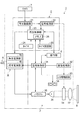
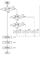
図1は、本実施形態の液晶プロジェクタの概略構成を示すブロック図である。
図1において、液晶プロジェクタ1は、記憶媒体としてのDVD7に記憶されている動
画像等を再生する再生部2と、再生部2において再生された動画像をスクリーン8などに
投写する表示部としての投写部3、電源部4、操作部5等で構成されている。
FIG. 1 is a block diagram showing a schematic configuration of the liquid crystal projector of the present embodiment.
In FIG. 1, a
再生部2は、再生動作部21、信号処理部22、再生制御部23、タイマ24、タイマ
設定部25等で構成され、投写部3は投写制御部31、画像処理部32、LCD駆動回路
33、液晶パネル34、バラスト35、光源としてのランプ36、投写レンズ37、冷却
ファン38等で構成されている。
The
電源部4は、再生電源部4aと投写電源部4bとで構成され、電源制御(電源のオフ制
御)が単独に制御可能に構成されている。なお、再生部2及び投写部3の電源スイッチ(
図示せず)は、電源スイッチが単独にオン、オフ操作される構成であっても良いが、本実
施形態は、1つの電源スイッチのオン操作により再生部2及び投写部3が同時に電源オン
するように構成されている。
操作部5は、例えば各種操作キー(図示せず)が備えられ、各キーの所定の操作により
再生部2および投写部3における各種操作を行うことができる。
The
(Not shown) may be configured such that the power switch is turned on and off independently, but in this embodiment, the
The
再生動作部21は、DVD7の記憶読み取り部であり、DVD7を載せて回転するスピ
ンドルモータ、DVD7に記憶されている記憶を検出するレーザピックアップ、スピンド
ルモータとレーザピックアップを制御するサーボ制御部(いずれも図示せず)等で構成さ
れている。
The
信号処理部22は、再生動作部21において読み取ったアナログ信号を整形してディジ
タル信号化し、定められたルール(例えば、MPEG2と呼ばれる動画圧縮方式)に従っ
て復号化し、復号化された画像データを投写部3の画像処理部32に出力する。また、信
号処理部22は再生動作部21の再生停止時に、DVD7の再生停止位置データを再生制
御部23のメモリ(RAM)26に入力し格納する。この再生制御部23のメモリ26が
記憶媒体(DVD7)の停止位置情報を記憶する記憶手段である。
The
再生制御部23は、スリープタイマ機能、再生戻し処理などの各種処理を実行するCP
U(Central Processing Unit)と、各部を制御する制御プログラムを格納するROMと
処理等を実行する際に各種データを一時的に格納するRAM(合わせてメモリ26として
表示する)等を備え、再生部2全体の動作を制御する。
The
U (Central Processing Unit), ROM that stores a control program that controls each unit, RAM that temporarily stores various data when executing processing, etc. (also displayed as
タイマ24は、所定のスリープタイマ機能及び再生動作部21の再生戻し動作を実行す
るためのタイマであり、タイマ設定部25のキー操作の設定内容に基づきスリープタイマ
機能などが実行される。
タイマ設定部25は、スリープタイマ時間や再生戻し時間を設定する各種操作キーと表
示器が備えられ、各操作キーの所定の操作によりスリープタイマ時間の設定や再生戻し時
間の設定等の操作を行う。なお、タイマ設定部25の詳細は図2に基づいて後述する。
The
The
投写制御部31は、各種処理を実行するCPUと、各種処理等を実行する際にデータを
一時的に格納する、あるいは処理などのアプリケーションプログラムを一時的に展開する
RAMと、各部を制御する制御プログラム等を格納するROMとを備えている。ROMに
記憶された制御プログラムや各種アプリケーションプログラムに基づいて投写部3におけ
る各種動作を実行する。なお、投写制御部31と再生制御部23はバスを介して電気的に
接続され、相互に電源処理信号等の入出力が行われる。
The
画像処理部32は、信号処理部22から入力された動画像データをバッファメモリ(図
示せず)に格納し、フレームレート変換やスケーリング処理、及びブライトネス調整、コ
ントラスト調整、ガンマ補正処理等の画像補正を行い、こうした表示用映像信号をLCD
駆動回路33に入力する。
LCD駆動回路33は、画像処理部32から入力される表示用映像信号を最終的なR,
G,Bの色信号として液晶パネル34に供給する。
The
Input to the
The
This is supplied to the
バラスト35は、投写制御部31からのランプ制御信号に基づいて、ランプ駆動電力を
光源としてのランプ36に出力する。ランプ36は、例えば放電式の超高圧水銀ランプか
らなり、バラスト35から入力されるランプ駆動電力に基づいて点灯駆動する。この投写
制御部31が光源の電力値を制御する制御部である。
冷却ファン38は、ランプ36の冷却用ファンであり、ランプ36の近傍に設けられ、
投写制御部31から冷却ファン制御信号に基づいて駆動し、ランプ36の周囲に冷却風を
送りランプ36の冷却を行う。
The
The cooling
Driven based on the cooling fan control signal from the
次に、再生部2及び投写部3の基本動作について説明する。以下の説明は、インレット
6を介して電源部4に電源電力としての例えば商用交流電源が供給されて、再生部2及び
投写部3の電源がオン状態にあるとして説明する。
Next, basic operations of the
先ず、再生動作部21に記憶媒体としてのDVD7が挿入され、そして操作部5に備え
られた再生キーがオンされると、再生動作部21が回転してDVD7の記憶が読み取られ
る。再生動作部21は読み取ったアナログ信号を信号処理部22に出力する。そして信号
処理部22において、再生動作部21から入力したアナログ信号を整形してディジタル信
号化し、定められたルール(例えば、MPEG2と呼ばれる動画圧縮方式)に従って復号
化し、復号化された画像データを投写部3の画像処理部32に出力する。
First, when the DVD 7 as a storage medium is inserted into the
画像処理部32に入力された動画像データは、バッファメモリに格納され、フレームレ
ート変換やスケーリング処理、及びブライトネス調整、コントラスト調整、ガンマ補正処
理等の画像補正が行われて、表示用映像信号をLCD駆動回路33に入力する。
LCD駆動回路33では、画像処理部32から入力された表示用映像信号を最終的なR
,G,Bの色信号として液晶パネル34に供給され、液晶パネル34が駆動される。
The moving image data input to the
The
, G, B color signals are supplied to the
一方、バラスト35は、投写制御部31からのランプ制御信号に基づいて、ランプ36
の放電を安定的に継続するランプ駆動電力をランプ36に出力し、ランプ36が点灯駆動
される。また、冷却ファン38は、投写制御部31からの冷却ファン制御信号に基づいて
駆動し、ランプ36の周囲に冷却風を送りランプ36の冷却を行う。
On the other hand, the
The lamp driving power for stably continuing the discharge is output to the
そして、ランプ36からの光が液晶パネル34を透過することにより、投写レンズ37
を介して画像がスクリーン8に投影され、DVD7に記憶された例えば映画等の動画像を
再生して鑑賞することができる。
Then, the light from the
The image is projected onto the screen 8 via the video, and a moving image such as a movie stored in the DVD 7 can be reproduced and viewed.
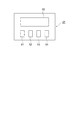
図2は、タイマ設定部25の概略説明図である。図2に示すように、タイマ設定部25
には各種タイマ操作を行う操作キー51〜54と表示器55を備えている。操作キーは、
再生戻し時間をセット(選択)するセットキー51、スリープタイマ時間の設定を行うた
めのセレクトキー52とセットキー53、スリープタイマを開始するスタートキー54が
配置されている。なお、スリープタイマ機能は、スリープタイマを実行(開始)した時点
から一定時間(設定時間)経過すると、自動的に電源が切れる(オフされる)機能であり
、本実施形態では、再生部2と投写部3の電源(電源部4)がオフされる。
FIG. 2 is a schematic explanatory diagram of the
Are provided with
A
セットキー51は、スリープタイマの設定時間が経過し、再生動作部21が再生停止し
して停止したDVD7の再生停止位置から後戻りする再生動作時間(すなわち、再生戻し
時間)を設定するキーであり、プッシュ操作することで予め設定された、例えば10秒、
30秒、1分の3段階の再生戻し時間を順に繰り返しセット(選択)することができる。
セットされた再生戻し時間は、セットキー51を操作してセットし直されるまで保持され
る。このセットキー51が再生動作時間を設定する設定手段である。
The
It is possible to repeatedly set (select) the playback return time in three steps of 30 seconds and 1 minute in order.
The set playback return time is held until it is reset by operating the
セレクトキー52とセットキー53は、スリープタイマの設定時間を設定するための操
作キーであり、セレクトキー52をプッシュ操作することで設定する時間桁と分桁を選択
し、セットキー53をプッシュ操作することで所望のスリープタイマ時間をセットする。
スリープタイマの時間設定は、例えば15分間隔毎に5時間迄の設定が可能である。
表示器55は、こうした各操作キーの操作に対応して再生動作時間やスリープタイマ設
定時間を表示し、スタートキー54がプッシュ操作されたスリープタイマの開始によりス
リープタイマの残り時間を表示する。
The select key 52 and the
The sleep timer can be set up to 5 hours every 15 minutes, for example.
The
次に、スリープタイマ動作について説明する。 Next, the sleep timer operation will be described.
スリープタイマは、タイマ設定部25のセレクトキー52とセットキー53を操作して
スリープタイマの時間設定がされ、表示器55に設定時間が表示される。そして、スター
トキー54がプッシュ操作されることによりスリープタイマが開始する。スタートキー5
4がプッシュ操作されることによりスリープタイマの開始信号が再生制御部23及び投写
制御部31に入力され、再生制御部23を介してタイマ24において時間カウントが行わ
れる。スリープタイマが開始されると、表示器55に表示された設定時間がタイマ24の
時間カウントと共に、設定時間から1分単位に減算表示してスリープタイマの作動終了ま
での時間を表示する。
In the sleep timer, the time of the sleep timer is set by operating the select key 52 and the
4 is pushed, a sleep timer start signal is input to the
そして、再生制御部23は、スリープタイマを開始した時点から設定時間が経過したこ
とをタイマ24からの信号により認知すると、電源部4の再生電源部4aに制御信号を送
り、再生部2の電源がオフするとともに、投写制御部31にスリープタイマの終了信号を
出力する。
Then, when the
一方、スリープタイマの終了信号が入力された投写制御部31では、投写制御部31か
らバラスト35に、ランプ36への供給電力を切断するランプ制御信号が出力され、ラン
プ36が消灯する。そしてランプ36が消灯して所定の時間経過の後に、投写制御部31
から投写電源部4bに制御信号が送られ、投写部3の電源がオフされる。この投写部3の
電源がオフされることにより冷却ファン38の駆動も停止する。
On the other hand, in the
Is sent to the projection
こうした電源制御は、ランプ36が消灯した時点ではランプ36、あるいはランプ36
周辺の温度が、例えば数百℃の高い状態にあるため、冷却ファン38を駆動(回転)し続
けることでランプ36及びランプ36の周辺を冷却して、ランプ36の短寿命化を防止す
る。なお、ランプ36の消灯後に投写部3の電源がオフされる所定の時間は、ランプ36
の温度が一定温度に低下する、例えば3分に設定されている。
Such power control is performed by the
Since the ambient temperature is high, for example, several hundred degrees C., the cooling
Is set to 3 minutes, for example.
次に、再生戻し動作について説明する。再生戻し動作は、DVD7の再生中にスリープ
タイマがセットされ、スリープタイマが終了した後に、再生停止したDVD7の続きの再
生をするために再生部2の再生が開始された場合、あるいはDVD7の再生中に投写部3
のランプ36が、劣化や破損などにより不点灯になり、ランプのメンテナンス(交換)後
に、再生停止したDVD7の続きの再生をするために再生部2の再生が開始された場合に
行われる。
Next, the playback return operation will be described. In the playback return operation, when the sleep timer is set during playback of the DVD 7 and the playback of the
This is done when the reproduction of the
スリープタイマを使用した場合の再生戻し動作は、スリープタイマの時間設定がされた
後に、スタートキー54がプッシュ操作されてスリープタイマが開始され、再生動作部2
1が再生動作中にスリープタイマの設定時間が経過し、タイマ24において時間カウント
が終了すると、再生制御部23は、再生動作部21に再生停止信号を出力する。再生動作
部21では、再生中のDVD7の再生を停止すると共に、再生停止信号を信号処理部22
に入力する。そして、信号処理部22では、停止されたDVD7の再生停止位置データを
再生制御部23に出力し、再生制御部23では、入力された再生停止位置情報をメモリ2
6の所定記憶領域に記憶する。
When the sleep timer is used, the playback return operation is performed after the sleep timer is set, and then the
When the set time of the sleep timer elapses during the
To enter. Then, the
6 is stored in a predetermined storage area.
スリープタイマの終了の後に、再生の開始(再開)の操作が操作部5の所定のキー操作
により行なわれると、再生制御部23は、そのメモリ26に記憶されたDVD7の再生停
止位置データの位置から、セットキー51により設定された再生戻し時間(10秒、30
秒、1分の3段階の内の選択された時間)分、DVD7が後戻りする信号を再生動作部2
1に入力する。再生動作部21は、選択された時間分だけDVD7を後戻りさせて、後戻
りした位置から再生を開始する。
When the operation of starting (resuming) the reproduction is performed by a predetermined key operation of the
Second, the signal that the DVD 7 returns for the time selected in 3 steps of 1 minute)
Enter 1 The
ランプ36が不点灯になった場合の再生戻し動作は、ランプ36の点灯中(再生部2の
再生動作中)に、例えばランプ36を構成する石英ガラスが熱歪により破損等が発生して
不点灯すると、バラスト35においてランプ36を駆動する電力の変位からランプ36の
不点灯を検知し、ランプ36の不点灯信号が投写制御部31に入力される。
When the
そして投写制御部31に入力された不点灯信号を投写制御部31から再生制御部23に
出力し、再生制御部23から再生動作部21に再生停止信号が入力される。再生動作部2
1では、再生中のDVD7の再生を停止すると共に、再生停止信号を信号処理部22に出
力する。そして、信号処理部22では、停止されたDVD7の再生停止位置データを再生
制御部23に出力し、再生制御部23では、入力された再生停止位置情報をメモリ26の
所定記憶領域に記憶される。
Then, the non-lighting signal input to the
1, the reproduction of the DVD 7 being reproduced is stopped and a reproduction stop signal is output to the
以上の再生戻し動作とランプ36の不点灯におけるDVD7の再生停止位置の記憶及び
電源制御について、図3のフローチャートに基づいて説明する。
The above-described playback return operation and storage of the playback stop position of the DVD 7 when the
DVD7の再生停止位置からの再生戻し時間がセットされ、スリープタイマが開始され
た状態にあるDVD7の再生中(投写部3の投写中)、図3のフローチャートで示す処理
が実行される。
During playback of the DVD 7 in the state in which the playback return time from the playback stop position of the DVD 7 is set and the sleep timer is started (during projection of the projection unit 3), the processing shown in the flowchart of FIG. 3 is executed.
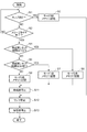
まず、ステップS1では、ランプ36が不点灯(消灯)であるか否かを判定し、不点灯
であるときにはステップS2に移行し、不点灯でないときにはステップS3に移行する。
ステップS2では、モード3をメモリの所定記憶領域に記憶し、次いでステップS12に
移行する。
First, in step S1, it is determined whether or not the
In step S2,
ステップS3では、スリープタイマが終了したか否かを判定し、スリープタイマが終了
してないときには前記ステップS1に戻り、スリープタイマが終了しているときにはステ
ップS4に移行する。
ステップS4では、セットされた再生戻し時間が1分であるか否かを判定し、セットさ
れた再生戻し時間が1分である場合はステップS5に移行して、モード2をメモリの所定
記憶領域に記憶し、次いでステップS11に移行する。セットされた再生戻し時間が1分
でないときには、ステップS6に移行して、セットされた再生戻し時間が30秒であるか
否かを判定する。
In step S3, it is determined whether or not the sleep timer has expired. If the sleep timer has not expired, the process returns to step S1, and if the sleep timer has expired, the process proceeds to step S4.
In step S4, it is determined whether or not the set playback return time is 1 minute. If the set playback return time is 1 minute, the process proceeds to step S5 to change
ステップS6では、セットされた再生戻し時間が30秒である場合はステップS7に移
行して、モード1をメモリの所定記憶領域に記憶し、次いでステップS11に移行する。
セットされた再生戻し時間が30秒でないときには、ステップS8に移行する。
ステップS8では、モード1をメモリの所定記憶領域に記憶し、次いでステップS11に
移行する。
In step S6, if the set playback return time is 30 seconds, the process proceeds to step S7,
If the set playback return time is not 30 seconds, the process proceeds to step S8.
In step S8,
そして、ステップS11では、再生部2を停止し、次いでステップS12で、ランプ3
6を停止し、次いでステップS13で投写部3を停止する。なお、ステップS13におい
て投写部3を停止することにより冷却ファン38も停止する。
In step S11, the
6 is stopped, and then the
以上のステップS1〜8が、再生制御部23において実行される再生停止位置の記憶フ
ローであり、ステップS11〜13が、再生制御部23あるいは投写制御部31において
実行される電源制御フローである。
Steps S1 to S8 described above are a storage stop position storage flow executed in the
そして、再生部2及び投写部3の電源がオンされて、操作部5の所定のキー操作により
再生部2の再生の開始(再開)の操作が行なわれると、再生制御部23において、メモリ
に記憶されたDVD7の再生停止位置データのコマンドが再生動作部21に入力され、再
生動作部21は再生停止位置からDVD7を後戻り回転する。DVD7が後戻りする信号
は、前記再生停止位置の記憶フローにおいて、モード3が記憶されている場合は5秒、モ
ード2が記憶されている場合は1分、モード1の場合は30秒、モード0の場合は10秒
間分だけDVD7を後戻りさせて、後戻りした位置から再生を開始する。
When the
スリープタイマがセットされ、スリープタイマが終了した後、あるいはランプ36が不
点灯になりランプの交換後に、再生部2の再生が開始された場合、ランプ36の立ち上が
り時間(ランプが所定の輝度値に達する時間)を考慮するのが好ましい。そのために、D
VD7の再生停止位置から後戻りする再生動作時間(すなわち、再生戻し時間)は、セッ
トキー51により設定された再生戻し時間と所定のランプ36の立ち上がり時間とを加算
した時間、あるいはランプ36が不点灯時の所定の再生戻し時間と所定のランプ36の立
ち上がり時間とを加算した時間を再生戻し時間とし、その時間分だけDVD7を後戻りさ
せて、後戻りした位置から再生を開始することができる。ランプ36の所定の立ち上がり
時間は、例えばランプ36の安定照射時における輝度の80%に達する時間等に設定する
。
When the sleep timer is set and the playback of the
The playback operation time (that is, the playback return time) returning backward from the playback stop position of the VD 7 is a time obtained by adding the playback return time set by the
以上に説明した本実施形態によれば、以下の効果が得られる。
(1)スリープタイマの設定時間を経過し、再生停止したDVD7の続きの再生が開始さ
れた時に後戻りさせてから再生するので、例えば映画等のストーリーを思い出すことがで
きる。あるいは、見てないかもしれない場面を見落としてしまう等が少なく、例えば映画
等の続きを効率良く鑑賞することができる。
According to the present embodiment described above, the following effects can be obtained.
(1) When the set time of the sleep timer elapses and playback of the DVD 7 that has been stopped is started to be played back, it is played back, so that a story such as a movie can be recalled. Alternatively, it is possible to efficiently appreciate a continuation of a movie or the like, for example, because there is little oversight of a scene that may not be seen.
(2)ランプ36が不点灯(消灯)したときも、再生停止したDVD7の続きの再生が開
始された時に後戻りさせてから再生するので、例えば映画等のストーリーを思い出すこと
ができる。あるいは、見てないかもしれない場面を見落としてしまう等が少なく、例えば
映画等の続きを効率良く鑑賞することができる。
(2) Even when the
(3)後戻りする再生動作時間(再生戻し時間)を設定できるので、ユーザの使用環境に
応じた時間を設定することにより、例えば映画等の続きを効率良く鑑賞することができる
。
(3) Since the playback operation time (reproduction return time) to be returned can be set, setting the time according to the user's usage environment makes it possible to efficiently watch the continuation of a movie, for example.
(4)ランプ36が消灯した時点ではランプ36、あるいはランプ36周辺の温度が、例
えば数百℃の高い状態にあるため、冷却ファン38を駆動(回転)し続けることでランプ
36及びランプ36の周辺を冷却して、ランプ36の短寿命化を防止すると共に、省電力
化に貢献することができる。
(4) When the
(5)ランプ36が所定の輝度値に達する所定の再生動作時間を考慮することにより、再
生停止したDVD7の続きの再生が開始された時に、画像が投影されない時間帯がなく、
見てないかもしれない場面を見落としてしまう等を防止し、映画等の続きを効率良く鑑賞
することができる。
(第2の実施形態)
(5) By considering a predetermined playback operation time when the
It is possible to prevent a scene that may not be seen from being overlooked, and to efficiently appreciate the continuation of a movie or the like.
(Second Embodiment)
再生戻し動作について別の実施形態を説明する。本実施形態は、スリープタイマの設定
時間の長さに応じて後戻りする再生動作時間(すなわち、再生戻し時間)が自動的に異な
り、スリープタイマの設定時間が長いほど長い再生戻し時間が設定される実施形態である
。DVD7の再生停止位置の記憶フロー及び電源制御フローを、図4のフローチャートに
基づいて説明する。
Another embodiment of the playback return operation will be described. In the present embodiment, the playback operation time (that is, the playback return time) that goes back automatically differs according to the length of the set time of the sleep timer, and the longer the return time is set as the set time of the sleep timer is longer. It is an embodiment. The storage flow of the playback stop position of DVD 7 and the power control flow will be described based on the flowchart of FIG.
DVD7の再生停止位置からの再生戻し時間がセットされ、スリープタイマが開始され
た状態にあるDVD7の再生中(投写部3の投写中)、図4のフローチャートで示す処理
が実行される。
During playback of the DVD 7 in the state in which the playback return time from the playback stop position of the DVD 7 is set and the sleep timer is started (during projection of the projection unit 3), the processing shown in the flowchart of FIG. 4 is executed.
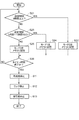
まず、ステップS21では、スリープタイマの設定時間が3時間以上であるか否かを判
定し、3時間以上であるときには、ステップS22に移行し、3時間以上でないときには
ステップS23に移行する。ステップS22では、モード2をメモリの所定記憶領域に記
憶してステップS26に移行する。
First, in step S21, it is determined whether or not the set time of the sleep timer is 3 hours or more. If it is 3 hours or more, the process proceeds to step S22, and if it is not 3 hours or more, the process proceeds to step S23. In step S22,
ステップS23では、スリープタイマの設定時間が1時間〜1時間45分の範囲内であ
るか否かを判定し、1時間〜1時間45分の範囲内であるときにはステップS24に移行
し、1時間〜1時間45分の範囲内でないときにはステップS25に移行する。ステップ
S24では、モード1をメモリの所定記憶領域に記憶してステップS26に移行する。
In step S23, it is determined whether or not the set time of the sleep timer is in the range of 1 hour to 1 hour 45 minutes. If it is in the range of 1 hour to 1 hour 45 minutes, the process proceeds to step S24, and 1 hour When it is not within the range of ˜1 hour 45 minutes, the process proceeds to step S25. In step S24,
ステップS25では、モード0をメモリの所定記憶領域に記憶してステップS26に移
行する。ステップS26では、スリープタイマ時間が終了したか否かを判定し、終了でな
いときは再びステップS21にもどる。スリープタイマ時間が終了のときはステップS1
1に移行する。ステップS11以降は前記第1の実施形態と同様に、ステップS11で再
生部2を停止し、次いでステップS12でランプ36を停止し、ステップS13で投写部
3を停止する。
In step S25, mode 0 is stored in a predetermined storage area of the memory, and the process proceeds to step S26. In step S26, it is determined whether or not the sleep timer time has expired. If not, the process returns to step S21 again. When the sleep timer has expired, step S1
Move to 1. After step S11, as in the first embodiment, the
以上のステップS21〜26は再生制御部23において実行され、ステップS11〜1
3は、再生制御部23及び投写制御部31において実行される。
The above steps S21 to S26 are executed in the
3 is executed in the
そして、再生部2及び投写部3の電源がオンされて、操作部5の所定のキー操作により
再生部2の再生の開始(再開)の操作が行なわれると、再生制御部23において、メモリ
に記憶されたDVD7の再生停止位置データのコマンドが再生動作部21に入力され、再
生動作部21は再生停止位置からDVD7を後戻り回転する。DVD7が後戻りする信号
は、前記再生停止位置の記憶フローにおいて、モード2が記憶されている場合は1分、モ
ード1の場合は30秒、モード0の場合は10秒間分だけDVD7を後戻りさせて、後戻
りした位置から再生を開始する。
When the
本実施形態によれば、スリープタイマの時間設定が長い程、DVD7が後戻りする再生
動作時間が長く設定されるので、再生停止したDVD7の続きの再生が開始された時に、
例えば映画等のストーリーを思い出すことができる。あるいは、見落としてしまい、見て
ないかもしれない場面から再生が開始されることもあり、映画等を効率良く鑑賞すること
ができる。しかも再生戻し時間が自動的に設定されるので、使い勝手の良いプロジェクタ
を得ることができる。
(第3の実施形態)
According to the present embodiment, the longer the time setting of the sleep timer is, the longer the playback operation time for which the DVD 7 returns is set. Therefore, when the playback of the DVD 7 that has been stopped playing is started,
For example, you can remember stories such as movies. Or it may be overlooked and playback may be started from a scene that may not be seen, so that movies and the like can be efficiently viewed. In addition, since the playback return time is automatically set, a user-friendly projector can be obtained.
(Third embodiment)
スリープタイマ機能の別の実施形態を説明する。本実施形態は、スリープタイマの設定
時間の経過(すなわち、スリープタイマの残り時間の減少)に対応して、液晶パネル34
に光を投射するランプ36の電力値を低減するスリープタイマ機能である。DVD7の再
生停止位置の記憶フロー及び電源制御フローを、図5のフローチャートに基づいて説明す
る。
Another embodiment of the sleep timer function will be described. In the present embodiment, the
This is a sleep timer function for reducing the power value of the
DVD7の再生停止位置からの再生戻し時間がセットされ、スリープタイマが開始され
た状態にあるDVD7の再生中(投写部3の投写中)に、図5のフローチャートで示す処
理が実行される。
The process shown in the flowchart of FIG. 5 is executed during playback of the DVD 7 in the state where the playback return time from the playback stop position of the DVD 7 is set and the sleep timer is started (during projection of the projection unit 3).
まず、ステップS31では、スリープタイマ時間が終了したか否かを判定し、終了でな
いときはステップS32に移行し、スリープタイマ時間が終了のときはステップS11に
移行する。
First, in step S31, it is determined whether or not the sleep timer period has expired. If not, the process proceeds to step S32. If the sleep timer period has expired, the process proceeds to step S11.
ステップS32では、スリープタイマの残り時間が45分〜31分の範囲内であるか否
かを判定し、45分〜31分の範囲内であるときにはステップS33に移行し、45分〜
31分の範囲内でないときにはステップS34に移行する。ステップS33では、投写制
御部31はバラスト35にディマー1のランプ制御信号に切替えてステップS31に戻る
。
In step S32, it is determined whether or not the remaining time of the sleep timer is within a range of 45 minutes to 31 minutes, and when it is within a range of 45 minutes to 31 minutes, the process proceeds to step S33,
When it is not within the range of 31 minutes, the process proceeds to step S34. In step S33, the
ステップS34では、スリープタイマの残り時間が30分〜16分の範囲内であるか否
かを判定し、30分〜16分の範囲内であるときにはステップS35に移行し、30分〜
16分の範囲内でないときにはステップS36に移行する。ステップS35では、投写制
御部31はバラスト35にディマー2のランプ制御信号に切替えてステップS31に戻る
。ステップS36では、投写制御部31はバラスト35にディマー3のランプ制御信号に
切替えてステップS31に戻る。
In step S34, it is determined whether or not the remaining time of the sleep timer is within a range of 30 minutes to 16 minutes. When the remaining time is within a range of 30 minutes to 16 minutes, the process proceeds to step S35, and 30 minutes to
When it is not within the range of 16 minutes, the process proceeds to step S36. In step S35, the
ステップS11以降は前記第1及び第2の実施形態と同様に、ステップS11で再生部
2を停止し、次いでステップS12でランプ36を停止し、ステップS13で投写部3を
停止する。
以上のステップS31〜34は再生制御部23において実行され、ステップS11〜1
3は、再生制御部23及び投写制御部31において実行される。
After step S11, as in the first and second embodiments, the
The above steps S31 to 34 are executed in the
3 is executed in the
投写制御部31がバラスト35に入力するランプ制御信号は、バラスト35からランプ
36への供給電力量を制御する信号であり、ディマー1には、例えば通常供給電力量の8
0%の電力量を供給し、ディマー2には、通常供給電力量の70%、ディマー3には、通
常供給電力量の60%の電力量を供給する。
The lamp control signal input to the
A power amount of 0% is supplied, 70% of the normal supply power amount is supplied to the
本実施形態によれば、DVD7の再生中(投写部3の投写中)に、スリープタイマの経
過時間と共にスクリーン8に投影される画像が、経過時間の段階毎にだんだん暗くなるこ
とにより、投写される画像(スクリーン8)でスリープタイマのおおまかな残り時間を知
ることができる。また、暗めの環境下で映画等の動画像を再生して鑑賞する場合に、タイ
マ設定部25の表示器55表示されるスリープタイマの残り時間を確認する必要がなくな
る。
According to the present embodiment, during reproduction of the DVD 7 (during projection by the projection unit 3), the image projected on the screen 8 together with the elapsed time of the sleep timer is projected as it gradually becomes darker at each elapsed time stage. The approximate remaining time of the sleep timer can be known from the image (screen 8). Further, when a moving image such as a movie is reproduced and viewed in a dark environment, it is not necessary to check the remaining time of the sleep timer displayed on the
その他の変形例を以下に記載する。
(変形例1)
Other modifications will be described below.
(Modification 1)
タイマ24及びタイマ設定部25を、再生部2の再生制御部23に接続して構成した場
合で説明したが、投写部3の投写制御部31に接続された場合であっても良い。また、再
生制御部23と投写制御部31の二つの制御部で構成した場合で説明したが一つの制御部
で構成してもよい。
(変形例2)
Although the case where the
(Modification 2)
液晶プロジェクタ1は、DVD7に記憶されている動画像等を再生する再生部2と、再
生部2において再生された動画像をスクリーン8などに投写する投写部3とが一体的に構
成された場合で説明したが、再生装置と液晶プロジェクタとの2体に構成し、有線あるい
は無線の所定のI/F(インタフェイス)を各々の装置に備えた場合であってもよい。
(変形例3)
In the
(Modification 3)
実施形態における、DVD7の再生停止位置から後戻りする再生戻し時間、ランプ36
の電力値を低減するスリープタイマの残り時間、及び再生戻し時間に対応するスリープタ
イマの設定時間等は、再生部2や投写部3の性能等を考慮して任意に決めることができる
。例えば、再生戻し時間を5分、10分、15分に設定することもできる。また、電力値
を低減するスリープタイマの残り時間を10分以内(ディマー1)、5分以内(ディマー
2)、1分以内(ディマー3)としてもよい。
(変形例4)
In the embodiment, the playback return time for returning backward from the playback stop position of the DVD 7, the
The remaining time of the sleep timer for reducing the power value of the sleep timer, the set time of the sleep timer corresponding to the playback return time, and the like can be arbitrarily determined in consideration of the performance of the
(Modification 4)
第1の実施形態と第3の実施形態、第2の実施形態と第3の実施形態の組み合わせであ
ってもよい。
(変形例5)
A combination of the first embodiment and the third embodiment, or the second embodiment and the third embodiment may be used.
(Modification 5)
第2の実施形態において、後戻りの時間を設定できるようにしてもよい。例えば、スリ
ープタイマ設定時間の10%、5%、1%のように割合で設定をする。
(変形例6)
In the second embodiment, it may be possible to set a backtracking time. For example, the sleep timer setting time is set at a ratio such as 10%, 5%, and 1%.
(Modification 6)
タイマ設定部25は、メニュー画面にしてスクリーン8に投写させて、操作部5の操作
によりスリープタイマ設定時間や後戻りする再生動作時間(再生戻し時間)を設定するよ
うにしてもよい。
(変形例7)
The
(Modification 7)
前記各実施形態では、スリープタイマ設定時間、再生戻し時間、電力値を低減するスリ
ープタイマの残り時間を3段階に分けたが、これに限定されない。任意の値を設定入力で
きるようにしてもよい。
In each of the above embodiments, the sleep timer setting time, the playback return time, and the remaining time of the sleep timer for reducing the power value are divided into three stages, but the present invention is not limited to this. An arbitrary value may be set and input.
1…表示装置としての液晶プロジェクタ、2…再生部、3…表示部としての投写部、4
…電源部、4a…再生電源部、4b…投写電源部、5…操作部、7…記憶媒体としてのD
VD、21…再生動作部、22…信号処理部、23…再生制御部、24…タイマ、25…
タイマ設定部、26…記憶手段としてのメモリ、31…投写制御部、32…画像処理部、
33…LCD駆動回路、34…液晶パネル、35…バラスト、36…ランプ、38…冷却
ファン、51…セットキー、52…セレクトキー、53…セットキー、54…スタートキ
ー、55…表示器。
DESCRIPTION OF
... power supply unit, 4a ... reproduction power supply unit, 4b ... projection power supply unit, 5 ... operation unit, 7 ... D as storage medium
VD, 21 ... reproduction operation unit, 22 ... signal processing unit, 23 ... reproduction control unit, 24 ... timer, 25 ...
Timer setting unit, 26... Memory as storage means, 31... Projection control unit, 32.
33 ... LCD drive circuit, 34 ... Liquid crystal panel, 35 ... Ballast, 36 ... Lamp, 38 ... Cooling fan, 51 ... Set key, 52 ... Select key, 53 ... Set key, 54 ... Start key, 55 ... Display.
Claims (6)
示する表示部とを備え、設定時間が経過することで前記再生部の再生動作及び前記表示部
の表示を停止させるスリープタイマ機能を有する表示装置であって、
前記記憶媒体の停止位置情報を記憶する記憶手段を備え、前記スリープタイマの設定時
間の経過により前記再生部の再生動作を停止し、前記再生部の再生動作の停止と共に停止
する前記記憶媒体の停止位置情報を前記記憶手段に記憶し、前記再生部は前記停止位置情
報に対応する位置から所定の再生動作時間分だけ後戻りした位置から再生動作を開始する
ことを特徴とする表示装置。 A reproduction unit that reproduces an image stored in a storage medium; and a display unit that displays an image reproduced by the reproduction unit, and the reproduction operation of the reproduction unit and the display unit A display device having a sleep timer function for stopping display,
Storage means for storing stop position information of the storage medium, stopping the reproduction operation of the reproduction unit when the set time of the sleep timer elapses, and stopping the storage medium that stops together with the stop of the reproduction operation of the reproduction unit Position information is memorize | stored in the said memory | storage means, The said reproduction | regeneration part starts reproduction | regeneration operation | movement from the position back | round | back for predetermined reproduction | regeneration operation | movement time from the position corresponding to the said stop position information.
前記停止位置から後戻りする所定の再生動作時間は、前記スリープタイマの設定時間の
長さに応じた時間に設定されることを特徴とする表示装置。 The display device according to claim 1,
The display apparatus according to claim 1, wherein the predetermined playback operation time returning from the stop position is set to a time corresponding to the length of the set time of the sleep timer.
前記表示部は、光源から照射された光を変調する空間光変調素子を備え、前記停止位置
から後戻りする再生動作時間を入力操作により設定する設定手段を備え、前記再生部は、
前記設定手段に設定された時間と前記光源が所定の輝度値に達する所定の再生動作時間を
加算した時間分、後戻りした位置から再生動作を開始することを特徴とする表示装置。 The display device according to claim 1,
The display unit includes a spatial light modulation element that modulates light emitted from a light source, and includes a setting unit that sets a reproduction operation time to return from the stop position by an input operation, and the reproduction unit includes:
A display device, wherein a reproduction operation is started from a position that is set back by a time obtained by adding a time set by the setting means and a predetermined reproduction operation time at which the light source reaches a predetermined luminance value.
前記表示部は、前記光源に供給する電力値を制御する電力制御部を備え、前記電力制御
部は前記スリープタイマの残り時間の減少に対応して電力値を低減することを特徴とする
表示装置。 The display device according to claim 3,
The display unit includes a power control unit that controls a power value supplied to the light source, and the power control unit reduces the power value in response to a decrease in a remaining time of the sleep timer. .
前記表示部は、前記光源を冷却する冷却ファンを備え、前記スリープタイマの設定時間
を経過後に、前記再生部の停止、前記光源の消灯、前記冷却ファンの停止の順に電源部を
制御する制御部を有することを特徴とする表示装置。 The display device according to claim 3 or claim 4,
The display unit includes a cooling fan that cools the light source, and controls a power source unit in the order of stopping the reproduction unit, turning off the light source, and stopping the cooling fan after the set time of the sleep timer has elapsed. A display device comprising:
前記再生部の再生動作中に前記表示部の光源が消灯したことを検出すると、前記光源が
消灯した時点の前記記憶媒体の再生位置情報を前記記憶手段に記憶し、前記再生部は、前
記記憶手段に記憶された再生位置情報に対応する位置から、前記光源が所定の輝度値に達
する所定の再生動作時間分だけ後戻りした位置から、前記記憶手段の再生動作を開始する
ことを特徴とする表示装置。
The display device according to any one of claims 3 to 5,
When it is detected that the light source of the display unit is turned off during the reproduction operation of the reproduction unit, reproduction position information of the storage medium at the time when the light source is turned off is stored in the storage unit, and the reproduction unit stores the storage A display operation characterized by starting the reproduction operation of the storage means from a position backed by a predetermined reproduction operation time when the light source reaches a predetermined luminance value from a position corresponding to the reproduction position information stored in the means apparatus.
Priority Applications (1)
| Application Number | Priority Date | Filing Date | Title |
|---|---|---|---|
| JP2004111088A JP2005292707A (en) | 2004-04-05 | 2004-04-05 | Display device |
Applications Claiming Priority (1)
| Application Number | Priority Date | Filing Date | Title |
|---|---|---|---|
| JP2004111088A JP2005292707A (en) | 2004-04-05 | 2004-04-05 | Display device |
Publications (1)
| Publication Number | Publication Date |
|---|---|
| JP2005292707A true JP2005292707A (en) | 2005-10-20 |
Family
ID=35325659
Family Applications (1)
| Application Number | Title | Priority Date | Filing Date |
|---|---|---|---|
| JP2004111088A Withdrawn JP2005292707A (en) | 2004-04-05 | 2004-04-05 | Display device |
Country Status (1)
| Country | Link |
|---|---|
| JP (1) | JP2005292707A (en) |
Cited By (4)
| Publication number | Priority date | Publication date | Assignee | Title |
|---|---|---|---|---|
| JP2009140565A (en) * | 2007-12-06 | 2009-06-25 | Sharp Corp | Content reproduction apparatus, content reproduction method, and program |
| WO2011089833A1 (en) * | 2010-01-20 | 2011-07-28 | Semiconductor Energy Laboratory Co., Ltd. | Display device |
| JP2017219792A (en) * | 2016-06-10 | 2017-12-14 | 株式会社大谷デザイン研究所 | Display system |
| JP2021135318A (en) * | 2020-02-25 | 2021-09-13 | セイコーエプソン株式会社 | Display device control method, display device, and display system control method |
-
2004
- 2004-04-05 JP JP2004111088A patent/JP2005292707A/en not_active Withdrawn
Cited By (16)
| Publication number | Priority date | Publication date | Assignee | Title |
|---|---|---|---|---|
| JP2009140565A (en) * | 2007-12-06 | 2009-06-25 | Sharp Corp | Content reproduction apparatus, content reproduction method, and program |
| US10089946B2 (en) | 2010-01-20 | 2018-10-02 | Semiconductor Energy Laboratory Co., Ltd. | Display device |
| WO2011089833A1 (en) * | 2010-01-20 | 2011-07-28 | Semiconductor Energy Laboratory Co., Ltd. | Display device |
| CN102714024A (en) * | 2010-01-20 | 2012-10-03 | 株式会社半导体能源研究所 | Display device |
| US8957881B2 (en) | 2010-01-20 | 2015-02-17 | Semiconductor Energy Laboratory Co., Ltd. | Display device |
| CN102714024B (en) * | 2010-01-20 | 2015-09-02 | 株式会社半导体能源研究所 | Display device |
| US9443482B2 (en) | 2010-01-20 | 2016-09-13 | Semiconductor Energy Laboratory Co., Ltd. | Display device |
| JP2011170329A (en) * | 2010-01-20 | 2011-09-01 | Semiconductor Energy Lab Co Ltd | Display device |
| US12159600B2 (en) | 2010-01-20 | 2024-12-03 | Semiconductor Energy Laboratory Co., Ltd. | Display device |
| US11790866B1 (en) | 2010-01-20 | 2023-10-17 | Semiconductor Energy Laboratory Co., Ltd. | Display device |
| US11081072B2 (en) | 2010-01-20 | 2021-08-03 | Semiconductor Energy Laboratory Co., Ltd. | Display device |
| US10580373B2 (en) | 2010-01-20 | 2020-03-03 | Semiconductor Energy Laboratory Co., Ltd. | Display device |
| US11462186B2 (en) | 2010-01-20 | 2022-10-04 | Semiconductor Energy Laboratory Co., Ltd. | Display device |
| JP2017219792A (en) * | 2016-06-10 | 2017-12-14 | 株式会社大谷デザイン研究所 | Display system |
| US11539912B2 (en) | 2020-02-25 | 2022-12-27 | Seiko Epson Corporation | Method for controlling display apparatus, display apparatus, and method for controlling display system |
| JP2021135318A (en) * | 2020-02-25 | 2021-09-13 | セイコーエプソン株式会社 | Display device control method, display device, and display system control method |
Similar Documents
| Publication | Publication Date | Title |
|---|---|---|
| US8083356B2 (en) | Methods and systems for improving operation of a video projector | |
| KR101164067B1 (en) | Projector and control method of projector | |
| CN101329499B (en) | Projection device and operation control method of projection device | |
| JP2014126572A (en) | Projector and control method of projector | |
| JP2009036870A (en) | Projector device and control method of projector device | |
| JP2004021218A (en) | Image display apparatus, power saving mode switching method, and program | |
| JP2003330115A (en) | Projector control for no input signal status | |
| JP2005292707A (en) | Display device | |
| JP2009135877A (en) | Projector and control method thereof | |
| JP5083506B2 (en) | Projector, program, and information storage medium | |
| JP2011050018A (en) | Video projector, and video display system | |
| JP2006119399A (en) | Image display device | |
| JP2006243551A (en) | Projector and projector lamp control | |
| JP2006119196A (en) | Video display device | |
| JP4997996B2 (en) | Projector and projector control method | |
| JP2009229924A (en) | Projection device, projection method and program | |
| JP2009258333A (en) | Projector and its control method | |
| JP2011095292A (en) | Projector and method for controlling the projector | |
| JP2009099171A (en) | Image display device, projector, and power supply control method | |
| JP2005227537A (en) | projector | |
| JP2012173451A (en) | Projector, and control method of projector | |
| JP5256827B2 (en) | Projection apparatus, projection method, and program | |
| JP2006317485A (en) | Projector and control method thereof | |
| JP2011066749A (en) | Projector and method of controlling the same | |
| JP2009003001A (en) | Projector and control method |
Legal Events
| Date | Code | Title | Description |
|---|---|---|---|
| A300 | Withdrawal of application because of no request for examination |
Free format text: JAPANESE INTERMEDIATE CODE: A300 Effective date: 20070605 |