JP2005292656A - Manufacturing device and manufacturing method of plastic optical fiber - Google Patents
Manufacturing device and manufacturing method of plastic optical fiber Download PDFInfo
- Publication number
- JP2005292656A JP2005292656A JP2004110242A JP2004110242A JP2005292656A JP 2005292656 A JP2005292656 A JP 2005292656A JP 2004110242 A JP2004110242 A JP 2004110242A JP 2004110242 A JP2004110242 A JP 2004110242A JP 2005292656 A JP2005292656 A JP 2005292656A
- Authority
- JP
- Japan
- Prior art keywords
- optical fiber
- plastic optical
- polymerization
- heating furnace
- preform
- Prior art date
- Legal status (The legal status is an assumption and is not a legal conclusion. Google has not performed a legal analysis and makes no representation as to the accuracy of the status listed.)
- Pending
Links
- 239000013308 plastic optical fiber Substances 0.000 title claims abstract description 148
- 238000004519 manufacturing process Methods 0.000 title claims abstract description 72
- 238000010438 heat treatment Methods 0.000 claims abstract description 98
- 239000003566 sealing material Substances 0.000 claims abstract description 57
- 239000007789 gas Substances 0.000 claims abstract description 35
- IJGRMHOSHXDMSA-UHFFFAOYSA-N Atomic nitrogen Chemical compound N#N IJGRMHOSHXDMSA-UHFFFAOYSA-N 0.000 claims abstract description 13
- 238000002844 melting Methods 0.000 claims abstract description 11
- 230000008018 melting Effects 0.000 claims abstract description 11
- 239000000463 material Substances 0.000 claims description 46
- 239000013307 optical fiber Substances 0.000 claims description 22
- 229920003023 plastic Polymers 0.000 claims description 15
- 239000004033 plastic Substances 0.000 claims description 15
- XKRFYHLGVUSROY-UHFFFAOYSA-N Argon Chemical compound [Ar] XKRFYHLGVUSROY-UHFFFAOYSA-N 0.000 claims description 12
- 230000002093 peripheral effect Effects 0.000 claims description 12
- 229910052786 argon Inorganic materials 0.000 claims description 6
- 239000001307 helium Substances 0.000 claims description 6
- 229910052734 helium Inorganic materials 0.000 claims description 6
- SWQJXJOGLNCZEY-UHFFFAOYSA-N helium atom Chemical compound [He] SWQJXJOGLNCZEY-UHFFFAOYSA-N 0.000 claims description 6
- 229910052757 nitrogen Inorganic materials 0.000 claims description 5
- 238000005192 partition Methods 0.000 claims description 2
- 229910001873 dinitrogen Inorganic materials 0.000 abstract description 3
- 239000011162 core material Substances 0.000 description 164
- 238000006116 polymerization reaction Methods 0.000 description 156
- 229920000642 polymer Polymers 0.000 description 71
- 239000000178 monomer Substances 0.000 description 52
- 230000003287 optical effect Effects 0.000 description 52
- 238000000034 method Methods 0.000 description 50
- 239000000203 mixture Substances 0.000 description 44
- 238000009826 distribution Methods 0.000 description 32
- 230000005540 biological transmission Effects 0.000 description 28
- 238000000576 coating method Methods 0.000 description 24
- 239000003505 polymerization initiator Substances 0.000 description 24
- 238000001125 extrusion Methods 0.000 description 23
- 239000010410 layer Substances 0.000 description 23
- 239000002994 raw material Substances 0.000 description 22
- 239000011248 coating agent Substances 0.000 description 20
- 238000005253 cladding Methods 0.000 description 19
- 239000007788 liquid Substances 0.000 description 17
- 239000011247 coating layer Substances 0.000 description 16
- 238000001816 cooling Methods 0.000 description 16
- 229920005989 resin Polymers 0.000 description 14
- 239000011347 resin Substances 0.000 description 14
- 239000012986 chain transfer agent Substances 0.000 description 13
- 239000003795 chemical substances by application Substances 0.000 description 13
- XLYOFNOQVPJJNP-UHFFFAOYSA-N water Substances O XLYOFNOQVPJJNP-UHFFFAOYSA-N 0.000 description 13
- 150000001875 compounds Chemical class 0.000 description 12
- 229920001577 copolymer Polymers 0.000 description 12
- 229920001971 elastomer Polymers 0.000 description 11
- 239000012792 core layer Substances 0.000 description 10
- 239000002019 doping agent Substances 0.000 description 10
- 238000000465 moulding Methods 0.000 description 10
- 230000008569 process Effects 0.000 description 10
- VYPSYNLAJGMNEJ-UHFFFAOYSA-N silicon dioxide Inorganic materials O=[Si]=O VYPSYNLAJGMNEJ-UHFFFAOYSA-N 0.000 description 10
- 238000010521 absorption reaction Methods 0.000 description 9
- -1 decanyl methacrylate Chemical compound 0.000 description 9
- 239000011261 inert gas Substances 0.000 description 9
- 239000000155 melt Substances 0.000 description 9
- 239000003570 air Substances 0.000 description 8
- 230000000694 effects Effects 0.000 description 8
- 229910052731 fluorine Inorganic materials 0.000 description 8
- 239000005060 rubber Substances 0.000 description 8
- 238000007789 sealing Methods 0.000 description 8
- 125000006850 spacer group Chemical group 0.000 description 8
- YCKRFDGAMUMZLT-UHFFFAOYSA-N Fluorine atom Chemical compound [F] YCKRFDGAMUMZLT-UHFFFAOYSA-N 0.000 description 7
- 230000006378 damage Effects 0.000 description 7
- 230000007423 decrease Effects 0.000 description 7
- 239000011737 fluorine Substances 0.000 description 7
- 230000000379 polymerizing effect Effects 0.000 description 7
- 238000011144 upstream manufacturing Methods 0.000 description 7
- LTYMSROWYAPPGB-UHFFFAOYSA-N diphenyl sulfide Chemical compound C=1C=CC=CC=1SC1=CC=CC=C1 LTYMSROWYAPPGB-UHFFFAOYSA-N 0.000 description 6
- 238000002474 experimental method Methods 0.000 description 6
- 239000000835 fiber Substances 0.000 description 6
- 238000012545 processing Methods 0.000 description 6
- 229920002379 silicone rubber Polymers 0.000 description 6
- 238000012360 testing method Methods 0.000 description 6
- VVQNEPGJFQJSBK-UHFFFAOYSA-N Methyl methacrylate Chemical compound COC(=O)C(C)=C VVQNEPGJFQJSBK-UHFFFAOYSA-N 0.000 description 5
- 239000002033 PVDF binder Substances 0.000 description 5
- 239000000654 additive Substances 0.000 description 5
- 230000008901 benefit Effects 0.000 description 5
- 230000000875 corresponding effect Effects 0.000 description 5
- 239000003063 flame retardant Substances 0.000 description 5
- 230000006870 function Effects 0.000 description 5
- 230000009477 glass transition Effects 0.000 description 5
- 230000006872 improvement Effects 0.000 description 5
- 229910052751 metal Inorganic materials 0.000 description 5
- 239000002184 metal Substances 0.000 description 5
- 229920002981 polyvinylidene fluoride Polymers 0.000 description 5
- 230000004044 response Effects 0.000 description 5
- 239000004945 silicone rubber Substances 0.000 description 5
- CERQOIWHTDAKMF-UHFFFAOYSA-N Methacrylic acid Chemical class CC(=C)C(O)=O CERQOIWHTDAKMF-UHFFFAOYSA-N 0.000 description 4
- 238000005452 bending Methods 0.000 description 4
- 230000015572 biosynthetic process Effects 0.000 description 4
- 238000009835 boiling Methods 0.000 description 4
- 230000006866 deterioration Effects 0.000 description 4
- 239000000377 silicon dioxide Substances 0.000 description 4
- 239000000126 substance Substances 0.000 description 4
- 229920005992 thermoplastic resin Polymers 0.000 description 4
- 238000012546 transfer Methods 0.000 description 4
- 238000002834 transmittance Methods 0.000 description 4
- JJHHIJFTHRNPIK-UHFFFAOYSA-N Diphenyl sulfoxide Chemical compound C=1C=CC=CC=1S(=O)C1=CC=CC=C1 JJHHIJFTHRNPIK-UHFFFAOYSA-N 0.000 description 3
- CERQOIWHTDAKMF-UHFFFAOYSA-M Methacrylate Chemical compound CC(=C)C([O-])=O CERQOIWHTDAKMF-UHFFFAOYSA-M 0.000 description 3
- 238000002485 combustion reaction Methods 0.000 description 3
- 230000000052 comparative effect Effects 0.000 description 3
- 238000007334 copolymerization reaction Methods 0.000 description 3
- 230000006837 decompression Effects 0.000 description 3
- WNAHIZMDSQCWRP-UHFFFAOYSA-N dodecane-1-thiol Chemical compound CCCCCCCCCCCCS WNAHIZMDSQCWRP-UHFFFAOYSA-N 0.000 description 3
- 239000000806 elastomer Substances 0.000 description 3
- 239000011521 glass Substances 0.000 description 3
- 229920001519 homopolymer Polymers 0.000 description 3
- 125000004435 hydrogen atom Chemical group [H]* 0.000 description 3
- 239000011159 matrix material Substances 0.000 description 3
- 229910000000 metal hydroxide Inorganic materials 0.000 description 3
- 150000004692 metal hydroxides Chemical class 0.000 description 3
- 210000002445 nipple Anatomy 0.000 description 3
- ZUOUZKKEUPVFJK-UHFFFAOYSA-N phenylbenzene Natural products C1=CC=CC=C1C1=CC=CC=C1 ZUOUZKKEUPVFJK-UHFFFAOYSA-N 0.000 description 3
- 229920003229 poly(methyl methacrylate) Polymers 0.000 description 3
- 239000004926 polymethyl methacrylate Substances 0.000 description 3
- 208000021560 premature ovarian failure 17 Diseases 0.000 description 3
- 239000011241 protective layer Substances 0.000 description 3
- 230000004043 responsiveness Effects 0.000 description 3
- 238000004513 sizing Methods 0.000 description 3
- RMVRSNDYEFQCLF-UHFFFAOYSA-N thiophenol Chemical compound SC1=CC=CC=C1 RMVRSNDYEFQCLF-UHFFFAOYSA-N 0.000 description 3
- 238000004506 ultrasonic cleaning Methods 0.000 description 3
- BQCIDUSAKPWEOX-UHFFFAOYSA-N 1,1-Difluoroethene Chemical compound FC(F)=C BQCIDUSAKPWEOX-UHFFFAOYSA-N 0.000 description 2
- CXWGKAYMVASWDQ-UHFFFAOYSA-N 1,2-dithiane Chemical class C1CCSSC1 CXWGKAYMVASWDQ-UHFFFAOYSA-N 0.000 description 2
- RNFJDJUURJAICM-UHFFFAOYSA-N 2,2,4,4,6,6-hexaphenoxy-1,3,5-triaza-2$l^{5},4$l^{5},6$l^{5}-triphosphacyclohexa-1,3,5-triene Chemical compound N=1P(OC=2C=CC=CC=2)(OC=2C=CC=CC=2)=NP(OC=2C=CC=CC=2)(OC=2C=CC=CC=2)=NP=1(OC=1C=CC=CC=1)OC1=CC=CC=C1 RNFJDJUURJAICM-UHFFFAOYSA-N 0.000 description 2
- YAJYJWXEWKRTPO-UHFFFAOYSA-N 2,3,3,4,4,5-hexamethylhexane-2-thiol Chemical compound CC(C)C(C)(C)C(C)(C)C(C)(C)S YAJYJWXEWKRTPO-UHFFFAOYSA-N 0.000 description 2
- OZAIFHULBGXAKX-UHFFFAOYSA-N 2-(2-cyanopropan-2-yldiazenyl)-2-methylpropanenitrile Chemical compound N#CC(C)(C)N=NC(C)(C)C#N OZAIFHULBGXAKX-UHFFFAOYSA-N 0.000 description 2
- AORMDLNPRGXHHL-UHFFFAOYSA-N 3-ethylpentane Chemical compound CCC(CC)CC AORMDLNPRGXHHL-UHFFFAOYSA-N 0.000 description 2
- 239000004342 Benzoyl peroxide Substances 0.000 description 2
- OMPJBNCRMGITSC-UHFFFAOYSA-N Benzoylperoxide Chemical compound C=1C=CC=CC=1C(=O)OOC(=O)C1=CC=CC=C1 OMPJBNCRMGITSC-UHFFFAOYSA-N 0.000 description 2
- KAKZBPTYRLMSJV-UHFFFAOYSA-N Butadiene Chemical compound C=CC=C KAKZBPTYRLMSJV-UHFFFAOYSA-N 0.000 description 2
- CURLTUGMZLYLDI-UHFFFAOYSA-N Carbon dioxide Chemical compound O=C=O CURLTUGMZLYLDI-UHFFFAOYSA-N 0.000 description 2
- LFQSCWFLJHTTHZ-UHFFFAOYSA-N Ethanol Chemical compound CCO LFQSCWFLJHTTHZ-UHFFFAOYSA-N 0.000 description 2
- JOYRKODLDBILNP-UHFFFAOYSA-N Ethyl urethane Chemical compound CCOC(N)=O JOYRKODLDBILNP-UHFFFAOYSA-N 0.000 description 2
- RRHGJUQNOFWUDK-UHFFFAOYSA-N Isoprene Chemical compound CC(=C)C=C RRHGJUQNOFWUDK-UHFFFAOYSA-N 0.000 description 2
- BAPJBEWLBFYGME-UHFFFAOYSA-N Methyl acrylate Chemical compound COC(=O)C=C BAPJBEWLBFYGME-UHFFFAOYSA-N 0.000 description 2
- 239000004698 Polyethylene Substances 0.000 description 2
- 239000004743 Polypropylene Substances 0.000 description 2
- PPBRXRYQALVLMV-UHFFFAOYSA-N Styrene Chemical compound C=CC1=CC=CC=C1 PPBRXRYQALVLMV-UHFFFAOYSA-N 0.000 description 2
- YSMRWXYRXBRSND-UHFFFAOYSA-N TOTP Chemical compound CC1=CC=CC=C1OP(=O)(OC=1C(=CC=CC=1)C)OC1=CC=CC=C1C YSMRWXYRXBRSND-UHFFFAOYSA-N 0.000 description 2
- 239000004809 Teflon Substances 0.000 description 2
- 229920006362 Teflon® Polymers 0.000 description 2
- 229920006311 Urethane elastomer Polymers 0.000 description 2
- 125000005396 acrylic acid ester group Chemical group 0.000 description 2
- 239000003963 antioxidant agent Substances 0.000 description 2
- WPYMKLBDIGXBTP-UHFFFAOYSA-N benzoic acid Chemical compound OC(=O)C1=CC=CC=C1 WPYMKLBDIGXBTP-UHFFFAOYSA-N 0.000 description 2
- 235000019400 benzoyl peroxide Nutrition 0.000 description 2
- SESFRYSPDFLNCH-UHFFFAOYSA-N benzyl benzoate Chemical compound C=1C=CC=CC=1C(=O)OCC1=CC=CC=C1 SESFRYSPDFLNCH-UHFFFAOYSA-N 0.000 description 2
- 239000004305 biphenyl Substances 0.000 description 2
- 235000010290 biphenyl Nutrition 0.000 description 2
- 125000006267 biphenyl group Chemical group 0.000 description 2
- 238000012662 bulk polymerization Methods 0.000 description 2
- WQAQPCDUOCURKW-UHFFFAOYSA-N butanethiol Chemical compound CCCCS WQAQPCDUOCURKW-UHFFFAOYSA-N 0.000 description 2
- 229910052799 carbon Inorganic materials 0.000 description 2
- 230000015556 catabolic process Effects 0.000 description 2
- 239000000919 ceramic Substances 0.000 description 2
- 230000008859 change Effects 0.000 description 2
- 238000006243 chemical reaction Methods 0.000 description 2
- 238000004891 communication Methods 0.000 description 2
- 230000001276 controlling effect Effects 0.000 description 2
- 239000000498 cooling water Substances 0.000 description 2
- 238000005520 cutting process Methods 0.000 description 2
- 238000007872 degassing Methods 0.000 description 2
- 238000006731 degradation reaction Methods 0.000 description 2
- 229910052805 deuterium Inorganic materials 0.000 description 2
- 125000004431 deuterium atom Chemical group 0.000 description 2
- DWNAQMUDCDVSLT-UHFFFAOYSA-N diphenyl phthalate Chemical compound C=1C=CC=C(C(=O)OC=2C=CC=CC=2)C=1C(=O)OC1=CC=CC=C1 DWNAQMUDCDVSLT-UHFFFAOYSA-N 0.000 description 2
- CZZYITDELCSZES-UHFFFAOYSA-N diphenylmethane Chemical compound C=1C=CC=CC=1CC1=CC=CC=C1 CZZYITDELCSZES-UHFFFAOYSA-N 0.000 description 2
- 239000000428 dust Substances 0.000 description 2
- 238000005516 engineering process Methods 0.000 description 2
- 239000005038 ethylene vinyl acetate Substances 0.000 description 2
- 229920006244 ethylene-ethyl acrylate Polymers 0.000 description 2
- 238000005286 illumination Methods 0.000 description 2
- 230000001771 impaired effect Effects 0.000 description 2
- 239000003999 initiator Substances 0.000 description 2
- 239000011810 insulating material Substances 0.000 description 2
- 239000000314 lubricant Substances 0.000 description 2
- 230000007246 mechanism Effects 0.000 description 2
- KZCOBXFFBQJQHH-UHFFFAOYSA-N octane-1-thiol Chemical compound CCCCCCCCS KZCOBXFFBQJQHH-UHFFFAOYSA-N 0.000 description 2
- 239000003921 oil Substances 0.000 description 2
- 230000003647 oxidation Effects 0.000 description 2
- 238000007254 oxidation reaction Methods 0.000 description 2
- XNGIFLGASWRNHJ-UHFFFAOYSA-N phthalic acid Chemical compound OC(=O)C1=CC=CC=C1C(O)=O XNGIFLGASWRNHJ-UHFFFAOYSA-N 0.000 description 2
- 239000002985 plastic film Substances 0.000 description 2
- 229920001200 poly(ethylene-vinyl acetate) Polymers 0.000 description 2
- 239000004417 polycarbonate Substances 0.000 description 2
- 229920000515 polycarbonate Polymers 0.000 description 2
- 229920000728 polyester Polymers 0.000 description 2
- 229920000573 polyethylene Polymers 0.000 description 2
- 229920001155 polypropylene Polymers 0.000 description 2
- 230000002265 prevention Effects 0.000 description 2
- 239000010453 quartz Substances 0.000 description 2
- 239000002516 radical scavenger Substances 0.000 description 2
- 230000009467 reduction Effects 0.000 description 2
- 239000007787 solid Substances 0.000 description 2
- 229910001220 stainless steel Inorganic materials 0.000 description 2
- 238000003786 synthesis reaction Methods 0.000 description 2
- 238000010998 test method Methods 0.000 description 2
- 229920002725 thermoplastic elastomer Polymers 0.000 description 2
- XZZNDPSIHUTMOC-UHFFFAOYSA-N triphenyl phosphate Chemical compound C=1C=CC=CC=1OP(OC=1C=CC=CC=1)(=O)OC1=CC=CC=C1 XZZNDPSIHUTMOC-UHFFFAOYSA-N 0.000 description 2
- 229920001567 vinyl ester resin Polymers 0.000 description 2
- 125000000391 vinyl group Chemical group [H]C([*])=C([H])[H] 0.000 description 2
- 238000004804 winding Methods 0.000 description 2
- ZSVFYHKZQNDJEV-UHFFFAOYSA-N (2,3,4-tribromophenyl) 2-methylprop-2-enoate Chemical compound CC(=C)C(=O)OC1=CC=C(Br)C(Br)=C1Br ZSVFYHKZQNDJEV-UHFFFAOYSA-N 0.000 description 1
- MYOQALXKVOJACM-UHFFFAOYSA-N (2-methylpropan-2-yl)oxy pentaneperoxoate Chemical compound CCCCC(=O)OOOC(C)(C)C MYOQALXKVOJACM-UHFFFAOYSA-N 0.000 description 1
- KDGNCLDCOVTOCS-UHFFFAOYSA-N (2-methylpropan-2-yl)oxy propan-2-yl carbonate Chemical compound CC(C)OC(=O)OOC(C)(C)C KDGNCLDCOVTOCS-UHFFFAOYSA-N 0.000 description 1
- FMQPBWHSNCRVQJ-UHFFFAOYSA-N 1,1,1,3,3,3-hexafluoropropan-2-yl 2-methylprop-2-enoate Chemical compound CC(=C)C(=O)OC(C(F)(F)F)C(F)(F)F FMQPBWHSNCRVQJ-UHFFFAOYSA-N 0.000 description 1
- ZRKMQKLGEQPLNS-UHFFFAOYSA-N 1-Pentanethiol Chemical compound CCCCCS ZRKMQKLGEQPLNS-UHFFFAOYSA-N 0.000 description 1
- MZVABYGYVXBZDP-UHFFFAOYSA-N 1-adamantyl 2-methylprop-2-enoate Chemical compound C1C(C2)CC3CC2CC1(OC(=O)C(=C)C)C3 MZVABYGYVXBZDP-UHFFFAOYSA-N 0.000 description 1
- QTKPMCIBUROOGY-UHFFFAOYSA-N 2,2,2-trifluoroethyl 2-methylprop-2-enoate Chemical compound CC(=C)C(=O)OCC(F)(F)F QTKPMCIBUROOGY-UHFFFAOYSA-N 0.000 description 1
- CLISWDZSTWQFNX-UHFFFAOYSA-N 2,2,3,3,3-pentafluoropropyl 2-methylprop-2-enoate Chemical compound CC(=C)C(=O)OCC(F)(F)C(F)(F)F CLISWDZSTWQFNX-UHFFFAOYSA-N 0.000 description 1
- ZNJXRXXJPIFFAO-UHFFFAOYSA-N 2,2,3,3,4,4,5,5-octafluoropentyl 2-methylprop-2-enoate Chemical compound CC(=C)C(=O)OCC(F)(F)C(F)(F)C(F)(F)C(F)F ZNJXRXXJPIFFAO-UHFFFAOYSA-N 0.000 description 1
- IKZYSJAHCZYFHH-UHFFFAOYSA-N 2,2,3,3,4,4-hexafluorobutyl 2-methylprop-2-enoate Chemical compound CC(=C)C(=O)OCC(F)(F)C(F)(F)C(F)F IKZYSJAHCZYFHH-UHFFFAOYSA-N 0.000 description 1
- RSVZYSKAPMBSMY-UHFFFAOYSA-N 2,2,3,3-tetrafluoropropyl 2-methylprop-2-enoate Chemical compound CC(=C)C(=O)OCC(F)(F)C(F)F RSVZYSKAPMBSMY-UHFFFAOYSA-N 0.000 description 1
- AVTLBBWTUPQRAY-UHFFFAOYSA-N 2-(2-cyanobutan-2-yldiazenyl)-2-methylbutanenitrile Chemical compound CCC(C)(C#N)N=NC(C)(CC)C#N AVTLBBWTUPQRAY-UHFFFAOYSA-N 0.000 description 1
- SBYMUDUGTIKLCR-UHFFFAOYSA-N 2-chloroethenylbenzene Chemical compound ClC=CC1=CC=CC=C1 SBYMUDUGTIKLCR-UHFFFAOYSA-N 0.000 description 1
- TYCFGHUTYSLISP-UHFFFAOYSA-M 2-fluoroprop-2-enoate Chemical compound [O-]C(=O)C(F)=C TYCFGHUTYSLISP-UHFFFAOYSA-M 0.000 description 1
- JBTDFRNUVWFUGL-UHFFFAOYSA-N 3-aminopropyl carbamimidothioate;dihydrobromide Chemical compound Br.Br.NCCCSC(N)=N JBTDFRNUVWFUGL-UHFFFAOYSA-N 0.000 description 1
- HNGQQUDFJDROPY-UHFFFAOYSA-N 3-bromobenzenethiol Chemical compound SC1=CC=CC(Br)=C1 HNGQQUDFJDROPY-UHFFFAOYSA-N 0.000 description 1
- WRXOZRLZDJAYDR-UHFFFAOYSA-N 3-methylbenzenethiol Chemical compound CC1=CC=CC(S)=C1 WRXOZRLZDJAYDR-UHFFFAOYSA-N 0.000 description 1
- FTBCOQFMQSTCQQ-UHFFFAOYSA-N 4-bromobenzenethiol Chemical compound SC1=CC=C(Br)C=C1 FTBCOQFMQSTCQQ-UHFFFAOYSA-N 0.000 description 1
- WLHCBQAPPJAULW-UHFFFAOYSA-N 4-methylbenzenethiol Chemical compound CC1=CC=C(S)C=C1 WLHCBQAPPJAULW-UHFFFAOYSA-N 0.000 description 1
- WKBOTKDWSSQWDR-UHFFFAOYSA-N Bromine atom Chemical compound [Br] WKBOTKDWSSQWDR-UHFFFAOYSA-N 0.000 description 1
- OKTJSMMVPCPJKN-UHFFFAOYSA-N Carbon Chemical compound [C] OKTJSMMVPCPJKN-UHFFFAOYSA-N 0.000 description 1
- RYGMFSIKBFXOCR-UHFFFAOYSA-N Copper Chemical compound [Cu] RYGMFSIKBFXOCR-UHFFFAOYSA-N 0.000 description 1
- YZCKVEUIGOORGS-OUBTZVSYSA-N Deuterium Chemical compound [2H] YZCKVEUIGOORGS-OUBTZVSYSA-N 0.000 description 1
- JIGUQPWFLRLWPJ-UHFFFAOYSA-N Ethyl acrylate Chemical compound CCOC(=O)C=C JIGUQPWFLRLWPJ-UHFFFAOYSA-N 0.000 description 1
- RJUFJBKOKNCXHH-UHFFFAOYSA-N Methyl propionate Chemical compound CCC(=O)OC RJUFJBKOKNCXHH-UHFFFAOYSA-N 0.000 description 1
- 239000004677 Nylon Substances 0.000 description 1
- OAICVXFJPJFONN-UHFFFAOYSA-N Phosphorus Chemical compound [P] OAICVXFJPJFONN-UHFFFAOYSA-N 0.000 description 1
- 239000004952 Polyamide Substances 0.000 description 1
- XUIMIQQOPSSXEZ-UHFFFAOYSA-N Silicon Chemical compound [Si] XUIMIQQOPSSXEZ-UHFFFAOYSA-N 0.000 description 1
- XTXRWKRVRITETP-UHFFFAOYSA-N Vinyl acetate Chemical compound CC(=O)OC=C XTXRWKRVRITETP-UHFFFAOYSA-N 0.000 description 1
- BZHJMEDXRYGGRV-UHFFFAOYSA-N Vinyl chloride Chemical compound ClC=C BZHJMEDXRYGGRV-UHFFFAOYSA-N 0.000 description 1
- 229910001297 Zn alloy Inorganic materials 0.000 description 1
- IAXXETNIOYFMLW-COPLHBTASA-N [(1s,3s,4s)-4,7,7-trimethyl-3-bicyclo[2.2.1]heptanyl] 2-methylprop-2-enoate Chemical compound C1C[C@]2(C)[C@@H](OC(=O)C(=C)C)C[C@H]1C2(C)C IAXXETNIOYFMLW-COPLHBTASA-N 0.000 description 1
- YMOONIIMQBGTDU-VOTSOKGWSA-N [(e)-2-bromoethenyl]benzene Chemical compound Br\C=C\C1=CC=CC=C1 YMOONIIMQBGTDU-VOTSOKGWSA-N 0.000 description 1
- KYIKRXIYLAGAKQ-UHFFFAOYSA-N abcn Chemical compound C1CCCCC1(C#N)N=NC1(C#N)CCCCC1 KYIKRXIYLAGAKQ-UHFFFAOYSA-N 0.000 description 1
- 239000011358 absorbing material Substances 0.000 description 1
- XYLMUPLGERFSHI-UHFFFAOYSA-N alpha-Methylstyrene Chemical compound CC(=C)C1=CC=CC=C1 XYLMUPLGERFSHI-UHFFFAOYSA-N 0.000 description 1
- 229910052782 aluminium Inorganic materials 0.000 description 1
- XAGFODPZIPBFFR-UHFFFAOYSA-N aluminium Chemical compound [Al] XAGFODPZIPBFFR-UHFFFAOYSA-N 0.000 description 1
- WNROFYMDJYEPJX-UHFFFAOYSA-K aluminium hydroxide Chemical compound [OH-].[OH-].[OH-].[Al+3] WNROFYMDJYEPJX-UHFFFAOYSA-K 0.000 description 1
- 239000012080 ambient air Substances 0.000 description 1
- 150000001412 amines Chemical class 0.000 description 1
- 230000003321 amplification Effects 0.000 description 1
- 230000002528 anti-freeze Effects 0.000 description 1
- 230000003078 antioxidant effect Effects 0.000 description 1
- 229920006231 aramid fiber Polymers 0.000 description 1
- 230000002238 attenuated effect Effects 0.000 description 1
- 230000004888 barrier function Effects 0.000 description 1
- 229960002903 benzyl benzoate Drugs 0.000 description 1
- BMPVIOJNXPGHOC-UHFFFAOYSA-N bis(2,3,3-trimethylbutan-2-yl)diazene Chemical compound CC(C)(C)C(C)(C)N=NC(C)(C)C(C)(C)C BMPVIOJNXPGHOC-UHFFFAOYSA-N 0.000 description 1
- RYQCEARGGAZJGN-UHFFFAOYSA-N bis(2,3-dimethylbutan-2-yl)diazene Chemical compound CC(C)C(C)(C)N=NC(C)(C)C(C)C RYQCEARGGAZJGN-UHFFFAOYSA-N 0.000 description 1
- CSOXCCBZHKJVLZ-UHFFFAOYSA-N bis(2,3-dimethylpentan-3-yl)diazene Chemical compound CCC(C)(C(C)C)N=NC(C)(CC)C(C)C CSOXCCBZHKJVLZ-UHFFFAOYSA-N 0.000 description 1
- WPKWPKDNOPEODE-UHFFFAOYSA-N bis(2,4,4-trimethylpentan-2-yl)diazene Chemical compound CC(C)(C)CC(C)(C)N=NC(C)(C)CC(C)(C)C WPKWPKDNOPEODE-UHFFFAOYSA-N 0.000 description 1
- XRUJEOCEPGTJNX-UHFFFAOYSA-N bis(2,4-dimethylpentan-2-yl)diazene Chemical compound CC(C)CC(C)(C)N=NC(C)(C)CC(C)C XRUJEOCEPGTJNX-UHFFFAOYSA-N 0.000 description 1
- ZGXHUGQEDPPKGZ-UHFFFAOYSA-N bis(2-methylbutan-2-yl)diazene Chemical compound CCC(C)(C)N=NC(C)(C)CC ZGXHUGQEDPPKGZ-UHFFFAOYSA-N 0.000 description 1
- PEDAIVKHTRIDMZ-UHFFFAOYSA-N bis(2-methylhexan-2-yl)diazene Chemical compound CCCCC(C)(C)N=NC(C)(C)CCCC PEDAIVKHTRIDMZ-UHFFFAOYSA-N 0.000 description 1
- HAPMLSSJGUUMQE-UHFFFAOYSA-N bis(2-methylpentan-2-yl)diazene Chemical compound CCCC(C)(C)N=NC(C)(C)CCC HAPMLSSJGUUMQE-UHFFFAOYSA-N 0.000 description 1
- KPPBDZVMVVWVGA-UHFFFAOYSA-N bis(3-methylhexan-3-yl)diazene Chemical compound CCCC(C)(CC)N=NC(C)(CC)CCC KPPBDZVMVVWVGA-UHFFFAOYSA-N 0.000 description 1
- HJXOEVAWGZCKGE-UHFFFAOYSA-N bis(3-methylpentan-3-yl)diazene Chemical compound CCC(C)(CC)N=NC(C)(CC)CC HJXOEVAWGZCKGE-UHFFFAOYSA-N 0.000 description 1
- GDTBXPJZTBHREO-UHFFFAOYSA-N bromine Substances BrBr GDTBXPJZTBHREO-UHFFFAOYSA-N 0.000 description 1
- 229910052794 bromium Inorganic materials 0.000 description 1
- 229910002092 carbon dioxide Inorganic materials 0.000 description 1
- 239000001569 carbon dioxide Substances 0.000 description 1
- 229910010293 ceramic material Inorganic materials 0.000 description 1
- 238000004040 coloring Methods 0.000 description 1
- 239000000470 constituent Substances 0.000 description 1
- 230000002596 correlated effect Effects 0.000 description 1
- 239000013078 crystal Substances 0.000 description 1
- OIWOHHBRDFKZNC-UHFFFAOYSA-N cyclohexyl 2-methylprop-2-enoate Chemical compound CC(=C)C(=O)OC1CCCCC1 OIWOHHBRDFKZNC-UHFFFAOYSA-N 0.000 description 1
- 150000001975 deuterium Chemical group 0.000 description 1
- 238000011161 development Methods 0.000 description 1
- 238000010586 diagram Methods 0.000 description 1
- 150000001993 dienes Chemical class 0.000 description 1
- 125000005982 diphenylmethyl group Chemical group [H]C1=C([H])C([H])=C(C([H])=C1[H])C([H])(*)C1=C([H])C([H])=C([H])C([H])=C1[H] 0.000 description 1
- GKCPCPKXFGQXGS-UHFFFAOYSA-N ditert-butyldiazene Chemical compound CC(C)(C)N=NC(C)(C)C GKCPCPKXFGQXGS-UHFFFAOYSA-N 0.000 description 1
- IRFXVXBSIAKRJM-UHFFFAOYSA-N dodecane-1-thiol Chemical compound CCCCCCCCCCCCS.CCCCCCCCCCCCS IRFXVXBSIAKRJM-UHFFFAOYSA-N 0.000 description 1
- 229920006351 engineering plastic Polymers 0.000 description 1
- XJELOQYISYPGDX-UHFFFAOYSA-N ethenyl 2-chloroacetate Chemical compound ClCC(=O)OC=C XJELOQYISYPGDX-UHFFFAOYSA-N 0.000 description 1
- XNICETZFWREDRJ-UHFFFAOYSA-N ethyl 2-[(1-ethoxy-2-methyl-1-oxopropan-2-yl)diazenyl]-2-methylpropanoate Chemical compound CCOC(=O)C(C)(C)N=NC(C)(C)C(=O)OCC XNICETZFWREDRJ-UHFFFAOYSA-N 0.000 description 1
- SUPCQIBBMFXVTL-UHFFFAOYSA-N ethyl 2-methylprop-2-enoate Chemical compound CCOC(=O)C(C)=C SUPCQIBBMFXVTL-UHFFFAOYSA-N 0.000 description 1
- 239000005042 ethylene-ethyl acrylate Substances 0.000 description 1
- 230000005284 excitation Effects 0.000 description 1
- 239000004744 fabric Substances 0.000 description 1
- 239000000945 filler Substances 0.000 description 1
- 238000011049 filling Methods 0.000 description 1
- 238000001914 filtration Methods 0.000 description 1
- 239000012530 fluid Substances 0.000 description 1
- 125000001153 fluoro group Chemical group F* 0.000 description 1
- 239000006260 foam Substances 0.000 description 1
- 235000010855 food raising agent Nutrition 0.000 description 1
- 229910052736 halogen Inorganic materials 0.000 description 1
- 150000002367 halogens Chemical class 0.000 description 1
- 239000012943 hotmelt Substances 0.000 description 1
- 239000012535 impurity Substances 0.000 description 1
- 150000002484 inorganic compounds Chemical class 0.000 description 1
- 229910010272 inorganic material Inorganic materials 0.000 description 1
- 238000009413 insulation Methods 0.000 description 1
- 229940119545 isobornyl methacrylate Drugs 0.000 description 1
- 238000005304 joining Methods 0.000 description 1
- 238000004093 laser heating Methods 0.000 description 1
- VTHJTEIRLNZDEV-UHFFFAOYSA-L magnesium dihydroxide Chemical compound [OH-].[OH-].[Mg+2] VTHJTEIRLNZDEV-UHFFFAOYSA-L 0.000 description 1
- 239000000347 magnesium hydroxide Substances 0.000 description 1
- 229910001862 magnesium hydroxide Inorganic materials 0.000 description 1
- 230000005226 mechanical processes and functions Effects 0.000 description 1
- 125000005397 methacrylic acid ester group Chemical group 0.000 description 1
- ZQMHJBXHRFJKOT-UHFFFAOYSA-N methyl 2-[(1-methoxy-2-methyl-1-oxopropan-2-yl)diazenyl]-2-methylpropanoate Chemical compound COC(=O)C(C)(C)N=NC(C)(C)C(=O)OC ZQMHJBXHRFJKOT-UHFFFAOYSA-N 0.000 description 1
- 229940017219 methyl propionate Drugs 0.000 description 1
- 239000011490 mineral wool Substances 0.000 description 1
- 238000002156 mixing Methods 0.000 description 1
- 239000003607 modifier Substances 0.000 description 1
- 230000002794 monomerizing effect Effects 0.000 description 1
- 229910052754 neon Inorganic materials 0.000 description 1
- GKAOGPIIYCISHV-UHFFFAOYSA-N neon atom Chemical compound [Ne] GKAOGPIIYCISHV-UHFFFAOYSA-N 0.000 description 1
- JFNLZVQOOSMTJK-KNVOCYPGSA-N norbornene Chemical compound C1[C@@H]2CC[C@H]1C=C2 JFNLZVQOOSMTJK-KNVOCYPGSA-N 0.000 description 1
- 238000003199 nucleic acid amplification method Methods 0.000 description 1
- 229920001778 nylon Polymers 0.000 description 1
- 150000002894 organic compounds Chemical class 0.000 description 1
- 238000006864 oxidative decomposition reaction Methods 0.000 description 1
- 230000001590 oxidative effect Effects 0.000 description 1
- 238000004806 packaging method and process Methods 0.000 description 1
- 239000002245 particle Substances 0.000 description 1
- 239000008188 pellet Substances 0.000 description 1
- PNJWIWWMYCMZRO-UHFFFAOYSA-N pent‐4‐en‐2‐one Natural products CC(=O)CC=C PNJWIWWMYCMZRO-UHFFFAOYSA-N 0.000 description 1
- 150000002978 peroxides Chemical class 0.000 description 1
- WRAQQYDMVSCOTE-UHFFFAOYSA-N phenyl prop-2-enoate Chemical compound C=CC(=O)OC1=CC=CC=C1 WRAQQYDMVSCOTE-UHFFFAOYSA-N 0.000 description 1
- 239000011574 phosphorus Substances 0.000 description 1
- 229910052698 phosphorus Inorganic materials 0.000 description 1
- 230000000704 physical effect Effects 0.000 description 1
- 229920006255 plastic film Polymers 0.000 description 1
- 229920002647 polyamide Polymers 0.000 description 1
- 229920001721 polyimide Polymers 0.000 description 1
- 239000009719 polyimide resin Substances 0.000 description 1
- 229920000098 polyolefin Polymers 0.000 description 1
- 239000002243 precursor Substances 0.000 description 1
- 238000002360 preparation method Methods 0.000 description 1
- BOQSSGDQNWEFSX-UHFFFAOYSA-N propan-2-yl 2-methylprop-2-enoate Chemical compound CC(C)OC(=O)C(C)=C BOQSSGDQNWEFSX-UHFFFAOYSA-N 0.000 description 1
- 238000010926 purge Methods 0.000 description 1
- 230000003014 reinforcing effect Effects 0.000 description 1
- 230000000630 rising effect Effects 0.000 description 1
- 229920006395 saturated elastomer Polymers 0.000 description 1
- 238000000926 separation method Methods 0.000 description 1
- 230000008054 signal transmission Effects 0.000 description 1
- 229910052710 silicon Inorganic materials 0.000 description 1
- 239000010703 silicon Substances 0.000 description 1
- 239000002356 single layer Substances 0.000 description 1
- 239000007779 soft material Substances 0.000 description 1
- 238000009987 spinning Methods 0.000 description 1
- 239000003381 stabilizer Substances 0.000 description 1
- 239000010935 stainless steel Substances 0.000 description 1
- 150000003440 styrenes Chemical class 0.000 description 1
- 230000002194 synthesizing effect Effects 0.000 description 1
- SJMYWORNLPSJQO-UHFFFAOYSA-N tert-butyl 2-methylprop-2-enoate Chemical group CC(=C)C(=O)OC(C)(C)C SJMYWORNLPSJQO-UHFFFAOYSA-N 0.000 description 1
- 125000000999 tert-butyl group Chemical group [H]C([H])([H])C(*)(C([H])([H])[H])C([H])([H])[H] 0.000 description 1
- ISXSCDLOGDJUNJ-UHFFFAOYSA-N tert-butyl prop-2-enoate Chemical compound CC(C)(C)OC(=O)C=C ISXSCDLOGDJUNJ-UHFFFAOYSA-N 0.000 description 1
- 238000009210 therapy by ultrasound Methods 0.000 description 1
- 230000003685 thermal hair damage Effects 0.000 description 1
- 229920001187 thermosetting polymer Polymers 0.000 description 1
- 239000002341 toxic gas Substances 0.000 description 1
- 239000006097 ultraviolet radiation absorber Substances 0.000 description 1
- 238000003828 vacuum filtration Methods 0.000 description 1
- KOZCZZVUFDCZGG-UHFFFAOYSA-N vinyl benzoate Chemical compound C=COC(=O)C1=CC=CC=C1 KOZCZZVUFDCZGG-UHFFFAOYSA-N 0.000 description 1
- 239000011800 void material Substances 0.000 description 1
- 238000005406 washing Methods 0.000 description 1
Images
Landscapes
- Optical Fibers, Optical Fiber Cores, And Optical Fiber Bundles (AREA)
Abstract
Description
本発明は、プラスチック光ファイバの製造装置及び製造方法に関するものである。 The present invention relates to a plastic optical fiber manufacturing apparatus and manufacturing method.
近年、通信産業の発達に伴い、光ファイバの需要が高まると共に伝送損失が小さく、低価格であるものが要求されている。プラスチック光学部材は、同一構造を有する石英系光学部材と比較して、製造及び加工が容易であること並びに低価格であること等の利点がある。特に、プラスチック光ファイバ(以下、POFと称する)は、素材が全てプラスチックで構成されているため、伝送損失が石英系光ファイバと比較してやや大きいという短所を有する。しかしながら、良好な可撓性を有し、軽量で加工性が良く、石英系光ファイバと比較して口径の大きい光ファイバの製造が容易であるという長所を有する。さらに、低コストで製造が可能であるという長所をも有する。従って、伝送損失の大きさが問題とならない程度の短距離用の光伝送体として種々検討されている(例えば、特許文献1参照。)。 In recent years, with the development of the communication industry, the demand for optical fibers has increased, transmission loss is low, and low cost is required. The plastic optical member has advantages such as easy manufacture and processing and low cost compared to the quartz optical member having the same structure. In particular, a plastic optical fiber (hereinafter referred to as POF) has a disadvantage that its transmission loss is slightly larger than that of a silica-based optical fiber because all of the material is made of plastic. However, it has the advantages of having good flexibility, light weight, good workability, and easy manufacturing of an optical fiber having a large diameter compared to a quartz optical fiber. Further, it has an advantage that it can be manufactured at low cost. Therefore, various studies have been made on optical transmission bodies for short distances where the magnitude of transmission loss is not a problem (see, for example, Patent Document 1).
POFは、プラスチックからなる芯(以下、コア又はコア部と称する)とコア部より低屈折率のプラスチックからなる外殻(以下、クラッド又はクラッド部と称する)とから構成されている。POFの製造方法の1つに、溶融押出法によりパイプ状のクラッド部(以下、クラッドパイプと称する)を形成し、そのクラッドパイプ中にコア部を形成する方法が知られている。特に、中心から外側に向かって屈折率の大きさに分布を有するコア部を備えた屈折率分布型(グレーデッドインデックス型。以下、GI型と称する)POFは、伝送する光信号の帯域を大きくすることが可能なため、高い伝送容量を有する光ファイバとして最近注目されている。このようなGI型POFの製造方法の1つには、界面ゲル重合法を利用して、プリフォーム(母材)を作製する。その後に前記プリフォームを加熱炉に送り込み、加熱溶融延伸させて製造される方法が知られている(例えば、特許文献2参照。)。 The POF is composed of a plastic core (hereinafter referred to as a core or core portion) and an outer shell (hereinafter referred to as a cladding or cladding portion) made of plastic having a lower refractive index than the core portion. As one method for producing POF, a method is known in which a pipe-shaped clad portion (hereinafter referred to as a clad pipe) is formed by a melt extrusion method, and a core portion is formed in the clad pipe. In particular, a refractive index distribution type (graded index type; hereinafter referred to as GI type) POF having a core part having a distribution of refractive index from the center toward the outside increases the band of the optical signal to be transmitted. Therefore, it has recently been attracting attention as an optical fiber having a high transmission capacity. As one of the manufacturing methods of such GI type POF, a preform (base material) is produced using an interfacial gel polymerization method. Thereafter, a method is known in which the preform is fed into a heating furnace and heated, melted and stretched (see, for example, Patent Document 2).
石英系光ファイバの製造方法では、加熱炉の酸化消耗防止あるいは石英系光ファイバの酸化劣化を防止する目的で、加熱炉に周囲の外気が流れ込まないように密閉構造として不活性ガスをパージする方法が知られている(例えば、特許文献3参照。)。 In the method of manufacturing a silica-based optical fiber, a method of purging an inert gas as a sealed structure so as to prevent ambient air from flowing into the heating furnace in order to prevent oxidation consumption of the heating furnace or oxidative deterioration of the silica-based optical fiber. Is known (for example, see Patent Document 3).
しかしながら、POF、特にグレーデッド型或いはマルチステップ型POFは、プリフォームを加熱溶融延伸する際に、前記プリフォームは異なる溶融粘度を持つ複数の樹脂層からプリフォームが形成されるため、加熱炉内の温度に乱れが生じるとプリフォームの溶融状態も乱れて延伸されるPOFの外径が変動を起こしやすい問題が生じている。POFに外径変動が生じると、光学特性例えば光伝送損失の悪化を招く場合がある。また、POFを保護するために被覆処理する場合に被覆装置のニップル,ダイスの孔に引っかかり工程上或いは品質上問題が生じる。また、POFの外径変動を抑制するために加熱炉をそれぞれ区画化して内温度の乱れを小さくした場合でも、外径変動抑制に対しては不十分である。また、前記特許文献3に記載されている方法は、加熱炉内に大気の流入を防止しているが、加熱炉内の温度分布の変動に対して考慮されていない。これは、石英系光ファイバの加熱溶融延伸の場合には、約2000℃と高温に加熱するため微小な温度の乱れが生じても光ファイバの外径変動がほとんど生じないためである。 However, POF, especially graded type or multi-step type POF, is formed in a heating furnace because the preform is formed from a plurality of resin layers having different melt viscosities when the preform is heated and melt-stretched. If the temperature is disturbed, the melted state of the preform is disturbed, and there is a problem that the outer diameter of the stretched POF is likely to fluctuate. When the outer diameter variation occurs in the POF, optical characteristics such as optical transmission loss may be deteriorated. Further, when the coating process is performed to protect the POF, it is caught in the nipple and die hole of the coating apparatus, causing a problem in terms of process or quality. Further, even when the heating furnace is partitioned to reduce fluctuations in the internal temperature in order to suppress fluctuations in the outer diameter of the POF, it is insufficient for suppressing fluctuations in the outer diameter. Moreover, although the method described in the said patent document 3 prevents inflow of air | atmosphere in a heating furnace, it is not considered with respect to the fluctuation | variation of the temperature distribution in a heating furnace. This is because, in the case of heat-melt drawing of a silica-based optical fiber, it is heated to a high temperature of about 2000 ° C., so that the outer diameter fluctuation of the optical fiber hardly occurs even if a minute temperature fluctuation occurs.
本発明の目的は、外径変動が抑制されるプラスチック光ファイバの製造装置及び製造方法を提供することにある。 The objective of this invention is providing the manufacturing apparatus and manufacturing method of a plastic optical fiber by which fluctuation | variation of an outer diameter is suppressed.
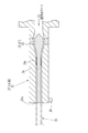
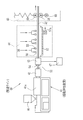
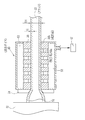
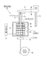
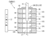
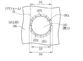
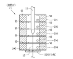
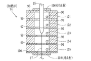
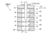
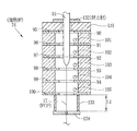
本発明のプラスチック光ファイバの製造装置は、プラスチック光ファイバ母材を加熱炉で加熱溶融延伸してプラスチック光ファイバを製造するプラスチック光ファイバの製造装置において、前記加熱炉が3段以上の独立して温度制御可能なヒータユニットから構成され、前記ヒータユニット間にオリフィスを挿入して各ヒータユニットを区画し、前記加熱炉の上部または下部の少なくともいずれかに前記加熱炉内への気体の流入を防止する封止材を設けた前記加熱炉内における気体の移動を制限する構造を有する。前記加熱炉上部に設けられる封止材は、前記プラスチック光ファイバ母材が貫通する円形の開口を備え、前記開口の直径D3(mm)が、前記プラスチック光ファイバ母材の直径D1(mm)に対して、1×D1(mm)<D3(mm)≦1.5×D1(mm)の範囲であることが好ましい。前記加熱炉上部に設けられる封止材は、前記プラスチック光ファイバ母材が貫通する円形の開口を備え、前記開口の直径D3(mm)が、前記プラスチック光ファイバ母材の直径D1(mm)に対して、0.75×D1(mm)≦D3(mm)≦1×D1(mm)の範囲であり、前記封止材の一部が前記プラスチック光ファイバ母材の外周面を覆うことが好ましい。 The plastic optical fiber manufacturing apparatus of the present invention is a plastic optical fiber manufacturing apparatus that manufactures a plastic optical fiber by heating, melting and stretching a plastic optical fiber base material in a heating furnace. It is composed of heater units that can be controlled in temperature, and each heater unit is partitioned by inserting an orifice between the heater units to prevent gas from flowing into the heating furnace to at least one of the upper part and the lower part of the heating furnace. The structure which restrict | limits the movement of the gas in the said heating furnace provided with the sealing material to perform is provided. The sealing material provided in the upper part of the heating furnace includes a circular opening through which the plastic optical fiber preform passes, and the diameter D3 (mm) of the opening is equal to the diameter D1 (mm) of the plastic optical fiber preform. On the other hand, the range of 1 × D1 (mm) <D3 (mm) ≦ 1.5 × D1 (mm) is preferable. The sealing material provided in the upper part of the heating furnace includes a circular opening through which the plastic optical fiber preform passes, and the diameter D3 (mm) of the opening is equal to the diameter D1 (mm) of the plastic optical fiber preform. On the other hand, it is in the range of 0.75 × D1 (mm) ≦ D3 (mm) ≦ 1 × D1 (mm), and it is preferable that a part of the sealing material covers the outer peripheral surface of the plastic optical fiber preform. .
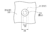
前記加熱炉下部に設けられる封止材は、前記プラスチック光ファイバが通過する円形の開口を備え、前記開口の直径D6(mm)が、前記プラスチック光ファイバの外径D5(mm)に対して、1.2×D5(mm)≦D6(mm)≦10×D5(mm)の範囲であることが好ましい。前記加熱炉内にヘリウム,アルゴン,窒素のうち少なくとも1つの気体を供給する気体供給手段を備えることが好ましい。 The sealing material provided in the lower part of the heating furnace includes a circular opening through which the plastic optical fiber passes, and the diameter D6 (mm) of the opening is smaller than the outer diameter D5 (mm) of the plastic optical fiber. It is preferable that the range is 1.2 × D5 (mm) ≦ D6 (mm) ≦ 10 × D5 (mm). It is preferable that a gas supply means for supplying at least one gas of helium, argon, and nitrogen is provided in the heating furnace.
本発明のプラスチック光ファイバの製造方法は、プラスチック光ファイバ母材を加熱炉で加熱溶融延伸し、プラスチック光ファイバとするプラスチック光ファイバの製造方法において、前記加熱炉が多段の独立して温度制御可能なヒータユニットから構成され、前記ヒータユニット間にオリフィスを挿入して区画としたものを用い、前記加熱炉の上部または下部の少なくともいずれかに前記加熱炉内に大気の流入を防止する封止材を設け、前記各区画内の温度変動を設定温度±0.5℃以内とし、前記プラスチック光ファイバ母材を加熱溶融延伸してプラスチック光ファイバを製造する。なお、前記各区画内の温度変動は、設定温度±0.3℃以内がより好ましく、最も好ましくは設定温度±0.2℃以内とすることである。 The plastic optical fiber manufacturing method of the present invention is a method of manufacturing a plastic optical fiber in which a plastic optical fiber preform is heated and melted and stretched in a heating furnace to form a plastic optical fiber. A sealing material that is composed of a heater unit and uses an orifice inserted between the heater units to form a partition, and prevents air from flowing into the heating furnace at least in either the upper part or the lower part of the heating furnace The temperature fluctuation in each section is set within a set temperature ± 0.5 ° C., and the plastic optical fiber preform is heated, melted and stretched to produce a plastic optical fiber. The temperature fluctuation in each section is more preferably set temperature ± 0.3 ° C. or less, most preferably set temperature ± 0.2 ° C. or less.
本発明のプラスチック光ファイバの製造装置及び製造方法によれば、プラスチック光ファイバ母材を加熱炉で加熱溶融延伸し、プラスチック光ファイバとするプラスチック光ファイバの製造装置及び製造方法において、前記加熱炉が多段の独立して温度制御可能なヒータユニットから構成され、前記ヒータユニット間にオリフィスを挿入して各区画としたものを用い、前記加熱炉の上部または下部の少なくともいずれかに前記加熱炉内に大気の流入を防止する封止材を設け、前記各区画内の温度変動を設定温度±0.5℃以内とし、前記プラスチック光ファイバ母材を加熱溶融延伸してプラスチック光ファイバを製造するから、加熱炉を封止して、炉内温度の変動を抑えることで、外径変動が小さいプラスチック光ファイバを得ることができる。 According to the plastic optical fiber manufacturing apparatus and manufacturing method of the present invention, in the plastic optical fiber manufacturing apparatus and manufacturing method, a plastic optical fiber preform is heated and melted and stretched in a heating furnace to form a plastic optical fiber. It is composed of multi-stage independent temperature controllable heater units, and each section is formed by inserting an orifice between the heater units. At least one of the upper part and the lower part of the heating furnace is provided in the heating furnace. Since a sealing material for preventing the inflow of air is provided, the temperature fluctuation in each section is set within a set temperature ± 0.5 ° C., and the plastic optical fiber preform is heated and melt-stretched to produce a plastic optical fiber. By sealing the heating furnace and suppressing fluctuations in the furnace temperature, it is possible to obtain a plastic optical fiber with small fluctuations in the outer diameter. .
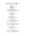
本発明に係るプラスチック光ファイバは、コア部とクラッド部のいずれもがポリマーから形成されている。なお、コア部とクラッド部とからのみなるものをPOF(プラスチック光ファイバ)と称する。本発明に係るPOFの製造方法を図1に示す。クラッドパイプ作製工程11で原料ポリマーを溶融押出法によりクラッドパイプ12を作製する。なお、クラッドパイプ12の製造方法については、後に詳細に説明する。次に、アウターコア重合工程13において、クラッドパイプ12の内周面にアウターコア20a(図5参照)を形成する。重合性組成物を含むアウターコア液形成用液(以下、アウターコア液と称する)を調製し、その液をクラッドパイプ12内に入れてアウターコア重合を行う。そして、インナーコア重合工程14でアウターコア20a内にインナーコア20b(図5参照)を形成する。インナーコア形成用液(以下、インナーコア液と称する)を調製し、そのインナーコア液をアウターコア20aが形成されたクラッドパイプ12内に入れて、インナーコア重合を行いインナーコア20b(図5参照)を形成する。これらアウターコア20aとインナーコア20bとによりコア部20が形成されてプリフォーム15が得られる。
In the plastic optical fiber according to the present invention, both the core part and the clad part are formed of a polymer. In addition, what consists only of a core part and a clad part is called POF (plastic optical fiber). A method for producing POF according to the present invention is shown in FIG. In the clad
プリフォーム15を延伸工程16により、加熱溶融延伸してPOF17とする。なお、この延伸工程16については後に詳細に説明する。POF17は、そのままの形態で光伝送体として用いることができる。しかしながら、取り扱いを容易にしたりPOF17の外周面の損傷を抑制したりするために被覆層を形成することが好ましい。被覆層は、被覆工程18により形成し、POF17の外周面に被覆材が被覆層として形成されたプラスチック光ファイバ心線(プラスチック光ファイバコードとも称される。以下、光ファイバ心線と称する)19が得られる。
The
(コア部)
コア部の原料の重合性モノマーとしては、塊状重合が容易である原料を選択するのが好ましい。光透過性が高く塊状重合しやすい原料としては例えば、以下のような(メタ)アクリル酸エステル類(フッ素不含(メタ)アクリル酸エステル(a),含フッ素(メタ)アクリル酸エステル(b)),スチレン系化合物(c),ビニルエステル類(d)等を例示することができ、コア部はこれらのホモポリマー、あるいはこれらモノマーの2種以上からなる共重合体、およびホモポリマー及び/または共重合体の混合物から形成することができる。これらのうち、(メタ)アクリル酸エステル類を重合性モノマーとして含む組成を好ましく用いることができる。
(Core part)
As the polymerizable monomer for the raw material of the core part, it is preferable to select a raw material that can be easily bulk-polymerized. Examples of raw materials that are highly light transmissive and easy to bulk polymerize include the following (meth) acrylic acid esters (fluorine-free (meth) acrylic acid ester (a), fluorine-containing (meth) acrylic acid ester (b) ), Styrenic compounds (c), vinyl esters (d), etc., and the core part is a homopolymer of these, or a copolymer comprising two or more of these monomers, and a homopolymer and / or It can be formed from a mixture of copolymers. Among these, a composition containing (meth) acrylic acid esters as a polymerizable monomer can be preferably used.
以上に挙げた重合性モノマーとして具体的に、(a)フッ素不含メタクリル酸エステルおよびフッ素不含アクリル酸エステルとしては、メタクリル酸メチル(MMA)、メタクリル酸エチル、メタクリル酸イソプロピル、メタクリル酸−tert−ブチル、メタクリル酸ベンジル(BzMA)、メタクリル酸フェニル、メタクリル酸シクロヘキシル、メタクリル酸ジフェニルメチル、トリシクロ[5・2・1・02,6 ]デカニルメタクリレート、アダマンチルメタクリレート、イソボルニルメタクリレート、ノルボルニルメタクリレート等が挙げられ、アクリル酸メチル、アクリル酸エチル、アクリル酸−tert−ブチル、アクリル酸フェニル等が挙げられる。また、(b)含フッ素アクリル酸エステルおよび含フッ素メタクリル酸エステルとしては、2,2,2 −トリフルオロエチルメタクリレート、2,2,3,3 −テトラフルオロプロピルメタクリレート、2,2,3,3,3 −ペンタフルオロプロピルメタクリレート、1 −トリフルオロメチル−2,2,2 −トリフルオロエチルメタクリレート、2,2,3,3,4,4,5,5 −オクタフルオロペンチルメタクリレート、2,2,3,3,4,4 −ヘキサフルオロブチルメタクリレート等が挙げられる。さらに、(c)スチレン系化合物としては、スチレン、α−メチルスチレン、クロロスチレン、ブロモスチレン等が挙げられる。さらには、(d)ビニルエステル類としては、ビニルアセテート、ビニルベンゾエート、ビニルフェニルアセテート、ビニルクロロアセテート等が挙げられる。勿論、これらに限定されるものではない。モノマーの単独あるいは共重合体からなるコア部のポリマーの屈折率は、クラッド部のそれに比べて同等かあるいはそれ以上になるように構成モノマーの種類,組成比を選択する。特に好ましいポリマーとしては、透明樹脂であるポリメタクリル酸メチル(PMMA)が挙げられる。 Specific examples of the polymerizable monomers listed above include (a) fluorine-free methacrylic acid ester and fluorine-free acrylic acid ester: methyl methacrylate (MMA), ethyl methacrylate, isopropyl methacrylate, methacrylic acid-tert - butyl, phenyl methacrylate benzyl (BzMA), methacrylate, cyclohexyl methacrylate, diphenylmethyl, tricyclo [5 · 2 · 1 · 0 2,6] decanyl methacrylate, adamantyl methacrylate, isobornyl methacrylate, norbornene Nyl methacrylate and the like, and methyl acrylate, ethyl acrylate, tert-butyl acrylate, phenyl acrylate, and the like. In addition, (b) fluorine-containing acrylic acid ester and fluorine-containing methacrylate ester include 2,2,2-trifluoroethyl methacrylate, 2,2,3,3-tetrafluoropropyl methacrylate, 2,2,3,3 , 3-Pentafluoropropyl methacrylate, 1-trifluoromethyl-2,2,2-trifluoroethyl methacrylate, 2,2,3,3,4,4,5,5-octafluoropentyl methacrylate, 2,2, 3,3,4,4-hexafluorobutyl methacrylate and the like. Furthermore, (c) styrene compounds include styrene, α-methylstyrene, chlorostyrene, bromostyrene, and the like. Furthermore, (d) vinyl esters include vinyl acetate, vinyl benzoate, vinyl phenyl acetate, vinyl chloroacetate and the like. Of course, it is not limited to these. The type and composition ratio of the constituent monomers are selected so that the refractive index of the polymer of the core portion made of a monomer alone or a copolymer is equal to or higher than that of the cladding portion. A particularly preferred polymer is polymethyl methacrylate (PMMA), which is a transparent resin.
さらに、作製するPOF17を近赤外線用途に用いる場合は、コア部のポリマーを構成するC−H結合に起因した吸収損失が起こるために、特許第3332922号公報などに記載されているような重水素化ポリメチルメタクリレート(PMMA−d8)、ポリトリフルオロエチルメタクリレート(P3FMA)、ポリヘキサフルオロイソプロピル2−フルオロアクリレート(HFIP 2−FA)などを始めとする、C−H結合の水素原子(H)を重水素原子(D)やフッ素(F)などで置換した重合体を用いることで、この伝送損失を生じる波長域を長波長化することができ、伝送信号光の損失を軽減することができる。なお、原料モノマーは重合後の透明性を損なわないためにも、不純物や散乱源となる異物は重合前に十分に低減することが望ましい。
Further, when the
(クラッド部)
クラッド部の素材には、コア部を伝送する光がそれらの界面で全反射するために、コア部の屈折率より低い屈折率を有し、コア部との密着性が良いものを好ましく用いることができる。ただし、素材の選択によってコア部とクラッド部の界面の不整が起こりやすい、もしくは製造適性上好ましくない場合などにおいては、コア部とクラッド部の間にさらに層を設けても良い。例えば、コア部との界面(即ち、中空管の内壁面)に、コア部のマトリックスと同一組成のポリマーからなるアウターコア層を形成することにより、コア部とクラッド部との界面状態を矯正することができる。アウターコア層の詳細については後述する。勿論、アウターコア層を形成せずに、クラッド部そのものを、コア部のマトリックスと同一組成のポリマーから形成することもできる。
(Clad part)
For the material of the clad part, it is preferable to use a material having a refractive index lower than the refractive index of the core part and having good adhesion to the core part because the light transmitted through the core part is totally reflected at the interface between them. Can do. However, in the case where irregularity of the interface between the core part and the clad part is likely to occur due to selection of the material or it is not preferable in terms of manufacturing suitability, a layer may be further provided between the core part and the clad part. For example, by forming an outer core layer made of a polymer having the same composition as the matrix of the core part at the interface with the core part (that is, the inner wall surface of the hollow tube), the interface state between the core part and the cladding part is corrected. can do. Details of the outer core layer will be described later. Of course, without forming the outer core layer, the cladding part itself can be formed of a polymer having the same composition as the matrix of the core part.
クラッド部の素材としては、タフネスに優れ、耐湿熱性にも優れているものが好ましく用いられる。例えば、フッ素含有モノマーの単独重合体または共重合体からなるのが好ましい。フッ素含有モノマーとしてはフッ化ビニリデン(PVDF)が好ましく、フッ化ビニリデンを10質量%以上含有する1種以上の重合性モノマーを重合させて得られるフッ素樹脂が好ましく用いることができる。 As the material for the clad part, a material excellent in toughness and heat and heat resistance is preferably used. For example, it preferably comprises a homopolymer or copolymer of a fluorine-containing monomer. As the fluorine-containing monomer, vinylidene fluoride (PVDF) is preferable, and a fluororesin obtained by polymerizing one or more polymerizable monomers containing 10% by mass or more of vinylidene fluoride can be preferably used.
また、後述の溶融押出法により重合体を成形し、クラッド部を作製する場合は、重合体の溶融粘度が適当であることが必要である。この溶融粘度については、相関する物性として分子量が用いられ特に重量平均分子量との相関がある。本発明においては、重量平均分子量が1万〜100万の範囲であることが適当であり、より好ましくは5万〜50万の範囲である。 Moreover, when forming a clad part by shape | molding a polymer with the below-mentioned melt extrusion method, it is necessary for the melt viscosity of a polymer to be suitable. As for the melt viscosity, the molecular weight is used as a correlated physical property, and particularly has a correlation with the weight average molecular weight. In the present invention, the weight average molecular weight is suitably in the range of 10,000 to 1,000,000, more preferably in the range of 50,000 to 500,000.
さらに、できるだけコア部へ水分が浸入することを防ぐことが好ましい。そのためには、吸水率が低いポリマーをクラッド部の素材(材料)として用いる。すなわち飽和吸水率(以下、吸水率と称する)が1.8%未満のポリマーを用いてクラッド部を作製するのが好ましい。より好ましくは1.5%未満のポリマー、さらに好ましくは1.0%未満のポリマーを用いてクラッド部を作製することが好ましい。また、前記アウターコア層を作製する場合にも同様の吸水率のポリマーを用いることが好ましい。吸水率(%)は、ASTM D 570試験法に従い、23℃の水中に試験片を1週間浸漬し、そのときの吸水率を測定することにより算出することができる。 Furthermore, it is preferable to prevent moisture from entering the core as much as possible. For this purpose, a polymer having a low water absorption rate is used as a material (material) for the cladding. That is, it is preferable to produce a clad part using a polymer having a saturated water absorption rate (hereinafter referred to as a water absorption rate) of less than 1.8%. More preferably, the clad portion is formed using less than 1.5% polymer, and more preferably less than 1.0% polymer. Further, it is preferable to use a polymer having the same water absorption rate when the outer core layer is produced. The water absorption rate (%) can be calculated by immersing the test piece in water at 23 ° C. for 1 week according to the ASTM D 570 test method and measuring the water absorption rate at that time.
(重合開始剤)
前記コア部及び/又はクラッド部が、重合性モノマーから重合されたポリマーから作製される場合、重合の際に重合開始剤が用いられる。重合開始剤としては、用いるモノマーや重合方法に応じて適宜選択することができ、例えば、過酸化ベンゾイル(BPO)、tert−ブチルパーオキシ−2−エチルヘキサネート(PBO)、ジ−tert−ブチルパーオキシド(PBD)、tert−ブチルパーオキシイソプロピルカーボネート(PBI)、n−ブチル−4,4−ビス(tert−ブチルパーオキシ)バラレート(PHV)などのパーオキサイド系化合物が挙げられる。また、2,2’−アゾビスイソブチロニトリル、2,2’−アゾビス(2−メチルブチロニトリル)、1,1’−アゾビス(シクロヘキサン−1−カルボニトリル)、2,2’−アゾビス(2−メチルプロパン)、2,2’−アゾビス(2−メチルブタン)、2,2’−アゾビス(2−メチルペンタン)、2,2’−アゾビス(2,3−ジメチルブタン)、2,2’−アゾビス(2−メチルヘキサン)、2,2’−アゾビス(2,4−ジメチルペンタン)、2,2’−アゾビス(2,3,3−トリメチルブタン)、2,2’−アゾビス(2,4,4−トリメチルペンタン)、3,3’−アゾビス(3−メチルペンタン)、3,3’−アゾビス(3−メチルヘキサン)、3,3’−アゾビス(3,4−ジメチルペンタン)、3,3’−アゾビス(3−エチルペンタン)、ジメチル−2,2’−アゾビス(2−メチルプロピオネート)、ジエチル−2,2’−アゾビス(2−メチルプロピオネート)、ジ−tert−ブチル−2,2’−アゾビス(2−メチルプロピオネート)などのアゾ系化合物が挙げられる。なお、重合開始剤は勿論これらに限定されるものではなく、更には2種類以上を併用してもよい。
(Polymerization initiator)
When the core part and / or the clad part are made from a polymer polymerized from a polymerizable monomer, a polymerization initiator is used in the polymerization. As a polymerization initiator, it can select suitably according to the monomer and polymerization method to be used, for example, benzoyl peroxide (BPO), tert- butyl peroxy-2-ethyl hexanate (PBO), di-tert-butyl. Examples thereof include peroxide compounds such as peroxide (PBD), tert-butyl peroxyisopropyl carbonate (PBI), and n-butyl-4,4-bis (tert-butylperoxy) valerate (PHV). 2,2′-azobisisobutyronitrile, 2,2′-azobis (2-methylbutyronitrile), 1,1′-azobis (cyclohexane-1-carbonitrile), 2,2′-azobis (2-methylpropane), 2,2′-azobis (2-methylbutane), 2,2′-azobis (2-methylpentane), 2,2′-azobis (2,3-dimethylbutane), 2,2 '-Azobis (2-methylhexane), 2,2'-azobis (2,4-dimethylpentane), 2,2'-azobis (2,3,3-trimethylbutane), 2,2'-azobis (2 , 4,4-trimethylpentane), 3,3′-azobis (3-methylpentane), 3,3′-azobis (3-methylhexane), 3,3′-azobis (3,4-dimethylpentane), 3,3′-azobis (3-ethylpentane , Dimethyl-2,2′-azobis (2-methylpropionate), diethyl-2,2′-azobis (2-methylpropionate), di-tert-butyl-2,2′-azobis (2- And azo compounds such as methyl propionate). Of course, the polymerization initiator is not limited to these, and two or more kinds may be used in combination.
(連鎖移動剤)
コア部形成用重合性組成物及びクラッド部形成用重合性組成物は、連鎖移動剤を含有していることが好ましい。前記連鎖移動剤は、主に重合体の分子量を調整するために用いられる。前記クラッド部およびコア部形成用重合性組成物がそれぞれ連鎖移動剤を含有していると、重合性モノマーからポリマーを形成する際に、重合速度および重合度を前記連鎖移動剤によってより制御することができ、重合体の分子量を所望の分子量に調整することができる。例えば、得られたプリフォームを延伸により線引してPOFとする際に、分子量を調整することによって延伸時における機械的特性を所望の範囲とすることができ、生産性の向上にも寄与する。
(Chain transfer agent)
The polymerizable composition for forming a core part and the polymerizable composition for forming a clad part preferably contain a chain transfer agent. The chain transfer agent is mainly used for adjusting the molecular weight of the polymer. When the polymerizable composition for forming the clad part and the core part contains a chain transfer agent, when the polymer is formed from the polymerizable monomer, the polymerization rate and the degree of polymerization are more controlled by the chain transfer agent. And the molecular weight of the polymer can be adjusted to a desired molecular weight. For example, when the obtained preform is drawn by drawing to make POF, the mechanical properties at the time of drawing can be adjusted to a desired range by adjusting the molecular weight, which contributes to improvement of productivity. .
前記連鎖移動剤については、併用する重合性モノマーの種類に応じて、適宜、種類および添加量を選択できる。各モノマーに対する連鎖移動剤の連鎖移動定数は、例えば、ポリマーハンドブック第3版(J.BRANDRUPおよびE.H.IMMERGUT編、JOHN WILEY&SON発行)を参照することができる。また、前記連鎖移動定数は大津隆行、木下雅悦共著「高分子合成の実験法」化学同人、昭和47年刊を参考にして、実験によっても求めることができる。 About the said chain transfer agent, according to the kind of polymerizable monomer used together, a kind and addition amount can be selected suitably. The chain transfer constant of the chain transfer agent for each monomer can be referred to, for example, Polymer Handbook 3rd edition (edited by J. BRANDRUP and EH IMMERGUT, published by JOHN WILEY & SON). The chain transfer constant can also be obtained by experiment with reference to Takayuki Otsu and Masato Kinoshita, “Experimental Methods for Polymer Synthesis”, Kagaku Dojin, published in 1972.
連鎖移動剤としては、アルキルメルカプタン類(例えば、n−ブチルメルカプタン、n−ペンチルメルカプタン、n−オクチルメルカプタン、n−ラウリルメルカプタン、tert−ドデシルメルカプタンなど)、チオフェノール類(例えば、チオフェノール、m−ブロモチオフェノール、p−ブロモチオフェノール、m−トルエンチオール、p−トルエンチオールなど)などを用いることが好ましい。特に、n−オクチルメルカプタン、n−ラウリルメルカプタン、tert−ドデシルメルカプタンのアルキルメルカプタンを用いるのが好ましい。また、C−H結合の水素原子が重水素原子(D)やフッ素原子(F)で置換された連鎖移動剤を用いることもできる。なお、連鎖移動剤は勿論これらに限定されるものではなく、これら連鎖移動剤は2種類以上を併用してもよい。 Examples of the chain transfer agent include alkyl mercaptans (eg, n-butyl mercaptan, n-pentyl mercaptan, n-octyl mercaptan, n-lauryl mercaptan, tert-dodecyl mercaptan), thiophenols (eg, thiophenol, m- Bromothiophenol, p-bromothiophenol, m-toluenethiol, p-toluenethiol, etc.) are preferably used. In particular, it is preferable to use an alkyl mercaptan such as n-octyl mercaptan, n-lauryl mercaptan, and tert-dodecyl mercaptan. A chain transfer agent in which a hydrogen atom of a C—H bond is substituted with a deuterium atom (D) or a fluorine atom (F) can also be used. Of course, the chain transfer agent is not limited to these, and two or more of these chain transfer agents may be used in combination.
(屈折率調整剤)
前記コア部用重合性組成物に屈折率調整剤を含有させるのが好ましい。なお、場合によっては、クラッド部重合性組成物に屈折率調整剤を含有させても良い。屈折率調整剤の濃度に分布を持たせることによって、前記濃度の分布に基づいて屈折率分布型のコアを容易に作製することができる。屈折率調整剤を用いなくとも、コア部の形成に2種以上の重合性モノマーを用い、コア部内に共重合比の分布を持たせることによって、屈折率分布構造を導入することもできるが、共重合の組成比制御などと比較して、製造の簡便さなどを鑑みると屈折率調整剤を用いることが好ましい。
(Refractive index modifier)
It is preferable to add a refractive index adjusting agent to the polymerizable composition for the core part. In some cases, the clad part polymerizable composition may contain a refractive index adjusting agent. By providing a distribution of the concentration of the refractive index adjusting agent, a refractive index distribution type core can be easily produced based on the concentration distribution. Even without using a refractive index adjusting agent, it is possible to introduce a refractive index distribution structure by using two or more polymerizable monomers for forming the core portion and having a distribution of the copolymerization ratio in the core portion. It is preferable to use a refractive index adjusting agent in view of the ease of production and the like as compared with the composition ratio control of copolymerization.
屈折率調整剤はドーパントとも称し、併用する前記重合性モノマーの屈折率と異なる化合物である。その屈折率差は0.005以上であるのが好ましい。ドーパントは、これを含有する重合体が無添加の重合体と比較して、屈折率が高くなる性質を有する。これらは、特許第3332922号公報や特開平5−173026号公報に記載されているような、モノマーの合成によって生成される重合体との比較において溶解性パラメータとの差が7(cal/cm3 )1/2 以内であると共に、屈折率の差が0.001以上であり、これを含有する重合体が無添加の重合体と比較して屈折率が変化する性質を有し、重合体と安定して共存可能で、且つ前述の原料である重合性モノマーの重合条件(加熱および加圧等の重合条件)下において安定であるものを、いずれも用いることができる。 The refractive index adjusting agent is also called a dopant, and is a compound different from the refractive index of the polymerizable monomer used together. The refractive index difference is preferably 0.005 or more. The dopant has the property that the polymer containing it has a higher refractive index than the additive-free polymer. These have a difference in solubility parameter of 7 (cal / cm 3) in comparison with a polymer produced by monomer synthesis as described in Japanese Patent No. 3333292 and Japanese Patent Laid-Open No. 5-173026. ) Within 1/2 , and the difference in refractive index is 0.001 or more, and the polymer containing this has the property of changing the refractive index as compared to the additive-free polymer. Any of those which can stably coexist and are stable under the polymerization conditions (polymerization conditions such as heating and pressurization) of the polymerizable monomer which is the above-mentioned raw material can be used.
上記性質を有し、重合体と安定して共存可能で、且つ前述の原料である重合性モノマーの重合条件(加熱および加圧等の重合条件)下において安定であるものを、ドーパントとして用いることができる。本実施形態では、コア部形成用重合性組成物にドーパントを含有させ、コア部を形成する工程において界面ゲル重合法により重合の進行方向を制御し、ドーパントの濃度に傾斜を持たせ、コア部にドーパントの濃度分布に基づく屈折率分布構造を形成する方法を例示する。このように、屈折率の分布を有するコア部を「屈折率分布型コア部」と称する。屈折率分布型コア部を形成することにより、得られる光学部材は広い伝送帯域を有する屈折率分布型プラスチック光ファイバ(GI型POF)となる。 Using the above-mentioned properties as a dopant that can stably coexist with the polymer and is stable under the polymerization conditions (polymerization conditions such as heating and pressurization) of the above-described raw material polymerizable monomer. Can do. In the present embodiment, the core portion-forming polymerizable composition contains a dopant, and in the step of forming the core portion, the progress of polymerization is controlled by the interfacial gel polymerization method, and the concentration of the dopant is given a gradient. A method for forming a refractive index distribution structure based on the dopant concentration distribution is illustrated below. In this way, the core portion having the refractive index distribution is referred to as a “refractive index distribution type core portion”. By forming the gradient index core part, the obtained optical member becomes a gradient index plastic optical fiber (GI POF) having a wide transmission band.
ドーパントは重合性化合物であってもよく、重合性化合物のドーパントを用いた場合は、これを共重合成分として含む共重合体がこれを含まない重合体と比較して、屈折率が上昇する性質を有するものを用いる。なお、このような共重合体には、MMA−BzMA共重合体などが挙げられる。 The dopant may be a polymerizable compound. When a dopant of the polymerizable compound is used, the copolymer containing this as a copolymerization component has a property of increasing the refractive index as compared with a polymer not containing the copolymer. Use what has. Examples of such a copolymer include MMA-BzMA copolymer.
前記ドーパントとしては、特許第3332922号や特開平11−142657号公報に記載されている様な、例えば、安息香酸ベンジル(BEN)、硫化ジフェニル(DPS)、リン酸トリフェニル(TPP)、フタル酸ベンジル−n−ブチル(BBP)、フタル酸ジフェニル(DPP)、ジフェニル(DP)、ジフェニルメタン(DPM)、リン酸トリクレジル(TCP)、ジフェニルスルホキシド(DPSO)、硫化ジフェニル誘導体、ジチアン誘導体などが挙げられる。中でも、BEN、DPS、TPP、DPSOおよび硫化ジフェニル誘導体、ジチアン誘導体が好ましい。なお、これらの化合物中に存在する水素原子を重水素原子に置換した化合物も広い波長域での透明性を向上させる目的で用いることができる。また、重合性化合物として、例えば、トリブロモフェニルメタクリレート等が挙げられる。屈折率調整成分として重合性化合物を用いる場合は、マトリックスを形成する際に、重合性モノマーと重合性屈折率成分とを共重合させるので、種々の特性(特に光学特性)の制御がより困難となるが、耐熱性の面では有利となる可能性がある。 Examples of the dopant include benzyl benzoate (BEN), diphenyl sulfide (DPS), triphenyl phosphate (TPP), and phthalic acid as described in Japanese Patent No. 3332922 and JP-A-11-142657. Examples include benzyl-n-butyl (BBP), diphenyl phthalate (DPP), diphenyl (DP), diphenylmethane (DPM), tricresyl phosphate (TCP), diphenyl sulfoxide (DPSO), diphenyl sulfide derivatives, and dithian derivatives. Among them, BEN, DPS, TPP, DPSO, sulfurized diphenyl derivatives, and dithian derivatives are preferable. In addition, compounds obtained by substituting hydrogen atoms present in these compounds with deuterium atoms can also be used for the purpose of improving transparency in a wide wavelength region. Examples of the polymerizable compound include tribromophenyl methacrylate. When a polymerizable compound is used as the refractive index adjusting component, it is difficult to control various characteristics (particularly optical characteristics) because the polymerizable monomer and the polymerizable refractive index component are copolymerized when forming the matrix. However, it may be advantageous in terms of heat resistance.
屈折率調整剤の濃度および分布を調整することによって、光学部材であるPOFの屈折率を所望の値に変化させることができる。その添加量は、用途および組み合わされる部材に応じて適宜選ばれる。屈折率調整剤は、複数種類添加してもよい。 By adjusting the concentration and distribution of the refractive index adjusting agent, the refractive index of the POF that is the optical member can be changed to a desired value. The amount added is appropriately selected according to the use and the member to be combined. A plurality of types of refractive index adjusting agents may be added.
(その他の添加剤)
その他、コア部、クラッド部もしくはそれらの一部には、光伝送性能を低下させない範囲で、それらを作製する重合性組成物にその他の添加剤を添加することができる。例えば、コア部もしくはその一部に耐候性や耐久性などを向上させる目的で、安定剤を添加することができる。また、光伝送性能の向上を目的として、光信号増幅用の誘導放出機能化合物を添加することもできる。前記誘導放出機能化合物を添加することにより、減衰した信号光を励起光により増幅することができ、伝送距離が向上するので、例えば、光伝送リンクの一部に光ファイバ増幅器として使用することができる。これらの添加剤も、前記原料モノマーに添加した後、重合することによって、コア部、クラッド部もしくはそれらの一部に含有させることができる。
(Other additives)
In addition, other additives can be added to the polymerizable composition for producing them in the core part, the clad part, or a part thereof, as long as the optical transmission performance is not deteriorated. For example, a stabilizer can be added to the core portion or a part thereof for the purpose of improving weather resistance, durability and the like. In addition, for the purpose of improving optical transmission performance, a stimulated emission functional compound for optical signal amplification can also be added. By adding the stimulated emission functional compound, the attenuated signal light can be amplified by the excitation light, and the transmission distance is improved. For example, it can be used as an optical fiber amplifier in a part of the optical transmission link. . These additives can also be contained in the core part, the clad part, or a part of them by adding to the raw material monomer and then polymerizing.
(プリフォーム製造方法の説明)
以下に、本発明の製造方法を、コア部とクラッド部とを有する屈折率分布型プラスチック母材の製造方法に適用した実施の形態について説明する。本実施形態は、主として2種類あるが、以下の実施形態に限定されるわけではない。
(Description of preform manufacturing method)
Hereinafter, an embodiment in which the manufacturing method of the present invention is applied to a manufacturing method of a gradient index plastic preform having a core portion and a cladding portion will be described. Although there are mainly two types of this embodiment, it is not limited to the following embodiments.
まず、第1の実施形態は、クラッド部用重合性組成物を重合して中空管を作製する。または熱可塑性樹脂を溶融押し出し成形してクラッド部となる中空円筒管を作製する(第1工程)。前記中空円筒管の中空部でコア部形成用重合性組成物を界面ゲル重合させることによりコア部となる領域を形成し、コア部およびクラッド部に各々対応する領域からなるプリフォームを作製する(第2工程)。そして得られたプリフォームを本発明に係る製造装置及び製造方法により所望の形態に加工(第3工程)してPOFを得る。 First, in the first embodiment, a hollow tube is produced by polymerizing a polymerizable composition for a cladding part. Alternatively, a hollow cylindrical tube serving as a clad portion is produced by melt extrusion molding of a thermoplastic resin (first step). The core portion-forming polymerizable composition is subjected to interfacial gel polymerization in the hollow portion of the hollow cylindrical tube to form a region that becomes a core portion, and a preform that includes regions corresponding respectively to the core portion and the cladding portion is produced ( Second step). The obtained preform is processed into a desired form (third step) by the manufacturing apparatus and the manufacturing method according to the present invention to obtain POF.
次に、第2の実施形態は、第1の実施形態でクラッド部に相当する中空円筒管を形成した後にその内周面にさらにアウターコア部という層を形成する(第1’工程)。なお、このアウターコア層を有する形態においては中心のコア部はインナーコア部とも称される。以下の説明において、態様によって「コア部」という場合は「インナーコア部」の意味も兼ねる。 Next, in the second embodiment, after forming the hollow cylindrical tube corresponding to the clad portion in the first embodiment, a layer called an outer core portion is further formed on the inner peripheral surface (first step). In the form having the outer core layer, the central core portion is also referred to as an inner core portion. In the following description, the term “core part” also means the “inner core part” depending on the form.
例えば、ポリフッ化ビニリデン樹脂のような含フッ素樹脂からなる中空円筒管の中空部で、アウターコア用重合性組成物を回転重合法による重合などで、前記中空円筒管の内周面にアウターコア層を形成し、2層からなる中空円筒管を作製する(第1’工程)。前記中空円筒管の中空部にさらにインナーコア部を形成する。インナーコア部は、インナーコア部形成用重合性組成物を界面ゲル重合させて形成する(第2’工程)。そして、得られたプリフォームを所望の形態に加工(第3工程)して光学部材であるPOFを得る。 For example, in the hollow part of a hollow cylindrical tube made of a fluorine-containing resin such as polyvinylidene fluoride resin, the outer core layer is formed on the inner peripheral surface of the hollow cylindrical tube by polymerization of the polymerizable composition for the outer core by a rotational polymerization method. To form a hollow cylindrical tube having two layers (first 'step). An inner core portion is further formed in the hollow portion of the hollow cylindrical tube. The inner core portion is formed by interfacial gel polymerization of the polymerizable composition for forming the inner core portion (second step). Then, the obtained preform is processed into a desired form (third step) to obtain POF which is an optical member.
第2の実施形態においては、2層からなる同心の中空円筒管を作製する際、上記のように段階的でなく、クラッド部となるフッ素樹脂とアウターコア用重合組成物の重合体とを溶融共押し出しの方法の一段階で作製する方法なども容易に適用できる。 In the second embodiment, when producing a concentric hollow cylindrical tube composed of two layers, the fluororesin serving as the cladding portion and the polymer of the polymerization composition for the outer core are not melted stepwise as described above. A method of manufacturing in one step of the coextrusion method can be easily applied.
前記第1の実施の形態ではクラッド部/コア部形成用、第2の実施の形態ではアウターコア部/インナーコア部形成用の各々の重合性組成物に用いられる重合性モノマーの組成は、互いに等しいことが好ましい。ただし、その組成比については同一でなくてもよく、また副成分については等しくなくてもよい。等しい種類の重合性モノマーを用いることによって、クラッド部/コア部またはアウターコア部/インナーコア部界面における光透過性および接着性を向上させることができる。また、クラッド部あるいはアウターコア部を形成する樹脂が共重合体からなり、共重合成分の屈折率が異なる場合、共重合成分の比率を制御することでコア部との屈折率差を大きく持たせやすく、その結果、屈折率分布構造を形成し易くすることもできる。 In the first embodiment, the composition of the polymerizable monomers used in the polymerizable composition for forming the clad / core part and in the second embodiment for forming the outer core / inner core part is mutually different. Preferably equal. However, the composition ratio may not be the same, and the subcomponents may not be equal. By using the same type of polymerizable monomer, it is possible to improve light transmittance and adhesiveness at the cladding / core or outer core / inner core interface. In addition, when the resin forming the clad part or the outer core part is made of a copolymer and the refractive index of the copolymer component is different, the refractive index difference from the core part is increased by controlling the ratio of the copolymer component. As a result, the refractive index distribution structure can be easily formed.
第2の実施形態では、クラッド部とコア部との間にアウターコア部を形成することによって、クラッド部とコア部との材質の違いによる接着性の低下および生産性の低下などを軽減させる。その結果、クラッド部およびコア部に用いる材料の選択の幅を広げることができる。クラッド部に相当する円筒形状の管は、例えば、市販されているフッ素樹脂を溶融押出しや重合性組成物の回転重合により、所望の径と厚みのパイプに成形することで作製することもできる。さらに、得られたパイプの中空部で前記アウターコア部形成用重合性組成物を回転重合させ、その内周面にアウターコア層を形成することができる。また、その他、前記フッ素樹脂と前記重合性組成物からなる重合体を共押し出しすることによっても同様の構造体を作製することもできる。 In the second embodiment, by forming the outer core portion between the clad portion and the core portion, it is possible to reduce a decrease in adhesiveness and a decrease in productivity due to a difference in material between the clad portion and the core portion. As a result, the range of selection of materials used for the cladding part and the core part can be expanded. The cylindrical tube corresponding to the clad portion can be produced, for example, by molding a commercially available fluororesin into a pipe having a desired diameter and thickness by melt extrusion or rotational polymerization of a polymerizable composition. Furthermore, the outer core layer-forming polymerizable composition can be rotationally polymerized in the hollow portion of the obtained pipe to form an outer core layer on the inner peripheral surface thereof. In addition, a similar structure can be produced by co-extrusion of a polymer comprising the fluororesin and the polymerizable composition.
本発明に係るPOFを作製する際に、屈折率調整成分を用い、その濃度に傾斜を持たせることによっても、GI型POFを作製することができるが、他の形態のPOFにも本発明は適用できる。屈折率調整成分の濃度に傾斜を持たせる方法としては、後述する重合体へモノマーが含浸して膨潤・溶解することにより重合が進むゲル重合を行う界面ゲル重合法や円筒の軸を中心に回転させた円筒内で界面ゲル重合反応により形成する回転ゲル重合法などを適用することができる。 When producing a POF according to the present invention, a GI-type POF can also be produced by using a refractive index adjusting component and providing a gradient in its concentration. However, the present invention also applies to other forms of POF. Applicable. As a method of giving a gradient to the concentration of the refractive index adjusting component, an interfacial gel polymerization method in which polymerization proceeds as a polymer is impregnated and swelled / dissolved in a polymer, which will be described later, or rotated around a cylindrical axis A rotating gel polymerization method or the like formed by an interfacial gel polymerization reaction in a cylinder that has been allowed to be applied can be applied.
前記クラッド部、アウターコア部を重合性組成物で作製する場合およびコア部形成用重合性組成物において、各成分の含有割合の好ましい範囲は、その種類に応じて異なり一概に定めることはできないが、一般的には、重合開始剤は、重合性モノマーに対して0.005質量%〜0.5質量%であることが好ましく、0.01質量%〜0.5質量%であることがより好ましい。前記連鎖移動剤は、重合性モノマーに対して0.10質量%〜1.0質量%であることが好ましく、0.15質量%〜0.50質量%であることがより好ましい。また、前記屈折率調整成分は、重合性モノマーに対して1質量%〜30質量%であることが好ましく、1質量%〜25質量%であることがより好ましい。 In the case where the clad part and the outer core part are made of a polymerizable composition, and in the polymerizable composition for forming a core part, the preferred range of the content ratio of each component differs depending on the type and cannot be unconditionally determined. In general, the polymerization initiator is preferably 0.005% by mass to 0.5% by mass and more preferably 0.01% by mass to 0.5% by mass with respect to the polymerizable monomer. preferable. The chain transfer agent is preferably 0.10% by mass to 1.0% by mass with respect to the polymerizable monomer, and more preferably 0.15% by mass to 0.50% by mass. In addition, the refractive index adjusting component is preferably 1% by mass to 30% by mass and more preferably 1% by mass to 25% by mass with respect to the polymerizable monomer.
前記クラッド部、アウターコア部およびコア部形成用重合体組成物を重合することによって得られるポリマーの分子量は、プリフォームを延伸する関係から、重量平均分子量で1万〜100万の範囲であることが好ましく、3万〜50万であることがさらに好ましい。さらに延伸性の観点で分子量分布(MWD:重量平均分子量/数平均分子量)も影響する。MWDが大きくなると、極端に分子量が高い成分がわずかでもあると延伸性が悪くなり、場合によっては延伸できなくなることもある。したがって、好ましい範囲としては、MWDが4以下が好ましく、さらには3以下が好ましい。 The molecular weight of the polymer obtained by polymerizing the clad part, the outer core part, and the polymer composition for forming the core part is in the range of 10,000 to 1,000,000 in terms of weight average molecular weight, because the preform is stretched. Is preferable, and it is more preferable that it is 30,000 to 500,000. Further, the molecular weight distribution (MWD: weight average molecular weight / number average molecular weight) is also influenced from the viewpoint of stretchability. If the MWD becomes large, even if there are a few components having an extremely high molecular weight, the stretchability is deteriorated, and in some cases, stretching may not be possible. Therefore, as a preferable range, MWD is preferably 4 or less, and more preferably 3 or less.
次に、前記第1および第2の形態(特に前記第1の実施形態)の各工程について詳細に説明するが、以下に示す方法や順序に限定されるものではない。例えば、アウターコア形成後にインナーコアを作製したロッドにクラッドを塗布や嵌合によって取り付ける態様が挙げられる。また、クラッドとなる中空管にアウターコアを設けずにインナーコア相当部分を作製する態様などが挙げられる。 Next, although each process of the said 1st and 2nd form (especially said 1st Embodiment) is demonstrated in detail, it is not limited to the method and order shown below. For example, the aspect which attaches a clad to the rod which produced the inner core after outer core formation by application | coating or fitting is mentioned. Moreover, the aspect etc. which produce the part equivalent to an inner core, without providing an outer core in the hollow tube used as a clad are mentioned.
(第1工程)
前記第1工程では、クラッド部に相当する1層の、またはクラッド部およびアウターコア部に相当する2層もしくはそれ以上の中空状(例えば円筒形状)の中空円筒管を作製する。中空円筒管の作製方法としては、例えばモノマーを重合させつつ中空管状に成形して作製する。この方法には、特開平5−173025号公報。特開平8−262240号公報、特開2001−215345号公報などに記載されている様な回転重合による製造方法や樹脂の溶融押し出しなどが挙げられる。
(First step)
In the first step, a hollow cylindrical tube having one layer corresponding to the cladding part or two layers or more corresponding to the cladding part and the outer core part (for example, a cylindrical shape) is manufactured. As a method for producing the hollow cylindrical tube, for example, it is produced by forming a hollow tube while polymerizing monomers. This method is disclosed in JP-A-5-173025. Examples thereof include a production method by rotational polymerization as described in JP-A-8-262240, JP-A-2001-215345, and melt extrusion of a resin.
中空円筒管を重合性組成物から製造する場合は、重合性組成物を回転させながら重合させて中空管内壁に重合体からなる層を形成させる回転重合法で行われる。例えば、前記クラッド部形成用重合性組成物を円筒形状の重合容器に注入する。前記重合容器を回転(好ましくは、円筒の軸を水平に維持した状態で回転)させつつ、前記重合性組成物を重合させる。これにより円筒管内面にクラッド部を作製できる。さらに、アウターコア部形成用重合性組成物をクラッドとなる中空円筒管に注入し、同様に回転重合を行う。これによりクラッド部内周面にアウターコア部が形成された中空円筒管を作製できる。 When the hollow cylindrical tube is produced from the polymerizable composition, it is carried out by a rotational polymerization method in which the polymerizable composition is polymerized while rotating to form a polymer layer on the inner wall of the hollow tube. For example, the polymerizable composition for forming a clad part is poured into a cylindrical polymerization container. The polymerizable composition is polymerized while rotating the polymerization vessel (preferably rotating with the axis of the cylinder kept horizontal). Thereby, a clad part can be produced on the inner surface of the cylindrical tube. Further, the polymerizable composition for forming the outer core portion is poured into a hollow cylindrical tube serving as a clad, and rotational polymerization is similarly performed. As a result, a hollow cylindrical tube having an outer core portion formed on the inner peripheral surface of the cladding portion can be produced.
重合容器又は中空円筒管に前記いずれかの重合性組成物を注入する前に、その重合性組成物をフィルタにより濾過して、組成物中に含まれる塵埃を除去するのが好ましい。また、性能劣化や前工程、後工程の煩雑化などを起こさない限りにおいて、特開平10−293215号公報に記載された原料の粘度調整のように取り扱いやすい様に粘度などの調整やプレ重合を行うことによる重合時間の短縮なども行うことができる。重合温度および重合時間は、用いるモノマーや重合開始剤によって異なるが、一般的には、重合温度は60℃〜150℃であることが好ましく、重合時間は5時間〜24時間であることが好ましい。このときに、特開平8−110419号公報に記載されている様に、原料をプレ重合して原料粘度を上昇させてから重合させることで、成形に要する重合時間を短縮しても良い。また、重合に使用する容器が回転によって変形してしまうと、得られる円筒管に歪みを生じさせることから、充分な剛性を持つ金属管・ガラス管を用いることが望ましい。 Before injecting any of the polymerizable compositions into the polymerization vessel or the hollow cylindrical tube, it is preferable to remove the dust contained in the composition by filtering the polymerizable composition through a filter. In addition, as long as it does not cause deterioration of performance or complication of the pre-process and post-process, adjustment of the viscosity and pre-polymerization are performed so as to be easy to handle like the viscosity adjustment of the raw material described in JP-A-10-293215. The polymerization time can be shortened by carrying out the process. Although the polymerization temperature and the polymerization time vary depending on the monomer and polymerization initiator used, in general, the polymerization temperature is preferably 60 ° C. to 150 ° C., and the polymerization time is preferably 5 hours to 24 hours. At this time, as described in JP-A-8-110419, the polymerization time required for molding may be shortened by prepolymerizing the raw material and increasing the raw material viscosity. Moreover, if the container used for polymerization is deformed by rotation, the resulting cylindrical tube is distorted. Therefore, it is desirable to use a metal tube / glass tube having sufficient rigidity.
また、ペレット状や粉末状の樹脂(好ましくはフッ素樹脂)を円筒形状の容器に入れ、両端を塞ぎ、前記容器を回転(好ましくは、円筒の軸を水平に維持した状態で回転)させる。そして、前記樹脂の融点以上に加熱して樹脂を溶融させることにより、重合体からなる中空円筒管を作製することができる。このときに、溶融による樹脂の熱または酸化、および熱酸化分解を防ぐために、前記容器内を窒素や炭酸ガス、アルゴンなどの不活性気体雰囲気下で行うことが好ましい。また、前記樹脂を事前に充分乾燥させておくことが好ましい。 In addition, pellet-like or powdery resin (preferably fluororesin) is put into a cylindrical container, both ends are closed, and the container is rotated (preferably rotated with the cylinder axis kept horizontal). And the hollow cylindrical pipe | tube which consists of a polymer can be produced by heating more than melting | fusing point of the said resin and fuse | melting resin. At this time, in order to prevent heat or oxidation of the resin due to melting, and thermal oxidative decomposition, the inside of the container is preferably performed in an inert gas atmosphere such as nitrogen, carbon dioxide, or argon. Moreover, it is preferable that the resin is sufficiently dried in advance.
一方、重合体を溶融押出ししてクラッド部を形成する場合は、一旦、重合体を合成した後、押出し成形等の成形技術を利用して、所望の形状(本実施の形態では円筒形状)の構造体を得ることもできる。これらに用いられる溶融押出装置としては、主として、インナーサイジングダイ方式とアウターダイ減圧吸引方式の2つのタイプがある。 On the other hand, when a polymer is melt-extruded to form a clad portion, after synthesizing the polymer, a desired shape (cylindrical shape in this embodiment) is obtained using a molding technique such as extrusion molding. A structure can also be obtained. There are mainly two types of melt-extrusion apparatuses used for these: an inner sizing die system and an outer die vacuum suction system.
図2に、インナーサイジングダイ方式の溶融押出装置の断面図の一例を示して、インナーサイジングダイ方式の成形の概略を説明する。溶融押出装置本体からベント付き1軸スクリュー押出機(図示しない)により、クラッド部の原料ポリマー31がダイ本体32に押出される。ダイ本体32の内部には、原料ポリマー31を円筒状に導くガイド33が挿入されている。原料ポリマー31は、ガイド33を経てダイ本体32とインナーロッド34との間の流路34aを通る。ダイの出口32aから原料ポリマー31は押出され、円筒中空管の形状のクラッド35が形成される。クラッド35の押出速度については特に制限されないが、形状を均一に保つとともに、生産性の点から、押出速度は1cm/min〜100cm/minの範囲であることが好ましい。
FIG. 2 shows an example of a cross-sectional view of an inner sizing die type melt extrusion apparatus, and an outline of inner sizing die type molding will be described. The
ダイ本体32には、原料ポリマー31を加熱するための加熱装置が設置されていることが好ましい。例えば、原料ポリマー31の流路34aに沿って、ダイ本体32を覆うように1つまたは2以上の加熱装置(例えば、蒸気,熱媒油,電気ヒータなどを利用した装置)を設置していてもよい。ダイの出口32a近傍に温度センサ36を取り付ける。温度センサ36によってダイの出口32aでのクラッド35の温度を測定して温度を調節することが好ましい。
The die body 32 is preferably provided with a heating device for heating the
加熱温度は、特に限定されない。具体的には、原料ポリマー31にPVDFを用いた際には、200℃〜290℃の範囲であることが好ましい。また、クラッド35の温度が40℃以上であることが、急激な温度変化による形状の変化を抑制することが可能となり好ましい。クラッド35の温度の制御は、例えば、温調機(例えば、水,不凍液,オイルなどの液体や、電子冷却などを使用した冷却装置)をダイ本体32に取り付けてもよいし、ダイ本体32の自然空冷により冷却してもよい。ダイ本体32に加熱装置が設置されている場合は、冷却装置は加熱装置の位置よりも下流に取り付けるのが好ましい。
The heating temperature is not particularly limited. Specifically, when PVDF is used for the
次に、アウターダイ減圧吸引方式について説明する。なお、図3には、溶融押出装置の製造ライン40の一例を示し、図3には成形ダイス43の断面図の一例を示す。図3に示す製造ライン40は、溶融押出装置41と、押出ダイス42と、成形ダイス43と、冷却装置44と、引取装置45とを備える。ペレット投入ホッパ46から投入された原料ポリマーは、溶融押出装置内部41aで溶融され、押出ダイス42によって押出され、成形ダイス43に送り込まれる。成形ダイス43には真空ポンプ47が取り付けられている。押出速度Sは、0.1≦S(m/min)≦10の範囲が好ましく、より好ましくは0.3≦S(m/min)≦5.0であり、最も好ましくは0.4≦S(m/min)≦1.0である。しかしながら、本発明において押出速度S(m/min)は、前述した範囲に限定されるものではない。
Next, the outer die vacuum suction method will be described. 3 shows an example of the production line 40 of the melt extrusion apparatus, and FIG. 3 shows an example of a cross-sectional view of the forming
図4に示す様に、成形ダイス43は、成形管50を備えており、成形管50に原料ポリマー51を通すことにより、原料ポリマー51が成形され円筒中空形状のクラッド52が得られる。成形管50には、多数の吸引孔50aが設けられていて、成形管50の外側に設けられた減圧チャンバ53を真空ポンプ47により減圧することで、クラッド52の外壁面が、成形管50の成形面(内壁面)50bに密着するために、クラッド52の肉厚が一定になって成形される。なお、減圧チャンバ53内の圧力(絶対圧力)は、20kPa〜50kPaの範囲とすることが好ましいが、この範囲に限定されるものではない。なお、成形ダイス43の入口に、クラッド52の外径を規定するためのスロート(外径規定部材)54を取り付けることが好ましい。
As shown in FIG. 4, the forming
成形ダイス43により形状が調整されたクラッド52は、冷却装置44に送られる。冷却装置44には、多数のノズル55が備えられており、それらのノズル55から冷却水56をクラッド52に向けて放水する。これによりクラッド52が冷却されて固化する。冷却水56は、受け器57で回収して、排出口57aから排出される。クラッド52は、冷却装置44から引取装置45により引き出される。引取装置45には、駆動ローラ58と加圧ローラ59とが備えられている。駆動ローラ58には、モータ60が取り付けられており、クラッド52の引取速度の調整が可能になっている。また、クラッド52を挟んで駆動ローラ58と対向して配置されている加圧ローラ59により、クラッド52の微小な位置のずれを修正することが可能となっている。この駆動ローラ58の引取速度と溶融押出装置41の押出速度とを調整したり、加圧ローラ59によるクラッドの移動位置を微調整したりすることにより、クラッド52の形状、特に肉厚を均一にすることが可能となる。必要に応じて、駆動ローラ58と加圧ローラ59はベルト状にすることも出来る。
The clad 52 whose shape is adjusted by the molding die 43 is sent to the
クラッドは、機械的強度向上や難燃性などの多種の機能性を付与させるために複層からなっていてもよく、内壁の算術平均粗さが特定の範囲の中空管を作製した後、その外壁面をフッ素樹脂等によって被覆することもできる。 The clad may be composed of multiple layers in order to give various functions such as mechanical strength improvement and flame retardancy, and after producing a hollow tube with an arithmetic average roughness of the inner wall in a specific range, The outer wall surface can be covered with a fluororesin or the like.
得られるクラッド52の外径(プリフォーム15の外径ともなる)D1は光学特性や生産性の観点から、10mm≦D1(mm)≦100mmの範囲であることが好ましく、より好ましくは20mm≦D1(mm)≦50mmの範囲である。さらに、クラッド52の肉厚t1は、形状を保つことができる限りにおいて薄くすることが可能であるが、0.3mm≦t1(mm)≦20mmの範囲であることが好ましく、より好ましくは0.5mm≦t1(mm)≦15mmの範囲である。しかしながら、本発明において、それらの範囲は、前述したものに限定されるものではない。
The outer diameter D1 (also the outer diameter of the preform 15) D1 of the obtained
アウターコア層の原料となる重合性モノマー等の具体例については、インナーコア部の具体例と同様である。アウターコア層は、主にインナーコア部製造のために設けられるものであり、その厚みはインナーコア部の塊状重合に必要な程度厚みであればよく、塊状重合の進行によって屈折率を有するインナーコア部と合一となり単独の層として存在しない、単なるコア部となっていてもよい。そのため、コア部形成前に設けるアウターコアの厚みとしては、塊状重合を行うためにコア部重合前にその肉厚t2(mm)の下限値は、0.5mm〜1mmであれば良い。また、その上限は充分な屈折率分布が形成できる空間が残る程度まで厚くしても構わないのでプリフォームのサイズに応じて選択することができる。 Specific examples of the polymerizable monomer or the like that is a raw material for the outer core layer are the same as the specific examples of the inner core portion. The outer core layer is provided mainly for the production of the inner core part, and the thickness of the outer core layer only needs to be a thickness necessary for the bulk polymerization of the inner core part, and the inner core has a refractive index by the progress of the bulk polymerization. It may be a simple core part that is united with the part and does not exist as a single layer. Therefore, as thickness of the outer core provided before core part formation, in order to perform block polymerization, the lower limit of the thickness t2 (mm) should just be 0.5 mm-1 mm before core part superposition | polymerization. Further, the upper limit may be selected depending on the size of the preform because it may be thickened to such an extent that a space capable of forming a sufficient refractive index distribution remains.
前記1重または2重円筒形状の重合体からなる構造体は、コア部(インナーコア部)の原料となる重合性組成物を注入できるように、底部を有しているのが好ましい。また、底部を前記円筒管を構成している重合体と密着性および接着性に富む材質であるのが好ましい。また、底部を前記円筒管と同一の重合体で構成することもできる。重合体からなる底部は、例えば、重合容器を回転させて重合する前、もしくは、いずれかの方法による中空管形成後に、重合容器を垂直に静置した状態で、重合容器内に少量の重合性モノマーを注入し、重合することによって形成することができる。また、インナーコア形成用重合性組成物に溶出せず、インナーコアの重合反応を妨害しない化学的に安定な素材からなる栓で密閉しても良い。 The single- or double-cylindrical polymer structure preferably has a bottom so that a polymerizable composition as a raw material for the core (inner core) can be injected. Moreover, it is preferable that the bottom part is made of a material having high adhesion and adhesiveness with the polymer constituting the cylindrical tube. Further, the bottom can be made of the same polymer as the cylindrical tube. For example, before the polymerization is performed by rotating the polymerization vessel, or after forming the hollow tube by any method, the bottom portion made of the polymer is a small amount of polymerization in the polymerization vessel with the polymerization vessel standing still vertically. It can be formed by injecting a polymerizable monomer and polymerizing it. Further, it may be sealed with a stopper made of a chemically stable material that does not elute into the polymerizable composition for forming the inner core and does not interfere with the polymerization reaction of the inner core.
前記回転重合後に、残存するモノマーや重合開始剤を充分に反応させることを目的として、前記回転重合の重合温度より高い温度で得られた中空管に加熱処理を施してもよく、所望の中空管が得られた後、未重合の組成物を取り除いてもよい。 After the rotation polymerization, the hollow tube obtained at a temperature higher than the polymerization temperature of the rotation polymerization may be subjected to heat treatment for the purpose of sufficiently reacting the remaining monomer and polymerization initiator. After the empty tube is obtained, the unpolymerized composition may be removed.
(第2工程)
第2工程では、前記中空管内に充填された重合性組成物中の重合性モノマーを重合させて、コア部(またはインナーコア部)を形成する。界面ゲル重合法では、前記重合性モノマーの重合は、前記中空管の内壁面から断面の外周から中心に向かって進行する。なお、回転ゲル重合法についても反応容器が静止しているか、回転しているかの差であり、制御方法に差はあるものの現象としてはそれほど大きな差はない。2種以上の重合性モノマーを用いた場合は、前記中空管を構成している重合体に対して親和性の高いモノマーが前記中空管の内壁面に偏在して主に重合し、前記モノマーの比率の高い重合体が形成される。中心に向かうに従って、形成された重合体中の前記親和性の高いモノマーの比率は低下し、他のモノマーの比率が増加する。このようにして、コア部となる領域内にモノマー組成の分布が生じ、その結果、屈折率の分布が導入される。また、重合性モノマーに屈折率調整剤を添加して重合すると、特許第3332922号公報に記載されているように、コア液が中空管内壁を溶解し、内壁面を構成している重合体が膨潤してゲルを構成しながら、重合が進む。このとき、前記中空管を構成している重合体に対して親和性の高いモノマーが前記中空管表面に偏在して重合し、外側には屈折率調整剤濃度が低い重合体が形成される。中心に向かうに従って、形成された重合体中の該屈折率調整剤の比率は増加する。このようにして、コア部となる領域内に屈折率調整剤の濃度分布が生じ、その結果、屈折率の分布が導入される。
(Second step)
In the second step, the polymerizable monomer in the polymerizable composition filled in the hollow tube is polymerized to form the core part (or inner core part). In the interfacial gel polymerization method, the polymerization of the polymerizable monomer proceeds from the inner wall surface of the hollow tube toward the center from the outer periphery of the cross section. Note that the rotational gel polymerization method is a difference between whether the reaction vessel is stationary or rotating, and although there is a difference in the control method, there is no great difference as a phenomenon. When two or more kinds of polymerizable monomers are used, a monomer having a high affinity for the polymer constituting the hollow tube is unevenly distributed on the inner wall surface of the hollow tube and is mainly polymerized, A polymer with a high monomer ratio is formed. Towards the center, the ratio of the high affinity monomer in the formed polymer decreases and the ratio of other monomers increases. In this way, a distribution of the monomer composition occurs in the region that becomes the core portion, and as a result, a refractive index distribution is introduced. In addition, when a refractive index adjuster is added to a polymerizable monomer for polymerization, as described in Japanese Patent No. 3332922, a polymer in which the core liquid dissolves the inner wall of the hollow tube and constitutes the inner wall surface As the gel swells to form a gel, polymerization proceeds. At this time, a monomer having a high affinity for the polymer constituting the hollow tube is unevenly distributed on the surface of the hollow tube and polymerized, and a polymer having a low refractive index adjusting agent concentration is formed outside. The The ratio of the refractive index adjusting agent in the formed polymer increases toward the center. In this way, a concentration distribution of the refractive index adjusting agent is generated in the region that becomes the core portion, and as a result, a refractive index distribution is introduced.
また、重合性モノマーの重合速度および重合度を、重合開始剤および所望により添加される連鎖移動剤によって制御し、重合体の分子量を所望の分子量に調整することができる。例えば、得られた重合体を延伸により線引して、POFとする場合は、連鎖移動剤によって製造される重合体の分子量(好ましくは1万〜100万、より好ましくは3万〜50万)を調整すれば、延伸時における機械的特性を所望の範囲とすることができ、生産性の向上にも寄与する。 Further, the polymerization rate and degree of polymerization of the polymerizable monomer can be controlled by a polymerization initiator and a chain transfer agent added as required, and the molecular weight of the polymer can be adjusted to a desired molecular weight. For example, when the obtained polymer is drawn by stretching to obtain POF, the molecular weight of the polymer produced by the chain transfer agent (preferably 10,000 to 1,000,000, more preferably 30,000 to 500,000) If is adjusted, the mechanical properties at the time of stretching can be in a desired range, which contributes to the improvement of productivity.
本工程では、形成されるコア部となる領域に屈折率の分布が導入されるが、屈折率が互いに異なる部分間は熱挙動も互いに異なる。そのため重合を一定温度で行うと、その熱挙動の違いからコア部となる領域には、重合反応に対して発生する体積収縮の応答性が変化し、プリフォーム内部に気泡が混入する。もしくはミクロな空隙が発生し、得られたプリフォームを加熱延伸した際に多数の気泡が発生する現象が生じる可能性がある。重合温度が低過ぎると、重合効率が低下する。また、生産性を著しく損ない、重合が不完全となって光透過性が低下し、作製される光学部材の光伝送性能を損なう。一方、初期の重合温度が高過ぎると、初期の重合速度が著しく上昇し、コア部となる領域の収縮に対して応答緩和できず、気泡発生の傾向が著しくなる。 In this step, the refractive index distribution is introduced into the region to be the core portion to be formed, but the thermal behavior is different between the portions having different refractive indexes. Therefore, when the polymerization is performed at a constant temperature, the volume shrinkage responsiveness to the polymerization reaction changes in the region that becomes the core due to the difference in thermal behavior, and bubbles are mixed inside the preform. Alternatively, microscopic voids are generated, and there is a possibility that a large number of bubbles are generated when the obtained preform is heated and stretched. When the polymerization temperature is too low, the polymerization efficiency decreases. Further, the productivity is remarkably impaired, the polymerization is incomplete, the light transmittance is lowered, and the optical transmission performance of the produced optical member is impaired. On the other hand, if the initial polymerization temperature is too high, the initial polymerization rate is remarkably increased, the response to the shrinkage of the region that becomes the core portion cannot be relaxed, and the tendency of bubble generation becomes significant.
そこで、初期の重合温度を下記関係式を満たす温度T1(℃)に維持し、重合速度を減少させて初期重合における体積収縮性の応答緩和性を改善することが好ましい。
Tb(℃)−10℃≦T1(℃)≦Tg(℃)
Tb(℃)は前記重合性モノマーの沸点を示し、Tg(℃)は前記重合性モノマーの重合体のガラス転移点(ガラス転移温度)を示す。また、温度T1(℃)を初期重合温度と称する。これらは、以下の説明においても同様である。
Therefore, it is preferable to maintain the initial polymerization temperature at a temperature T1 (° C.) that satisfies the following relational expression and to reduce the polymerization rate to improve the volume shrinkage response relaxation property in the initial polymerization.
Tb (° C.) − 10 ° C. ≦ T1 (° C.) ≦ Tg (° C.)
Tb (° C.) indicates the boiling point of the polymerizable monomer, and Tg (° C.) indicates the glass transition point (glass transition temperature) of the polymer of the polymerizable monomer. The temperature T1 (° C.) is referred to as the initial polymerization temperature. The same applies to the following description.
初期重合時間T1(℃)を維持して重合した後に、下記関係式を満たす重合温度T2(℃)まで昇温して、さらに重合する。
Tg(℃)≦T2(℃)≦Tg(℃)+40(℃)
T1(℃)<T2(℃)
重合温度T2(℃)まで昇温して重合を完結すると、光透過性が低下するのを防止でき、光伝送能の良好なプリフォームが得られる。また、プリフォームの熱劣化や解重合の影響を抑制しつつ、内部に存在するポリマー密度の揺らぎを解消し、プリフォームの透明性を向上させることができる。ここで重合温度T2(℃)は、Tg(℃)以上(Tg+30)℃以下であることがより好ましく、(Tg+10)℃程度で行うことが特に好ましい。重合温度T2がTg(℃)未満であると、この効果を得ることはできず、(Tg+40)℃を超えてしまうと、熱劣化や解重合により、プリフォームの透明性が低下する傾向がある。さらに屈折率分布型のコア部を形成する場合は、屈折率分布が崩れてしまい、POFとしての性能が顕著に低下する。
After carrying out the polymerization while maintaining the initial polymerization time T1 (° C.), the temperature is raised to a polymerization temperature T2 (° C.) that satisfies the following relational expression, and further polymerization is performed.
Tg (° C.) ≦ T 2 (° C.) ≦ T g (° C.) + 40 (° C.)
T1 (° C) <T2 (° C)
When the polymerization is completed by raising the temperature to the polymerization temperature T2 (° C.), it is possible to prevent the light transmittance from being lowered and to obtain a preform having a good light transmission capability. Further, it is possible to improve the transparency of the preform while suppressing the influence of the thermal deterioration and depolymerization of the preform and eliminating the fluctuation of the polymer density existing inside. The polymerization temperature T2 (° C.) is more preferably Tg (° C.) or more and (Tg + 30) ° C. or less, and particularly preferably about (Tg + 10) ° C. If the polymerization temperature T2 is less than Tg (° C.), this effect cannot be obtained. If the polymerization temperature T2 exceeds (Tg + 40) ° C., the transparency of the preform tends to decrease due to thermal degradation or depolymerization. . Further, when the refractive index distribution type core portion is formed, the refractive index distribution is lost, and the performance as the POF is significantly reduced.
重合温度T2(℃)での重合は、重合開始剤が残留しないように、重合が完結するまで行うことが好ましい。プリフォーム内に未反応の重合開始剤が残っていると、プリフォーム加工時、特に溶融延伸において、加熱された未反応の重合開始剤が分解して気泡などを発生するおそれがあるため、重合開始剤の反応を終了させておくのが好ましい。重合温度T2(℃)の保持時間は、用いる重合開始剤の種類によって好ましい範囲が異なり、重合温度T2(℃)での重合開始剤の半減期時間以上とするのが好ましい。 The polymerization at the polymerization temperature T2 (° C.) is preferably performed until the polymerization is completed so that the polymerization initiator does not remain. If unreacted polymerization initiator remains in the preform, there is a possibility that the heated unreacted polymerization initiator may decompose and generate bubbles during the preform processing, especially in melt stretching. It is preferable to terminate the reaction of the initiator. The preferred range of the holding time of the polymerization temperature T2 (° C.) varies depending on the type of the polymerization initiator used, and is preferably not less than the half-life time of the polymerization initiator at the polymerization temperature T2 (° C.).
重合性モノマーの沸点をTb(℃)とした場合に、重合開始剤として十時間半減期温度が(Tb−20)℃以上である化合物を用いることが好ましい。また、前記関係式を満たす初期重合温度T1(℃)で前記重合開始剤の半減期の10%以上の時間(好ましくは25%の時間)重合することも、同様な観点から好ましい。十時間半減期温度が(Tb−20)℃以上である化合物を重合開始剤として用い、前記初期重合温度T1(℃)で重合すると、初期の重合速度を減少させることができる。また、前記初期重合温度T1(℃)で、前記重合開始剤の半減期時間の10%以上の時間まで重合することにより、初期重合における体積収縮応答に対し圧力により速やかに追随させることができる。前記条件とすることで、初期重合速度を減少させ、初期重合における体積収縮応答性を向上させることができ、その結果、プリフォーム中の体積収縮による気泡混入を軽減することができ、生産性を向上させることができる。なお、重合開始剤の十時間半減期温度とは、重合開始剤が分解して、十時間でその数が1/2になる温度をいう。 When the boiling point of the polymerizable monomer is Tb (° C.), a compound having a 10-hour half-life temperature of (Tb-20) ° C. or higher is preferably used as the polymerization initiator. It is also preferable from the same viewpoint that the polymerization is performed at an initial polymerization temperature T1 (° C.) satisfying the relational expression for a time of 10% or more (preferably a time of 25%) of the half-life of the polymerization initiator. When a compound having a 10-hour half-life temperature of (Tb-20) ° C. or higher is used as a polymerization initiator and polymerized at the initial polymerization temperature T1 (° C.), the initial polymerization rate can be reduced. In addition, by polymerizing at the initial polymerization temperature T1 (° C.) to a time of 10% or more of the half-life time of the polymerization initiator, it is possible to quickly follow the volume shrinkage response in the initial polymerization by pressure. By setting the above conditions, it is possible to reduce the initial polymerization rate and improve the volume shrinkage responsiveness in the initial polymerization, and as a result, it is possible to reduce the mixing of bubbles due to the volume shrinkage in the preform and to improve the productivity. Can be improved. The 10-hour half-life temperature of the polymerization initiator refers to a temperature at which the number is reduced to 1/2 in 10 hours when the polymerization initiator is decomposed.
前記条件を満たす重合開始剤を用いて、初期重合温度T1(℃)で前記開始剤の半減期時間の10%以上の時間重合する場合、重合を完結するまで初期重合温度T1(℃)に維持してもよい。しかしながら、光透過性の高い光学部材を得るには、初期重合温度T1(℃)より高い重合温度T2(℃)に昇温して、重合を完結することが好ましい。昇温時の温度は前記関係式を満たす重合温度T2(℃)であることが好ましく、より好ましい温度範囲も前述の通りであり、重合温度T2(℃)の保持時間の好ましい範囲も前述の通りである。 When a polymerization initiator that satisfies the above conditions is used for polymerization for 10% or more of the half-life time of the initiator at the initial polymerization temperature T1 (° C.), the initial polymerization temperature T1 (° C.) is maintained until the polymerization is completed. May be. However, in order to obtain an optical member having high light transmittance, it is preferable to raise the polymerization temperature T2 (° C.) higher than the initial polymerization temperature T1 (° C.) to complete the polymerization. The temperature at the time of temperature rise is preferably the polymerization temperature T2 (° C.) satisfying the above relational expression, the more preferable temperature range is also as described above, and the preferable range of the holding time of the polymerization temperature T2 (° C.) is also as described above. It is.
本工程において、重合性モノマーとして、例えば、沸点Tb(℃)が100℃のメチルメタクリレート(MMA)を用いた場合、十時間半減期温度が(Tb−20)℃以上の重合開始剤としては、前述の例示した重合開始剤のうち、PBDおよびPHVが該当する。例えば、重合性モノマーとしてMMAを用い、重合開始剤としてPBDを用いた場合は、初期重合温度T1(℃)を100℃〜110℃に48時間〜72時間維持し、その後に重合温度T2(℃)を120℃〜140℃まで昇温して24時間〜48時間重合するのが好ましい。また、重合開始剤としてPHVを用いた場合は、初期重合温度T1(℃)を100℃〜110℃に4時間〜24時間維持し、重合温度T2(℃)を120℃〜140℃まで昇温して24時間〜48時間重合するのが好ましい。なお、昇温は段階的に行っても、連続的に行ってもよいが、昇温にかける時間は短いほうがよい。 In this step, for example, when methyl methacrylate (MMA) having a boiling point Tb (° C.) of 100 ° C. is used as the polymerizable monomer, the polymerization initiator having a 10-hour half-life temperature of (Tb-20) ° C. or more is Among the polymerization initiators exemplified above, PBD and PHV are applicable. For example, when MMA is used as the polymerizable monomer and PBD is used as the polymerization initiator, the initial polymerization temperature T1 (° C.) is maintained at 100 ° C. to 110 ° C. for 48 hours to 72 hours, and then the polymerization temperature T2 (° C. ) Is preferably heated to 120 to 140 ° C. and polymerized for 24 to 48 hours. When PHV is used as the polymerization initiator, the initial polymerization temperature T1 (° C) is maintained at 100 ° C to 110 ° C for 4 hours to 24 hours, and the polymerization temperature T2 (° C) is raised to 120 ° C to 140 ° C. The polymerization is preferably performed for 24 to 48 hours. In addition, although temperature rise may be performed in steps or continuously, it is better that the time required for temperature increase is short.
本工程においては、特開平9−269424号公報記載のように加圧するもしくは特許第3332922号に記載されているように減圧して重合を行っても良く、更には、重合工程で状況に応じて圧力を変化させてもよい。これらの操作により、重合性モノマーの沸点Tb(℃)近傍の温度である前記関係式を満たす初期重合温度T1(℃)および重合温度T2(℃)での重合の重合効率を向上させることができる。加圧状態で重合を行う(以下、加圧状態で行う重合を「加圧重合」と称する)場合は、前記重合性モノマーを注入した中空管を治具の中空部に挿入して、治具に支持された状態で重合を行うのが好ましい。さらに、重合前の重合性モノマーを減圧雰囲気で脱水・脱気することでさらに気泡の発生を低減させることができる。 In this step, the polymerization may be performed under pressure as described in JP-A-9-269424 or under reduced pressure as described in Japanese Patent No. 3332922, and further, depending on the situation in the polymerization step. The pressure may be changed. By these operations, it is possible to improve the polymerization efficiency of the polymerization at the initial polymerization temperature T1 (° C.) and the polymerization temperature T2 (° C.) satisfying the relational expression, which is a temperature in the vicinity of the boiling point Tb (° C.) of the polymerizable monomer. . When polymerization is performed in a pressurized state (hereinafter, polymerization performed in a pressurized state is referred to as “pressurized polymerization”), a hollow tube into which the polymerizable monomer has been injected is inserted into a hollow portion of a jig, and then cured. The polymerization is preferably carried out while being supported by the tool. Further, the generation of bubbles can be further reduced by dehydrating and degassing the polymerizable monomer before polymerization in a reduced-pressure atmosphere.
前記治具は、前記中空管を挿入可能な中空を有する形状であり、該中空部は前記中空管と類似の形状を有しているのが好ましい。即ち、前記治具も円筒形状であるのが好ましい。治具は、加圧重合中に前記中空管が変形するのを抑制するとともに、加圧重合が進むに従ってコア部となる領域が収縮するのを緩和可能に支持する。従って、治具の中空部は、前記中空管の外径より大きい径を有し、前記中空管を非密着状態で支持するのが好ましい。前記治具の中空部は、前記中空管の外径に対して0.1%〜40%だけ大きい径を有していることが好ましく、10%〜20%だけ大きい径を有していることがより好ましい。 The jig has a hollow shape into which the hollow tube can be inserted, and the hollow portion preferably has a shape similar to the hollow tube. That is, the jig is also preferably cylindrical. The jig suppresses the deformation of the hollow tube during the pressure polymerization and supports the shrinkage of the region that becomes the core portion as the pressure polymerization progresses. Therefore, it is preferable that the hollow portion of the jig has a diameter larger than the outer diameter of the hollow tube and supports the hollow tube in a non-contact state. The hollow portion of the jig preferably has a diameter that is larger by 0.1% to 40% than the outer diameter of the hollow tube, and has a diameter that is larger by 10% to 20%. It is more preferable.
前記中空管を治具の中空部に挿入した状態で、重合容器内に配置することができる。重合容器内において、前記中空管は、円筒の高さ方向を垂直にして配置されるのが好ましい。前記治具に支持された状態で前記中空管を、重合容器内に配置した後、前記重合容器内を加圧することができる。加圧させる場合は窒素などの不活性ガスで重合容器内を加圧し、不活性ガス雰囲気下で加圧重合を進行させるのが好ましい。重合時の加圧の好ましい範囲については、用いるモノマーによって異なるが、重合時の圧(ゲージ圧)は、一般的には0.05MPa〜1.0MPa程度が好ましい。 The hollow tube can be placed in the polymerization vessel with the hollow tube inserted into the hollow portion of the jig. In the polymerization vessel, the hollow tube is preferably arranged with the height direction of the cylinder vertical. After the hollow tube is placed in the polymerization vessel while being supported by the jig, the inside of the polymerization vessel can be pressurized. In the case of pressurization, it is preferable to pressurize the inside of the polymerization vessel with an inert gas such as nitrogen, and proceed with the pressure polymerization in an inert gas atmosphere. The preferred range of pressure during polymerization varies depending on the monomer used, but the pressure during polymerization (gauge pressure) is generally preferably about 0.05 MPa to 1.0 MPa.
本発明において、コア部の作製方法は、前記各方法に限定されるものではない。例えば、インナーコアまたはコアは、回転させながら界面ゲル重合を行う回転重合法により形成できる。なお、説明はインナーコアを形成する例で行う。アウターコアが形成されているクラッドパイプの中空内にインナーコア液を注入する。その後に、その一端を密閉し回転重合装置内に水平状態(クラッドパイプの高さ方向が水平になる状態)として回転させながら重合を行う。このときに、インナーコア液の供給は一括でも良いし、逐次や連続して供給しても良い。インナーコア用重合性組成物の供給量,組成,重合度を調整することで、連続して屈折率分布を有するグレーデッドインデックス型(GI型)のほかに、階段状の屈折率分布を有するマルチステップ型光ファイバの製造方法にも適用できる。なお、本発明において、この重合方法をコア部回転重合法(コア部回転ゲル重合法)と称する。 In the present invention, the method for producing the core portion is not limited to the above methods. For example, the inner core or the core can be formed by a rotational polymerization method in which interfacial gel polymerization is performed while rotating. In addition, description is given in the example which forms an inner core. An inner core solution is injected into the hollow of the clad pipe where the outer core is formed. Thereafter, one end thereof is sealed, and polymerization is carried out while rotating in a rotating polymerization apparatus in a horizontal state (a state in which the height direction of the clad pipe is horizontal). At this time, the inner core liquid may be supplied all at once or sequentially or continuously. By adjusting the supply amount, composition, and degree of polymerization of the polymerizable composition for the inner core, in addition to the graded index type (GI type) having a continuous refractive index distribution, a multi-layer having a stepped refractive index distribution The present invention can also be applied to a manufacturing method of a step type optical fiber. In the present invention, this polymerization method is referred to as a core part rotation polymerization method (core part rotation gel polymerization method).
前記コア部回転重合法は、重合を行っている際に、界面ゲル重合法に比べてコア液の表面積を大きく取れるので、コア液から発生する気泡の脱気が容易に行われる。そのため、得られるプリフォーム内に泡の含有が抑制される。また、コア部回転重合法によりコア部を形成すると、その中心部が中空になるプリフォームが得られる場合がある、そのプリフォームをプラスチック光学部材、特にPOFに用いる際には、溶融延伸時にその中空が塞がれるように延伸するので特に問題は生じない。また、前記プリフォームを他の光学部材、例えばプラスチックレンズに用いる際には、プリフォームの中空部を塞ぐように溶融延伸を行うことで、中心部の中空が閉塞されたプリフォームを得ることができ、このプリフォームからプラスチックレンズなども作製することが可能となる。 In the core part rotational polymerization method, the surface area of the core liquid can be increased as compared with the interfacial gel polymerization method during the polymerization, so that bubbles generated from the core liquid can be easily degassed. Therefore, inclusion of foam is suppressed in the obtained preform. Further, when the core part is formed by the core part rotational polymerization method, a preform having a hollow center part may be obtained. When the preform is used for a plastic optical member, particularly POF, the preform is melt-stretched. Since stretching is performed so that the hollow is closed, there is no particular problem. Further, when the preform is used for another optical member, for example, a plastic lens, it is possible to obtain a preform in which the hollow of the central portion is closed by performing melt drawing so as to close the hollow portion of the preform. It is possible to produce a plastic lens or the like from this preform.
なお、第2工程終了時において、冷却操作を圧力の制御下において一定の冷却速度で行うことによって、重合後に発生する気泡を抑制することができる。コア部重合時に窒素などの不活性ガスで重合容器内を加圧し、不活性ガス雰囲気下で加圧重合を進行させることが、コア部の圧力応答のために好ましい。しかし、基本的にプリフォーム中から気体を完全に抜くことは不可能であり、冷却工程などでポリマーが急激に収縮すると空隙に気体が凝集し気泡核が形成されて気泡の発生を招いてしまう。これを防ぐには冷却工程で冷却速度を0.001℃/分〜3℃/分程度に制御することが好ましく、0.01℃/分〜1℃/分程度に制御することがより好ましい。この冷却操作はポリマーのガラス転移温度Tg(℃)、特にコア領域のガラス転移温度Tg(℃)に近づく過程でのポリマーの体積収縮の進行に応じて、2段以上で行っても良い。この場合、重合直後は冷却速度を速くし、徐々に緩やかにしていくことが好ましい。 In addition, at the time of completion | finish of a 2nd process, the bubble which generate | occur | produces after superposition | polymerization can be suppressed by performing cooling operation by the fixed cooling rate under control of a pressure. It is preferable for the pressure response of the core part to pressurize the inside of the polymerization vessel with an inert gas such as nitrogen during the core part polymerization and to proceed with the pressure polymerization in an inert gas atmosphere. However, it is basically impossible to completely remove the gas from the preform, and if the polymer contracts suddenly during the cooling process etc., the gas aggregates in the voids, and bubble nuclei are formed, leading to the generation of bubbles. . In order to prevent this, it is preferable to control the cooling rate to about 0.001 ° C./min to 3 ° C./min in the cooling step, and more preferably to about 0.01 ° C./min to 1 ° C./min. This cooling operation may be performed in two or more stages according to the progress of the volume shrinkage of the polymer in the process of approaching the glass transition temperature Tg (° C.) of the polymer, particularly the glass transition temperature Tg (° C.) of the core region. In this case, it is preferable to increase the cooling rate immediately after the polymerization and gradually decrease it.
以上の操作によって得られたプリフォームは、均一な屈折率の分布および充分な光透過性を有するとともに、気泡およびマクロ空隔等の発生は抑制されている。また、光を反射してPOF内部に閉じ込めるクラッド部またはアウターコア部とコア部との界面の平滑性が良好となる。また、1層のアウターコア部を有する円筒形状のプリフォームの作製方法を示したが、アウターコア部は2層以上であってもよい。また、アウターコア部は、界面ゲル重合または回転ゲル重合によってアウターコアが溶解し消失したり、延伸等によって光ファイバの形態となった後は、インナーコア部との境界が識別できなくなっていてもよい。 The preform obtained by the above operation has a uniform refractive index distribution and sufficient light transmission, and the generation of bubbles and macro space is suppressed. In addition, the smoothness of the interface between the clad part or the outer core part and the core part that reflects light and confines in the POF is improved. Moreover, although the manufacturing method of the cylindrical preform which has one layer outer core part was shown, the outer core part may be two or more layers. In addition, the outer core part may be dissolved or disappeared by interfacial gel polymerization or rotational gel polymerization, or after it becomes a form of optical fiber by stretching or the like, the boundary with the inner core part can no longer be identified. Good.
図5(a)にプリフォーム15の断面の一形態を示す。インナーコア20bは、高い伝送特性が得られるように、その中心部から外周部へ連続的に屈折率が小さくなるグレーデッドインデックス型(以下、GI型と称する)であることが好ましい(図5(b)参照)。アウターコア20aは、インナーコア20bを形成する際に、その中で界面ゲル重合が可能な材料から形成されている。プリフォーム15の形態は、特に限定されるものではない。具体的には、クラッドパイプ12の外径D1(mm)が10mm〜100mm、肉厚t1(mm)が0.5mm〜15mmを用いることが好ましい。外径D1(mm)が10mm未満であるとPOF17の生産性が悪くなる。また、外径D1(mm)が100mmを超えると延伸工程16を行う際にプリフォーム15の加熱溶融延伸が困難となる場合がある。そして、肉厚t2(mm)が2mm〜15mmのアウターコア20aを形成した後に、界面ゲル重合法の場合は直径D2(mm)が、2mm〜15mmのインナーコア20bを形成することが好ましい。
FIG. 5A shows one form of a cross section of the
得られたプリフォームを種々の形態に加工することによって、種々のプラスチック光学部材を作製することができる。例えば、プリフォームを軸方向に垂直にスライスすれば断面が凹凸を有しない円盤状もしくは円柱状のレンズを作成することができる。また、後述の第3工程に示すようにプリフォームを溶融延伸することによりPOFを作製することができる。このとき、プリフォームのコア部となる領域が屈折率分布を有する場合は、均一な光伝送能を有するPOFを生産性高くしかも安定的に製造することができる。 By processing the obtained preform into various forms, various plastic optical members can be produced. For example, if the preform is sliced perpendicular to the axial direction, a disk-shaped or columnar lens having a non-concave surface can be created. Further, as shown in the third step described later, POF can be produced by melt-drawing the preform. At this time, when the region to be the core portion of the preform has a refractive index distribution, a POF having uniform light transmission ability can be manufactured with high productivity and stably.
(第3工程)
第3工程である溶融延伸は、例えば、プリフォームを加熱炉(例えば円筒状の加熱炉)等の内部を通過させることによって加熱し、溶融させた後、引き続き連続して延伸紡糸する。加熱温度は、プリフォームの材質等に応じて適宜決定することができるが、一般的には、180℃〜250℃が好ましい。延伸条件(延伸温度等)は、得られたプリフォームの径、所望のPOFの径および用いた材料等を考慮して、適宜決定することができる。特に、GI型POFにおいては、その断面の中心方向から円周に向け屈折率が変化する構造を有するため、この分布を破壊しないように、均一に加熱且つ延伸紡糸する必要がある。従って、プリフォームの加熱には、プリフォームを断面方向において均一に加熱可能である円筒形状の加熱炉等を用いることが好ましい。また、加熱炉は延伸軸方向に温度分布を持つことが好ましい。溶融部分が狭いほど屈折率分布の形状が歪みにくく収率があがるため好ましい。具体的には溶融部分の領域が狭くなるように溶融領域の前後では、予熱と徐冷を行うことが好ましい。さらに、溶融領域に用いる熱源としてはレーザーのような狭い領域に対しても高出力のエネルギーを供給できるものを用いても良い。
(Third step)
In the third step, melt drawing, for example, the preform is heated by passing through the inside of a heating furnace (for example, a cylindrical heating furnace) and melted, and then continuously stretched and spun. Although heating temperature can be suitably determined according to the material etc. of preform, generally 180 to 250 degreeC is preferable. The stretching conditions (stretching temperature and the like) can be appropriately determined in consideration of the diameter of the obtained preform, the desired POF diameter, the material used, and the like. In particular, since the GI POF has a structure in which the refractive index changes from the center direction of the cross section toward the circumference, it is necessary to uniformly heat and stretch the fiber so as not to destroy this distribution. Therefore, it is preferable to use a cylindrical heating furnace or the like that can uniformly heat the preform in the cross-sectional direction for heating the preform. The heating furnace preferably has a temperature distribution in the direction of the drawing axis. A narrow melted portion is preferable because the shape of the refractive index profile is less likely to be distorted and the yield is increased. Specifically, preheating and gradual cooling are preferably performed before and after the melting region so that the region of the melting portion becomes narrow. Furthermore, as the heat source used for the melting region, a heat source that can supply high output energy even to a narrow region such as a laser may be used.
延伸は線形とその真円度を維持させるため、中心位置を一定に保つ調芯機構を有する延伸紡糸装置を用いて行うのが好ましい。延伸条件を選択することによりPOFを構成する重合体の配向を制御することができ、線引きで得られるPOFの曲げ性能等の機械特性や熱収縮などを制御することもできる。 In order to maintain the linearity and its roundness, the drawing is preferably performed using a drawing spinning apparatus having an alignment mechanism that keeps the center position constant. By selecting the stretching conditions, the orientation of the polymer constituting the POF can be controlled, and the mechanical properties such as the bending performance of the POF obtained by drawing and the heat shrinkage can also be controlled.
図6に本発明に係るPOF17を製造するための製造設備70を示す。プリフォーム15はXY調芯装置71を介してプリフォーム上下用アーム(以下、アームと称する)72に懸架されている。アーム72は、プリフォーム上下用スクリュー(以下、スクリューと称する)73の回転によって鉛直方向に上下に動く。プリフォーム15を延伸する際は、スクリュー73を一定速度で回転させて, アーム72をゆっくり(例えば1mm/minから20mm/min)下降させる。これによりプリフォーム15の先端が中空円筒状の加熱炉74内に挿入される。なお、加熱炉74の形態については、後に詳細に説明する。プリフォーム15は、その先端から少しずつ溶融されてPOF17となる。なお、プリフォーム15全体はフレキシブル円筒75でカバーされていることが好ましい。フレキシブル円筒75は、外部からの塵埃の侵入、付着防止及び空気の流れから遮蔽して、加熱される前のプリフォーム15近傍の雰囲気を一定に保つ。また、加熱炉74中の雰囲気気体の加熱による上昇気流の発生を, フレキシブル円筒75の上部を袋小路にすることによって抑制するなどの効果がある。加熱炉74は、加熱炉外筒76内に収納されている。製造設備70外の雰囲気の影響を受けなくなり、延伸雰囲気が安定する。さらに、加熱炉74内の雰囲気を不活性状態とするためにガス導入機77を取り付けることが好ましい。
FIG. 6 shows a manufacturing facility 70 for manufacturing the
POF17は、線径測定装置78で線径が測定される。線径が所定の値になるように、アーム72の下降速度、加熱炉74での加熱温度、POF17の引取り速度などを制御する。その制御は、線径ムラが生じることによる損失を減少させるため応答性が良い制御系を選ぶことが好ましい。図6に示されている製造設備70では、巻取リール79での巻取速度を変化させることで制御している。なお、製造設備によっては他の箇所を調整することで線径変動を抑制する制御を行っても良い。例えば、プリフォームの加熱をレーザー加熱などのレスポンスが良い方法で行う際には、加熱熱量を制御しても良い。最後に、POF17を巻取リール79で巻き取る。
The wire diameter of the
線引時の張力は、特開平7−234322号公報に記載されているように、POF17を配向させるために0.098N(10g)以上とすることが好ましい。また、特開平7−234324号公報に記載されているように、溶融延伸後にPOF17に歪みを残さないようにするために0.98N(100g)以下とすることが好ましい。但し、これら線引き時の張力は得られるPOFの直径やPOFを構成する材質により異なるため前記条件に限定されるものではない。また、特開平8−106015号公報に記載されているように、溶融延伸の際に予備加熱工程を実施する方法などを採用することもできる。以上の方法によって得られるPOFの破断伸びや硬度については、特開平7−244220号公報に記載の様に規定することでPOFの曲げや側圧特性を改善することができる。また、特開平8−54521号公報のように低屈折率の層を外周に設けて反射層として機能させてさらに伝送性能を向上させることもできる。
As described in JP-A-7-234322, the tension at the time of drawing is preferably 0.098 N (10 g) or more in order to orient
図7に本発明に用いられる加熱炉74の概略図を示す。加熱炉74内を不活性ガス雰囲気とするためにガス導入機77が取り付けられている。加熱炉74は、5個の円筒状のヒータユニット90,91,92,93,94が積み重ねられて構成されている。しかしながら、本発明においてヒータユニット数は、図示された5ユニットに限定されるものではない。好ましくは2ユニット〜10ユニットから構成されていることが好ましく、より好ましくは3ユニット〜8ユニットである。ガス導入機77は図7に示されているように加熱炉74に1基取り付けても良いし、各ヒータユニット90〜94にそれぞれ独立して取り付けても良い。さらに、数台のヒータユニットに1基のガス導入機を取り付けても良い。なお、ガスには、窒素ガス(熱伝導率0.0242W/(m・K))及び希ガスであるヘリウムガス(熱伝導率0.1415W/(m・K)),アルゴンガス(熱伝導率0.0015W/(m・K)),ネオンガスなどが好ましく用いられる。コストの点からは窒素ガスを用いることが好ましく、熱伝導効率の点からは、ヘリウムガスを用いることが好ましい。また、数種類のガスを混合させた混合ガス(例えば、ヘリウムガスとアルゴンガスとの混合ガス)を用いることは、所望の熱伝導率のガスを得る目的やコスト低減を図ることもできるために好ましい。不活性ガスは加熱炉74内を不活性な状態に保ち熱伝導を調整するために用いるので、循環利用しても良い。それによりガスの媒体コストを低減することができる。不活性ガスの好ましい供給量は、加熱条件やガスの種類によって異なるが、例えばヘリウムガスを用いる場合には、1L/min〜10L/min(温度が室温のときの換算値)とすることが好ましい。
FIG. 7 shows a schematic diagram of a
オリフィス95がヒータユニット90の上面に設けられている。また、オリフィス96〜99は、ヒータユニット間に設けられている。さらに、オリフィス100がヒータユニット94の下面に設けられている。これにより各ヒータユニット90〜94内は、独立して温度制御が可能な区画が形成される。各ヒータユニット90〜94内には温度計101〜105が備えられていることが好ましい。温度計101〜105により各区画内の温度を測定し、その結果に基づき各ヒータユニット90〜94の出力が調整される。また、オリフィス95の上面には、更に封止材106が備えられている。図8に示すように封止材106には、プリフォーム15をヒータユニット90に送り込むために所定の直径D3(mm)の開口107が形成されている。
An
封止材106は、プリフォーム15と接した方が封止効果が高い。そこで、プリフォーム表面に傷を付けない柔らかさ及び耐熱性が必要である。例えば、シリコンラバー材を始めとするゴム材料シートやカーボンフェルト材などが好ましいが、傷を付けなければ例えば耐熱性に優れるガラスやセラミックスなども使用できる。
The sealing
さらに、封止材106は、プリフォーム15との封止効果を高めるために、その外径D3(mm)がプリフォーム外径D1(mm)より小さく開口107を形成することが好ましい。開口107の縁107aから半径方向に数本の切断線107bを形成する。切断線107bの端が略円周(以下、外縁円周と称する)107c上となる長さで、中心から半径方向に略均等に形成する。この外縁円周107cの直径をD4(mm)とする。開口縁107aから外縁円周107cまでの領域を密着領域107dと称する。これにより封止材106にプリフォーム15を通すと、密着領域107dがプリフォーム15の外周面を覆うようになるため、封止の効果をより得ることができる。加熱炉74の上流側が封止されることにより、下流側からの大気が流入することが抑制されて、加熱炉74内の温度分布が乱れることが抑制される。
Further, in order to enhance the sealing effect with the
開口外径D3(mm)は、プリフォーム15の直径D1(mm)との関係が0.75×D1(mm)≦D3(mm)≦1.0×D1(mm)の範囲であることが好ましく、より好ましくは、0.80×D1(mm)≦D3(mm)≦0.90×D1(mm)の範囲である。また、外縁円周直径D4(mm)は、プリフォーム直径D1(mm)との関係が、1.0×D1(mm)<D4(mm)≦1.5×D1(mm)の範囲であることが好ましく、より好ましくは1.1×D1(mm)≦D4(mm)≦1.3×D1(mm)の範囲である。
The opening outer diameter D3 (mm) has a relationship with the diameter D1 (mm) of the
本発明において、開口107の直径D3(mm)は必ずしもプリフォーム15の直径D1(mm)より小さくする必要はない。例えば、1.0×D1(mm)<D3(mm)≦1.2×D1(mm)の開口107を形成することで加熱炉74の上流側の封止の効果を得ることができる。この場合には、封止材106とプリフォーム15とが接触しないため、封止材106の素材の選択が広がる利点がある。特に上流側加熱炉90は温度が高いため(例えば、150℃〜290℃)、耐熱性に優れるセラミックス系素材を用いることができる利点を有する。
In the present invention, the diameter D3 (mm) of the opening 107 is not necessarily smaller than the diameter D1 (mm) of the
図9に加熱炉74の下流側に封止材110を取り付けた実施形態を示す。なお、ガス導入機の図示は省略している。封止材110は、オリフィス100の下面に取り付けられている。また、図10に示すように封止材110は、POF17が通過するための開口111が形成されている。POF17を線引して所望の外径となった後に開口111にPOF17を通過させてオリフィス100の下面に取り付ける。これにより、加熱炉74の下流側から大気が加熱炉74内に入り、温度の乱れが生じることが抑制される。封止材110の素材は特に限定されるものではない。しかしながら、加工容易性やコストの点からステンレスやアルミニウムからなる金属板や、使用温度においても変形などを起こさない耐熱性を有するゴムやプラスチックからなる板などを用いることができ、特に好ましくは耐熱性プラスチック板を用いることである。また、加熱炉74の下流側のヒータユニット94の温度は、上流側のヒータユニットよりも低温(例えば、30℃〜80℃)であるため、使用可能温度は比較的低いが、成型加工が容易なプラスチックが好ましく用いられる。
FIG. 9 shows an embodiment in which the sealing material 110 is attached to the downstream side of the
開口111の直径D6(mm)は、POF17の外径D5(mm)に対して1.2×D5(mm)≦D6(mm)≦10×D5(mm)の範囲が好ましく、1.5×D5(mm)≦D6(mm)≦5×D5(mm)の範囲であることがより好ましい。具体的には、POF17の外径D5(mm)が1mmであれば、開口直径D6(mm)は、2mm〜3mmとすることが好ましい。開口直径D6(mm)が1.2×D5(mm)より狭いと、POF17の搬送路が変化したときに容易に封止材110と接触してしまう。それにより、POF17の外周面が損傷して光学特性に影響を及ぼす。また、開口直径D6(mm)が、10×D5(mm)より広いと大気の流入を防止するという本発明の効果が減じるか、又は全く生じないおそれもある。
The diameter D6 (mm) of the opening 111 is preferably in the range of 1.2 × D5 (mm) ≦ D6 (mm) ≦ 10 × D5 (mm) with respect to the outer diameter D5 (mm) of the
封止材110に開口111を形成する形態に代えて、開口直径D4(mm)が可変なシャッタ状の封止材を取り付けても良い。これにより、溶融延伸加熱する際のPOF17の直径D5(mm)を変える際にも、加熱炉74の調整時間を短縮することができる。また、封止材として開閉可能な2枚羽根から形成されているものを用いることもできる。また、封止材の一部が分離可能となっており、線引き開始時には分離した状態とし、POF17の外径が所望のものとなった後に分離部を固定するものを用いることができる。これら封止材を用いると、プリフォーム15の加熱溶融延伸を開始してPOF17が所望の外径となった後に封止材をセットする作業が容易となる点で有利である。
Instead of the form in which the opening 111 is formed in the sealing material 110, a shutter-like sealing material having a variable opening diameter D4 (mm) may be attached. Thereby, also when changing the diameter D5 (mm) of POF17 at the time of melt drawing heating, the adjustment time of the
図11に示す加熱炉74には、上流側及び下流側のいずれにも封止材106,110を取り付けている。なお、ガス導入機の図示は省略している。これにより、下流側からの大気の流入を防ぐと共に上流側からの大気の出入りが極めて抑制される。そのため、加熱炉74内の大気の流れが極めて抑制され温度の乱れが極めて生じ難くなる。そこで、各ヒータユニット90〜94での温度制御に従ってプリフォーム15,POF17は、所望の温度分布となり加熱溶融延伸の条件変動を抑制することができる。
In the
図12に示す加熱炉74には、オリフィス95上にスペーサ121が備えられている。なお、ガス導入機の図示は省略している。最上流側、つまりプリフォーム15の予熱から溶融までのヒータユニット90は、高温(例えば、150℃〜290℃)になっている。一方、封止材122は、図8でも説明したように封止の効果を向上させるため、プリフォーム15の外周面を覆う形状となっている。そのため、通常プラスチックであるプリフォーム15と接触させてもその表面に傷などの損傷を与えない素材は、ある程度の耐熱性を有するポリイミド樹脂やPETなどからなるプラスチックフィルム(より好ましくはエンジニアリングプラスチックフィルム)や、エラストマー(例えば、シリコーン系ゴム,ウレタン系エラストマー,発泡樹脂など)など柔らかいものが用いられる。これらは、一般的に耐熱性に劣るため加熱されたオリフィス95上に直接取り付けると、熱劣化を起こす場合がある。そこで、オリフィス95上にスペーサ121を設け、その上面に封止材122(図8の封止材106参照)を設けることが好ましい。なお、スペーサ121の材質は、特に限定されるものではないが、断熱性に優れるセラミックス(例えば、ロックウール,ヘミサルなど)、ガラスクロスなどを用いることが好ましい。
The
図13に示す加熱炉74には、図12で説明されているスペーサ131と封止材132とが設けられている。さらにオリフィス100の下方に円筒管133が取り付けられており、その出口には封止材134(図10の封止材110参照)が取り付けられている。これにより、円筒管133内は、大気の流れが抑制されている。そのため加熱溶融延伸直後で、未だ柔らかいPOF17表面のスジなどの形状変化がおきることが抑制される。なお、円筒管133の長さL1(mm)は特に限定されるものではないが、100mm≦L1(mm)≦1000mmであることが好ましい。また、円筒管133の内径は、10mm以上50mm以下の範囲とすることが好ましい。なお、ガス導入機の図示は省略している。
The
POFは、曲げ、耐候性の向上,吸湿による性能低下抑制,引張強度の向上,耐踏付け性付与,難燃性付与,薬品による損傷からの保護,外部光線によるノイズ防止,着色などによる商品価値の向上などを目的として、通常、その表面に1層以上の保護層を被覆して使用される。 POF has improved product value by bending, improving weather resistance, suppressing performance degradation due to moisture absorption, improving tensile strength, imparting stepping resistance, imparting flame resistance, protecting against chemical damage, preventing noise from external light, and coloring. For the purpose of improvement or the like, the surface is usually coated with one or more protective layers.
(被覆の構造)
POFおよび/または光ファイバ心線を被覆することにより、プラスチック光ファイバケーブル(以下、光ファイバケーブルと称する)の製造が可能となる。その際にその被覆の形態として、被覆材とPOFの界面が全周にわたって接して被覆されている密着型の被覆と、被覆材とPOFの界面に空隙を有するルース型被覆がある。ルース型被覆では、たとえばコネクタとの接続部において被覆層を剥離した場合、その端面の空隙から水分が浸入して長手方向に拡散されるおそれがあるため、通常は密着型が好ましい。
(Coating structure)
By coating the POF and / or the optical fiber core wire, it becomes possible to manufacture a plastic optical fiber cable (hereinafter referred to as an optical fiber cable). In this case, there are two types of coatings: a contact type coating in which the interface between the coating material and the POF is in contact with the entire circumference, and a loose type coating having a gap at the interface between the coating material and the POF. In loose type coating, for example, when the coating layer is peeled off at the connection portion with the connector, moisture may enter from the gaps at the end face and diffuse in the longitudinal direction.
しかし、ルース型の被覆の場合、被覆材とPOFとが密着していないので、光ファイバケーブルにかかる応力や熱とはじめとするダメージの多くを被覆層で緩和させることができる。そのため、POFにかかるダメージを軽減させることができ、使用目的によっては好ましく用いることができる。水分の伝播については、空隙部に流動性を有するゲル状の半固体や粉粒体を充填することで、端面からの水分伝播を防止でき、かつ、これらの半固体や粉粒体に耐熱や機械的機能の向上などの水分伝播防止と異なる機能をあわせ持つようにすることでより高い性能の被覆を形成できる。なお、ルース型の被覆を製造するには、クロスヘッドダイの押出し口ニップルの位置を調整し減圧装置を加減することで空隙層を作ることができる。空隙層の厚みは前述のニップル厚みと空隙層を加圧/減圧することで調整が可能である。 However, in the case of loose type coating, since the coating material and the POF are not in close contact with each other, most of the damage such as stress and heat applied to the optical fiber cable can be alleviated by the coating layer. Therefore, damage to the POF can be reduced, and it can be preferably used depending on the purpose of use. As for the propagation of moisture, by filling the voids with fluid semi-solid or powdery particles, moisture propagation from the end face can be prevented, and heat and A coating with higher performance can be formed by having functions different from moisture propagation prevention such as improvement of mechanical functions. In order to produce a loose-type coating, a void layer can be formed by adjusting the position of the extrusion nipple of the crosshead die and adjusting the pressure reducing device. The thickness of the gap layer can be adjusted by pressurizing / depressurizing the nipple thickness and the gap layer.
これら被覆に用いられる保護層形成用材料としては、具体的に以下の材料を挙げることができる。一般的な被覆用素材として熱可塑性樹脂素材が挙げられる。これらの素材の例としては、ポリエチレン(PE)、ポリプロピレン(PP)、塩化ビニル(PVC)、エチレン酢酸ビニル共重合体(EVA)、エチレン−アクリル酸エチル共重合体(EEA)、ポリエステル、ナイロンなどが挙げられる。 上記の熱可塑性樹脂以外に各種エラストマーを用いる事もできる。 これらは高い弾性を有しているため、曲げなどの機械的な特性付与の観点でも効果がある。これらエラストマーの例としては、イソプレン系ゴム,ブタジエン系ゴム,ジエン系特殊ゴム等の各種ゴムや、室温では流動性を示すが加熱によりその流動性が消失して硬化するポリジエン系やポリオレフィン系等の液状ゴム、室温ではゴム弾性を示し、高温では可塑化されて成形が容易である物質群である各種熱可塑性エラストマー(TPE)などが挙げられる。 また、ポリマー前駆体と反応剤などとを混合した液を熱硬化させるものも用いることができる。例えば、国際公開第95/26374号パンフレットに記載のNCO基含有ウレタンプレポリマーと20μm以下の固形アミンとからなる1液型熱硬化性ウレタン組成物なども用いることもできる。 Specific examples of the protective layer forming material used for these coatings include the following materials. As a general covering material, a thermoplastic resin material is exemplified. Examples of these materials include polyethylene (PE), polypropylene (PP), vinyl chloride (PVC), ethylene vinyl acetate copolymer (EVA), ethylene-ethyl acrylate copolymer (EEA), polyester, nylon, etc. Is mentioned. Various elastomers can be used in addition to the above thermoplastic resins. Since these have high elasticity, they are also effective in terms of imparting mechanical properties such as bending. Examples of these elastomers include various rubbers such as isoprene-based rubber, butadiene-based rubber, and diene-based special rubber, and polydiene-based and polyolefin-based materials that exhibit fluidity at room temperature but lose their fluidity when heated. Examples of the liquid rubber include various thermoplastic elastomers (TPE), which are a group of substances that exhibit rubber elasticity at room temperature and are plasticized at high temperatures and can be easily molded. Moreover, what hardens the liquid which mixed the polymer precursor, the reactive agent, etc. can also be used. For example, a one-component thermosetting urethane composition comprising an NCO group-containing urethane prepolymer described in International Publication No. 95/26374 pamphlet and a solid amine of 20 μm or less can also be used.
前記列記した素材は、POFのポリマーのガラス転移温度Tg以下で成形可能なものであれば、特に上記材料に限定されず、各材料間もしくは上記以外の共重合体や混合ポリマーとして組み合わせて用いることもできる。その他に、性能を改善する目的で難燃剤、酸化防止剤、ラジカル捕獲剤、滑剤などの添加剤や、無機化合物及び/または有機化合物からなる各種フィラーを加えることができる。 The materials listed above are not particularly limited to the above materials as long as they can be molded at a glass transition temperature Tg or lower of the POF polymer, and used in combination between each material or as a copolymer or mixed polymer other than the above materials. You can also. In addition, additives such as flame retardants, antioxidants, radical scavengers, lubricants, and various fillers composed of inorganic compounds and / or organic compounds can be added for the purpose of improving performance.
本発明によるPOFは、さらに、必要に応じて上記の保護層を1次被覆層とし、外周にさらに2次(または多層)被覆層を設けても良い。1次被覆が充分な厚みを有している場合には、1次被覆の存在により熱ダメージが減少するため、2次被覆層の素材の硬化温度の制限は、1次被覆層を被覆する場合に比べて、緩くすることができる。2次被覆層には前述と同様に、難燃剤や紫外線吸収剤、酸化防止剤、ラジカル捕獲剤、昇光剤、滑剤などを導入してもよい。 The POF according to the present invention may further include the above-mentioned protective layer as a primary coating layer and further provide a secondary (or multilayer) coating layer on the outer periphery as necessary. When the primary coating has a sufficient thickness, thermal damage is reduced due to the presence of the primary coating, so the limit of the curing temperature of the material of the secondary coating layer is the case where the primary coating layer is coated. Compared to, it can be loosened. As described above, a flame retardant, an ultraviolet absorber, an antioxidant, a radical scavenger, a light raising agent, a lubricant and the like may be introduced into the secondary coating layer.
なお、難燃剤については臭素を始めとするハロゲン含有の樹脂や添加剤や燐含有のものがあるが、燃焼時の毒性ガス低減などの安全性の観点で難燃剤として水酸化アルミニウムや水酸化マグネシウムなどの金属水酸化物を好ましく使うことができる。金属水酸化物はその内部に結晶水として水分を有しており、またその製法過程での付着水が完全に除去できないため、低吸湿性の素線や低次被覆層ではない場合、金属水酸化物による難燃性被覆は1次被覆層の外層に耐湿性被覆を設けてその外層にさらに被覆層として設けることが望ましい。難燃性の規格として、UL(Underwriters Labolatory) ではいくつかの試験方法を決めており、それぞれ難燃性能の低い順から、CMX(燃焼試験は一般にVW−1試験と言われている)、CM(垂直トレイ燃焼試験)、CMR(ライザー試験)、CMP(プレナム試験)などのグレードが設定されている。 プラスチック光ファイバの被覆の場合、芯材であるプラスチック光ファイバは可燃性素材で出来ているので、火災時に延焼を防ぐためにVW−1の規格を有したコードまたはケーブルであることが好ましい。 Some flame retardants include halogen-containing resins such as bromine, additives, and phosphorus. However, aluminum hydroxide and magnesium hydroxide are used as flame retardants from the viewpoint of safety, such as reduction of toxic gases during combustion. A metal hydroxide such as can be preferably used. The metal hydroxide has water as crystal water inside, and the adhering water in the manufacturing process cannot be completely removed. Therefore, if the metal hydroxide is not a low-hygroscopic wire or a lower coating layer, It is desirable that the flame-retardant coating with an oxide is provided with a moisture-resistant coating on the outer layer of the primary coating layer and further provided as a coating layer on the outer layer. As flame retardancy standards, UL (Underwriters Labolatory) has decided on several test methods. CMX (combustion test is generally called VW-1 test), CM Grades such as (vertical tray combustion test), CMR (riser test), and CMP (plenum test) are set. In the case of the coating of the plastic optical fiber, since the plastic optical fiber as the core material is made of a flammable material, it is preferably a cord or cable having the VW-1 standard in order to prevent the spread of fire in the event of a fire.
また、被覆層に複数の機能を付与させるために、さらに様々な機能を有する被覆を積層させてもよい。例えば、前述の難燃化以外に、吸湿を抑制するためのバリア層や水分を除去するための吸湿材料、例えば吸湿テープや吸湿ジェルを被覆層内や被覆層間に有することができ、また可撓時の応力緩和のための柔軟性素材層や発泡層等の緩衝材、剛性を向上させるための強化層など、用途に応じて選択して設けることができる。樹脂以外にも構造材として、高い弾性率を有する繊維(いわゆる抗張力繊維)および/または剛性の高い金属線等の線材を熱可塑性樹脂に含有すると、得られるケーブルの力学的強度を補強することができることから好ましい。抗張力繊維としては、例えば、アラミド繊維、ポリエステル繊維、ポリアミド繊維が挙げられる。また、金属線としてはステンレス線、亜鉛合金線、銅線などが挙げられる。いずれのものも前述したものに限定されるものではない。その他に保護のための金属管の外装、架空用の支持線や、配線時の作業性を向上させるための機構を組み込むことができる。 Moreover, in order to give a several function to a coating layer, you may laminate | stack the coating | cover which has various functions further. For example, in addition to the above-mentioned flame retardancy, it is possible to have a barrier layer for suppressing moisture absorption or a moisture absorbing material for removing moisture, such as a moisture absorbing tape or moisture absorbing gel, in the coating layer or between the coating layers, and flexible. A cushioning material such as a flexible material layer or a foamed layer for stress relaxation at times, a reinforcing layer for improving rigidity, and the like can be selected and provided depending on the application. In addition to the resin, if the thermoplastic resin contains a fiber having a high elastic modulus (so-called tensile fiber) and / or a highly rigid metal wire, the mechanical strength of the resulting cable can be reinforced. It is preferable because it is possible. Examples of the tensile strength fiber include aramid fiber, polyester fiber, and polyamide fiber. Examples of the metal wire include stainless steel wire, zinc alloy wire, copper wire and the like. None of these are limited to those described above. In addition, a metal tube exterior for protection, an aerial support line, and a mechanism for improving workability during wiring can be incorporated.
また、プラスチック光ケーブルの形状は使用形態によって、POFまたはプラスチック光ファイバ心線を同心円上にまとめた集合型のものや、一列に並べたテープ型のもの、さらにそれらを押え巻やラップシースなどでまとめたものなど用途に応じてその使用形態が選ばれる。 The shape of the plastic optical cable depends on the type of use, and it is a collective type that concatenates POF or plastic optical fiber cores on a concentric circle, a tape type that is arranged in a row, and further, they are gathered together with a presser roll or wrap sheath. The usage form is selected according to the purpose of use.
また、本発明に係るPOFを用いた光ファイバケーブルは、軸ずれに対して従来の光ファイバケーブルに比べて許容度が高いため突き合せによる接合でも用いることができるが、端部に接続用光コネクタを用いて接続部を確実に固定することが好ましい。コネクタとしては一般に知られている、PN型、SMA型、SMI型などの市販の各種コネクタを利用することも可能である。 In addition, the optical fiber cable using the POF according to the present invention has a higher tolerance than the conventional optical fiber cable with respect to the axial misalignment, and can be used for joining by butt, but the connection light is connected to the end. It is preferable to securely fix the connecting portion using a connector. As the connector, various commercially available connectors such as PN type, SMA type, and SMI type that are generally known can be used.
本発明の光学部材としてのPOF、光ファイバ心線および光ファイバケーブルを用いて光信号を伝送するシステムには、種々の発光素子や受光素子、光スイッチ、光アイソレータ、光集積回路、光送受信モジュールなどの光部品を含む光信号処理装置等で構成される。また、必要に応じて他の光ファイバなどと組合わせてもよい。それらに関連する技術としてはいかなる公知の技術も適用でき、例えば、プラスティックオプティカルファイバの基礎と実際(エヌ・ティー・エス社発行)、日経エレクトロニクス2001.12.3号110頁〜127頁「プリント配線基板に光部品が載る,今度こそ」などを参考にすることができる。前記文献に記載の種々の技術と組み合わせることによって、コンピュータや各種デジタル機器内の装置内配線、車両や船舶などの内部配線、光端末とデジタル機器、デジタル機器同士の光リンクや一般家庭や集合住宅・工場・オフィス・病院・学校などの屋内や域内の光LAN等をはじめとする、高速大容量のデータ通信や電磁波の影響を受けない制御用途などの短距離に適した光伝送システムに好適に用いることができる。 The system for transmitting an optical signal using the POF, the optical fiber core and the optical fiber cable as the optical member of the present invention includes various light emitting elements, light receiving elements, optical switches, optical isolators, optical integrated circuits, and optical transmission / reception modules. An optical signal processing device including optical components such as Moreover, you may combine with another optical fiber etc. as needed. Any known technique can be applied as a technique related to them. For example, the basic and actual of plastic optical fiber (published by NTS Corporation), Nikkei Electronics 2001.1.2.3, pages 110 to 127, “Printed Wiring You can refer to "This time, optical components are mounted on the board." Combined with various technologies described in the above documents, internal wiring in computers and various digital devices, internal wiring in vehicles and ships, optical terminals and digital devices, optical links between digital devices, general households and housing complexes・ Suitable for optical transmission systems suitable for short distances such as high-speed, large-capacity data communications and control applications that are not affected by electromagnetic waves, including optical LANs in factories, offices, hospitals, schools, etc. Can be used.
さらに、IEICE TRANS. ELECTRON., VOL. E84-C, No.3, MARCH 2001, p.339-344 「High-Uniformity Star Coupler Using Diffused Light Transmission」,エレクトロニクス実装学会誌 Vol.3, No.6, 2000 476頁〜480ページ「光シートバス技術によるインタコネクション」の記載されているものや、特開平10−123350号、特開2002−90571号、特開2001−290055号等の各公報に記載の光バス;特開2001−74971号、特開2000−329962号、特開2001−74966号、特開2001−74968号、特開2001−318263号、特開2001−311840号等の各公報に記載の光分岐結合装置;特開2000−241655号等の公報に記載の光スターカプラ;特開2002−62457号、特開2002−101044号、特開2001−305395号等の各公報に記載の光信号伝達装置や光データバスシステム;特開2002−23011号等に記載の光信号処理装置;特開2001−86537号等に記載の光信号クロスコネクトシステム;特開2002−26815号等に記載の光伝送システム;特開2001−339554号、特開2001−339555号等の各公報に記載のマルチファンクションシステム;や各種の光導波路、光分岐器、光結合器、光合波器、光分波器などと組み合わせることで、多重化した送受信などを使用した、より高度な光伝送システムを構築することができる。以上の光伝送用途以外にも照明、エネルギー伝送、イルミネーション、センサ分野にも用いることができる。 Furthermore, IEICE TRANS. ELECTRON., VOL. E84-C, No.3, MARCH 2001, p.339-344 “High-Uniformity Star Coupler Using Diffused Light Transmission”, Journal of Japan Institute of Electronics Packaging Vol.3, No.6, 2000 pp. 476 to 480 described in “Interconnection by Optical Sheet Bus Technology”, and JP-A-10-123350, JP-A-2002-90571, JP-A-2001-290055, etc. Optical bus; described in JP-A-2001-74971, JP-A-2000-329962, JP-A-2001-74966, JP-A-2001-74968, JP-A-2001-318263, JP-A-2001-31840, etc. Optical star couplers described in JP 2000-241655 A, etc .; JP 2002-62457 A, JP 2002-101044 A, JP Optical signal transmission apparatus and optical data bus system described in each publication such as 001-305395; Optical signal processing apparatus disclosed in JP-A-2002-23011; Optical signal cross-connect described in JP-A-2001-86537 System; optical transmission system described in JP-A-2002-26815; multi-function system described in JP-A-2001-339554, JP-A-2001-339555, etc .; and various optical waveguides, optical splitters, By combining with an optical coupler, optical multiplexer, optical demultiplexer, etc., a more advanced optical transmission system using multiplexed transmission / reception can be constructed. In addition to the above optical transmission applications, it can also be used in the fields of illumination, energy transmission, illumination, and sensors.
以下に実施例1ないし実施例5及び比較例を挙げて本発明をさらに具体的に説明する。以下の実施例に示す材料の種類、それらの割合、操作などは、本発明の精神から逸脱しない限り適宜変更することができる。従って、本発明の範囲は以下に示す具体例に制限されるものではない。なお、説明は実施例1で詳細に行う。実施例2ないし実施例5及び比較例では、実施例1と異なる箇所のみを説明する。 Hereinafter, the present invention will be described more specifically with reference to Examples 1 to 5 and Comparative Examples. The types of materials, their proportions, operations, etc. shown in the following examples can be appropriately changed without departing from the spirit of the present invention. Therefore, the scope of the present invention is not limited to the specific examples shown below. The description will be made in detail in the first embodiment. In Example 2 to Example 5 and the comparative example, only portions different from Example 1 will be described.
溶融押出成形により作製した外径D1が20mm,内径19mm(クラッド肉厚t1が0.5mm)、長さ900mmのポリフッ化ビニリデン(PVDF)からなるクラッドパイプ12を用いた。このクラッドパイプ12を充分に剛性を有する内径20mm、長さ1000mmの重合容器に挿入した。この重合容器をクラッドパイプ12ごと純水にて洗浄した後に90℃にて乾燥させた。その後、クラッドパイプ12にテフロン(登録商標)製の栓を用いて一端を封止した。エタノールにてクラッドパイプ12の内壁を洗浄した後に、80℃の熱オーブンにて圧力を(大気圧に対して−0.08MPa)として12時間、減圧処理を行った。
A
次に、アウターコア重合工程13を行った。三角フラスコ内に、重水素化メチルメタクリレート(MMA−d8 和光純薬(株)社製)205.0gと、2,2' −アゾビス(イソ酪酸)ジメチル0.0512gと、1−ドデカンチオール(ラウリルメルカプタン)0.766gとをそれぞれ計量してアウターコア液を調製した。このアウターコア液を井内盛栄堂(株)社製の超音波洗浄装置USK−3(38000MHz、出力360W)を用いて10分間超音波照射を行った。次に、クラッドパイプ12内にそのアウターコア液を注液した後に減圧濾過装置を用いてクラッドパイプ12内を大気圧に対して0.01MPa減圧した。減圧脱気しつつ前記超音波洗浄装置を用いて超音波処理を5分間行った。
Next, the outer
クラッドパイプ12の先端部分の空気をアルゴンにて置換後、クラッドパイプ12の先端部をシリコン栓とシールテープを用いて密閉した。アウターコア液を含んだクラッドパイプ12ごと、60℃の湯浴中にいれ、震盪させつつ2時間予備重合を行った。その後、前記予備重合を行ったクラッドパイプ12を水平状態(クラッドパイプの長さ方向が水平になる状態)で60℃の温度を保持しつつ500rpmにて回転させながら2時間加熱重合(回転重合)を行った。その後に回転速度3000rpmで60℃,16時間、さらに3000rpmで90℃,4時間の回転重合を行った。クラッドパイプ12の内側にPMMA−d8からなるアウターコア20aを有する円筒管を得た。
After the air at the tip of the clad
次に、インナーコア部作製前処理を行った。前述したアウターコア20aが形成されているクラッドパイプ12を90℃の熱オーブンにて圧力を(大気圧に対して−0.08MPa)として3時間、減圧処理を行った。さらに、インナーコア重合工程14を行った。三角フラスコ内に重水素化メチルメタクリレート(MMA−d8)82.0gと、2,2’−アゾビス(イソ酪酸)ジメチル0.070gと、1−ドデカンチオール0.306gと、ドーパントとしてジフェニルスルフィド(DPS)6.00gとをそれぞれ計量してインナーコア液を調製した。その後に超音波洗浄装置USK−3を用いて10分間超音波照射を行った。
Next, an inner core part preparation pretreatment was performed. The
アウターコア20aが形成されているクラッドパイプ12を80℃で20分保温した後にインナーコア液を中空部に注入した。クラッドパイプ12の一端をテフロン(登録商標)栓で密封した。70℃で5時間、回転速度3000rpmで回転ゲル重合法を行った。その後に120℃で更に24時間の加熱重合及び熱処理を行いインナーコア20bを形成した。その後にオートクレーブ外にプリフォーム15として取り出した。プリフォーム15は、その外径D1(mm)が20mm、中空部の径が4.5mm、クラッドパイプ肉厚t1が0.5mmであった。
The
このプリフォーム15を、図6ないし8に示した製造設備70を用いて延伸工程16を行った。5段のヒータユニット(内径80mm)90〜94からなる加熱炉74を用いた。ヒータユニット90〜94の上段から順に、215℃,164℃,144℃,111℃,60℃の内温となるように加熱温度を設定した。また、封止材106には、シリコーンラバーから形成されているものを用いた。開口直径D3はプリフォーム15の外径D1と同じ20mmとして、密着領域107dは設けなかった。POF17の外径D5が316μmとなるように加熱溶融延伸を行った。そのとき各ヒータユニットの内温の温度変動は上段4段のヒータユニット90〜93が±0.15℃であり、最下段部のヒータユニット94の内温は±0.4℃であった。この状態で延伸したときのPOF17の線径変動は±3μmであり、良好の結果を得た。
The
図9及び図10に示した加熱炉74を用いた以外は、実施例1と同じ条件で実験を行った。封止材110の素材は、シリコーンラバーを用い、開口直径D4は2mmのものを用いた。このときの各ヒータユニット90〜94内の温度変動は5段とも±0.1℃であった。また、この状態で延伸したときのPOF17の線径変動は±2μmであり、良好の結果を得た。
Experiments were performed under the same conditions as in Example 1 except that the
図11に示したように加熱炉74の上部及び下部に封止材106,110を取り付けた。封止材106には、ポリカーボネートから作製され、開口直径D3が20mmのものを用いた。また、封止材110には、シリコーンラバーから作製され、開口直径D6が2mmのものを用いた。このときの各ヒータユニット90〜94の温度変動はいずれも±0.1℃であった。またこの状態で延伸したときのPOF17の線径変動は±2μmであり、良好な結果を得た。
As shown in FIG. 11, the sealing
図12に示したように加熱炉74の上部に高さ10cmで、断熱材であるヘミサルから作製されたスペーサ121を取り付けた。そのスペーサ121上面に封止材122を取り付けた。封止材122はウレタンラバーから作製され開口直径D3が19mmのものを用いた。このとき内温の温度変動はヒータユニット上部4段90〜93が±0.15℃あり、最下段部のヒータユニット94の内温の温度変動は±0.4℃であった。この状態で延伸したときのPOF17の線径変動は±3μmであり、良好の結果を得た。
As shown in FIG. 12, a
図13に示したように加熱炉74の上部に高さ5cmで、断熱材であるヘミサルから作製されたスペーサ131を取り付けた。そのスペーサ131上面に封止材132を取り付けた。封止材132はシリコーンラバーから作製され開口直径D3が19.5mmのものを用いた。また、加熱炉74の下部には直径1cm、長さ20cmのステンレス製円筒管133を連結した。そして、円筒管133出口側に封止材134を取り付けた。封止材134には、ポリカーボネートから作製され、開口直径D6が2mmのものを用いた。また、5段のヒータユニット90〜94を用いて上段から順に220℃,170℃,150℃,116℃,64℃の内温となるように加熱温度を設定した。POF17の外径D5が750μmとなるように加熱溶融延伸を行った。このときの温度変動は5段のヒータユニット90〜94いずれもが±0.1℃であった。またこの状態で延伸したときのPOF17の線径変動は±4μmであり、良好の結果を得た。
As shown in FIG. 13, a
また、開口直径D6が3mmの封止材134を用いて同様の実験を行ったところ、開口直径D6が2mmの封止材134と同等の結果が得られた。
Further, when a similar experiment was performed using a sealing
さらに、比較例の実験として以下の方法で実験を行った。図7に示した加熱炉74に封止材を取り付けずにプリフォーム15の加熱溶融延伸を行いPOFを得た。各ヒータユニット90〜94の温度変動は、0.7℃〜1.5℃であった。また得られたPOFの線径変動は±15μmの結果であり、線径変動は大きくなった。
Furthermore, as an experiment of a comparative example, an experiment was performed by the following method. The
15 プリフォーム
17 プラスチック光ファイバ
74 加熱炉
90,91,92,93,94 ヒータユニット
95,96,97,98,99,100 オリフィス
106,110,122,132 封止材
15
Claims (6)
前記加熱炉が3段以上の独立して温度制御可能なヒータユニットから構成され、
前記ヒータユニット間にオリフィスを挿入して各ヒータユニットを区画し、
前記加熱炉の上部または下部の少なくともいずれかに前記加熱炉内への気体の流入を防止する封止材を設けた前記加熱炉内における気体の移動を制限する構造を有することを特徴とするプラスチック光ファイバの製造装置。 In a plastic optical fiber manufacturing apparatus for manufacturing a plastic optical fiber by heating, melting and stretching a plastic optical fiber base material in a heating furnace,
The heating furnace is composed of three or more stages of independently temperature controllable heater units,
Inserting an orifice between the heater units to partition each heater unit,
A plastic having a structure for restricting the movement of gas in the heating furnace provided with a sealing material for preventing gas from flowing into the heating furnace in at least one of an upper part and a lower part of the heating furnace. Optical fiber manufacturing equipment.
前記プラスチック光ファイバ母材の直径D1(mm)に対して、
1×D1(mm)<D3(mm)≦1.5×D1(mm)の範囲であることを特徴とする請求項1記載のプラスチック光ファイバの製造装置。 The sealing material provided in the upper part of the heating furnace includes a circular opening through which the plastic optical fiber preform passes, and the diameter D3 (mm) of the opening is
For the diameter D1 (mm) of the plastic optical fiber preform,
The plastic optical fiber manufacturing apparatus according to claim 1, wherein 1 × D1 (mm) <D3 (mm) ≦ 1.5 × D1 (mm).
前記プラスチック光ファイバ母材の直径D1(mm)に対して、
0.75×D1(mm)≦D3(mm)≦1×D1(mm)の範囲であり、
前記封止材の一部が前記プラスチック光ファイバ母材の外周面を覆うことを特徴とする請求項1記載のプラスチック光ファイバの製造装置。 The sealing material provided in the upper part of the heating furnace includes a circular opening through which the plastic optical fiber preform passes, and the diameter D3 (mm) of the opening is
For the diameter D1 (mm) of the plastic optical fiber preform,
0.75 × D1 (mm) ≦ D3 (mm) ≦ 1 × D1 (mm)
2. The plastic optical fiber manufacturing apparatus according to claim 1, wherein a part of the sealing material covers an outer peripheral surface of the plastic optical fiber preform.
前記プラスチック光ファイバの外径D5(mm)に対して、
1.2×D5(mm)≦D6(mm)≦10×D5(mm)の範囲であることを特徴とする請求項1ないし3いずれか1つ記載のプラスチック光ファイバの製造装置。 The sealing material provided in the lower part of the heating furnace includes a circular opening through which the plastic optical fiber passes, and the diameter D6 (mm) of the opening is
For the outer diameter D5 (mm) of the plastic optical fiber,
The plastic optical fiber manufacturing apparatus according to any one of claims 1 to 3, wherein 1.2 x D5 (mm) ≤ D6 (mm) ≤ 10 x D5 (mm).
前記加熱炉が多段の独立して温度制御可能なヒータユニットから構成され、前記ヒータユニット間にオリフィスを挿入して区画としたものを用い、
前記加熱炉の上部または下部の少なくともいずれかに前記加熱炉内に大気の流入を防止する封止材を設け、前記各区画内の温度変動を設定温度±0.5℃以内とし、
前記プラスチック光ファイバ母材を加熱溶融延伸してプラスチック光ファイバを製造することを特徴とするプラスチック光ファイバの製造方法。 In the method of manufacturing a plastic optical fiber, a plastic optical fiber preform is heated and melted and stretched in a heating furnace to obtain a plastic optical fiber.
The heating furnace is composed of multi-stage independent temperature-controllable heater units, and an orifice is inserted between the heater units to form a compartment.
Provide a sealing material that prevents inflow of air into the heating furnace in at least one of the upper part and the lower part of the heating furnace, and the temperature fluctuation in each compartment is within a set temperature ± 0.5 ° C,
A method for producing a plastic optical fiber, wherein the plastic optical fiber preform is heated, melted and stretched to produce a plastic optical fiber.
Priority Applications (5)
| Application Number | Priority Date | Filing Date | Title |
|---|---|---|---|
| JP2004110242A JP2005292656A (en) | 2004-04-02 | 2004-04-02 | Manufacturing device and manufacturing method of plastic optical fiber |
| KR1020067020647A KR20070004018A (en) | 2004-04-02 | 2005-03-29 | Apparatus for manufacturing plastic optical fiber and manufacturing method thereof |
| US11/547,330 US20080277810A1 (en) | 2004-04-02 | 2005-03-29 | Method and Apparatus for Manufacturing Plastic Optical Fiber |
| EP05721711A EP1730557A1 (en) | 2004-04-02 | 2005-03-29 | Method and apparatus for manufacturing plastic optical fiber |
| PCT/JP2005/006572 WO2005096043A1 (en) | 2004-04-02 | 2005-03-29 | Method and apparatus for manufacturing plastic optical fiber |
Applications Claiming Priority (1)
| Application Number | Priority Date | Filing Date | Title |
|---|---|---|---|
| JP2004110242A JP2005292656A (en) | 2004-04-02 | 2004-04-02 | Manufacturing device and manufacturing method of plastic optical fiber |
Publications (1)
| Publication Number | Publication Date |
|---|---|
| JP2005292656A true JP2005292656A (en) | 2005-10-20 |
Family
ID=35325615
Family Applications (1)
| Application Number | Title | Priority Date | Filing Date |
|---|---|---|---|
| JP2004110242A Pending JP2005292656A (en) | 2004-04-02 | 2004-04-02 | Manufacturing device and manufacturing method of plastic optical fiber |
Country Status (1)
| Country | Link |
|---|---|
| JP (1) | JP2005292656A (en) |
Cited By (2)
| Publication number | Priority date | Publication date | Assignee | Title |
|---|---|---|---|---|
| KR101207691B1 (en) | 2005-04-05 | 2012-12-03 | 로젠버거 호흐프리쿠벤츠테흐닉 게엠베하 운트 코. 카게 | Optical data transmission cable plug connection with fakra housing |
| JP2022510751A (en) * | 2018-08-31 | 2022-01-28 | ザ・ユニバーシティ・オブ・シドニー | Fiber forming method |
-
2004
- 2004-04-02 JP JP2004110242A patent/JP2005292656A/en active Pending
Cited By (3)
| Publication number | Priority date | Publication date | Assignee | Title |
|---|---|---|---|---|
| KR101207691B1 (en) | 2005-04-05 | 2012-12-03 | 로젠버거 호흐프리쿠벤츠테흐닉 게엠베하 운트 코. 카게 | Optical data transmission cable plug connection with fakra housing |
| JP2022510751A (en) * | 2018-08-31 | 2022-01-28 | ザ・ユニバーシティ・オブ・シドニー | Fiber forming method |
| US12257793B2 (en) | 2018-08-31 | 2025-03-25 | The University Of Sydney | Fibre forming process |
Similar Documents
| Publication | Publication Date | Title |
|---|---|---|
| JP2005292180A (en) | Plastic optical fiber and its manufacturing method | |
| JP2008511012A (en) | Method and apparatus for coating plastic optical fiber using resin | |
| JP2006058774A (en) | Optical fiber cable and its manufacturing method | |
| KR20070004018A (en) | Apparatus for manufacturing plastic optical fiber and manufacturing method thereof | |
| JP3910528B2 (en) | Plastic optical product and plastic optical fiber manufacturing method | |
| JP2006058775A (en) | Method of coating plastic optical fiber | |
| JP2007529023A (en) | Plastic optical fiber and manufacturing method thereof | |
| JP2006330190A (en) | Plastic optical fiber preform and manufacturing method thereof | |
| JP4160918B2 (en) | Optical communication method | |
| JP2005292668A (en) | Manufacturing method of plastic optical fiber | |
| JP2005292656A (en) | Manufacturing device and manufacturing method of plastic optical fiber | |
| US20070154633A1 (en) | Method and device for coating plastic optical fiber with resin | |
| JP2005258217A (en) | Manufacturing method and apparatus for clad pipe for plastic optical fiber | |
| JP2005321720A (en) | Manufacturing method and apparatus for clad pipe for optical member | |
| JP2004318090A (en) | Method and apparatus for manufacturing plastic optical fiber | |
| JP2005321721A (en) | Manufacturing apparatus and manufacturing method of plastic optical fiber | |
| JP2005258218A (en) | Manufacturing method and apparatus for clad pipe for plastic optical fiber | |
| JP2004191925A (en) | Preform for plastic optical member, its manufacturing method, and plastic optical fiber | |
| JP2004264746A (en) | Plastic optical member | |
| JP2005321761A (en) | Method and apparatus for coating plastic optical fiber | |
| JP2005292667A (en) | Plastic optical fiber and manufacturing method thereof | |
| JP2005258297A (en) | Cladding pipe for optical fiber, and method of manufacturing the same | |
| JP2004307530A (en) | Polymerizable composition for optical member, compound and optical member using the same and method for producing the same | |
| JP2005181445A (en) | Preform for plastic optical member, its manufacturing method, plastic optical member, and plastic optical fiber | |
| JP2004341489A (en) | Optical member with protective layer, manufacturing method, and manufacturing device |
Legal Events
| Date | Code | Title | Description |
|---|---|---|---|
| A711 | Notification of change in applicant |
Free format text: JAPANESE INTERMEDIATE CODE: A712 Effective date: 20061222 |
|
| A621 | Written request for application examination |
Free format text: JAPANESE INTERMEDIATE CODE: A621 Effective date: 20070216 |
|
| A131 | Notification of reasons for refusal |
Free format text: JAPANESE INTERMEDIATE CODE: A131 Effective date: 20091028 |
|
| A02 | Decision of refusal |
Free format text: JAPANESE INTERMEDIATE CODE: A02 Effective date: 20100310 |