JP2005292522A - Imaging device - Google Patents
Imaging device Download PDFInfo
- Publication number
- JP2005292522A JP2005292522A JP2004108512A JP2004108512A JP2005292522A JP 2005292522 A JP2005292522 A JP 2005292522A JP 2004108512 A JP2004108512 A JP 2004108512A JP 2004108512 A JP2004108512 A JP 2004108512A JP 2005292522 A JP2005292522 A JP 2005292522A
- Authority
- JP
- Japan
- Prior art keywords
- state
- mirror
- optical path
- light beam
- finder
- Prior art date
- Legal status (The legal status is an assumption and is not a legal conclusion. Google has not performed a legal analysis and makes no representation as to the accuracy of the status listed.)
- Granted
Links
Images

Classifications
-
- H—ELECTRICITY
- H04—ELECTRIC COMMUNICATION TECHNIQUE
- H04N—PICTORIAL COMMUNICATION, e.g. TELEVISION
- H04N23/00—Cameras or camera modules comprising electronic image sensors; Control thereof
- H04N23/60—Control of cameras or camera modules
- H04N23/667—Camera operation mode switching, e.g. between still and video, sport and normal or high- and low-resolution modes
Landscapes
- Engineering & Computer Science (AREA)
- Multimedia (AREA)
- Signal Processing (AREA)
- Studio Devices (AREA)
- Automatic Focus Adjustment (AREA)
- Focusing (AREA)
- Cameras In General (AREA)
- Blocking Light For Cameras (AREA)
Abstract
【課題】 使い勝手の良い撮像装置を提供する。
【解決手段】 ファインダシャッタ163によってファインダ光学系の光路を閉じるために操作手段123を閉側に操作すると、制御手段135はミラーユニットを駆動して、撮影レンズ103からの光束をファインダ光学系に向けて反射させる第1の状態とする。また、ファインダ光学系の光路を開くために操作手段を開側に操作すると、制御手段はミラーユニットを駆動して、上記光束を撮像素子106に到達させる第2の状態とする。
【選択図】 図7
An imaging device that is easy to use is provided.
When an operation means 123 is operated to close the optical path of the finder optical system by a finder shutter 163, a control means 135 drives a mirror unit to direct a light beam from a photographic lens 103 toward the finder optical system. The first state is reflected. When the operating means is operated to open to open the optical path of the finder optical system, the control means drives the mirror unit to enter the second state in which the light beam reaches the image sensor 106.
[Selection] Figure 7
Description
本発明は、撮影レンズからの光束をファインダ光学系に導く第1の状態と、前記光束を撮像素子に到達させる第2の状態との間で切り換わる撮像装置に関するものである。 The present invention relates to an imaging apparatus that switches between a first state in which a light beam from a photographing lens is guided to a finder optical system and a second state in which the light beam reaches an image sensor.
撮像装置の一つである一眼レフレックスカメラでは、光学ファインダを用いた物体像観察時には、撮影レンズから射出した光束を、撮影レンズに対して像面側に配置された反射ミラーで反射させて、ペンタプリズム等を含む光学ファインダに導いている。これにより、撮影者は、撮影レンズで形成された物体像を正像として見ることができる。このとき、反射ミラーは、撮影光路上に斜設されている。 In a single-lens reflex camera that is one of the imaging devices, when observing an object image using an optical finder, the light beam emitted from the photographing lens is reflected by a reflecting mirror disposed on the image plane side with respect to the photographing lens, It leads to an optical viewfinder including a pentaprism. Thereby, the photographer can view the object image formed by the photographing lens as a normal image. At this time, the reflection mirror is provided obliquely on the photographing optical path.
一方、物体像を撮影する場合には、反射ミラーが撮影光路から待避することで撮影レンズからの光束を撮像媒体(フィルムやCCD等の撮像素子)に到達させる。そして、撮影動作が終了すると、反射ミラーは撮影光路上に斜設される。 On the other hand, when photographing an object image, the reflecting mirror is retracted from the photographing optical path so that the light flux from the photographing lens reaches the imaging medium (imaging device such as a film or a CCD). When the photographing operation is completed, the reflecting mirror is obliquely installed on the photographing optical path.
ここで、一眼レフ方式のデジタルカメラには、手動で位相差検出方式による焦点調節とコントラスト検出方式による焦点調節を選択できるものがある(例えば、特許文献1参照)。また、反射ミラーが撮影光路上に斜設されているときには、位相差検出方式による焦点調節を行い、反射ミラーが撮影光路から退避しているときには、撮像素子の出力を用いてコントラスト検出方式による焦点調節を行うものがある(例えば、特許文献2参照)。該特許文献2のカメラでは、撮像素子から読み出された画像を表示ユニットで表示(電子表示)させながら、コントラスト検出方式による焦点調節を行うことができる。 Here, some single-lens reflex digital cameras can manually select focus adjustment by a phase difference detection method and focus adjustment by a contrast detection method (for example, see Patent Document 1). When the reflecting mirror is obliquely arranged on the photographing optical path, focus adjustment is performed by the phase difference detection method, and when the reflecting mirror is retracted from the photographing optical path, the focus by the contrast detection method is used using the output of the image sensor. Some perform adjustment (see, for example, Patent Document 2). In the camera of Patent Document 2, it is possible to perform focus adjustment by a contrast detection method while displaying (electronically displaying) an image read from the image sensor on a display unit.
一般に、コントラスト検出方式による焦点調節においては、撮像レンズを光軸方向に僅かに移動させながら評価関数値を求めていくため、合焦状態となるまでに時間を要するという問題がある。なお、位相差検出方式による焦点調節では、検出されたデフォーカス量の分だけ撮影レンズを移動させるだけであるため、コントラスト検出方式に比べて合焦状態となるまでの時間が短くなる。 In general, the focus adjustment by the contrast detection method has a problem that it takes time to reach an in-focus state because the evaluation function value is obtained while slightly moving the imaging lens in the optical axis direction. In the focus adjustment by the phase difference detection method, the photographing lens is only moved by the detected defocus amount, so that the time until the in-focus state is achieved is shorter than that in the contrast detection method.
そこで、電子表示を用いて物体像を観察する場合でも、位相差検出方式による高速な焦点調節を行わせるために、カメラを以下に説明するような構成とすることができる。 Therefore, even when an object image is observed using an electronic display, the camera can be configured as described below in order to perform high-speed focus adjustment by the phase difference detection method.
カメラ内に設けられる全面ハーフミラーである主ミラーと、主ミラーからの透過光を反射させるサブミラーとを独立して動作させる構成とし、EVF(Electric View Finder)状態およびOVF(Optical View Finder)状態に応じて主ミラーおよびサブミラーの位置を変えるようにする。すなわち、OVF状態では、撮影レンズからの光束を主ミラーで反射させて光学ファインダに導くとともに、主ミラーの透過光をサブミラーで反射させて焦点検出ユニットに導くようにする。また、EVF状態では、サブミラーを撮影光路から退避させるとともに、主ミラーの位置を変えて撮影レンズからの光束を反射させて焦点検出ユニットに導くとともに、主ミラーの透過光を撮像素子に到達させるようにする。 The main mirror, which is a full-surface half mirror provided in the camera, and a sub mirror that reflects the light transmitted from the main mirror are operated independently, and the EVF (Electric View Finder) state and the OVF (Optical View Finder) state are set. The positions of the main mirror and the sub mirror are changed accordingly. That is, in the OVF state, the light beam from the photographic lens is reflected by the main mirror and guided to the optical viewfinder, and the transmitted light of the main mirror is reflected by the sub mirror and guided to the focus detection unit. Further, in the EVF state, the sub mirror is retracted from the imaging optical path, the position of the main mirror is changed to reflect the light beam from the imaging lens and guided to the focus detection unit, and the transmitted light of the main mirror reaches the image sensor. To.
上述した構成にすることで、OVF状態およびEVF状態において、焦点検出ユニットで位相差検出方式による焦点検出を行わせることができ、高速な焦点調節を行うことが可能となる。 With the above-described configuration, the focus detection unit can perform focus detection by the phase difference detection method in the OVF state and the EVF state, and high-speed focus adjustment can be performed.
ここで、上述した構成のカメラにおいて、EVF状態では光学ファインダの接眼部を撮影者が覗かないため、外部光が接眼部からカメラ内に進入して焦点検出ユニットや撮像素子に到達してしまう恐れがある。接眼部から入射した光(ファインダ逆入射光)は、撮影に用いられる光ではないため、ゴースト光となる。すなわち、ファインダ逆入射光が焦点検出ユニットに到達した場合には焦点検出に誤差が生じてしまい、撮像素子に到達した場合には電子表示される画像が劣化してしまう。 Here, in the camera configured as described above, since the photographer does not look into the eyepiece of the optical viewfinder in the EVF state, external light enters the camera from the eyepiece and reaches the focus detection unit or the image sensor. There is a risk. Light that enters from the eyepiece (finder back-incident light) is not used for photographing, and thus becomes ghost light. That is, when the finder back-incident light reaches the focus detection unit, an error occurs in focus detection, and when it reaches the image sensor, an electronically displayed image is deteriorated.
一方、OVF状態又はEVF状態から撮影動作を行う場合には、主ミラーおよびサブミラーが撮影光路から退避し、撮影レンズからの光束が直接撮像素子に到達する。ここで、撮影動作中にファインダ逆入射光が撮像素子に到達すると、撮影画像が劣化してしまう。 On the other hand, when the photographing operation is performed from the OVF state or the EVF state, the main mirror and the sub mirror are retracted from the photographing optical path, and the light flux from the photographing lens reaches the image pickup element directly. Here, when the finder back-incident light reaches the image sensor during the photographing operation, the photographed image is deteriorated.
EVF状態や撮影動作中でのファインダ逆入射光を防ぐために、光学ファインダ内に設けられたアイピースシャッタを閉じることが考えられる。 In order to prevent the finder back-incident light during the EVF state or photographing operation, it is conceivable to close the eyepiece shutter provided in the optical finder.
ここで、撮影動作に伴うミラーアップ動作に連動してアイピースシャッタを閉じるカメラがある(例えば、特許文献3参照)。該カメラは、ミラーの駆動機構とアイピースシャッタの駆動機構とに動力を伝達する遊星機構を有し、遊星機構の公転運動時にアイピースシャッタの駆動機構を動作させている。 Here, there is a camera that closes an eyepiece shutter in conjunction with a mirror-up operation accompanying a photographing operation (see, for example, Patent Document 3). The camera has a planetary mechanism that transmits power to a mirror driving mechanism and an eyepiece shutter driving mechanism, and operates the eyepiece shutter driving mechanism during the revolving motion of the planetary mechanism.
一方、撮影者の視線検出結果に応じてアイピースシャッタの開閉動作を制御するカメラがある(例えば、特許文献4参照)。該カメラは、撮影者の眼球が接眼部に接近したか否かを検出する視線検出手段を有し、眼球が接眼部に接近していないときにアイピースシャッタを閉じるようにしている。
撮影動作中のファインダ逆入射光を防ぐために、特許文献3で提案されている機構を適用した場合、ミラーの駆動機構とアイピースシャッタの駆動機構とに動力を伝達する機構が必要になる。通常、ミラーの駆動機構はミラーの横に配置され、アイピースシャッタの駆動機構は光学ファインダ内に配置されるため、ミラーの駆動機構とアイピースシャッタの駆動機構は離れた位置にある。したがって、2つの駆動機構に動力を伝達する機構が大型化してしまうとともに、複雑な機構となってしまう。 When the mechanism proposed in Patent Document 3 is applied in order to prevent finder back-incident light during photographing operation, a mechanism for transmitting power to the mirror driving mechanism and the eyepiece shutter driving mechanism is required. Normally, the mirror driving mechanism is disposed beside the mirror, and the eyepiece shutter driving mechanism is disposed in the optical viewfinder. Therefore, the mirror driving mechanism and the eyepiece shutter driving mechanism are located at separate positions. Therefore, the mechanism for transmitting power to the two drive mechanisms becomes large and a complicated mechanism.
また、特許文献3のカメラは、撮影動作に連動してアイピースシャッタを閉じるものであるが、EVF状態においてアイピースシャッタを閉じさせるものではない。ここで、EVF状態でもアイピースシャッタを閉じさせるためには、別の駆動機構を設けたり、アイピースシャッタを開閉動作させるために撮影者によって操作される操作部材を設けたりする必要がある。 The camera of Patent Document 3 closes the eyepiece shutter in conjunction with the shooting operation, but does not close the eyepiece shutter in the EVF state. Here, in order to close the eyepiece shutter even in the EVF state, it is necessary to provide another drive mechanism or an operation member operated by the photographer to open and close the eyepiece shutter.
ここで、別の駆動機構を設ける場合、予め設けられているミラーの駆動機構に加えて、上記別の駆動機構が配置されることになるため、カメラが大型化してしまうとともに、複雑な機構となってしまう。 Here, in the case where another drive mechanism is provided, in addition to the mirror drive mechanism provided in advance, the other drive mechanism is arranged, so that the camera becomes larger and a complicated mechanism turn into.
また、上記操作部材を設けた場合、撮影者は、OVF状態およびEVF状態間での切り換えを行うたびに操作部材を操作しなければならず、面倒である。また、EVF状態において、撮影者が操作部材を操作し忘れるおそれがあり、アイピースシャッタによってファインダ逆入射光を確実に防ぐことができない。そして、EVF状態であるにもかかわらず、アイピースシャッタが開き状態にあることは、光学ファインダを用いないときにアイピースシャッタを閉じ状態にさせておくといった撮影者の意図を反映していないことにもなる。 Further, when the operation member is provided, the photographer must operate the operation member every time switching between the OVF state and the EVF state, which is troublesome. In the EVF state, the photographer may forget to operate the operation member, and the finder reverse incident light cannot be reliably prevented by the eyepiece shutter. The fact that the eyepiece shutter is open despite the EVF state does not reflect the photographer's intention to keep the eyepiece shutter closed when the optical viewfinder is not used. Become.
一方、EVF状態でのファインダ逆入射光を防ぐために、特許文献4で提案されている機構を適用した場合、OVF状態から撮影動作を行ったときにアイピースシャッタが閉じないという問題がある。すなわち、撮影者が接眼部を覗きながら撮影を行うときに、アイピースシャッタが閉じない場合、接眼部を介してカメラ内にファインダ逆入射光が入り込んでしまうことがある。この場合、ファインダ逆入射光が撮像素子に到達してしまい、撮影画像が劣化してしまう。 On the other hand, when the mechanism proposed in Patent Document 4 is applied in order to prevent finder back-incident light in the EVF state, there is a problem that the eyepiece shutter does not close when the photographing operation is performed from the OVF state. That is, when the photographer takes a picture while looking into the eyepiece, if the eyepiece shutter does not close, the finder back-incident light may enter the camera through the eyepiece. In this case, the finder back-incident light reaches the image sensor and the captured image deteriorates.
本願の撮像装置は、撮影レンズからの光束により形成された被写体像を光電変換する撮像素子と、光束を用いて被写体像の観察を可能とするファインダ光学系と、光束をファインダ光学系に向けて反射する第1の状態と光束を撮像素子に到達させる第2の状態とに切り換え駆動されるミラーユニットと、ファインダ光学系の光路を開閉するファインダシャッタと、ファインダシャッタの開閉動作を行わせるために操作される操作手段と、ミラーユニットの駆動を制御する制御手段とを有する。ここで、制御手段は、操作手段が開側に操作されることに応じてミラーユニットを第1の状態に駆動し、操作手段が閉側に操作されることに応じてミラーユニットを第2の状態に駆動することを特徴とする。 The imaging apparatus of the present application includes an imaging element that photoelectrically converts a subject image formed by a light beam from a photographing lens, a finder optical system that enables observation of the subject image using the light beam, and a light beam directed toward the finder optical system. A mirror unit that is driven to switch between a first state of reflection and a second state of causing the light beam to reach the image sensor, a finder shutter that opens and closes the optical path of the finder optical system, and an operation for opening and closing the finder shutter. Operation means to be operated and control means for controlling driving of the mirror unit are provided. Here, the control means drives the mirror unit to the first state in response to the operation means being operated to the open side, and causes the mirror unit to be in the second state in response to the operation means being operated to the close side. It is characterized by being driven to a state.
本発明によれば、操作手段を操作するだけで、ファインダシャッタを開閉動作させるとともに、ファインダシャッタの開閉に対応した状態にミラーユニットを駆動させることができ、撮像装置の操作性(使い勝手)を向上させることができる。すなわち撮影者の意図に従った撮像装置の制御を、より簡単な操作で実現できることとなる。 According to the present invention, the finder shutter can be opened and closed simply by operating the operating means, and the mirror unit can be driven in a state corresponding to the opening and closing of the finder shutter, improving the operability (usability) of the imaging apparatus. Can be made. That is, the control of the imaging device according to the photographer's intention can be realized with a simpler operation.
ここで、ミラーユニットが第2の状態に駆動されるときには、ファインダシャッタの閉動作が行われるため、撮像装置外部の光がファインダ光学系を介して撮像装置内に入り込むのを阻止することができる。また、ミラーユニットが第1の状態に駆動されるときには、ファインダシャッタの開き動作が行われるため、ファインダ光学系を介して被写体像を観察することができる。 Here, when the mirror unit is driven to the second state, the viewfinder shutter is closed, so that light outside the image pickup apparatus can be prevented from entering the image pickup apparatus via the viewfinder optical system. . When the mirror unit is driven to the first state, the viewfinder shutter is opened, so that the subject image can be observed through the viewfinder optical system.
以下、本発明の実施例について説明する。 Examples of the present invention will be described below.
以下、本発明の実施例1であるカメラについて、図1から図7を参照しながら説明する。
Hereinafter, a camera that is
図6は本実施例におけるカメラシステムの構成を示す概略図である。このカメラシステムは、カメラ本体と、該カメラ本体に着脱可能に装着されるレンズ装置とを有している。 FIG. 6 is a schematic diagram showing the configuration of the camera system in the present embodiment. This camera system has a camera body and a lens device that is detachably attached to the camera body.
カメラは、CCDあるいはCMOSセンサなどの撮像素子を用いた単板式のデジタルカラーカメラであり、撮像素子を連続的または単発的に駆動して動画像または静止画像を表わす画像信号を得る。ここで、撮像素子は、露光した光を画素毎に電気信号に変換して受光量に応じた電荷を蓄積し、蓄積された電荷を読み出すタイプのエリアセンサである。 The camera is a single-plate digital color camera using an image sensor such as a CCD or CMOS sensor, and obtains an image signal representing a moving image or a still image by driving the image sensor continuously or once. Here, the imaging element is an area sensor of a type that converts the exposed light into an electrical signal for each pixel, accumulates charges according to the amount of received light, and reads the accumulated charges.
図6において、101はカメラ本体、102はカメラ本体101に対して取り外し可能なレンズ装置である。レンズ装置102内には、撮影光学系が設けられている。レンズ装置102は、公知のマウント機構を介してカメラ本体101に電気的、機械的に接続される。そして、焦点距離の異なるレンズ装置102をカメラ本体101に装着することによって、様々な画角の撮影画面を得ることが可能である。
In FIG. 6,
また、レンズ装置102では、不図示の駆動機構を介して撮影光学系103の一部の要素であるフォーカシングレンズを光軸L1方向に移動させたり、フォーカシングレンズを柔軟性のある透明弾性部材や液体レンズで構成し、界面形状を変化させて屈折力を変えたりすることで、撮影光学系の焦点調節を行う。
In the
106はパッケージ124に収納された撮像素子である。撮影光学系103から撮像素子106に至る光路中には、撮像素子106上に物体像(光学像)の必要以上に高い空間周波数成分が伝達されないように撮影光学系103のカットオフ周波数を制限する光学ローパスフィルタ156が設けられている。また、撮影光学系103には、不図示の赤外線カットフィルタが形成されている。
撮像素子106から読み出された信号は、後述するように所定の処理が施された後、画像データとしてディスプレイユニット107上に表示される。ディスプレイユニット107はカメラ本体101の背面に取り付けられており、使用者はディスプレイユニット107での表示を直接観察できるようになっている。
The signal read from the
ディスプレイユニット107を、有機EL空間変調素子や液晶空間変調素子、微粒子の電気泳動を利用した空間変調素子などで構成すれば、消費電力を小さくでき、かつディスプレイユニット107の薄型化を図ることができる。これにより、カメラ本体1の省電力化および小型化を図ることができる。
If the
撮像素子106は、具体的には、増幅型固体撮像素子の1つであるCMOSプロセスコンパチブルのセンサ(以降CMOSセンサと略す)である。CMOSセンサの特長の1つに、エリアセンサ部のMOSトランジスタと撮像素子駆動回路、AD変換回路、画像処理回路といった周辺回路を同一工程で形成できるため、マスク枚数、プロセス工程がCCDと比較して大幅に削減できる。また、任意の画素へのランダムアクセスが可能といった特長も有し、ディスプレイ用に間引いた読み出しが容易であって、ディスプレイユニット107において高い表示レートでリアルタイム表示が行える。
Specifically, the
撮像素子106は、上述した特長を利用し、ディスプレイ画像出力動作(撮像素子106の受光領域のうち一部を間引いた領域での読み出し)および高精彩画像出力動作(全受光領域での読み出し)を行う。
The
111は可動型のハーフミラー(第1のミラー部材)であり、撮影光学系103からの光束のうち一部を反射させるとともに、残りを透過させる。ハーフミラー111の屈折率はおよそ1.5であり、厚さが0.5mmである。105は撮影光学系103によって形成される物体像の予定結像面に配置されたフォーカシングスクリーン、112はペンタプリズムである。
109はフォーカシングスクリーン上に結像された物体像を観察するためのファインダレンズであり、実際には3つのファインダレンズ(図1の109−1、109−2、109−3)で構成されている。フォーカシングスクリーン105、ペンタプリズム112およびファインダレンズ109は、ファインダ光学系を構成する。
ハーフミラー111の背後(像面側)には可動型のサブミラー(第2のミラー部材)122が設けられ、ハーフミラー111を透過した光束のうち光軸L1に近い光束を反射させて焦点検出ユニット(焦点検出手段)121に導いている。サブミラー122は後述する回転軸125(図1等参照)を中心に回転し、ハーフミラー111の動きに応じてミラーボックスの下部に収納される。すなわち、サブミラー122は、ハーフミラーと一体となって動作せず、独立して撮影光路に対して進退可能となっている。
A movable sub-mirror (second mirror member) 122 is provided behind the half mirror 111 (on the image plane side), and reflects the light beam close to the optical axis L1 out of the light beam transmitted through the
焦点検出ユニット121は、サブミラー122からの光束を受光して位相差検出方式による焦点検出を行う。
The
ハーフミラー111とサブミラー122で構成される光路分割系は、後述するように第1から第3の光路分割状態の間で切り替わることができるようになっている。第1の光路分割状態(第1の状態)では、撮影光学系103からの光束がハーフミラー111で反射してファインダ光学系に導かれるとともに、ハーフミラー111を透過した光束がサブミラー122で反射して焦点検出ユニット121に導かれる。
The optical path splitting system constituted by the
第1の光路分割状態では、ファインダレンズ109を介して上記光束によって形成された物体像を観察することができるとともに、焦点検出ユニット121において焦点検出を行わせることができる。なお、図6では、第1の光路分割状態を示している。
In the first optical path division state, the object image formed by the light beam can be observed through the
第2の光路分割状態(透過/反射状態)では、撮影光学系103からの光束がハーフミラー111を透過して撮像素子106に到達するとともに、ハーフミラー111で反射して焦点検出ユニット121に導かれる。第2の光路分割状態では、撮像された画像データをディスプレイユニット107上でリアルタイム表示させたり、高速連続撮影を行ったりすることができる。ここで、第2の光路分割状態では、光路分割系を動作させずに撮像素子106での撮像を行うことができるため、信号処理系での動作を高速化させることで高速連続撮影を行うことができる。
In the second optical path division state (transmission / reflection state), the light beam from the photographing
また、第2の光路分割状態では、焦点検出ユニット121において焦点検出を行わせることができる。このため、ディスプレイユニット107でのモニタ中でも、位相差検出方式による高速な焦点調節を行うことが可能である。
In the second optical path division state, the
第3の光路分割状態(退避状態)では、撮影光学系103からの光束がダイレクトに撮像素子106に導かれる。この状態において、ハーフミラー111およびサブミラー122は、撮影光路から退避している。第3の光路分割状態は、大型のプリントなどに好適な高精細な画像を生成するために使用される。
In the third optical path division state (retracted state), the light beam from the photographing
光路分割系の駆動は、不図示の電磁モータおよびギア列を有するミラー駆動機構によって行われ、ハーフミラー111およびサブミラー122それぞれの位置を変化させることで、第1から第3の光路分割状態の間で切り換えることができる。
The optical path splitting system is driven by a mirror driving mechanism having an electromagnetic motor and a gear train (not shown), and the positions of the
ここで、上述した3通りの光路分割状態を高速で切り換えるために、ハーフミラー111を透明樹脂で形成して軽量化を図っている。また、ハーフミラー111の裏面(図6においてサブミラー122側の面)には、複屈折性を持つ高分子薄膜が貼り付けられている。これは、画像をモニタ(リアルタイム表示)する場合や高速連続撮影を行う場合のように撮像素子106の全画素を用いて撮像しないことに対応させて、さらに強いローパス効果を付与するためである。
Here, in order to switch the above-described three optical path division states at high speed, the
なお、ハーフミラー111の表面に、可視光の波長よりも小さなピッチを持つ微細な角錐状の周期構造を形成し、いわゆるフォトニック結晶として作用させることによって、空気と樹脂との屈折率差による光の表面反射を低減し、光の利用効率を高めることも可能である。このように構成すると、第2の光路分割状態において、ハーフミラー111の裏面および表面での光の多重反射によってゴーストが発生するのを防ぐことができる。
In addition, by forming a fine pyramid-like periodic structure having a pitch smaller than the wavelength of visible light on the surface of the
104は可動式の閃光発光ユニットであり、カメラ本体101に収納される収納位置とカメラ本体101から突出した発光位置との間で移動可能である。113は像面に入射する光量を調節するフォーカルプレンシャッタ、119はカメラ本体101を起動させるためのメインスイッチである。
120は2段階で押圧操作されるレリーズボタンであり、半押し操作(SW1のON)で撮影準備動作(測光動作や焦点調節動作等)が開始され、全押し操作(SW2のON)で撮影動作(撮像素子106から読み出された画像データの記録媒体への記録)が開始される。
123はアイピースシャッタ開閉スイッチ(操作手段)であり、該スイッチの操作によって後述するアイピースシャッタをファインダ光学系の光路内に進入(閉じ状態)させたり、退避(開き状態)させたりすることができる。ここで、アイピースシャッタ開閉スイッチ123はスライド式のスイッチになっており、アイピースシャッタを閉じ状態とさせる閉じ位置とアイピースシャッタを開き状態とさせる開き位置との間で移動可能となっている。そして、アイピースシャッタを開き位置もしくは閉じ位置まで移動させると、この位置で保持されるようになっている。
180は、フォーカシングスクリーン105上に特定の情報を表示させるための光学ファインダ内情報表示ユニットである。
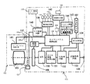
図7は、本実施例におけるカメラシステムの電気的構成を示すブロック図である。ここで、図6で説明した部材と同じ部材については同一符号を用いている。まず、物体像の撮像、記録に関する部分から説明する。 FIG. 7 is a block diagram showing an electrical configuration of the camera system in the present embodiment. Here, the same reference numerals are used for the same members as those described in FIG. First, an explanation will be given from the part related to the imaging and recording of object images.
カメラシステムは、撮像系、画像処理系、記録再生系および制御系を有する。撮像系は、撮影光学系103および撮像素子106を有し、画像処理系は、A/D変換器130、RGB画像処理回路131およびYC処理回路132を有する。また、記録再生系は、記録処理回路133および再生処理回路134を有し、制御系は、カメラシステム制御回路(制御手段)135、操作検出回路(操作検出手段)136、撮像素子駆動回路137およびアイピース駆動回路143を有する。
The camera system has an imaging system, an image processing system, a recording / reproducing system, and a control system. The imaging system has a photographing
138は、外部のコンピュータ等に接続され、データの送受信を行うために規格化された接続端子である。上述した電気回路は、不図示の小型燃料電池からの電力供給を受けて駆動する。
撮像系は、物体からの光を、撮影光学系103を介して撮像素子106の撮像面に結像させる光学処理系である。撮影光学系103内に設けられた不図示の絞りの駆動を制御するとともに、必要に応じてフォーカルプレンシャッタ113の駆動を制御することによって、適切な光量の物体光を撮像素子106で受光させることができる。
The imaging system is an optical processing system that forms an image of light from an object on the imaging surface of the
撮像素子106として、正方画素が長辺方向に3700個、短辺方向に2800個並べられ、合計約1000万個の画素数を有する撮像素子が用いられている。そして、各画素にR(赤色)G(緑色)B(青色)のカラーフィルタが交互に配置され、4画素が一組となるいわゆるベイヤー配列を構成している。
As the
ベイヤー配列では、観察者が画像を見たときに強く感じやすいGの画素をRやBの画素よりも多く配置することで、総合的な画像性能を上げている。一般に、この方式の撮像素子を用いる画像処理では、輝度信号は主にGから生成し、色信号はR、G、Bから生成する。 In the Bayer array, the overall image performance is improved by arranging more G pixels that are easily felt when an observer views the image than the R and B pixels. In general, in image processing using this type of image sensor, a luminance signal is generated mainly from G, and a color signal is generated from R, G, and B.
撮像素子106から読み出された信号は、A/D変換器130を介して画像処理系に供給される。この画像処理系での画像処理によって画像データが生成される。
The signal read from the
A/D変換器130は、撮像素子106の各画素から読み出された信号の振幅に応じて、例えば撮像素子106の出力信号を10ビットのデジタル信号に変換して出力する信号変換回路であり、以降の画像処理はデジタル処理にて実行される。
The A /
画像処理系は、R、G、Bのデジタル信号から所望の形式の画像信号を得る信号処理回路であり、R、G、Bの色信号を輝度信号Yおよび色差信号(R−Y)、(B−Y)にて表わされるYC信号などに変換する。 The image processing system is a signal processing circuit that obtains an image signal in a desired format from R, G, and B digital signals. The R, G, and B color signals are converted into a luminance signal Y and a color difference signal (R−Y), ( B-Y) and the like are converted into a YC signal.
RGB画像処理回路131は、A/D変換器130の出力信号を処理する信号処理回路であり、ホワイトバランス回路、ガンマ補正回路、補間演算による高解像度化を行う補間演算回路を有する。
The RGB
YC処理回路132は、輝度信号Yおよび色差信号R−Y、B−Yを生成する信号処理回路である。このYC処理回路132は、高域輝度信号YHを生成する高域輝度信号発生回路、低域輝度信号YLを生成する低域輝度信号発生回路および、色差信号R−Y、B−Yを生成する色差信号発生回路を有している。輝度信号Yは、高域輝度信号YHと低域輝度信号YLを合成することによって形成される。
The
記録再生系は、不図示のメモリへの画像信号の出力と、ディスプレイユニット107への画像信号の出力とを行う処理系である。記録処理回路133はメモリへの画像信号の書き込み処理および読み出し処理を行い、再生処理回路134はメモリから読み出した画像信号を再生して、ディスプレイユニット107に出力する。
The recording / reproducing system is a processing system that outputs an image signal to a memory (not shown) and outputs an image signal to the
また、記録処理回路133は、静止画データおよび動画データを表わすYC信号を所定の圧縮形式にて圧縮するとともに、圧縮されたデータを伸張させる圧縮伸張回路を内部に有する。圧縮伸張回路は、信号処理のためのフレームメモリなどを有しており、このフレームメモリに画像処理系からのYC信号をフレーム毎に蓄積し、複数のブロックのうち各ブロックから蓄積された信号を読み出して圧縮符号化する。圧縮符号化は、例えば、ブロック毎の画像信号を2次元直交変換、正規化およびハフマン符号化することにより行われる。
The
再生処理回路134は、輝度信号Yおよび色差信号R−Y、B−Yをマトリクス変換して、例えばRGB信号に変換する回路である。再生処理回路134によって変換された信号はディスプレイユニット107に出力され、可視画像として表示(再生)される。再生処理回路134およびディスプレイユニット107は、Bluetoothなどの無線通信を介して接続されていてもよく、このように構成すれば、このカメラで撮像された画像を離れたところからモニタすることができる。
The
一方、制御系における操作検出回路136は、メインスイッチ119、レリーズボタン120、アイピースシャッタ開閉スイッチ123、撮影モード設定スイッチ(モード設定手段)126等(他のスイッチは図7では不図示)の操作を検出して、この検出結果をカメラシステム制御回路135に出力する。
On the other hand, the
ここで、撮影モード設定スイッチ126は、カメラにおいて設定可能な複数の撮影モードのうちいずれか1つの撮影モードを選択して、設定するために操作されるスイッチである。上記撮影モードとしては、例えば、シャッタ優先撮影モード、絞り優先撮影モード、後述するリモート撮影モードおよびセルフタイマ撮影モードがある。
Here, the shooting
カメラシステム制御回路135は、操作検出回路136からの検出信号に応じてカメラシステムでの動作を制御する。また、カメラシステム制御回路135は、撮像動作を行う際のタイミング信号を生成して、撮像素子駆動回路137に出力する。
The camera
撮像素子駆動回路137は、カメラシステム制御回路135からの制御信号を受けることで撮像素子106を駆動させるための駆動信号を生成する。情報表示回路142は、カメラシステム制御回路135からの制御信号を受けて光学ファインダ内情報表示ユニット180の駆動を制御する。アイピースシャッタ駆動回路143は、カメラシステム制御回路135からの制御信号を受けてアイピースシャッタ駆動アクチュエータ(駆動手段)144の駆動を制御する。
The image
制御系は、カメラ本体101に設けられた各種スイッチの操作に応じて撮像系、画像処理系および記録再生系での駆動を制御する。例えば、レリーズボタン120の操作によってSW2がONとなった場合、制御系(カメラシステム制御回路135)は、撮像素子106の駆動、RGB画像処理回路131の動作、記録処理回路133の圧縮処理などを制御する。さらに、制御系は、情報表示回路142を介して光学ファインダ内情報表示ユニット180の駆動を制御することによって、光学ファインダ内での表示(表示セグメントの状態)を変更する。
The control system controls driving in the imaging system, image processing system, and recording / reproducing system in accordance with the operation of various switches provided in the
次に、撮影光学系103の焦点調節動作に関して説明する。
Next, the focus adjustment operation of the photographic
カメラシステム制御回路135はAF制御回路140と接続している。また、レンズ装置102をカメラ本体101に装着することで、カメラシステム制御回路135は、マウント接点101a、102aを介してレンズ装置102内のレンズシステム制御回路141と接続される。そして、AF制御回路140およびレンズシステム制御回路141と、カメラシステム制御回路135とは、特定の処理の際に必要となるデータを相互に通信する。
The camera
焦点検出ユニット121(焦点検出センサ167)は、撮影画面内の所定位置に設けられた焦点検出領域での検出信号をAF制御回路140に出力する。AF制御回路140は、焦点検出ユニット121からの出力信号に基づいて焦点検出信号を生成し、撮影光学系103の焦点調節状態(デフォーカス量)を検出する。そして、AF制御回路140は、検出したデフォーカス量を撮影光学系103の一部の要素であるフォーカシングレンズの駆動量に変換し、フォーカシングレンズの駆動量に関するデータを、カメラシステム制御回路135を介してレンズシステム制御回路141に送信する。
The focus detection unit 121 (focus detection sensor 167) outputs a detection signal in a focus detection area provided at a predetermined position in the shooting screen to the
ここで、移動する物体に対して焦点調節を行う場合、AF制御回路140は、レリーズボタン120が全押し操作されてから実際の撮像制御が開始されるまでのタイムラグを勘案して、フォーカシングレンズの適切な停止位置を予測する。そして、予測した停止位置へのフォーカシングレンズの駆動量に関するデータをレンズシステム制御回路141に送信する。
Here, when focus adjustment is performed on a moving object, the
一方、カメラシステム制御回路135が、撮像素子106の出力信号に基づいて物体の輝度が低く、十分な焦点検出精度が得られないと判定したときには、閃光発光ユニット104又は、カメラ本体101に設けられた不図示の白色LEDや蛍光管を駆動することによって物体を照明する。
On the other hand, when the camera
レンズシステム制御回路141はフォーカシングレンズの駆動量に関するデータを受信すると、レンズ装置102内の不図示の駆動機構を駆動することによってフォーカシングレンズを光軸L1方向に移動させる。なお、上述したようにフォーカシングレンズが液体レンズ等で構成されている場合には、界面形状を変化させることになる。これにより、撮影光学系103の焦点調節動作が行われる。
When the lens
AF制御回路140において物体にピントが合ったことが検出されると、この情報はカメラシステム制御回路135に送信される。このとき、レリーズボタン120の全押し操作によってSW2がON状態になれば、上述したように撮像系、画像処理系および記録再生系によって撮影動作が行われる。
When the
一方、201はアイピースシャッタ開閉検出器(開閉検出手段)、145はハーフミラー111およびサブミラー122を第1から第3の光路分割状態の間で動作させるためのミラー駆動ユニットである。
On the other hand, 201 is an eyepiece shutter open / close detector (open / close detection means), and 145 is a mirror drive unit for operating the
図1から図5は本実施例におけるカメラシステムの断面図である。なお、これらの図においては、レンズ装置102の一部を示している。また、図6で説明した部材と同じ部材については同一符号を用いている。
1 to 5 are sectional views of the camera system in this embodiment. In these drawings, a part of the
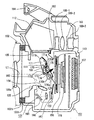
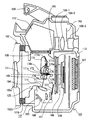
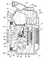
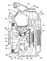
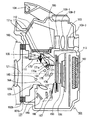
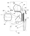
ここで、図1は第2の光路分割状態にあるときのカメラシステムの断面図、図2は第1の光路分割状態および第2の光路分割状態の間で切り替わる途中の状態にあるカメラシステムの断面図である。図3は第1の光路分割状態にあるときのカメラシステムの断面図、図4は第1の光路分割状態および第3の光路分割状態の間で切り替わる途中の状態にあるカメラシステムの断面図、図5は第3の光路分割状態にあるときのカメラシステムの断面図である。 Here, FIG. 1 is a cross-sectional view of the camera system when in the second optical path split state, and FIG. 2 is a diagram of the camera system in the middle of switching between the first optical path split state and the second optical path split state. It is sectional drawing. FIG. 3 is a cross-sectional view of the camera system in the first optical path split state, and FIG. 4 is a cross-sectional view of the camera system in a state where the camera system is in the middle of switching between the first optical path split state and the third optical path split state. FIG. 5 is a cross-sectional view of the camera system in the third optical path division state.
以下、ハーフミラー111およびサブミラー122で構成される光路分割系が上述した第1の光路分割状態にあるときの図(図3)を用いてカメラシステムの構成について説明する。
Hereinafter, the configuration of the camera system will be described with reference to FIG. 3 (FIG. 3) when the optical path splitting system constituted by the
図3において、101はカメラ本体、102はレンズ装置である。レンズ装置102は、レンズ側マウント102bを介してカメラ側マウント101bに装着される。103aは撮影光学系103を構成する複数のレンズのうち最も像面側に位置する撮影レンズ、105はファインダ光学系のフォーカシングスクリーンである。107はディスプレイユニット、163はアイピースシャッタ(ファインダシャッタ)である。
In FIG. 3, 101 is a camera body, and 102 is a lens device. The
164は焦点検出ユニット121における光束の取り込み窓となるコンデンサーレンズ、165はコンデンサーレンズ164からの光束を反射させる反射ミラーである。166は反射ミラー165で反射した光束を焦点検出センサ122上で結像させるための再結像レンズ、122は焦点検出センサである。
111は可動型のハーフミラーで、不図示のハーフミラー受け板に保持されている。ハーフミラー受け板の両側縁部(紙面奥方向および紙面手前方向)には、それぞれピン173が設けられているとともに、一方の側縁部(紙面奥方向)にはピン174が設けられている。ここで、ハーフミラー111とピン173、174は一体的に移動するようになっている。
170はハーフミラー駆動レバー、171はハーフミラー支持アームである。ハーフミラー駆動レバー170は、カメラ本体101に固定された回転軸170aに対して回転可能に支持され、ハーフミラー支持アーム171はカメラ本体101に固定された回転軸171aに対して回転可能に支持されている。
また、ハーフミラー支持アーム171は接続部171bを介してミラーボックスの対向する壁面側に設けられた略同一形状の構造と接続されている。不図示のハーフミラー受け板の両側に設けられたピン173は、ハーフミラー支持アーム171の先端に設けられた貫通孔部171cに係合している。これにより、ハーフミラー111は、ハーフミラー受け板を介して貫通孔部171cを中心に回動可能となっている。
Further, the half
ハーフミラー受け板は、ピン173とピン174の中間位置において不図示のトーションバネによって矢印A方向に付勢されており、該トーションバネの付勢力はハーフミラー受け板を介してハーフミラー111にも働いている。
The half mirror backing plate is biased in the direction of arrow A by a torsion spring (not shown) at an intermediate position between the
第1の光路分割状態では、ミラーストッパ160、161がハーフミラー111の移動領域内に進入した状態にあるため、ハーフミラー111は、上記トーションバネの付勢力を受けてミラーストッパ160、161に当接している。このとき、ピン173とハーフミラー駆動レバー170の第1のカム面170bとの間および、ピン174とハーフミラー駆動レバー170の第2のカム面170cとの間には若干の隙間がある。これにより、ハーフミラー111は、図3に示す状態で位置決めされている。
In the first optical path split state, the
なお、ミラーストッパ160、161は、不図示のミラー駆動機構の駆動によってハーフミラー111の移動領域内に進入したり、退避したりすることができる。また、ミラーストッパ160、161は、ハーフミラー111の移動領域内にあるか移動領域外にあるかを問わず、撮影光路外(撮影光束に影響を与えない位置)に位置している。さらに、後述するミラーストッパ175、176も同様に撮影光路外に位置している。
The
一方、サブミラー122は回転軸125を中心に回転可能となっており、第1の光路分割状態では、図3に示すようにハーフミラー111からの透過光を焦点検出ユニット121(コンデンサーレンズ164)側に反射させる位置に保持されている。
On the other hand, the
第1の光路分割状態において、撮影光学系103からの光束のうち一部の光束はハーフミラー111で反射してファインダ光学系に導かれ、残りの光束はハーフミラー111を透過しサブミラー122で反射して焦点検出ユニット121に導かれる。
In the first optical path division state, a part of the light beam from the photographing
図3に示す状態にあるミラーストッパ160、161がハーフミラー111の移動領域から退避したとき、ハーフミラー111は不図示のトーションバネによる矢印A方向の付勢力を受けて図2に示す状態となる。このとき、トーションバネの付勢力により、ピン173はハーフミラー駆動レバー170の第1のカム面170bに当接し、ピン174はハーフミラー駆動レバー170の第2のカム面170cに当接する。
When the
そして、ハーフミラー駆動レバー170の回転に応じて第1のカム面170bと第2のカム面170cに沿ってピン173、174がそれぞれ摺動し、ハーフミラー111の姿勢が変化する。すなわち、ハーフミラー駆動レバー170の回転に伴ってハーフミラー支持アーム171が回転し、ハーフミラー駆動レバー170およびハーフミラー支持アーム171に対してピン173、174を介して連結されている不図示のハーフミラー受け板とハーフミラー111が一体的に動作する。
And according to rotation of the half
ハーフミラー駆動レバー170およびハーフミラー支持アーム171が図3中反時計方向に回動することによって、ハーフミラー111は図1に示すようにミラーストッパ175、176に当接する。このとき、ハーフミラー111は不図示のトーションバネによる矢印A方向の付勢力を受けているため、図1に示す状態、すなわち第2の光路分割状態に保持される。
As the half
ここで、ハーフミラー111が第1の光路分割状態から第2の光路分割状態に移行するときには、サブミラー122が回転軸125を中心に図3中時計方向に回動することによってミラーボックスの下部まで移動する。すなわち、ハーフミラー111が第1の光路分割状態から第2の光路分割状態に移行する前に、サブミラー122がミラーボックスの下部へ移動することで、ハーフミラー111がサブミラー122に衝突するのを避けている。
Here, when the
第2の光路分割状態では、図1に示すように撮影レンズ103aからの光束のうち一部の光束がハーフミラー111で反射して焦点検出ユニット121に導かれるとともに、残りの光束がハーフミラー111を透過して撮像素子106に到達する。
In the second optical path division state, as shown in FIG. 1, a part of the light flux from the photographing
一方、第1の光路分割状態(図3)から第3の光路分割状態(図5)に移行する際には、ハーフミラー駆動レバー170が図3中時計方向に回転することにより、ハーフミラー111を撮影光路に対してカメラ本体101の上方(フォーカシングスクリーン105側)に退避させる。また、回転軸125を中心としてサブミラー122を図3中時計方向に回転させることにより、サブミラー122を撮影光路に対してカメラ本体101の下側に退避させる。
On the other hand, when shifting from the first optical path split state (FIG. 3) to the third optical path split state (FIG. 5), the
第3の光路分割状態では、図5に示すように撮影レンズ103aからの光束が撮像素子106に到達する。
In the third optical path division state, the light beam from the photographing
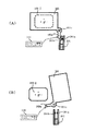
次に、図8を用いて、アイピースシャッタとアイピースシャッタ開閉検出器の構成を説明する。図8は、図1の光射出面側(撮影者の眼球側)から見たときのアイピースシャッタ等の構造を示したものである。図8では、アイピースシャッタ163とアイピースシャッタ開閉検出器201の動きを見やすくするために、カメラ本体101の外装とファインダレンズ109−3は示している。
Next, the configuration of the eyepiece shutter and the eyepiece shutter open / close detector will be described with reference to FIG. FIG. 8 shows the structure of an eyepiece shutter or the like when viewed from the light exit surface side (photographer's eyeball side) of FIG. In FIG. 8, the exterior of the
図8(A)では、アイピースシャッタ163がファインダ光学系の光路内に進入した状態を示し、図8(B)では、アイピースシャッタ163がファインダ光学系の光路から退避した状態を示している。
8A shows a state where the
アイピースシャッタ163は、カメラ本体101に設けられた回転軸101cを中心に回転可能となっており、回転動作によりファインダ光学系の光路内に進入した閉じ位置と上記光路から退避した開き位置との間で移動可能となっている。
The
アイピースシャッタには図8Aと図8Bに、図7に示すアイピース駆動アクチュエータ144があり、カメラシステム制御回路135からの信号に応じてアイピースシャッタの開閉駆動を行う。
The eyepiece shutter includes an
アイピースシャッタ163には突起部163aが形成されている。突起部163aは、不図示の動力伝達機構を介してアイピース駆動アクチュエータ144に連結されており、アイピース駆動アクチュエータ144からの駆動力を受けることで回転軸101cを中心に回転する。これにより、アイピースシャッタ163が回転軸101cを中心に回転する。
The
突起部163aの近傍にはアイピースシャッタ開閉検出器201が配置されている。アイピースシャッタ開閉検出器201は、2つの端子部201a、201bを有している。図8(B)に示すように自由状態では端子部201a、201bが互いに離れて非接触の状態(OFF状態)となっている。また、図8(A)に示すようにアイピースシャッタ開閉検出器201の端部がアイピースシャッタ163によって押し込まれたときには、端子部201a、201bが接触して導通状態(ON状態)となる。
An eyepiece shutter open /
アイピースシャッタ開閉検出器201は、図7に示すようにカメラシステム制御回路135に接続されており、カメラシステム制御回路135はアイピースシャッタ開閉検出器201からのON/OFF信号に基づいてアイピースシャッタ163の動作状態を判別する。
The eyepiece shutter open /
使用者操作によってアイピースシャッタ開閉スイッチ123が閉じ位置に移動すると、操作検出回路136においてアイピースシャッタ開閉スイッチ123の操作状態が検出され、この検出信号がカメラシステム制御回路135に送られる。そして、カメラシステム制御回路135は、アイピース駆動回路143に駆動信号を送り、アイピース駆動アクチュエータ144を駆動させる。これにより、アイピースシャッタ163はアイピース駆動アクチュエータ144からの駆動力を受けることで、ファインダ光学系の光路内に進入する(閉じ状態)。
When the eyepiece shutter opening /
アイピースシャッタ163が閉じ状態になると、図8(A)に示すように突起部163aがアイピースシャッタ開閉検出器201の端部を押し込む。これにより、端子部201bが端子部201aに接触してアイピースシャッタ開閉検出器201が通電状態となり、カメラシステム制御回路135においてアイピースシャッタ163が閉じ状態にあることが検出される。
When the
一方、使用者操作によってアイピースシャッタ開閉スイッチ123が開き位置に移動すると、操作検出回路136においてアイピースシャッタ開閉スイッチ123の操作状態が検出され、この検出信号がカメラシステム制御回路135に送られる。そして、カメラシステム制御回路135は、アイピース駆動回路143に駆動信号を送り、アイピース駆動アクチュエータ144を駆動させる。これにより、アイピースシャッタ163はアイピース駆動アクチュエータ144からの駆動力を受けることで、ファインダ光学系の光路から退避する(開き状態)。
On the other hand, when the eyepiece shutter opening /
アイピースシャッタ163が開き状態になると、図8(B)に示すように突起部163aがアイピースシャッタ開閉検出器201の端部から離れた状態となる。これにより、アイピースシャッタ開閉検出器201は非導通状態となり、カメラシステム制御回路135においてアイピースシャッタ163が開き状態にあることが検出される。
When the
ここで、後述するように第2および第3の光路分割状態では、アイピースシャッタ163が図8(A)に示す閉じ状態となり、第1の光路分割状態では、アイピースシャッタ163が図8(B)に示す開き状態となる。
Here, as described later, in the second and third optical path split states, the
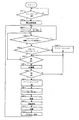
上述した構成のカメラシステムにおける撮影シーケンスについて、図9を用いて説明する。なお、図9に示す動作はカメラシステム制御回路135において行われる。
A shooting sequence in the camera system having the above-described configuration will be described with reference to FIG. The operation shown in FIG. 9 is performed in the camera
ステップS100では、メインスイッチ119がON状態であるか否かを判別する。そして、メインスイッチ119がON状態となったときにはステップS101に進む。ステップS101では、カメラシステム内の電気回路を起動する。ステップS200では、ファインダ切り換えサブルーチンを実行する。ここで、ステップS200における動作の詳細は後述する。
In step S100, it is determined whether or not the
ステップS102では、操作検出回路136を介してアイピースシャッタ開閉スイッチ123の操作が行われたか否かを判別する。アイピースシャッタ開閉スイッチ123の操作が検出されたときには、ステップS200に戻ってファインダ切り換え動作を実行する。一方、アイピースシャッタ開閉スイッチ123の操作が検出されなかったときには、ステップS103に進む。
In step S102, it is determined whether or not the eyepiece shutter opening /
ステップS103では、カメラ本体101に設けられた不図示のリモート撮影・セルフタイマ撮影設定スイッチの操作によってリモート撮影・セルフタイマ撮影モードが設定されているか否かを判別する。
In step S103, it is determined whether or not the remote shooting / self-timer shooting mode is set by operating a remote shooting / self-timer shooting setting switch (not shown) provided in the
リモート撮影とは、カメラ本体101とは別体のリモートコントロール装置の操作によって撮影準備動作および撮影動作を行うものであり、撮影者本人も被写体となって撮影を行いたいときなどに用いられる場合が多い。セルフタイマ撮影とは、レリーズボタン120が全押し操作されてから所定時間経過後に撮影動作が行われるものであり、撮影者本人も被写体となって撮影を行いたいときなどに用いられる場合が多い。
Remote shooting is a shooting preparation operation and shooting operation performed by operating a remote control device separate from the
ステップS103でリモート撮影・セルフタイマ撮影が設定されていると判断したときには、ステップS113に進む。 If it is determined in step S103 that remote shooting / self-timer shooting is set, the process proceeds to step S113.
ステップS113において、カメラシステム制御回路135はアイピース駆動回路143に駆動信号を送り、アイピースシャッタ駆動アクチュエータ144を駆動させることによってアイピースシャッタ163を閉じ状態とさせる。アイピースシャッタ163が閉じ状態になると、アイピースシャッタ開閉検出器201からカメラシステム制御回路135にアイピースシャッタ閉信号が送られ、カメラシステム制御回路135において確実にアイピースシャッタ163が閉じ状態にあることが確認される。
In step S113, the camera
リモート撮影・セルフタイマ撮影では、ファインダ光学系の接眼部を撮影者が覗かないため、カメラ本体101内にファインダ逆入射光(接眼部からファインダ光学系内に入り込む外光)が入りやすい。ファインダ逆入射光が焦点検出ユニット121に到達した場合には検出誤差の要因となり、高精度な焦点検出の阻害要因となる恐れがある。また、ファインダ逆入射光が測光系に到達した場合、すなわち本実施例では撮像素子106の出力に基づいて測光動作を行うため、ファインダ逆入射光が撮像素子106に到達した場合には、測光検出誤差の要因となる恐れがある。
In remote shooting and self-timer shooting, since the photographer does not look into the eyepiece of the finder optical system, finder reverse incident light (external light entering the finder optical system from the eyepiece) is likely to enter the
このため、本実施例では、ステップS113においてアイピースシャッタ163を閉じ状態とすることで、ファインダ逆入射光の発生を防止して高精度な焦点検出と測光を実現している。
For this reason, in this embodiment, the
ステップS103でリモート撮影・セルフタイマ撮影が設定されていないと判断したときには、ステップS104に進む。 When it is determined in step S103 that remote shooting / self-timer shooting is not set, the process proceeds to step S104.
ステップS104では、レリーズボタン120の半押し操作によってSW1がON状態になっているか否かを判別する。ここで、SW1がOFF状態の場合にはステップS102に戻り、アイピースシャッタ開閉スイッチ123の操作が行われたか否かを判別する。一方、SW1がON状態である場合には、ステップS105に進む。
In step S104, it is determined whether or not SW1 is in an ON state by a half-press operation of the
ステップS105では、カメラシステム制御回路135からAF制御回路140にAF開始信号を送る。これにより、AF制御回路140は、焦点検出ユニット121での検出動作を開始させるとともに、焦点検出ユニット121の出力(焦点検出結果)に基づいて焦点調節動作を開始する。
In step S105, an AF start signal is sent from the camera
ステップS106では、レリーズボタン120の全押し操作によってSW2がON状態にあるか否かを判別する。ここで、SW2がOFF状態である場合には再びステップS104に進み、SW1がON状態であるか否かを判別する。一方、SW2がON状態である場合には、ステップS107に進む。
In step S106, it is determined whether or not SW2 is in an ON state by a full pressing operation of the
ステップS107では、カメラシステム制御回路135からアイピース駆動回路143に駆動信号を送り、アイピースシャッタ駆動アクチュエータ144を駆動することでアイピースシャッタ163を閉じ状態にさせる。なお、ステップS113でアイピースシャッタ163を閉じ状態としている場合には、ステップS107での動作は行わない。
In step S107, a drive signal is sent from the camera
アイピースシャッタ163が閉じ状態になると、アイピースシャッタ開閉検出器201からカメラシステム制御回路135にアイピースシャッタ閉信号が送られ、カメラシステム制御回路135において確実にアイピースシャッタ163が閉じたことが確認される。
When the
ステップS108では、カメラシステム制御回路135からミラー駆動ユニット145にミラー駆動開始信号を送り、ハーフミラー111およびサブミラー122を図5に示す位置に移動させて第3の光路分割状態とする。第3の光路分割状態では、図5に示すようにハーフミラー111およびサブミラー122が撮影光路から退避するため、撮影レンズ103aからの光束がダイレクトに撮像素子106に到達する。
In step S108, a mirror drive start signal is sent from the camera
ステップS109において、カメラシステム制御回路135は、レンズシステム制御回路141を介してレンズ装置102内に設けられた不図示の絞りの駆動を制御する。具体的には、測光結果に基づいて決定された絞り値となるように絞りの駆動を制御する。また、必要に応じてフォーカルプレンシャッタ113の駆動を制御する。具体的には、測光結果に基づいて決定されたシャッタ速度となるようにフォーカルプレンシャッタ113の駆動を制御する。これにより、適切な光量の物体光が、撮影光学系103を通過して撮像素子106の撮像面で結像する。
In step S <b> 109, the camera
そして、カメラシステム制御回路135は、撮像素子駆動回路137に撮像開始信号を送ることにより、撮像素子106を駆動させる。これにより、撮像素子106において受光量に応じた電気信号が蓄積されるとともに、蓄積された信号が読み出される(撮像動作)。
Then, the camera
ステップS110では、撮像素子106から読み出された信号が、A/D変換器130を介してRGB画像処理回路131に送られ、ホワイトバランス処理、ガンマ補正、補間演算処理が施される。さらに、YC処理回路132でYC処理がなされて画像処理が完了する。この画像処理によって高精彩な画像を得ることができる。
In step S110, the signal read from the
ステップS111では、画像データを記録処理回路133に送り、所定の圧縮形式で圧縮した後、記録媒体に記録する。
In step S111, the image data is sent to the
ステップS112では、画像データを再生処理回路134に送り、ディスプレイユニット107において撮影画像のプレビュー表示を行う。プレビュー表示後は、ファインダ切り換えサブルーチン(ステップS200)に戻り、アイピースシャッタ開閉スイッチ123の操作状態に応じて光路分割状態を変更する。
In step S112, the image data is sent to the
上述したフローでは、カメラシステムがリモート撮影・セルフタイマ撮影モードに設定されている場合および、カメラ本体101(光路分割系)が第3の光路分割状態にある場合において、アイピースシャッタ163を閉じ状態とすることによってファインダ逆入射光がカメラ本体101内に入り込まないようにしている。
In the flow described above, the
ここで、第3の光路分割状態では、光を透過させるハーフミラー111がフォーカシングスクリーン105の下側に配置されている。このため、ファインダ逆入射光がファインダ光学系およびハーフミラー111を透過して撮像素子106の受光面に到達するおそれがある。そこで、本実施例では、カメラ本体101が第3の光路分割状態にある場合にアイピースシャッタ163を閉じ状態とすることによってファインダ逆入射光が撮像素子106の受光面に到達しないようにしている。
Here, in the third optical path division state, the
しかも、本実施例では、リモート撮影・セルフタイマ撮影モードの設定状態や光路分割状態に応じて自動的にアイピースシャッタ163が閉じ状態となるため、手動でアイピースシャッタを閉じ状態とさせる場合に比べてカメラの使い勝手を向上させることができる。
In addition, in this embodiment, the
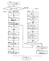
次に、ファインダ切り換えサブルーチン(ステップS200)について、図10を用いて説明する。 Next, the finder switching subroutine (step S200) will be described with reference to FIG.
ステップS201において、カメラシステム制御回路135は操作検出回路136を介してアイピースシャッタ開閉スイッチ123の操作状態(閉じ位置又は開き位置)を判別する。アイピースシャッタ開閉スイッチ123が閉じ位置にある場合には、ステップS202に進む。アイピースシャッタ開閉スイッチ123が閉じ位置にある場合、カメラシステム制御回路135はカメラ本体101をEVFモード(図1に示す状態)に設定するためにステップS202〜ステップS210の動作を行う。
In step S <b> 201, the camera
ここで、ステップS202〜ステップS210までの動作は、OVFモード(図3に示す状態)からEVFモードに切り換える動作である。 Here, the operations from step S202 to step S210 are operations for switching from the OVF mode (the state shown in FIG. 3) to the EVF mode.
撮影者がアイピースシャッタ開閉スイッチ123を閉じ位置に移動させることは、撮影者がファインダ光学系を使う意思がなく、ディスプレイユニット107での表示画像を見ながら撮影することを望んでいることになる。このため、アイピースシャッタ開閉スイッチ123が閉じ位置にある場合にEVFモードに移行することは、撮影者の意図に適切に応じることになる。
When the photographer moves the eyepiece shutter opening /
ステップS202において、カメラシステム制御回路135はアイピース駆動回路143に駆動信号を送り、アイピース駆動アクチュエータ144を駆動することにより、アイピースシャッタ163を閉じ状態とさせる。アイピースシャッタ163が閉じ状態になると、アイピースシャッタ開閉検出器201からカメラシステム制御回路135にアイピースシャッタ閉信号が送られ、カメラシステム制御回路135において確実にアイピースシャッタ163が閉じ状態にあることが確認される。
In step S202, the camera
ステップS203では、光学ファインダ内情報表示ユニット180の駆動を停止させることで、ファインダ視野内での表示状態を非表示状態(消灯)とする。ステップS203では、すでにアイピースシャッタ163が閉じ状態となっているため、ファインダ視野内での表示を消すことにより、カメラ本体101における電力消費を抑えて、電池の消耗を抑制することができる。
In step S203, the display of the
ステップS204では、ハーフミラー111を第1の光路分割状態から第2の光路分割状態に移動させるのに備えて、撮影光路上に配置されたサブミラー122を回転させてミラーボックス下部に移動させる。
In step S204, in preparation for moving the
ステップS205では、ミラーストッパ160、161をハーフミラー111の移動領域から退避させる。ミラーストッパ160、161が退避した後、ステップS206でハーフミラー駆動レバー170を図3中反時計方向に回転させると、ミラー駆動機構内の不図示のバネの付勢力によりハーフミラー111は図2に示す状態を経て第2の光路分割状態(図1)にまで駆動される。ハーフミラー111が第2の光路分割状態となることで、撮影レンズ103aからの光束がハーフミラー111で反射して、焦点検出ユニット121に導かれることになる。
In step S205, the
第2の光路分割状態では、ピン173とハーフミラー駆動レバー170の第1のカム面170bの間および、ピン174とハーフミラー駆動レバー170の第2のカム面170cの間には若干の隙間が生じ、ハーフミラー111はミラーストッパ175、176に当接して位置決めされる。ここで、第2の光路分割状態にあるハーフミラー111の反射面の位置が、第1の光路分割状態にあるサブミラー122の反射面の位置と同じとなるように、ミラーストッパ175、176が配置されている。
In the second optical path split state, there is a slight gap between the
このように構成することによって、OVFモードとEVFモードで焦点検出ユニット121に入射する光束の位置がずれてしまうのを防止でき、焦点検出ユニット121での検出動作を正確に行わせることができる。
With this configuration, it is possible to prevent the position of the light beam incident on the
撮影レンズ103aからの光束がハーフミラー111を透過する場合、上記光束はハーフミラー111において屈折作用を受けるため、ハーフミラー111を透過した光束が撮像素子106上で形成する物体像のピント位置は、ハーフミラー111を透過しない場合に比べて若干ずれる。このため、ステップS207では、上記ずれを補正するためのピント補正モードを起動する。
When the light beam from the
第1の光路分割状態にあるときに焦点検出ユニット121から出力される焦点検出信号は、第3の光路分割状態において撮影レンズ103aからの光束が撮像素子106上で結像したときの結像状態を示すようになっている。これに対して、第2の光路分割状態においてピント補正モードが設定されているときには、撮影レンズ103aからの光束がハーフミラー111を透過して撮像素子106上で結像したときの結像状態を示すように、上記焦点検出信号を補正している。このため、第2の光路分割状態におけるフォーカスレンズの合焦位置は、第1および第3の光路分割状態での合焦位置に対して焦点検出信号を補正した分だけずれることになる。
The focus detection signal output from the
したがって、EVFモードにおいてSW2をオンにして撮影動作を行う場合、すなわち、光路分割系を第2の光路分割状態から第3の光路分割状態に切り換える場合には、フォーカルプレンシャッタ113の先幕駆動機構のチャージとともに、フォーカスレンズの位置を上述したズレの分だけ補正する。この後、フォーカルプレンシャッタ113を所定時間だけ開き状態とすることで、撮像素子106による撮像動作を行う。
Therefore, in the EVF mode, when the photographing operation is performed with SW2 turned on, that is, when the optical path division system is switched from the second optical path division state to the third optical path division state, the front curtain drive mechanism of the
上述したように構成することで、EVFモード(第2の光路分割状態)においてはディスプレイユニット107でピントのあった画像を確認することができ、第3の光路分割状態で撮影を行ったときにもピントのあった撮影画像を得ることができる。
By configuring as described above, in the EVF mode (second optical path division state), a focused image can be confirmed on the
ステップS208では、フォーカルプレンシャッタ113の先幕だけを走行させてバルブ露光状態にすることで、撮影光学系103を通過した物体光を連続的に撮像素子106に到達させ、ディスプレイユニット107上で画像を表示させるための撮像が可能な状態とする。
In step S208, only the front curtain of the
ステップS209では、ディスプレイユニット107の電源を投入する。ステップS210では、撮影光学系103によって形成された物体像に対して撮像素子106による撮像動作を連続的に行い、撮像素子106から読み出されて画像処理された画像データをディスプレイユニット107上でリアルタイム表示させる。そして、OVFモードからEVFモードへの切り替え動作を終了する。
In step S209, the
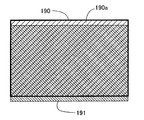
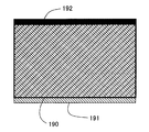
ここで、EVFモードである第2の光路分割状態では、撮影レンズ103aからの光束がハーフミラー111で屈折してから撮像素子106に到達する。このため、図13に示すように、第2の光路分割状態における撮像素子106の受光領域190が、第3の光路分割状態における撮像素子106の受光領域191に対して撮像素子106の上下方向(図1の上下方向)で僅かにずれてしまうことがある。すなわち、第2の光路分割状態においてディスプレイユニット107でリアルタイム表示される画像が、第3の光路分割状態で撮影された画像と一致せずにずれてしまうことがある。
Here, in the second optical path division state that is the EVF mode, the light beam from the photographing
ここで、領域190のうち領域191と重ならない領域190aは、ディスプレイユニット107上でリアルタイム表示されるものの、第3の光路分割状態での撮影によって得られた画像には含まれない領域となる。
Here, an
本実施例のカメラでは、図14に示すように、ディスプレイユニット107上でリアルタイム表示される画像領域のうち領域190aに相当する領域192をブラックアウトさせて、領域190全体を表示させないようにしている。この処理は、再生処理回路134において行われる。
In the camera of the present embodiment, as shown in FIG. 14, the
これにより、実際に撮影された画像の中に、ディスプレイユニット107でリアルタイム表示された画像が含まれていないといった不具合を避けることができる。
As a result, it is possible to avoid a problem such that an image actually displayed on the
次に、図10のステップS201において、アイピースシャッタ開閉スイッチ123が開き位置にあると判断したときの動作について説明する。すなわち、カメラをEVFモードからOVFモードに切り換える際の動作について説明する。
Next, the operation when it is determined in step S201 in FIG. 10 that the eyepiece shutter opening /
アイピースシャッタ開閉スイッチ123は開き位置にある場合には、カメラシステム制御回路135はOVFモードが選択されていると判別し、カメラをOVFモードに応じた状態とするために以下に説明する動作を行う。
When the eyepiece shutter opening /
ここで、アイピースシャッタ163を開けるということは、撮影者が光学ファインダを使うことを望んでいることを意味する。このため、アイピースシャッタ開閉スイッチ123が開き位置にあることを検知してOVFモードに移行することは、撮影者の意図に適切に応じることができる。
Here, opening the
ステップS220では、ディスプレイユニット107の電源をオフにするとともに、撮像素子106による撮像動作を停止させる。
In step S220, the
ステップS221では、フォーカルプレンシャッタ113の後幕を走行させてシャッタを閉じ状態とし、撮影に備えて先幕および後幕の駆動機構をチャージする。ステップS222では、後のステップで行われるハーフミラー111の移動を可能にするために、ミラーストッパ160、161をハーフミラー111の移動領域から退避させる。
In step S221, the rear curtain of the
ステップS223では、ハーフミラー駆動レバー170を図1中時計回りに回転させて、ハーフミラー111だけを図2の状態→図3の状態→図4の状態→図5の状態の順に移動させる。このとき、ハーフミラー111は、第1の光路分割状態(図3)を経て、第3の光路分割状態(図5)となる。
In step S223, the half
ステップS224では、ミラーストッパ160、161をハーフミラー111の移動領域内に進入させ、ハーフミラー111を位置決めするための所定位置まで移動させる。
In step S224, the
上述したように、ミラーストッパ160、161をハーフミラー111の移動領域から退避させてからハーフミラー111を第3の光路分割状態まで移動させ、その後ミラーストッパ160、161をハーフミラー111の移動領域内に進入させているため、ハーフミラー111が移動する際にミラーストッパ160、161と衝突することはない。これにより、OVFモードからEVFモードに切り換える際の機構的信頼性を高くできる。
As described above, after the
ステップS225では、ハーフミラー駆動レバー170を図5中反時計回りに回転させて、ハーフミラー111を第3の光路分割状態(図5の状態)から図4の状態を経て、第1の光路分割状態(図3の状態)に移動させる。ここで、ハーフミラー111は、ミラー駆動機構内の不図示のバネの付勢力(図3の矢印Aに示す力)を受けることにより、ミラーストッパ160、161に当接した状態となる。
In step S225, the half
ステップS226において、カメラシステム制御回路135は、アイピース駆動回路143およびアイピース駆動アクチュエータ144を介してアイピースシャッタ163を開き状態とさせる。アイピースシャッタ163が開き状態になると、図8に示すアイピースシャッタ開閉検出器201からカメラシステム制御回路135にアイピースシャッタ開信号が送られ、カメラシステム制御回路135においてアイピースシャッタ163が確実に開いたことが確認される。
In step S226, the camera
ステップS227において、カメラシステム制御回路135は、カメラシステム内に設けられたAF/MF切換スイッチ(不図示)の操作状態に基づいて、マニュアルフォーカスモードに設定されているか否かを判別する。ここで、マニュアルフォーカスモードに設定されていればステップS205に移行し、マニュアルフォーカスモードに設定されておらず、オートフォーカスモードに設定されていればステップS228に進む。
In step S227, the camera
マニュアルフォーカスモードに設定されている場合には、焦点検出ユニット121を動作させる必要がなく、また、OVFを用いるよりもEVFを用いる方が背景(被写体像)のボケ具合を正確に把握することができる。このため、マニュアルフォーカスモードに設定されているときには、ディスプレイユニット107でのリアルタイム表示を行うために、ステップS205に進む。
When the manual focus mode is set, it is not necessary to operate the
ここで、ステップS205に進む場合、アイピースシャッタ163を閉じ状態にさせる。これにより、EVFを用いた被写体観察を優先させることができるとともに、ファインダ光学系からの逆入射光がリアルタイム表示される画像に悪影響を与えるのを抑制することができる。
Here, when the process proceeds to step S205, the
ステップS228では、サブミラー122を撮影光路内に進入させて、ハーフミラー111を透過した物体光を焦点検出ユニット121に導く所定の位置にセットする。ここで、ステップS220からステップS227までの処理を行う間、サブミラー122は第2の光路分割状態(図1)での位置、すなわち撮影光路から退避した位置にあり、ステップS228に進んだときに動作することになる。
In step S 228, the
ステップS229において、カメラシステム制御回路135は光学ファインダ内情報表示ユニット180を駆動させて、ファインダ内情報表示を点灯させる。そして、EVFモードからOVFモードへの切り換え動作を終了する。
In step S229, the camera
本実施例では、撮像画像をディスプレイユニット107で表示させる場合、すなわちEVFモードの場合には、ハーフミラー111およびサブミラー122を有する光路分割系が第2の光路分割状態(図1)となっており、撮影レンズ103aからの光束を焦点検出ユニット121に導いている。これにより、EVFモードのときにも、焦点検出ユニット121での位相差検出方式による焦点検出に基づいて、高速な焦点調節動作を行わせることができる。
In this embodiment, when the captured image is displayed on the
ファインダ切り換えサブルーチン(ステップS200)において、OVFモードおよびEVFモード間の切り換えは、アイピースシャッタ開閉スイッチ123の状態に基づいて判別している。
In the finder switching subroutine (step S200), switching between the OVF mode and the EVF mode is determined based on the state of the eyepiece shutter opening /
撮影者がファインダ光学系を使用して撮影を行おうとする場合、必ずアイピースシャッタ開閉スイッチ123を開き位置に移動させて、アイピースシャッタ163を開き状態にする。つまり、アイピースシャッタ開閉スイッチ123が開き位置にあることは、ファインダ光学系を使用しようとする撮影者の意図を反映したものであり、これに伴ってOVFモードに設定することは理にかなっている。
When the photographer intends to take a picture using the finder optical system, the eyepiece shutter opening /
一方、撮影者がアイピースシャッタ開閉スイッチ123を閉じ位置に移動させた場合には、ファインダ光学系を使用する意思がないことを意味する。つまり、アイピースシャッタ開閉スイッチ123が閉じ位置にあることは、電子画像表示を使用しようとする撮影者の意図を反映したものであり、これに伴ってEVFモードに設定することは理にかなっている。
On the other hand, when the photographer moves the eyepiece shutter opening /
以上のように、アイピースシャッタ開閉スイッチ123の状態(閉じ位置又は開き位置)に応じて、OVFモードおよびEVFモード間の切り換えを行うことで、撮影者の意図に適切に応じることができる。
As described above, by switching between the OVF mode and the EVF mode according to the state (closed position or open position) of the eyepiece shutter opening /
次に、焦点検出ユニット121における焦点検出のための信号処理について説明する。
Next, signal processing for focus detection in the
撮影レンズ103aから射出した光束(物体光)は、第2の光路分割状態ではハーフミラー111で反射し、第1の光路分割状態ではサブミラー122で反射した後、ミラーボックスの下部に設けられたコンデンサーレンズ164に入射する。そして、コンデンサーレンズ164に入射した光束は、反射ミラー165で偏向し、再結像レンズ166の作用によって焦点検出センサ167上に物体の2次像を形成する。
The light beam (object light) emitted from the
焦点検出センサ167には少なくとも2つの画素列が備えられている。2つの画素列それぞれから出力される信号波形を比較すると、撮影光学系103によって形成された物体像の焦点検出領域上での結像状態に応じて、相対的に横シフトした状態が観測される。上記結像状態が前ピンか後ピンかで、出力信号波形のシフト方向が逆になり、相関演算などの手法を用いてシフト方向およびシフト量(位相差)を検出するのが焦点検出の原理である。
The
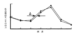
図11と図12は、AF制御回路140に入力された焦点検出センサ167の出力信号波形を表す図である。横軸は画素の並びを示し、縦軸は焦点検出センサ167の出力値を示している。図11では、物体像にピントが合っていない状態での出力信号波形を示し、図12では、物体像にピントが合った状態での出力信号波形を示している。
11 and 12 are diagrams showing output signal waveforms of the
一般に、焦点検出に用いられる光束は絞り開放状態での結像光束と同じではなく、結像光束の一部となっている。すなわち、焦点検出を行う場合には、暗いFナンバーの光束が用いられる。また、カメラ内の機構の誤差を考慮すると、撮像素子106の位置と焦点検出センサ167の位置が厳密な意味で光学的に共役とはいえない。
In general, the light beam used for focus detection is not the same as the imaging light beam in the fully open state, but is a part of the imaging light beam. That is, when performing focus detection, a dark F-number light beam is used. Further, in consideration of the error of the mechanism in the camera, the position of the
このため、物体像にピントが合った状態であっても、図12に示すように2つの出力信号波形の間には、僅かの初期位相差Δが残る。該初期位相差Δは、上述したピント補正モード(図10のステップS207参照)において焦点検出信号に対する補正で用いられるものとは異なるものである。 Therefore, even when the object image is in focus, a slight initial phase difference Δ remains between the two output signal waveforms as shown in FIG. The initial phase difference Δ is different from that used in the correction for the focus detection signal in the above-described focus correction mode (see step S207 in FIG. 10).
ここで、2つの像の相関演算で検出された位相差から初期位相差Δを差し引けば真の位相差を知ることができるため、初期位相差Δの存在自体は通常問題とならない。 Here, since the true phase difference can be obtained by subtracting the initial phase difference Δ from the phase difference detected by the correlation calculation of the two images, the presence of the initial phase difference Δ is not usually a problem.
本実施例では、上述したように焦点検出に用いられる光束が、第1の光路分割状態においてサブミラー122から導かれる場合と、第2の光路分割状態においてハーフミラー111から導かれる場合とがある。この場合、第1の光路分割状態(図3)でのサブミラー122の反射面位置と、第2の光路分割状態(図1)でのハーフミラー111の反射面位置が、機構精度上完全には一致せず、光路分割状態に応じて初期位相差Δの値が異なってしまう。このため、相関演算で検出された位相差から一定の初期位相差Δを差し引いただけでは、第1および第2の光路分割状態での真の位相差を知ることができない。
In the present embodiment, as described above, the light beam used for focus detection may be guided from the
通常の部品加工精度では、2つの反射面位置が、該反射面の垂直方向に略30μm程度ずれる可能性がある。ここで、反射面位置のずれをメカ的に小さくしようとすると、部品加工のためのコストが極めて高くなってしまう。 With normal component processing accuracy, there is a possibility that the positions of the two reflecting surfaces are shifted by approximately 30 μm in the direction perpendicular to the reflecting surfaces. Here, if it is attempted to mechanically reduce the displacement of the reflecting surface position, the cost for processing the parts becomes extremely high.
そこで、本実施例では、第1の光路分割状態と第2の光路分割状態で初期位相差Δをそれぞれ設定し、光路分割状態に応じた初期位相差Δを用いることにより、焦点検出センサ167の出力信号に対して補正を行うようにしている。これにより、光路分割状態に応じた真の位相差を知ることができ、該位相差に基づいて精度の良い焦点検出を行うことができる。
Therefore, in the present embodiment, the initial phase difference Δ is set for each of the first optical path split state and the second optical path split state, and the initial phase difference Δ corresponding to the optical path split state is used, whereby the
このように、初期位相差を考慮に入れて一組の信号の同一性を判定することで撮影光学系が合焦状態にあるか否かを判別できる。また、相関演算を用いた公知の手法、例えば特公平5−88445号公報に開示されている手法を用いて位相差を検出することにより、デフォーカス量を求めることができる。そして、得られたデフォーカス量を撮影光学系103のフォーカシングレンズの駆動量に換算し、該駆動量の分だけフォーカシングレンズを駆動させれば撮影光学系の焦点調節を自動で行うことができる。
As described above, it is possible to determine whether or not the photographing optical system is in a focused state by determining the identity of a set of signals in consideration of the initial phase difference. Further, the defocus amount can be obtained by detecting a phase difference using a known method using correlation calculation, for example, a method disclosed in Japanese Patent Publication No. 5-88445. Then, if the obtained defocus amount is converted into the driving amount of the focusing lens of the photographing
位相差検出方式では、フォーカシングレンズの駆動量があらかじめ分かるので、通常、合焦位置までのレンズ駆動はほぼ一回で済み、極めて高速な焦点調節が可能である。 In the phase difference detection method, since the driving amount of the focusing lens can be known in advance, the lens driving to the in-focus position is usually performed only once, and extremely fast focus adjustment is possible.
本実施例によれば、ファインダ光学系を用いて物体像を観察する場合(OVFモードの場合)に加えて、ディスプレイユニット107で物体像をリアルタイム表示させる場合(EVFモードの場合)にも、焦点検出ユニット121において位相差検出方式による焦点検出を行うことができ、撮影光学系の焦点調節動作を高速で行うことができる。また、第2の光路分割状態(図1)で連続撮影や動画撮影を行うようにすれば、これらの撮影においても高速な焦点調節が可能となる。さらに、従来のように2つの焦点検出ユニットを設ける必要はないため、コストアップとなることもない。
According to the present embodiment, in addition to the case of observing an object image using a finder optical system (in the case of OVF mode), the focus is applied to the case where the object image is displayed on the
本実施例において、第2の光路分割状態(図1)では、撮影レンズ103aからの光束を焦点検出ユニット121に導き、焦点検出ユニット121において位相差検出方式による焦点検出を行わせているが、該光路分割状態では撮像素子106にも撮影レンズ103aからの光束が到達するため、撮像素子106の出力に基づいてコントラスト検出方式による焦点調節を合わせて行うようにしてもよい。すなわち、位相差検出方式による焦点検出結果に基づいてフォーカスレンズを駆動させた後に、コントラスト検出方式による焦点調節を行うことで、フォーカスレンズを合焦位置まで精度良く移動させることができる。
In this embodiment, in the second optical path division state (FIG. 1), the light beam from the photographing
ここで、コントラスト検出方式による焦点調節とは、撮像光学系103によって形成された物体像の鮮鋭度を、撮像素子106の出力に対して所定の関数で評価することによって求め、関数値が極値をとるようにフォーカスレンズの光軸上の位置を調節するものである。
Here, the focus adjustment by the contrast detection method is obtained by evaluating the sharpness of the object image formed by the imaging
評価関数としては、隣接する輝度信号の差の絶対値を焦点検出領域内で加算するものや、隣接する輝度信号の差の2乗を焦点検出領域内で加算するもの、あるいはR、G、Bの各画像信号のうち隣接する信号の差に対して上記と同様に処理するもの等がある。 As an evaluation function, an absolute value of a difference between adjacent luminance signals is added within the focus detection area, a square of the difference between adjacent luminance signals is added within the focus detection area, or R, G, B Among these image signals, there is one that processes the difference between adjacent signals in the same manner as described above.
一方、本実施例では、アイピースシャッタ開閉スイッチ123の操作位置(開き位置および閉じ位置)に応じて、EVFモード(第2の光路分割状態)およびOVFモード(第1の光路分割状態)間の切り換えを自動的に行うようになっているため、使用者にとって使い勝手の良いカメラシステムとなる。しかも、EVFモードではアイピースシャッタを閉じ状態としているため、ファインダ光学系からの逆入射光が焦点検出ユニット121内に取り込まれるのを確実に防ぐことができ、焦点検出ユニット121での位相差検出方式による焦点検出の精度を高めることができる。また、第3の光路分割状態で撮影を行う際にアイピースシャッタ163を閉じ状態にしてファインダ光学系からの逆入射光を防いでいるため、該逆入射光によって撮影画像に悪影響を与えるのを防止して、高品位な撮影画像を得ることができる。
On the other hand, in this embodiment, switching between the EVF mode (second optical path split state) and the OVF mode (first optical path split state) is performed according to the operation position (open position and close position) of the eyepiece shutter opening /
また、リモート撮影及びセルフタイマ撮影を行うときに、アイピースシャッタ163を閉じ状態にしてファインダ光学系からの逆入射光を防いでいるため、位相差検出方式による焦点検出の精度を高めることができるととにも、高品位な撮影画像を得ることができる。
Also, when performing remote shooting and self-timer shooting, the
本実施例では、カメラシステム制御回路135が、アイピース駆動回路143を介してアイピース駆動アクチュエータ144の駆動を制御することによって、アイピースシャッタ163を開閉動作させているが、撮影者の操作(手動)によってアイピースシャッタ163を開閉動作させるようにしてもよい。例えば、アイピースシャッタ163に連結されるレバー部材を設け、撮影者がレバー部材を操作することによってアイピースシャッタ163を開閉させることができる。この場合、カメラシステム制御回路135は、アイピースシャッタ開閉検出器201からの出力信号に基づいてアイピースシャッタ163の開閉状態を検出し、該検出結果に応じてOVFモードおよびEVFモード間の切り換え動作(図10に示す動作)を行うようにすることができる。
In this embodiment, the camera
103・・・撮影光学系
105・・・フォーカシングスクリーン
106・・・撮像素子
107・・・ディスプレイユニット
109・・・ファインダレンズ
111・・・ハーフミラー
121・・・焦点検出ユニット
122・・・サブミラー
123・・・アイピースシャッタ開閉スイッチ
135・・・カメラシステム制御回路
163・・・アイピースシャッタ
103: Imaging
Claims (7)
前記光束により光学的に被写体像の観察を可能とするファインダ光学系と、
前記光束を前記ファインダ光学系に向けて反射する第1の状態と前記光束を前記撮像素子に到達させる第2の状態とに切り換え駆動されるミラーユニットと、
前記ファインダ光学系の光路を開閉するファインダシャッタと、
前記ファインダシャッタの開閉動作を行わせるために操作される操作手段と、
前記ミラーユニットの駆動を制御する制御手段とを有し、
前記制御手段は、前記操作手段が開側に操作されることに応じて前記ミラーユニットを前記第1の状態に駆動し、前記操作手段が閉側に操作されることに応じて前記ミラーユニットを前記第2の状態に駆動することを特徴とする撮像装置。 An image sensor that photoelectrically converts a subject image formed by a light beam from a photographing lens;
A finder optical system that enables optical observation of a subject image by the luminous flux;
A mirror unit that is driven to switch between a first state in which the light beam is reflected toward the finder optical system and a second state in which the light beam reaches the imaging element;
A finder shutter for opening and closing the optical path of the finder optical system;
Operating means operated to open and close the viewfinder shutter;
Control means for controlling the drive of the mirror unit,
The control means drives the mirror unit to the first state in response to the operation means being operated to the open side, and controls the mirror unit in response to the operation means being operated to the close side. An imaging apparatus that is driven to the second state.
前記制御手段は、前記操作検出手段からの信号に基づいて前記ミラーユニットを駆動することを特徴とする請求項1に記載の撮像装置。 An operation detecting means for detecting an operation of the operating means;
The imaging apparatus according to claim 1, wherein the control unit drives the mirror unit based on a signal from the operation detection unit.
前記制御手段は、前記開閉検出手段からの信号に基づいて前記ミラーユニットを駆動することを特徴とする請求項1に記載の撮像装置。 Open / close detecting means for detecting opening / closing of the finder shutter;
The imaging apparatus according to claim 1, wherein the control unit drives the mirror unit based on a signal from the open / close detection unit.
前記第1の状態は、前記光束を前記ファインダ光学系および前記焦点検出手段に向けて反射する状態であることを特徴とする請求項1から3のいずれか1つに記載の撮像装置。 A focus detection unit that detects a focus state of the photographing lens using the light beam;
4. The imaging apparatus according to claim 1, wherein the first state is a state in which the light beam is reflected toward the finder optical system and the focus detection unit. 5.
前記第1の状態は、前記光束を前記ファインダ光学系および前記焦点検出手段に向けて反射する状態であり、前記第2の状態は、前記光束を前記撮像素子に向けて透過させるとともに前記焦点検出手段に向けて反射する透過/反射状態もしくは前記撮影レンズから前記撮像素子への撮影光路から前記ミラーユニットが退避した退避状態であることを特徴とする請求項1から3のいずれか1つに記載の撮像装置。 A focus detection unit that detects a focus state of the photographing lens using the light beam;
The first state is a state in which the light beam is reflected toward the finder optical system and the focus detection means, and the second state is a state in which the light beam is transmitted toward the image sensor and the focus detection is performed. The transmission / reflection state of reflecting toward the means, or the retracted state in which the mirror unit is retracted from the imaging optical path from the imaging lens to the imaging device. Imaging device.
前記第1の状態では前記第1および第2のミラー部材が前記撮影光路内に配置され、前記透過/反射状態では前記第1のミラー部材が前記撮影光路内に配置されるとともに前記第2のミラー部材が前記撮影光路から退避し、前記退避状態では前記第1および第2のミラー部材が前記撮影光路から退避することを特徴とする請求項5に記載の撮像装置。 The mirror unit includes a first mirror member that reflects a part of the light beam and transmits the remainder, and a second mirror member that reflects the light beam transmitted through the first mirror member,
In the first state, the first and second mirror members are disposed in the photographing optical path. In the transmission / reflection state, the first mirror member is disposed in the photographing optical path and the second mirror member is disposed in the photographing optical path. 6. The imaging apparatus according to claim 5, wherein a mirror member is retracted from the photographing optical path, and the first and second mirror members are retracted from the photographing optical path in the retracted state.
The imaging apparatus includes mode setting means capable of setting a plurality of shooting modes including a remote shooting mode and a self-timer shooting mode, and the control means includes at least one of the remote shooting mode and the self-timer shooting mode. The imaging apparatus according to claim 1, wherein the finder shutter is closed regardless of the operation of the operation unit when one of the settings is set.
Priority Applications (2)
| Application Number | Priority Date | Filing Date | Title |
|---|---|---|---|
| JP2004108512A JP4678816B2 (en) | 2004-03-31 | 2004-03-31 | Imaging device |
| US11/093,779 US7483072B2 (en) | 2004-03-31 | 2005-03-30 | Image-taking apparatus and image-taking system |
Applications Claiming Priority (1)
| Application Number | Priority Date | Filing Date | Title |
|---|---|---|---|
| JP2004108512A JP4678816B2 (en) | 2004-03-31 | 2004-03-31 | Imaging device |
Publications (3)
| Publication Number | Publication Date |
|---|---|
| JP2005292522A true JP2005292522A (en) | 2005-10-20 |
| JP2005292522A5 JP2005292522A5 (en) | 2007-05-17 |
| JP4678816B2 JP4678816B2 (en) | 2011-04-27 |
Family
ID=35053845
Family Applications (1)
| Application Number | Title | Priority Date | Filing Date |
|---|---|---|---|
| JP2004108512A Expired - Fee Related JP4678816B2 (en) | 2004-03-31 | 2004-03-31 | Imaging device |
Country Status (2)
| Country | Link |
|---|---|
| US (1) | US7483072B2 (en) |
| JP (1) | JP4678816B2 (en) |
Families Citing this family (7)
| Publication number | Priority date | Publication date | Assignee | Title |
|---|---|---|---|---|
| JP4614381B2 (en) * | 2004-06-29 | 2011-01-19 | キヤノン株式会社 | Optical equipment |
| JP2006340126A (en) * | 2005-06-03 | 2006-12-14 | Canon Inc | Imaging apparatus and control method thereof |
| JP2008276115A (en) * | 2007-05-07 | 2008-11-13 | Olympus Imaging Corp | Digital camera and focus control program |
| JP2010263254A (en) | 2007-08-29 | 2010-11-18 | Panasonic Corp | Camera system and camera body |
| JP4910989B2 (en) * | 2007-10-26 | 2012-04-04 | ソニー株式会社 | Imaging device |
| US7871209B1 (en) | 2009-08-12 | 2011-01-18 | Sony Corporation | Camera that warns lens cover still attached |
| KR102058857B1 (en) * | 2013-04-08 | 2019-12-26 | 삼성전자주식회사 | Image photographing apparatus and method for controlling the same |
Citations (8)
| Publication number | Priority date | Publication date | Assignee | Title |
|---|---|---|---|---|
| JPH02160226A (en) * | 1988-12-14 | 1990-06-20 | Asahi Optical Co Ltd | Eyepiece shutter driving device |
| JPH07114058A (en) * | 1993-10-19 | 1995-05-02 | Canon Inc | camera |
| JP2001016485A (en) * | 1999-06-28 | 2001-01-19 | Minolta Co Ltd | Digital camera |
| JP2001033849A (en) * | 1999-07-16 | 2001-02-09 | Canon Inc | Viewfinder device and camera |
| JP2002182303A (en) * | 2000-12-15 | 2002-06-26 | Asahi Optical Co Ltd | Mirror box and electronic still camera |
| JP2002281389A (en) * | 2001-03-16 | 2002-09-27 | Olympus Optical Co Ltd | Imaging device |
| JP2002311476A (en) * | 2001-04-17 | 2002-10-23 | Olympus Optical Co Ltd | Camera |
| JP2003248166A (en) * | 2002-02-26 | 2003-09-05 | Canon Inc | Imaging apparatus, focus adjustment method, control program, and storage medium |
Family Cites Families (6)
| Publication number | Priority date | Publication date | Assignee | Title |
|---|---|---|---|---|
| JPH0682908A (en) | 1992-09-01 | 1994-03-25 | Canon Inc | camera |
| JPH08234273A (en) | 1995-02-24 | 1996-09-13 | Canon Inc | Optical equipment |
| JP2000162494A (en) | 1998-11-27 | 2000-06-16 | Olympus Optical Co Ltd | Electronic camera |
| JP2001125173A (en) | 1999-10-26 | 2001-05-11 | Minolta Co Ltd | Digital camera |
| JP2001275033A (en) | 2000-03-27 | 2001-10-05 | Minolta Co Ltd | Digital still camera |
| US7224395B2 (en) * | 2001-03-01 | 2007-05-29 | Olympus Optical Co., Ltd. | Camera having a shutter to cut reverse-incident light from the eyepiece lens |
-
2004
- 2004-03-31 JP JP2004108512A patent/JP4678816B2/en not_active Expired - Fee Related
-
2005
- 2005-03-30 US US11/093,779 patent/US7483072B2/en not_active Expired - Fee Related
Patent Citations (8)
| Publication number | Priority date | Publication date | Assignee | Title |
|---|---|---|---|---|
| JPH02160226A (en) * | 1988-12-14 | 1990-06-20 | Asahi Optical Co Ltd | Eyepiece shutter driving device |
| JPH07114058A (en) * | 1993-10-19 | 1995-05-02 | Canon Inc | camera |
| JP2001016485A (en) * | 1999-06-28 | 2001-01-19 | Minolta Co Ltd | Digital camera |
| JP2001033849A (en) * | 1999-07-16 | 2001-02-09 | Canon Inc | Viewfinder device and camera |
| JP2002182303A (en) * | 2000-12-15 | 2002-06-26 | Asahi Optical Co Ltd | Mirror box and electronic still camera |
| JP2002281389A (en) * | 2001-03-16 | 2002-09-27 | Olympus Optical Co Ltd | Imaging device |
| JP2002311476A (en) * | 2001-04-17 | 2002-10-23 | Olympus Optical Co Ltd | Camera |
| JP2003248166A (en) * | 2002-02-26 | 2003-09-05 | Canon Inc | Imaging apparatus, focus adjustment method, control program, and storage medium |
Also Published As
| Publication number | Publication date |
|---|---|
| US7483072B2 (en) | 2009-01-27 |
| US20050219401A1 (en) | 2005-10-06 |
| JP4678816B2 (en) | 2011-04-27 |
Similar Documents
| Publication | Publication Date | Title |
|---|---|---|
| JP3697256B2 (en) | Imaging device and lens device | |
| JP4478599B2 (en) | Imaging device | |
| US7907201B2 (en) | Image pickup apparatus including an optical finder and an electronic finder | |
| JP4678816B2 (en) | Imaging device | |
| JP4834394B2 (en) | Imaging apparatus and control method thereof | |
| JP2008242230A (en) | Imaging apparatus, imaging system, and imaging method | |
| JP2011059582A (en) | Imaging device | |
| JP4040638B2 (en) | Imaging device | |
| US7665912B2 (en) | Image-taking apparatus and control method thereof | |
| JP4343753B2 (en) | Imaging device | |
| JP4612800B2 (en) | Imaging apparatus and imaging system | |
| JP4863370B2 (en) | Imaging device | |
| US7477311B2 (en) | Image-taking apparatus and system | |
| JP4464180B2 (en) | Imaging apparatus and imaging system | |
| JP4438052B2 (en) | Imaging device | |
| JP4143622B2 (en) | Imaging device | |
| JP4194542B2 (en) | Imaging device | |
| JP2001318406A (en) | Camera with lens cover | |
| JP4194577B2 (en) | Imaging device | |
| JP4110152B2 (en) | Imaging device | |
| JP2008070447A (en) | Imaging device | |
| JP2007072191A (en) | Imaging device |
Legal Events
| Date | Code | Title | Description |
|---|---|---|---|
| A521 | Request for written amendment filed |
Free format text: JAPANESE INTERMEDIATE CODE: A523 Effective date: 20070326 |
|
| A621 | Written request for application examination |
Free format text: JAPANESE INTERMEDIATE CODE: A621 Effective date: 20070326 |
|
| RD03 | Notification of appointment of power of attorney |
Free format text: JAPANESE INTERMEDIATE CODE: A7423 Effective date: 20081010 |
|
| RD05 | Notification of revocation of power of attorney |
Free format text: JAPANESE INTERMEDIATE CODE: A7425 Effective date: 20081201 |
|
| A131 | Notification of reasons for refusal |
Free format text: JAPANESE INTERMEDIATE CODE: A131 Effective date: 20100209 |
|
| A521 | Request for written amendment filed |
Free format text: JAPANESE INTERMEDIATE CODE: A523 Effective date: 20100408 |
|
| A131 | Notification of reasons for refusal |
Free format text: JAPANESE INTERMEDIATE CODE: A131 Effective date: 20100526 |
|
| A521 | Request for written amendment filed |
Free format text: JAPANESE INTERMEDIATE CODE: A523 Effective date: 20100712 |
|
| A02 | Decision of refusal |
Free format text: JAPANESE INTERMEDIATE CODE: A02 Effective date: 20100825 |
|
| A521 | Request for written amendment filed |
Free format text: JAPANESE INTERMEDIATE CODE: A523 Effective date: 20101119 |
|
| A911 | Transfer to examiner for re-examination before appeal (zenchi) |
Free format text: JAPANESE INTERMEDIATE CODE: A911 Effective date: 20101129 |
|
| TRDD | Decision of grant or rejection written | ||
| A01 | Written decision to grant a patent or to grant a registration (utility model) |
Free format text: JAPANESE INTERMEDIATE CODE: A01 Effective date: 20110126 |
|
| A01 | Written decision to grant a patent or to grant a registration (utility model) |
Free format text: JAPANESE INTERMEDIATE CODE: A01 |
|
| A61 | First payment of annual fees (during grant procedure) |
Free format text: JAPANESE INTERMEDIATE CODE: A61 Effective date: 20110131 |
|
| R150 | Certificate of patent or registration of utility model |
Free format text: JAPANESE INTERMEDIATE CODE: R150 |
|
| FPAY | Renewal fee payment (event date is renewal date of database) |
Free format text: PAYMENT UNTIL: 20140210 Year of fee payment: 3 |
|
| LAPS | Cancellation because of no payment of annual fees |