JP2005292496A - Image forming apparatus - Google Patents
Image forming apparatus Download PDFInfo
- Publication number
- JP2005292496A JP2005292496A JP2004107941A JP2004107941A JP2005292496A JP 2005292496 A JP2005292496 A JP 2005292496A JP 2004107941 A JP2004107941 A JP 2004107941A JP 2004107941 A JP2004107941 A JP 2004107941A JP 2005292496 A JP2005292496 A JP 2005292496A
- Authority
- JP
- Japan
- Prior art keywords
- recording material
- image forming
- forming apparatus
- image
- fixing
- Prior art date
- Legal status (The legal status is an assumption and is not a legal conclusion. Google has not performed a legal analysis and makes no representation as to the accuracy of the status listed.)
- Pending
Links
Images


Abstract
Description
本発明は、電子写真方式或いは静電記録方式を用いて記録材に形成したトナー像を定着することにより記録画像を得るプリンタ、複写機などの画像形成装置に関するものである。 The present invention relates to an image forming apparatus such as a printer or a copying machine that obtains a recorded image by fixing a toner image formed on a recording material using an electrophotographic system or an electrostatic recording system.
従来、例えば、電子写真方式を利用した画像形成装置は、像担持体としての電子写真感光体(以下、単に「感光体」という。)を一様に帯電させた後、画像情報に応じて露光することにより、感光体の表面に静電像を形成する。感光体上に形成した静電像は、現像手段が現像剤(トナー)によって現像剤像(トナー像)として可視化し、このトナー像を記録材に転写し、その後定着することで記録画像として出力される。 2. Description of the Related Art Conventionally, for example, an image forming apparatus using an electrophotographic system is configured to uniformly charge an electrophotographic photosensitive member (hereinafter simply referred to as “photosensitive member”) as an image carrier and then perform exposure according to image information. By doing so, an electrostatic image is formed on the surface of the photoreceptor. The electrostatic image formed on the photoreceptor is visualized as a developer image (toner image) by the developing means (toner) by the developing means, and the toner image is transferred to a recording material and then fixed, and then output as a recorded image. Is done.
斯かる電子写真方式を利用した画像形成装置において、1つの感光体上に複数の現像手段にて順次に形成したトナー像、若しくは複数の感光体上にそれぞれ現像手段にて形成したトナー像を、記録材担持体上に担持された記録材に順次に転写するか、又は中間転写体上に順次に重ね合わせて転写した後記録材に一括して転写するかして、記録材に複数種類のトナー(例えば、イエロー、マゼンタ、シアン、ブラックの4色のトナー)から成るトナー像を形成し、その後定着することで記録画像を出力するカラー画像形成装置がある。 In an image forming apparatus using such an electrophotographic system, a toner image formed sequentially on a single photosensitive member by a plurality of developing units, or a toner image formed by a developing unit on each of a plurality of photosensitive members, A plurality of kinds of recording materials can be transferred to the recording material by sequentially transferring to the recording material carried on the recording material carrier, or by transferring the images on the intermediate transfer body in a superimposed manner and then transferring them collectively to the recording material. There is a color image forming apparatus that forms a toner image composed of toner (for example, toners of four colors of yellow, magenta, cyan, and black) and then outputs a recorded image by fixing the toner image.
近年、カラープリンタ、カラー複写機などの電子写真方式を採用したカラー画像形成装置には、出力画像の高画質化が求められている。特に、濃度階調特性とその安定性は、画像の品位に大きな影響を与える。 In recent years, color image forming apparatuses employing an electrophotographic system such as a color printer and a color copying machine have been required to improve the output image quality. In particular, the density gradation characteristic and its stability greatly affect the image quality.
ところが、カラー画像形成装置は、環境の変化(温湿度変化など)や長時間の使用による装置各部の変動があると、得られる画像の濃度が変動する。特に、電子写真方式のカラー画像形成装置の場合、わずかな環境変動でも濃度階調特性の変動が生じ、カラーバランスを崩す虞があるので、常に一定の濃度階調特性を保つための手段を持つ必要がある。 However, in a color image forming apparatus, the density of an image to be obtained fluctuates if there is a change in each part of the apparatus due to environmental changes (such as temperature and humidity changes) or long-term use. In particular, in the case of an electrophotographic color image forming apparatus, even a slight environmental change may cause a change in density gradation characteristics, and there is a risk of losing color balance. Therefore, a means for always maintaining a constant density gradation characteristic is provided. There is a need.
そのため、制御用トナー像(以下「パッチ」という。)として、各色のトナーで濃度検知用トナー像を中間転写体や感光体などに作成し、その未定着トナーパッチの濃度を未定着トナー用濃度検知センサ(以下、「濃度センサ」という。)で検知し、その検知結果より露光量、現像バイアスなどのプロセス条件にフィードバックをかけて画像形成条件を制御し、濃度階調制御を行う。これにより、安定した画像を得るようにしている。 Therefore, as a control toner image (hereinafter referred to as “patch”), a density detection toner image is created on each intermediate transfer member or photoconductor with each color toner, and the density of the unfixed toner patch is set to the density for unfixed toner. Detection is performed by a detection sensor (hereinafter referred to as “density sensor”), and the image formation conditions are controlled by feeding back process conditions such as exposure amount and development bias based on the detection results, thereby performing density gradation control. Thereby, a stable image is obtained.
しかし、上記の濃度センサを用いた濃度階調制御は、パッチを中間転写体や感光体などの上に形成し検知するもので、その後に行われるトナー像の記録材への転写及び定着の各工程における転写性及び定着性の変動によって生じる画像のカラーバランスの変化については制御していない。この変化には、上記の濃度センサを用いた濃度階調制御では対応できない。 However, density gradation control using the above-described density sensor is to detect a patch by forming a patch on an intermediate transfer member or a photosensitive member. Each transfer and fixing of a toner image to a recording material performed thereafter is performed. Changes in the color balance of the image caused by fluctuations in transferability and fixability in the process are not controlled. This change cannot be handled by density gradation control using the density sensor.
そこで、定着後のトナー像の光反射特性を検出する光学式センサとして、記録材上のパッチの濃度或いは色度を検知するセンサ(以下「カラーセンサ」という。)を設置したカラー画像形成装置が提案されている(特許文献1参照。)。 Therefore, a color image forming apparatus provided with a sensor (hereinafter referred to as “color sensor”) for detecting the density or chromaticity of a patch on a recording material as an optical sensor for detecting light reflection characteristics of a toner image after fixing. It has been proposed (see Patent Document 1).
このカラーセンサは、例えば発光素子として赤(R)、緑(G)、青(B)などの発光スペクトルが異なる3種以上の光源を用いるか、又は発光素子は白色(W)を発光する光源を用いて、受光素子上に赤(R)、緑(G)、青(B)などの分光透過率が異なる3種以上のフィルタを形成したもので構成する。これによりRGB出力などの異なる3種以上の出力が得られる。斯かるカラーセンサを用いることによって、記録材への転写性或いは定着性の変動などによって生じる画像のカラーバランスの変化などにも対応することができる。従って、このカラーセンサを使用することによって、より精度の高い濃度階調制御が実現される。 This color sensor uses, for example, three or more light sources having different emission spectra such as red (R), green (G), and blue (B) as light emitting elements, or a light source that emits white (W) light. And three or more types of filters having different spectral transmittances such as red (R), green (G), and blue (B) are formed on the light receiving element. As a result, three or more different outputs such as RGB output can be obtained. By using such a color sensor, it is possible to cope with a change in the color balance of an image caused by a change in transferability or fixability to a recording material. Therefore, by using this color sensor, more accurate density gradation control is realized.
つまり、トナー像の記録材への転写動作及び定着動作の後に、カラーセンサを用いて記録材上のトナー像の濃度又は色度を検知して、露光量や現像バイアスなどのプロセス条件を切り替え、或いは露光により感光体上に静電潜像を形成する基となる画像信号を補正するためのルックアップテーブル(LUT)を補正して、記録材上に定着させた後のトナー像の濃度階調特性(カラーバランス)を適正に保つことが可能となる。 That is, after the transfer operation and fixing operation of the toner image to the recording material, the color sensor is used to detect the density or chromaticity of the toner image on the recording material, and the process conditions such as the exposure amount and the development bias are switched. Alternatively, the density gradation of the toner image after correcting the look-up table (LUT) for correcting the image signal that is the basis for forming the electrostatic latent image on the photosensitive member by exposure and fixing the image on the recording material. It is possible to keep the characteristics (color balance) appropriate.
しかしながら、本発明者らは、定着後のトナー像の光反射を光学センサで検出するに当たり、以下の不具合があることを見出した。 However, the present inventors have found that there are the following problems in detecting light reflection of the toner image after fixing with an optical sensor.
フルカラー画像形成装置用の定着装置は、一般に、4色のトナーを十分に溶融して、良好な定着性及び光沢性を得るために、モノクロ画像形成装置用の定着装置に比べて高加圧力が必要である。そのため、定着装置の駆動負荷が大きくなり、記録材は、定着装置において定着部材間(2つのローラ或いはローラと周回移動するフィルムの組み合わせなど)の当接部に形成されるニップ(以下「定着ニップ」という。)で挟持搬送されるときに振動を受ける。そして、カラーセンサが定着後のトナー像の濃度(或いは色度など)を検出するときに、記録材が定着ニップにて挟持搬送されていると、記録材は定着装置からの振動を受けて、カラーセンサと記録材との距離が変動してしまう。 In general, a fixing device for a full-color image forming apparatus has a higher pressure than a fixing device for a monochrome image forming apparatus in order to sufficiently melt four color toners and obtain good fixing properties and glossiness. is necessary. For this reason, the driving load of the fixing device is increased, and the recording material is a nip (hereinafter referred to as “fixing nip”) formed in a contact portion between the fixing members in the fixing device (two rollers or a combination of a roller and a rotating film). "). When being nipped and transported, it receives vibration. When the color sensor detects the density (or chromaticity, etc.) of the toner image after fixing, if the recording material is nipped and conveyed in the fixing nip, the recording material receives vibration from the fixing device, The distance between the color sensor and the recording material varies.
ここで、カラーセンサで記録材上のトナー像の濃度(或いは色度など)を検出する場合、カラーセンサと記録材との距離を一定に保つ必要がある。なぜならば、一般的にカラーセンサと記録材との距離が変動すると検出出力値も少なからず変動してしまうからである。つまり、カラーセンサと記録材との間の距離が不安定であると、カラーセンサの検出精度が悪化してしまい、良好な画像形成条件制御ができなくなる虞がある。
本発明は上記の問題点に鑑みて成されたものであり、その目的は、定着後のトナー像の光反射特性を検出する光学式センサを備える画像形成装置において、光学式センサ付近の記録材の搬送性を安定させることのできる画像形成装置を提供することである。 The present invention has been made in view of the above problems, and an object of the present invention is to provide a recording material in the vicinity of an optical sensor in an image forming apparatus including an optical sensor for detecting light reflection characteristics of a toner image after fixing. It is an object to provide an image forming apparatus capable of stabilizing the transportability of the image forming apparatus.
本発明の他の目的は、光学式センサによる定着後のトナー像の検出精度を高め、良好な画像形成条件制御を行うことのできる画像形成装置を提供することである。 Another object of the present invention is to provide an image forming apparatus capable of improving the detection accuracy of a toner image after fixing by an optical sensor and controlling good image forming conditions.
本発明の他の目的は、カラー画像の色安定性が向上した画像形成装置を提供することである。 Another object of the present invention is to provide an image forming apparatus with improved color stability of a color image.
本発明の他の目的は、装置を大型化をすることなく、上記目的を達成し得る画像形成装置を提供することである。 Another object of the present invention is to provide an image forming apparatus that can achieve the above object without increasing the size of the apparatus.
上記目的は本発明に係る画像形成装置にて達成される。要約すれば、第1の本発明は、トナー像を担持した記録材を第1及び第2の定着部材で形成されるニップで挟持搬送して記録材にトナー像を定着させる定着装置と;記録材に形成された所定の制御用トナー像の定着後の光反射特性を光学式センサにより検出した結果に応じて画像形成条件を制御する画像形成条件制御手段と;を有し、前記制御用トナー像を形成可能な少なくとも1つの所定の記録材に関して、記録材の搬送経路における前記ニップと前記光学式センサの検出位置との距離が記録材の長さ以下となる画像形成装置であって、前記光学式センサが前記所定の記録材に形成された前記制御用トナー像の光学反射特性を検出するときに、前記ニップに記録材がないことを特徴とする画像形成装置である。 The above object is achieved by the image forming apparatus according to the present invention. In summary, the first aspect of the present invention is a fixing device for fixing a toner image on a recording material by nipping and conveying a recording material carrying a toner image at a nip formed by first and second fixing members; Image forming condition control means for controlling an image forming condition in accordance with a result of detecting a light reflection characteristic after fixing a predetermined control toner image formed on the material by an optical sensor, and the control toner With respect to at least one predetermined recording material capable of forming an image, the distance between the nip in the recording material conveyance path and the detection position of the optical sensor is equal to or less than the length of the recording material, When the optical sensor detects the optical reflection characteristic of the control toner image formed on the predetermined recording material, there is no recording material in the nip.
第2の本発明によると、トナー像を担持した記録材を第1及び第2の定着部材で形成されるニップで挟持搬送して記録材にトナー像を定着させる定着装置と;記録材に形成された所定の制御用トナー像の定着後の光反射特性を光学式センサにより検出した結果に応じて画像形成条件を制御する画像形成条件制御手段と;を有し、前記制御用トナー像を形成可能な少なくとも1つの所定の記録材に関して、記録材の搬送経路における前記ニップと前記光学式センサの検出位置との距離が記録材の長さ以下となる画像形成装置であって、記録材の搬送経路における前記光学式センサの上流側に、記録材の位置を規制する規制部材を有することを特徴とする画像形成装置が提供される。第2の本発明の一実施態様によると、前記規制部材は、前記所定の記録材に形成された制御用トナー像の少なくとも一部の光学反射特性を前記光学式センサで検出するときに、前記ニップと当該規制部材とで共に前記所定の記録材を挟持するように配置される。又、第2の本発明の一実施態様によると、前記規制部材が記録材を搬送する搬送部材を兼ねる。好ましい一実施態様では、前記搬送部材の記録材を移動させる速度は、前記定着装置の記録材を移動させる速度より低速である。 According to the second aspect of the present invention, the fixing device for fixing the toner image on the recording material by nipping and conveying the recording material carrying the toner image at the nip formed by the first and second fixing members; Image forming condition control means for controlling the image forming conditions in accordance with the result of detecting the light reflection characteristics after fixing of the predetermined control toner image by an optical sensor, and forming the control toner image An image forming apparatus in which the distance between the nip and the detection position of the optical sensor in the recording material conveyance path is equal to or less than the length of the recording material with respect to at least one possible recording material, An image forming apparatus is provided that includes a regulating member that regulates the position of the recording material on the upstream side of the optical sensor in the path. According to an embodiment of the second aspect of the present invention, the regulating member detects the optical reflection characteristic of at least a part of the control toner image formed on the predetermined recording material with the optical sensor. The predetermined recording material is sandwiched between the nip and the regulating member. According to an embodiment of the second aspect of the present invention, the restricting member also serves as a conveying member that conveys the recording material. In a preferred embodiment, the speed of moving the recording material of the conveying member is lower than the speed of moving the recording material of the fixing device.
第3の本発明によると、トナー像を担持した記録材を第1及び第2の定着部材で形成されるニップで挟持搬送して記録材にトナー像を定着させる定着装置と;記録材に形成された所定の制御用トナー像の定着後の光反射特性を光学式センサにより検出した結果に応じて画像形成条件を制御する画像形成条件制御手段と;を有し、前記制御用トナー像を形成可能な少なくとも1つの所定の記録材に関して、記録材の搬送経路における前記ニップと前記光学式センサの検出位置との距離が記録材の長さ以下となる画像形成装置であって、記録材の搬送経路における前記光学式センサの下流側に、記録材の位置を規制すると共に記録材を搬送する搬送部材を有することを特徴とする画像形成装置が提供される。第3の本発明の一実施態様によると、前記搬送部材は、前記所定の記録材に形成された制御用トナー像の少なくとも一部の光学反射特性を前記光学式センサで検出するときに、前記ニップと当該搬送部材とで共に前記所定の記録材を挟持するように配置される。又、第3の本発明の一実施態様によると、前記搬送部材の記録材を移動させる速度は、前記定着装置の記録材を移動させる速度より高速である。 According to the third aspect of the present invention, the fixing device for fixing the toner image on the recording material by nipping and conveying the recording material carrying the toner image at the nip formed by the first and second fixing members; formed on the recording material Image forming condition control means for controlling the image forming conditions in accordance with the result of detecting the light reflection characteristics after fixing of the predetermined control toner image by an optical sensor, and forming the control toner image An image forming apparatus in which the distance between the nip and the detection position of the optical sensor in the recording material conveyance path is equal to or less than the length of the recording material with respect to at least one possible recording material, An image forming apparatus is provided that includes a conveyance member that regulates the position of the recording material and conveys the recording material on the downstream side of the optical sensor in the path. According to an embodiment of the third aspect of the present invention, the conveying member detects the optical reflection characteristic of at least a part of the control toner image formed on the predetermined recording material with the optical sensor. The predetermined recording material is sandwiched between the nip and the conveying member. According to an embodiment of the third aspect of the present invention, the speed of moving the recording material of the conveying member is higher than the speed of moving the recording material of the fixing device.
上記各本発明は、複数種類のトナーから成るトナー像を記録材に形成可能な画像形成装置に好適に適用し得るものであり、前記定着装置は、該複数種類のトナーを加熱及び加圧して溶融し、記録材に定着させるものであってよい。 Each of the present invention can be suitably applied to an image forming apparatus capable of forming a toner image composed of a plurality of types of toner on a recording material, and the fixing device heats and pressurizes the plurality of types of toner. It may be melted and fixed on the recording material.
本発明によれば、定着後のトナー像の光反射特性を検出する光学式センサを備える画像形成装置において、光学式センサ付近の記録材の搬送性を安定させることができる。 According to the present invention, in an image forming apparatus including an optical sensor that detects light reflection characteristics of a toner image after fixing, it is possible to stabilize the transportability of a recording material near the optical sensor.
以下、本発明に係る画像形成装置を図面に則して更に詳しく説明する。 The image forming apparatus according to the present invention will be described below in more detail with reference to the drawings.
実施例1
[画像形成装置の全体構成及び動作]
先ず、本発明に係る画像形成装置の一実施例の全体構成及び動作について説明する。本実施例において、本発明は、電子写真方式のカラー画像形成装置において具現化される。
Example 1
[Overall Configuration and Operation of Image Forming Apparatus]
First, the overall configuration and operation of an embodiment of an image forming apparatus according to the present invention will be described. In this embodiment, the present invention is embodied in an electrophotographic color image forming apparatus.
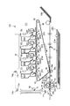
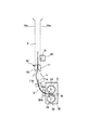
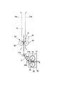
図1は、本実施例の画像形成装置100の全体構成を示す。画像形成装置100は、画像形成装置本体(以下「装置本体」という。)に通信可能に接続されたパーソナルコンピュータ、或いは原稿画像情報を光学的に読み取り電気信号に変換する原稿読み取り装置などの外部機器からの画像情報信号に従って、記録材、例えば、記録用紙、OHPシート、布などに電子写真方式を用いての4色フルカラー画像の形成が可能なカラーレーザビームプリンタである。
FIG. 1 shows an overall configuration of an
画像形成装置100は、図示のように、像形成手段として、それぞれイエロー(Y)、マゼンタ(M)、シアン(C)、ブラック(K)のトナー像を形成する4つのステーションPY、PM、PC、PKを中間転写体80の進行方向に沿って並置したタンデム方式を採用している。又、画像形成装置100は、図1に示す画像形成部101と、画像処理部120(図6)とを有する。画像形成部101においては、画像処理部が変換した露光時間に基づいて点灯する露光光により静電潜像を形成し、この静電潜像を現像して単色トナー像を形成し、この単色トナー像を重ね合わせて多色トナー像を形成し、この多色トナー像を記録材へ転写し、その記録材上の多色トナー像を定着させるようになっている。
As illustrated, the
本実施例では、画像形成装置100が備える4つのステーションPY、PM、PC、PKの構成及び動作は、形成するトナー像の色が異なることを除けば実質的に同一とされるので、以下、特に区別を要しない場合は、何れかのステーションに属する要素であることを表すように図中符号に与えた添え字Y、M、C、Kは省略して、総括的に説明する。又、本明細書において、画像形成装置100の説明で上流、下流とは、別に特段の記載の無い限り、記録材Sの搬送経路(以下「記録材搬送経路」という。)における上流、下流を意味する。
In this embodiment, the configuration and operation of the four stations PY, PM, PC, and PK included in the
ステーションPは、像担持体としての円筒状の電子写真感光体(以下「感光ドラム」という。)22を回転可能に有している。そして、この感光ドラム22の外周に沿って、一次帯電手段23、露光手段24、現像手段26、現像剤補給容器(トナーカートリッジ)25が設けられている。又、中間転写体80を介して感光ドラム22と対向するように一次転写手段27が設けられている。
The station P has a cylindrical electrophotographic photosensitive member (hereinafter referred to as “photosensitive drum”) 22 as an image bearing member so as to be rotatable. A
本実施例では、感光ドラム22は、アルミシリンダの外周に有機光導伝層を塗布して構成し、駆動モータ(図示せず)の駆動力が伝達されて回転する。この駆動モータは感光ドラム22を画像形成動作に応じて図中反時計周り方向に回転させる。 In this embodiment, the photosensitive drum 22 is configured by applying an organic optical transmission layer to the outer periphery of an aluminum cylinder, and rotates by receiving a driving force of a driving motor (not shown). This drive motor rotates the photosensitive drum 22 in the counterclockwise direction in the drawing according to the image forming operation.
又、本実施例では、一次帯電手段として、注入帯電器23を備えている。この注入帯電器23は、帯電スリーブ23Sを回転可能に有し、この帯電スリーブ23Sの表面には、感光ドラム22の表面に接触する磁気ブラシが形成される。帯電工程時には、帯電スリーブ23Sは回転すると共に所定の電圧(帯電バイアス)が印加され、感光ドラム22の表面を電荷注入帯電によりほぼ一様に所定の電位に帯電させる。
In this embodiment, an
こうして、一様に帯電された感光ドラム22の表面を、露光手段としてのスキャナ部(レーザスキャナ)24から送られる露光光によって選択的に露光することにより、感光ドラム22上に静電潜像を形成する。 In this way, the surface of the uniformly charged photosensitive drum 22 is selectively exposed by exposure light sent from a scanner unit (laser scanner) 24 as an exposure unit, whereby an electrostatic latent image is formed on the photosensitive drum 22. Form.
感光ドラム22に形成された静電潜像は、現像手段としての、乾式現像剤粒子(トナー)を用いる現像器26によってトナー像として可視化される。現像器26には、現像剤担持体としての現像スリーブ26Sが設けられており、トナーは現像スリーブ26Sによって感光ドラム22との対向部(現像部)に搬送される。現像工程時には、現像スリーブ26Sは回転すると共に所定の電圧(現像バイアス)が印加される。そして、現像スリーブ26Sと感光ドラム22との間に形成される電界によって、現像部に搬送されたトナーが、感光ドラム22上に形成された静電潜像に応じて感光ドラム22に転移する。これにより、感光ドラム22上にトナー像が形成される。現像器26には、現像剤補給容器(トナーカートリッジ)25が連結されており、使用した量に応じてトナーが補給されるようになっている。又、各ステーションPY、PM、PC、PKに設けられた各々の現像器26Y、26M、26C、26Kは装置本体に対して脱着可能に取り付けられている。
The electrostatic latent image formed on the photosensitive drum 22 is visualized as a toner image by a developing
こうして感光ドラム22上に形成されたトナー像は、感光ドラム22と中間転写体80との当接部(一次転写部)T1において、一次転写手段としての一次転写ローラ27の作用によって中間転写体80に転写される。
The toner image thus formed on the photosensitive drum 22 is transferred to the
中間転写体80は、感光ドラム22に接触しており、画像形成時には図示時計周り方向に周回移動(回転)する。本実施例では、中間転写体80は無端ベルト状の中間転写ベルトであり、複数のローラ、ここでは駆動ローラ81、テンションローラ82、二次転写対向ローラ83に掛け回されて周回移動する。
The
例えば、4色フルカラー画像の形成時には、中間転写体80は、各ステーションPY、PM、PC、PKの各々の感光ドラム22Y、22M、22C、22Kの回転に伴って周回移動し、各感光ドラム22Y、22M、22C、22K上にそれぞれ形成された単色トナー像が順次にその上に転写(一次転写)される。その後、二次転写部T2にて中間転写体80に二次転写手段としての二次転写ローラ28が接触して、記録材Sを狭持搬送し、記録材Sに中間転写体80上の多色トナー像が転写(二次転写)される。二次転写ローラ28は、記録材S上に多色トナー像を転写している間、図中28aで示す位置で記録材Sに当接し、印字処理後は図中28bで示す位置に離間する。
For example, during the formation of a four-color full-color image, the
記録材Sは、二次転写工程に先立って、給紙部としてのカセット21a或いは手差しトレイ21bから、中間転写体80上へのトナー像の形成と同期が取られて二次転写部T2へと搬送されてくる。
Prior to the secondary transfer process, the recording material S is synchronized with the formation of the toner image on the
多色トナー像が二次転写された記録材Sは、中間転写体80から分離されて、定着装置30へと搬送される。
The recording material S on which the multicolor toner image is secondarily transferred is separated from the
定着装置30は、記録材Sを搬送しながら、記録材S上に転写された多色トナー像を溶融混合して定着させる。本実施例では、定着装置30は、第1の定着部材としての定着ローラ31と、第2の定着部材としての加圧ローラ32とを有し、これら定着ローラ31と加圧ローラ32とで形成する定着ニップ部Nにて、記録材Sを挟持搬送して加熱及び加圧する。
The fixing
定着ローラ31と加圧ローラ32は中空状に形成され、内部にそれぞれ加熱手段としてハロゲンヒータなどのヒータ33、34が内蔵されている。即ち、トナー像を保持した記録材Sは定着ローラ31と加圧ローラ32により搬送されると共に、熱及び圧力を加えられ、トナーが表面に定着される。
The fixing
前述のように、多色トナー像を定着するカラー用定着装置では、多色トナー像を十分に溶融して、フルカラー画像として良好な光沢度、定着性を得るために、従来のモノクロ用定着装置に比べ、高加圧力が必要である。本実施例での定着装置30は、60kgf(≒588N)の加圧力としている。
As described above, in a color fixing device that fixes a multicolor toner image, a conventional monochrome fixing device in order to sufficiently melt the multicolor toner image and obtain good glossiness and fixability as a full color image. Compared with, high pressure is required. The fixing
又、定着装置30の記録材を移動させる速度(以下、「記録材搬送速度」と呼ぶ。)は、定着装置30よりも上流にある中間転写体80と同速とするか、又は定着装置30の記録材搬送速度を中間転写体80の記録材搬送速度より0.5〜1.0%減の速度でも良い。このようにすることで、中間転写体80と定着装置30との間での記録材Sの搬送性を安定させることができる。本実施例では、中間転写体80の記録材搬送速度を121mm/sec、定着装置30の記録材搬送速度を120mm/secとした。
The speed at which the recording material of the fixing
上記定着装置30によってトナー像を定着した後の記録材Sは、次いで、定着排出ローラ35a、35bによって定着装置30より排出される。定着排出ローラ35a、35bは、定着直後のトナー像に接触するので、その部分の光沢が他の部分に比べて変わり、画像不良として現れないように、接触圧を非常に軽圧にしている。
The recording material S after the toner image is fixed by the fixing
一方、二次転写後に中間転写体80上に残ったトナーは、クリーニング部材として中間転写体80に当接配置されたクリーニングブレードなどを有する中間転写体クリーニング手段29によってクリーニングする。これにより、中間転写体80上に形成された4色のトナー像を記録材Sに転写した後の廃トナーは、クリーナ容器(図示せず)に蓄えられる。尚、本実施例の画像形成装置100では、一次転写後に感光ドラム22上に残ったトナー像は、注入帯電器に一旦回収された後感光ドラム22上に吐き出されて現像器26に回収するクリーナレス機構とされている。勿論、従来一般に用いられているクリーニング部材としての感光ドラム22に当接配置されるクリーニングブレードなどを有する感光体クリーニング手段を設けてもよい。
On the other hand, the toner remaining on the
カラーセンサ40は、定着装置30より下流の記録材搬送経路において、記録材Sの画像形成面へ向けて配置されており、記録材S上に形成された定着後のトナー像の濃度(画像濃度)値を検出する。
The
尚、本実施例の画像形成装置100は、記録材Sの排紙経路として、図1中点線で示すフェイスダウン排紙パスAと、図1中一点鎖線で示すフェイスアップ排紙パスBを有する。後述カラーセンサ40を使用した濃度階調制御を実行する際は、フェイスダウン排紙パスAを使用する。
The
フェイスダウン排紙パスAにおいて、定着装置30から排出されてくる記録材Sは、搬送ローラ71a、71bにより、カラーセンサ40に搬送される。搬送ローラ71a、71bは、定着直後のトナー像に接触するので、その部分の光沢が他の部分に比べて変わって、画像不良として現れてしまわないように、接触圧を非常に軽圧にしている。
In the face-down paper discharge path A, the recording material S discharged from the fixing
次いで、記録材Sはカラーセンサ40を通過後、搬送ローラ72a、72b、及び73a、73bにより、記録材排出部たるフェイスダウン排紙トレイ81上に排出され、画像形成動作が終了する。
Next, after the recording material S passes through the
[カラーセンサ]
次に、本実施例にて用いたカラーセンサについて更に詳しく説明する。
[Color sensor]
Next, the color sensor used in this embodiment will be described in more detail.
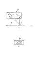
図2Aにカラーセンサ40の構成の一例を示す。本実施例では、カラーセンサ40は、発光素子としての白色LED(以下、単に「発光素子」という。)41と、受光素子としてのRGBオンチップフィルタ付き電荷蓄積型センサ(以下、単に「受光素子」という。)42とを有して構成される。発光素子41からの光(検知光)を、定着後のパッチ11が形成された記録材Sに対して斜め45度より入射させ、0度方向への受光素子42により検知する。図2Bに示すように、受光素子42の受光部は、RGBが独立した画素42aとなっている。
FIG. 2A shows an example of the configuration of the
尚、受光素子42が備える電荷蓄積型センサは、フォトダイオードでも良い。又、RGBの3画素のセットが、数セット並んでいるものでも良い。又、入射角が0度で、反射角が45度の構成でも良い。更には、RGB3色を発光するLEDとフィルタ無しセンサにより構成しても良い。
The charge storage type sensor provided in the
[画像形成条件制御]
次に、本実施例における画像形成条件制御について図3のフローチャートを参照して説明する。
[Image formation condition control]
Next, image forming condition control in this embodiment will be described with reference to the flowchart of FIG.
本実施例では、定着後のトナー像の光反射特性を検出して行う画像形成条件制御として、画像の濃度階調制御を行う。尚、本実施例の濃度階調制御は、カラーセンサ40を使用して階調補正デーブル(LUT)を求め、画像情報信号を補正する画像階調補正制御(以下「階調補正制御」という。)である。又、この階調補正制御は、本実施例では、濃度階調特性の変動が想定される、装置本体の電源ON時、及び現像装置26、感光ドラム22の交換時に実施される。又、操作者が所望した場合に、装置本体或いは装置本体に通信可能に接続された外部機器が備える入力手段を介した操作者の手動操作によっても実施し得るものとする。
In this embodiment, image density gradation control is performed as image formation condition control performed by detecting the light reflection characteristics of the toner image after fixing. In the density gradation control of this embodiment, the gradation correction table (LUT) is obtained by using the
(STEP1)
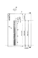
先ず、記録材S上に複数のパッチ11からなるパッチパターン10を形成する。図4は、記録材S上(本例では、297mm×420mmのA3サイズ縦送り:記録材11の長手方向に沿って搬送)に形成される本実施例のパッチパターン10を示している。即ち、本例では、カラーセンサ40の配置されている部分に8mm角のパッチ11が10mm間隔(パッチ間は2mm)で、Y、M、C、K毎に画像印字率(濃度階調度)を8段階に変化させて(各色8パッチずつ)、合計32個形成される。又、本例では、パッチ11が形成される領域(以下「パッチ形成領域」という。)H、即ち、記録材Sの搬送方向において先頭のパッチ11(Y1パッチ)の先端から、最後のパッチ11(K8パッチ)の後端までの長さHは318mmである。又、記録材Sの搬送方向においてパッチ形成領域Hの前には先端余白F(87mm)、後ろには後端余白R(15mm)が設けられている。即ち、パッチの印字開始位置は、記録材S上の先端87mmからである。各パッチ11と印字率(階調度)との対応は、
Y1,M1,C1,K1=12.5%
Y2,M2,C2,K2=25%
Y3,M3,C3,K3=37.5%
Y4,M4,C4,K4=50%
Y5,M5,C5,K5=62.5%
Y6,M6,C6,K6=75%
Y7,M7,C7,K7=87.5%
Y8,M8,C8,K8=100%
に設定されている。
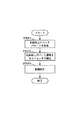
(STEP1)
First, a
Y1, M1, C1, K1 = 12.5%
Y2, M2, C2, K2 = 25%
Y3, M3, C3, K3 = 37.5%
Y4, M4, C4, K4 = 50%
Y5, M5, C5, K5 = 62.5%
Y6, M6, C6, K6 = 75%
Y7, M7, C7, K7 = 87.5%
Y8, M8, C8, K8 = 100%
Is set to
(STEP2)
次に、記録材に定着されたパッチ11の濃度をカラーセンサ40によって検出する。尚、カラーセンサ40の検知信号を濃度に変換する方法は、公知の検知信号対濃度の変換テーブル(濃度変換テーブル)を用いる方式である。この変換テーブルは、後述する画像処理部120の記憶手段122に記憶されている。
(STEP2)
Next, the
(STEP3)
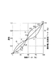
次いで、階調補正制御を実施する。以下、図5を参照して階調補正制御について更に説明する。尚、ここでは、シアン色の階調補正についてのみ説明するが、マゼンタ、イエロー、ブラックに関しても同様の方法で補正が行われる。
(STEP3)
Next, gradation correction control is performed. Hereinafter, the gradation correction control will be further described with reference to FIG. Here, only cyan tone correction will be described, but magenta, yellow, and black are also corrected in the same manner.
図5中、横軸は画像データを表している。又、縦軸(左側)は、カラーセンサ40の濃度検出値を表している。そして、図中○印は、C1、C2、C3、C4、C5、C6、C7、C8の各パッチ11に対するカラーセンサの出力濃度値を表している。
In FIG. 5, the horizontal axis represents image data. The vertical axis (left side) represents the density detection value of the
直線Tは、画像濃度制御の目標濃度階調特性を表す。これに限定されるものではないが、本実施例では、画像データと濃度の関係が比例関係になるように目標濃度階調特性Tを定めた。又、曲線γは、階調補正制御を実施していない状態での濃度階調特性を表す。尚、パッチ11を形成していない階調の濃度については、原点及びC1、C2、C3、C4、C5、C6、C7、C8の各点を通るように公知のスプライン補間を行い算出される。
A straight line T represents a target density gradation characteristic for image density control. Although not limited to this, in this embodiment, the target density gradation characteristic T is determined so that the relationship between the image data and the density is proportional. A curve γ represents density gradation characteristics when gradation correction control is not performed. It should be noted that the gradation density not forming the
曲線Dは、本制御で算出される階調補正テーブルを表しており、補正前の濃度階調特性γの目標濃度階調特性Tに対する対称ポイントを求めることにより算出される。図5の縦軸(右側)は、階調補正後の画像データ(%)を示す。 A curve D represents a gradation correction table calculated by this control, and is calculated by obtaining a symmetric point with respect to the target density gradation characteristic T of the density gradation characteristic γ before correction. The vertical axis (right side) in FIG. 5 shows the image data (%) after gradation correction.
尚、曲線D、即ち、階調補正テーブルDの計算は、装置本体の画像処理部120が備える画像処理制御手段たるCPU121(後述)で実行され、更に、算出された階調補正テーブルDは、同画像処理部120が備える記憶手段(本実施例では不揮発性メモリを使用した。)122(後述)に記憶される。
Note that the calculation of the curve D, that is, the gradation correction table D, is executed by a CPU 121 (described later) which is an image processing control unit included in the
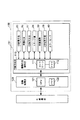
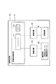
更に説明すると、図6は、本実施例の画像形成装置100における画像形成条件制御(階調補正制御)の制御態様を示す概略制御ブロック図である。画像形成装置100は、画像形成部101と、画像処理部120とを有する。
More specifically, FIG. 6 is a schematic control block diagram showing a control mode of image forming condition control (tone correction control) in the
画像処理部120は画像処理制御手段としてのCPU121と、記憶手段122とを有する。記憶手段122としては利用可能なものを特に制限なく用いることができるが、電子的なメモリが好ましい(本実施例では不揮発性メモリを用いた。以下、「メモリ」という。)。画像処理部120は、装置本体に対して通信可能に接続されたパーソナルコンピュータ、原稿読み取り装置などの外部機器からの画像信号を受信すると共に、メモリ122に記憶されたプログラム、データに従って、画像形成部101の画像形成制御部110に画像形成に係る信号を送信する。又、上記階調補正テーブルDは、画像処理部120のメモリ122に記憶される。そして、この階調補正テーブルDは、画像処理部120が受信した画像信号をレーザ露光により感光ドラム22上に静電潜像を形成する基となる画像信号を補正するために用いられる。
The
画像形成部101は、画像形成装置100の各部を制御する画像形成制御部110を有する。画像形成制御部110は、画像形成制御手段としてのコントローラ111と記憶手段112とを有する。記憶手段122としては利用可能なものを特に制限なく用いることができるが、電子的なメモリが好ましい(本実施例では不揮発性メモリを用いた。以下、「メモリ」という。)。コントローラ111は、メモリ112に記憶されたプログラム、データに従って、一次帯電手段23、スキャナ部24、現像手段26、一次転写手段27、二次転写手段28、定着装置30、カラーセンサ40などを制御する。カラーセンサ40の検出信号は、画像形成制御部110へ入力されると共に、画像形成制御部110を介して画像処理部120へ入力され、画像信号の補正に使用する階調補正テーブルDを調整するための情報として用いられる。又、コントローラ111は、感光ドラム22、中間転写体80、定着装置30の定着ローラ31及び加圧ローラ32、及び定着排出ローラ35a、35b、搬送ローラ71a、71b、72a、72b、73a、73bなどを駆動する駆動装置としての駆動モータ(図示せず)を制御する。
The
図3を再度参照して、階調補正制御を実施するに当たり、画像形成制御部110のコントローラ111は、階調補正制御をすべきコマンドを受信すると、記録材Sに上述のパッチパターン10を形成させ、これを定着させて、フェイスダウン排紙パスAへと搬送させる(STEP1)。そして、画像形成制御部110のコントローラ111は、記録材S上の各パッチ11をカラーセンサ40により検出して受信した検出信号を、画像処理部120のCPU121へ送る(STEP2)。そして、画像処理部120のCPU121が、カラーセンサ40から画像形成制御部110を介して受信した検知結果に基づいて階調補正テーブルDを調整(算出)し、画像処理部120のメモリ122に記憶させる(STEP3)。
Referring again to FIG. 3, when performing the gradation correction control, the
このように、本実施例では、画像処理制御手段たるCPU121が、画像形成条件制御手段の機能を有する。
As described above, in this embodiment, the
通常の出力画像(プリント画像)の形成時は、画像データを階調補正テーブルDで補正することにより、目標濃度階調特性を得ることができる。斯かる画像データの補正方法自体は公知であり、又本発明においては任意の方法を採用し得るので詳しい説明は省略するが、一例として、概略、次のような方法で行うことができる。画像処理部120のメモリ122に、上記階調補正テーブルDの他、カラーマッチングテーブル、色分解テーブル、PWMテーブルの各補正テーブルを記憶させる。そして、予め用意されているカラーマッチングテーブルにより、外部機器から送られてくる画像の色を表すRGB信号を所定の補正係数を用いた演算により補正し、画像形成装置100の色再現域に合わせたデバイスRGB信号(以下「DevRGB」という。)に変換する。又、予め用意されている色分解テーブルにより、DevRGB信号を所定の補正係数を用いた演算により補正し、画像形成装置100のトナー色材色であるCMYK信号に変換する。更に、各々の画像形成装置に固有の濃度−階調特性を補正する階調補正テーブルDにより、CMYK信号を所定のテーブルを用いて演算することにより、濃度−階調特性の補正を加えたC'M'Y'K'信号へ変換する。そして、PWM(パルス幅変調:Pulse Width Modulation)テーブルにより、C'M'Y'K'信号を所定の補正係数を用いた演算により補正し、C'M'Y'K'信号に対応する各ステーションPY、PM、PC、PKのスキャナ部27の露光時間へ変換する。このようにして、外部機器から入力された画像信号をスキャナ部27におけるレーザ露光時間に変換することができる。
When a normal output image (print image) is formed, the target density gradation characteristics can be obtained by correcting the image data with the gradation correction table D. Such an image data correction method is known per se and any method can be adopted in the present invention, so that detailed description thereof will be omitted. However, as an example, it can be roughly performed by the following method. In addition to the gradation correction table D, the color matching table, the color separation table, and the PWM table are stored in the
[カラーセンサの検出位置での記録材の搬送性]
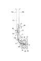
次に、図7及び図8を参照して、本実施例において最も特徴的な、カラーセンサ40の検出位置Gの近傍での記録材Sの搬送態様について説明する。
[Conveyance of recording material at the detection position of the color sensor]
Next, with reference to FIG. 7 and FIG. 8, the conveyance mode of the recording material S in the vicinity of the detection position G of the
前述のように、カラーセンサ40と記録材Sとの間の距離が不安定であると、カラーセンサ40の検出精度が悪化してしまい、良好な画像形成条件制御(本実施例では階調補正制御)ができなくなる虞がある。
As described above, if the distance between the
ここで、記録材搬送経路におけるカラーセンサ40の検出位置Gと定着ニップNとの距離を記録材Sの長さ以上にすれば、カラーセンサ40によるパッチ11の検出時に記録材Sは定着ニップNから排出される。つまり、カラーセンサ40によるパッチ11の検出時に記録材Sが定着ローラ31と加圧ローラ32とで挟持搬送されていないことになるので、カラーセンサ40と記録材Sとの距離が定着装置30の影響を受けることはない。
Here, if the distance between the detection position G of the
しかし、上記のように記録材搬送経路におけるカラーセンサ40の検出位置Gと定着ニップNとの距離を記録材Sの長さより長くするために、カラーセンサ40をより下流に設けようとすると、記録材搬送経路が長くなることなど、画像形成装置100の大型化に繋がる。
However, if the
そこで、画像形成装置100の小型化を図るためにカラーセンサ40をより定着装置30に近づけようとすると、パッチ11を形成可能な記録材Sのサイズのいずれか又は全てに関し、記録材搬送経路におけるカラーセンサ40の検出位置Gと定着ニップNとの間の距離が記録材Sの長さ以下となる場合が生じる。
Therefore, if the
そこで、本実施例では、記録材搬送経路におけるカラーセンサ40の検出位置Gと定着ニップNとの間の距離が記録材Sの長さ以下となる記録材Sにパッチ11を形成し、これをカラーセンサ40で検出する場合においても、カラーセンサ40がパッチ11を検出するときに記録材Sが定着ニップNにない、即ち、記録材Sが定着ニップNから排出されており、記録材Sが定着ローラ31と加圧ローラ32とで挟持搬送されていない構成とする。
Therefore, in the present embodiment, the
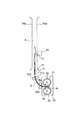
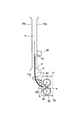
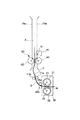
更に説明すると、図7は記録材Sが定着ニップNで挟持搬送されているときの記録材Sの搬送状態を示す。又、図8は記録材Sが定着ニップNから排出されたときの記録材Sの搬送状態を示す。 More specifically, FIG. 7 shows a conveyance state of the recording material S when the recording material S is nipped and conveyed by the fixing nip N. FIG. 8 shows the conveyance state of the recording material S when the recording material S is discharged from the fixing nip N.
図中Hは、記録材S上のパッチ形成領域を表す。又、図中L(点線)は、記録材搬送経路におけるカラーセンサ40の検出位置Gから定着ニップNの下流側までの距離を表す。
In the figure, H represents a patch forming area on the recording material S. In the drawing, L (dotted line) represents the distance from the detection position G of the
図4をも参照して、本実施例の画像形成装置100では、パッチ11を形成して階調補正制御に使用する記録材Sのサイズ(種類)は変更可能である。本実施例では、パッチ11を形成可能な記録材Sの最大値はA3サイズ(縦送り)である。そして、本実施例の画像形成装置100では、画像形成装置100の小型化を図るために、定着装置30より下流の記録材搬送経路(フェイスダウン排紙パスA)の構成によって、少なくともA3サイズ(縦送り)の場合には、記録材搬送経路におけるカラーセンサ40の検出位置Gと定着ニップNとの間の距離が記録材Sの長さX以下となる。即ち、カラーセンサ40の検出位置Gから定着ニップNの下流側までの距離Lは、本実施例では、A3サイズ(297mm×420mmの縦送り)に対応する、L<420mmとなっている。
Referring also to FIG. 4, in the
一方、記録材搬送経路におけるカラーセンサ40の検出位置Gから定着ニップNの下流側までの距離Lの下限値は、記録材Sが定着ニップNから排出された後にY1パッチを検出位置Gに到達させるために、記録材Sのサイズ、パッチ11の大きさにより変わる。
On the other hand, the lower limit of the distance L from the detection position G of the
例えば、A3サイズ縦送りで、図4に示したパッチパターン10を使用した場合、パッチ形成領域H(318mm)と記録材Sの後端余白(15mm)から、333mm<Lとなる。即ち、記録材搬送経路におけるカラーセンサ40の検出位置Gから定着ニップNの下流側までの距離Lは、記録材Sの搬送方向における先頭のパッチ11(Y1パッチ)の先端から記録材Sの後端までの長さI(333mm)より長くする。ここでは、距離Lを350mmとした。
For example, when the
上記距離L>長さIなる関係を満足するために、カラーセンサ40の配置を設定するのみならず、記録材S上に形成するパッチ11の配置、大きさなどを設定することができる。
In order to satisfy the relationship of distance L> length I, not only the arrangement of the
図7に示すように、記録材Sが定着装置30の定着ニップNで挟持搬送されているときには、記録材Sは定着装置30からの振動を受け、記録材Sとカラーセンサ40との距離が不安定になってしまう。
As shown in FIG. 7, when the recording material S is nipped and conveyed by the fixing nip N of the fixing
しかし、本実施例では、距離Lと長さIとを上記の如く設定したので、カラーセンサ40がパッチ11を検出するとき、記録材Sが定着ニップNにない、即ち、記録材Sが定着ニップNから排出されており、記録材Sが定着ローラ31と加圧ローラ32とで挟持搬送されていない。従って、記録材Sは定着装置30からの影響を受けないので、図8に示すように、カラーセンサ40によるパッチ11の検出時には、カラーセンサ40の検出位置Gにおいて記録材Sの搬送性は安定する。このように、上記構成により、記録材Sとカラーセンサ40との距離を安定させて、カラーセンサ40によるパッチ11の検出精度を高めて、良好な画像形成条件制御(本実施例では階調補正制御)を行うことができる。
However, in this embodiment, since the distance L and the length I are set as described above, when the
以上、本実施例によれば、記録材S上に形成された定着後の制御用トナー像11の光反射特性を光学式センサ40により検出して、その検出結果に応じて画像形成条件を制御する画像形成条件制御手段121を有し、制御用トナー像11を形成可能な少なくとも1つの所定の記録材Sに関して記録材搬送経路における光学式センサ40の検出位置Gと定着ニップNとの距離Lが当該所定の記録材Sの長さ以下となる画像形成装置100は、光学式センサ40が当該所定の記録材Sに形成された制御用トナー像11の光反射特性を検出するときに、定着ニップN当該所定の記録材Sがない構成とする。
As described above, according to the present exemplary embodiment, the light reflection characteristic of the
これにより、光学式センサ40付近の記録材Sの搬送性を安定させることができる。そして、光学式センサ11による定着後の制御用トナー像11の検出精度を高め、良好な画像形成条件制御を行うことができる。その結果、カラー画像の色安定性を向上することができる。又、本実施例によれば、画像形成装置100を大型化することなく、これらの効果を達成し得る。つまり、制御用トナー像11の光反射特性検知の安定化と画像形成装置の小型化とを両立することができる。
Thereby, the transportability of the recording material S in the vicinity of the
実施例2
次に、本発明の他の実施例について説明する。尚、本実施例の画像形成装置の全体構成、及び画像濃度制御の方法自体は、実施例1で説明したものと実質的に同一であり、カラーセンサと記録材の距離を安定させるための規制部材をカラーセンサの上流側に配置したことが異なる。従って、ここでは、実施例1の画像形成装置100と同一若しくは相当する構成、機能を有する要素には同一符号を付して詳しい説明は省略する。
Example 2
Next, another embodiment of the present invention will be described. The overall configuration of the image forming apparatus of the present embodiment and the image density control method itself are substantially the same as those described in the first embodiment, and the regulations for stabilizing the distance between the color sensor and the recording material. The difference is that the members are arranged upstream of the color sensor. Therefore, here, elements having the same or corresponding configurations and functions as those of the
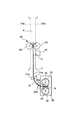
以下、図9を参照して、本実施例において最も特徴的な、カラーセンサ40の検出位置Gの近傍での記録材Sの搬送態様について説明する。
Hereinafter, with reference to FIG. 9, the conveyance mode of the recording material S in the vicinity of the detection position G of the
本実施例では、実施例1と同様に、パッチ11を形成可能な記録材Sのサイズのいずれか又は全てに関し、記録材搬送経路におけるカラーセンサ40の検出位置Gと定着ニップNとの間の距離が記録材Sの長さ以下となる。
In the present exemplary embodiment, as in the first exemplary embodiment, regarding any or all of the size of the recording material S on which the
そこで、本実施例では、カラーセンサ40の上流側に、記録材Sの位置を規制する(安定させる)規制部材50を配置する。
Therefore, in this embodiment, a regulating
この規制部材50の位置は、記録材搬送経路におけるカラーセンサ40の検出位置Gと定着ニップNとの間の距離が記録材Sの長さ以下となる記録材Sにパッチ11を形成してこれをカラーセンサ40で検出する場合において、カラーセンサ40がパッチ11の少なくとも一部(通常、記録材Sの先端側の一部)を検出するときに、定着ニップNと当該規制部材50とで共に記録材Sを挟持し得る位置である。特に、本実施例は、記録材搬送経路におけるカラーセンサ40の検出位置Gから定着ニップNの下流側までの距離Lが、記録材Sの搬送方向における先頭のパッチ11(Y1パッチ)の先端から記録材Sの後端までの長さIより短くなる場合に有効である。但し、検出位置Gでの記録材Sの安定性の観点から、好ましくはカラーセンサ40の上流に5mm〜50mm、より好ましくは10mm〜30mmに設けることで、好結果が得られる。
The position of the regulating
更に説明すると、図9は、記録材Sと、カラーセンサ40、定着ニップN及び規制部材50との位置関係を示す。規制部材50は、第1の規制部として記録材表面規制部材(以下「表面規制部材」という。)51と、第2の規制部としての記録材裏面規制部材(以下「裏面規制部材」という。)52とを有し、定着装置30の下流、且つ、カラーセンサ40の上流側(本実施例では、フェイスダウン排紙パスA内)に配置されている。
More specifically, FIG. 9 shows the positional relationship between the recording material S, the
規制部材50は、図9に示すように記録材Sが定着ニップNで挟持搬送されていても、記録材Sをカラーセンサ40の直前で規制して安定させる。表面規制部材51及び裏面規制部材52は共に、好ましくは、POM(ポリオキシメチレン)、PC(ポリカーボネイト)、PC+ABS(ポリカーボネイト+アクリルロニトリル ブタジエン スチレン共重合体、PET(ポリエチレンテレフタレート)などの摺動性の高い樹脂材(摺動部材)で形成する。
The regulating
そして、好ましくは、表面規制部材51と裏面規制部材52とは当接させる。その当接圧は0〜10gf(≒0〜0.098N)が好ましく、より好ましくは、3〜5gf(≒0.0294N〜0.049N)とする。本実施例では5gf(≒0.049N)とした。当接圧が10gf(0.098N)より大きいと、図10に示すように搬送の負荷となり、記録材Sが規制部材50の上流側で弛んで、ループ量が大きくなり過ぎる。これにより、記録材Sが搬送路(搬送ガイド)70aなどに接触し、光沢ムラ、傷などの画像不良を発生させることがある。又、当接圧が0gより小さい、即ち、表面規制部材51と裏面規制部材52が当接していないと、図11に示すように記録材Sが定着ニップNに挟持搬送されているとき、記録材Sとカラーセンサ40の距離が不安定になることがある。
Preferably, the front
尚、本実施例では、表面規制部材51と裏面規制部材52は常に接触させているが、カラーセンサ40で記録材S上のトナー濃度を検出するときにだけ当接させても良い。この場合、画像形成制御部110のコントローラ111がメモリ112に記憶されたプログラム、データに従って、表面規制部材51と裏面規制部材52とを当接/離間させる駆動手段(図示せず)の駆動を制御する。そして、所定のタイミングでこれら表面規制部材51と裏面規制部材52とを当接させればよい。この所定のタイミングは、少なくとも記録材搬送経路におけるカラーセンサ40の検出位置Gと定着ニップNとの間の距離が記録材Sの長さ以下となる記録材Sにパッチ11を形成してこれをカラーセンサ40で検出するとき(特に、そのとき記録材Sが定着ニップNにある間)を含む。
In this embodiment, the front
以上、本実施例によれば、記録材S上に形成された定着後の制御用トナー像11の光反射特性を光学式センサ40により検出して、その検出結果に応じて画像形成条件を制御する画像形成条件制御手段121を有し、制御用トナー像11を形成可能な少なくとも1つの所定の記録材Sに関して記録材搬送経路における光学式センサ40の検出位置Gと定着ニップNとの距離Lが当該所定の記録材Sの長さ以下となる画像形成装置100は、光学式センサ40の上流側に記録材Sの位置を安定させる規制部材40が配置された構成とする。そして、この規制部材40は、前記所定の記録材Sに形成された制御用トナー像11の少なくとも一部の光反射特性を光学式センサ40で検出するときに、定着ニップNと当該規制部材40とで共に前記所定の記録材Sを挟持するように配置する。
As described above, according to the present exemplary embodiment, the light reflection characteristic of the
これにより、実施例1と同様の効果が得られると共に、記録材搬送経路における光学式センサ40の検出位置Gと定着ニップNとの間の距離が記録材Sの長さ以下となる記録材Sに制御用トナー像11を形成してこれを光学式センサ40で検出する場合にも、距離Lは長さIより短くてよく、光学式センサ40の配置自由度が増す。例えば、光学式センサ40を実施例1と比較して更に上流に配置して、定着装置30より下流の記録材搬送経路(フェイスダウン排紙パスA)を短くするなどして、画像形成装置100を更に小型化することができる。又、記録材Sに形成する制御用トナー像11の配置、大きさの自由度も向上する。
As a result, the same effect as in the first embodiment is obtained, and the recording material S in which the distance between the detection position G of the
実施例3
次に、本発明の他の実施例について説明する。尚、本実施例の画像形成装置の全体構成、及び画像濃度制御の方法自体は、実施例1及び実施例2で説明したものと実質的に同一であり、実施例2における規制部材50に替えて、カラーセンサと記録材の距離を安定させるための搬送部材をカラーセンサの上流側に配置することが異なる。従って、ここでは、実施例1の画像形成装置100と同一若しくは相当する構成、機能を有する要素には同一符号を付して詳しい説明は省略する。
Example 3
Next, another embodiment of the present invention will be described. The overall configuration of the image forming apparatus of the present embodiment and the image density control method itself are substantially the same as those described in the first and second embodiments, and are replaced with the regulating
以下、図12及び図13を参照して、本実施例において最も特徴的な、カラーセンサ40の検出位置Gの近傍での記録材Sの搬送態様について説明する。
Hereinafter, with reference to FIGS. 12 and 13, the conveyance mode of the recording material S in the vicinity of the detection position G of the
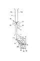
本実施例では、カラーセンサ40の上流側に、記録材Sの搬送性を安定させる搬送部材60を配置する。
In the present embodiment, a
この搬送部材60の位置は、実施例2における規制部材50と同様、記録材搬送経路におけるカラーセンサ40の検出位置Gと定着ニップNとの間の距離が記録材Sの長さ以下となる記録材Sにパッチ11を形成してこれをカラーセンサ40で検出する場合において、カラーセンサ40がパッチ11の少なくとも一部(通常、記録材Sの先端側の一部)を検出するときに、定着ニップNと当該搬送部材60とで共に記録材Sを挟持する位置である。その他、搬送部材60の配置設定は、実施例2の規制部材50の場合に準じる。
As with the regulating
尚、この搬送部材60が、実施例2にて説明した記録材Sの位置を規制する規制部材50の機能をも兼ねていることは容易に理解されよう。
It will be easily understood that the conveying
そして、好ましくは、搬送部材60の記録材搬送速度は、定着装置30の記録材搬送速度より低速とする。
Preferably, the recording material conveyance speed of the
更に説明すると、図12は、記録材Sと、カラーセンサ40、定着ニップN及び搬送部材60との位置関係を示す。搬送部材60は、第1の搬送部としての回転体(第1の回転体)である記録材表面搬送ローラ(以下「表面搬送ローラ」という。)61と、第2の搬送部としての回転体(第2の回転体)である記録材裏面搬送ローラ(以下「裏面搬送ローラ」という。)62とを有し、定着装置30の下流、且つ、カラーセンサ40の上流側(本実施例では、フェイスダウン排紙パスA内)に配置されている。表面搬送ローラ61と裏面搬送ローラ62は、互いに当接して回転することで、その当接部に導入された記録材Sを挟持して搬送する。
More specifically, FIG. 12 shows the positional relationship among the recording material S, the
ここで、上述のように、好ましくは、搬送部材60の記録材搬送速度は、定着装置30の記録材搬送速度より低速とする。本実施例では、搬送部材60は記録材搬送速度119mm/secで矢印方向に回転する。定着装置30の記録材搬送速度は、前述の通り120mm/secである。定着装置30の記録材搬送速度に対し搬送部材60の記録材搬送速度を低速にしているのは、図12に示すように記録材Sをカラーセンサ40の直前で規制して安定させるためである。
Here, as described above, the recording material conveyance speed of the
本発明者らの検討によれば、搬送部材60の良好な記録材搬送性を得るためには、搬送部材60の記録材搬送速度を定着装置30の記録材搬送速度の0.5〜1.0%減の速度にすることが好ましく、より好ましくは、0.6〜0.8%減である。0.5%減未満だと(即ち、0.5%減の速度より高速であると)、速度差が小さ過ぎて、図14に示すように記録材Sを引っ張って搬送してしまい、ループ量がなくなる。これにより、記録材Sを定着排紙ローラ35a及び排紙ローラ71aなどに摺擦して、光沢ムラ、傷などの画像不良を発生させてしまうことがある。又、1.0%減より大きいと(即ち、1.0%減の速度より低速であると)、速度差が大き過ぎて、図15に示すように記録材Sが搬送部材60の上流側で弛んで、ループ量が大き過ぎてしまう。このため、記録材Sが搬送路(搬送ガイド)70aなどに接触し光沢ムラ、傷などの画像不良を発生させることがある。
According to the studies by the present inventors, in order to obtain good recording material transportability of the
図13は、本実施例における搬送部材60と定着装置30の記録材搬送速度制御のブロック図である。本実施例では、定着装置30と搬送部材60とは、それぞれ画像形成制御部110のコントローラ111の制御で、異なる駆動装置91、92から動力を得て、異なる記録材搬送速度で記録材Sを搬送し得る。コントローラ111は、画像形成制御部110が備えるメモリ112に記憶されたプログラム、データに従って、駆動装置91、92を駆動制御し、所定タイミングで搬送部材60の記録材搬送速度と定着装置30の記録材搬送速度とを異ならせる。この所定のタイミングは、少なくとも記録材搬送経路におけるカラーセンサ40の検出位置Gと定着ニップNとの間の距離が記録材Sの長さ以下となる記録材Sにパッチ11を形成してこれをカラーセンサ40で検出するとき(特に、そのとき記録材Sが定着ニップNにある間)を含む。勿論、搬送部材60の記録材搬送速度と定着装置30の記録材搬送速度は、常に異ならせても良い。
FIG. 13 is a block diagram of recording material conveyance speed control of the
以上、本実施例によれば、記録材S上に形成された定着後の制御用トナー像11の光反射特性を光学式センサ40により検出して、その検出結果に応じて画像形成条件を制御する画像形成条件制御手段121を有し、制御用トナー像11を形成可能な少なくとも1つの所定の記録材Sに関して記録材搬送経路における光学式センサ40の検出位置Gと定着ニップNとの距離Lが当該所定の記録材Sの長さ以下となる画像形成装置100は、光学式センサ40の上流側に記録材Sの搬送性を安定させる搬送部材60が配置された構成とする。そして、この搬送部材60は、前記所定の記録材Sに形成された制御用トナー像11の少なくとも一部の光反射特性を光学式センサで検出するときに、定着ニップNと当該規制部材40とで共に前記所定の記録材Sを挟持するように配置する。又、好ましくは、搬送部材60の記録材Sを移動させる速度が定着装置30の記録材Sを移動させる速度より低速であるようにする。
As described above, according to the present exemplary embodiment, the light reflection characteristic of the
これにより、実施例1及び実施例2と同様の効果が得られると共に、特に、本実施例では、カラーセンサ40の検出位置Gで記録材Sの搬送性向上の効果がある。
As a result, the same effects as those of the first and second embodiments can be obtained, and in particular, the present embodiment has an effect of improving the transportability of the recording material S at the detection position G of the
実施例4
次に、本発明の更に他の実施例について説明する。尚、本実施例の画像形成装置の全体構成、及び画像濃度制御の方法自体は、実施例1及び実施例3で説明したものと実質的に同一であり、カラーセンサと記録材の距離を安定させるための搬送部材をカラーセンサの下流側に配置することが異なる。従って、ここでは、実施例1及び実施例3の画像形成装置100と同一若しくは相当する構成、機能を有する要素には同一符号を付して詳しい説明は省略する。
Example 4
Next, still another embodiment of the present invention will be described. The overall configuration of the image forming apparatus of this embodiment and the image density control method itself are substantially the same as those described in
以下、図16を参照して、本実施例において最も特徴的な、カラーセンサ40の検出位置Gの近傍での記録材Sの搬送態様について説明する。
Hereinafter, with reference to FIG. 16, the conveyance mode of the recording material S in the vicinity of the detection position G of the
本実施例では、カラーセンサ40の下流側に、記録材Sの搬送性を安定させる搬送部材60を配置する。尚、この搬送部材60は、記録材Sの位置を規制する機能をも兼ねている。
In this embodiment, a
この搬送部材60の位置は、記録材搬送経路におけるカラーセンサ40の検出位置Gと定着ニップNとの間の距離が記録材Sの長さ以下となる記録材Sにパッチ11を形成してこれをカラーセンサ40で検出する場合において、カラーセンサ40がパッチ11の少なくとも一部(通常、記録材Sの先端側の一部)を検出するときに、定着ニップNと当該搬送部材60とで共に記録材Sを挟持する位置である。搬送部材60はカラーセンサ40より下流側に、先端余白F(図4)より離れないように配置することで、記録材Sの搬送方向において先頭のパッチ11の先端から安定した検出が可能となる。又、実施例2と同様、特に、本実施例は、記録材搬送経路におけるカラーセンサ40の検出位置Gから定着ニップNの下流側までの距離Lが、記録材Sの搬送方向における先頭のパッチ11(Y1パッチ)の先端から記録材Sの後端までの長さIより短くなる場合に有効である。但し、検出位置Gでの記録材Sの安定性の観点から、好ましくはカラーセンサ40より下流に5mm〜50mm、より好ましくは10mm〜30mmに設けることで、好結果が得られる。
The
そして、好ましくは、搬送部材60の記録材搬送速度は、定着装置30の記録材搬送速度より高速とする。
Preferably, the recording material conveyance speed of the
更に説明すると、図16は、記録材Sと、カラーセンサ40、定着ニップN及び搬送部材60との位置関係を示す。図示する通り、本実施例では、搬送部材60は、カラーセンサ40の下流側に配置されている。
More specifically, FIG. 16 shows the positional relationship among the recording material S, the
ここで、上述のように、好ましくは、搬送部材60の記録材搬送速度は、定着装置30の記録材搬送速度より高速とする。本実施例では、搬送部材60は、記録材搬送速度121mm/secで矢印方向に回転する。定着装置30の記録材搬送速度は、前述の通り120mm/secである。定着装置30の記録材搬送速度に対し搬送部材60は記録材搬送速度を若干高速にしているのは、図16に示すように記録材Sを引っ張り、カラーセンサ40部分で記録材Sを安定して搬送させるためである。
Here, as described above, the recording material conveyance speed of the
本発明者らの検討によれば、定着装置30の記録材搬送速度に対して、搬送部材60の良好な記録材搬送性を得るためには、搬送部材60の記録材搬送速度を定着装置30の記録材搬送速度の0.5〜1.0%増の速度にすることが好ましく、より好ましくは、0.6〜0.8%増である。0.5%増未満だと(即ち、0.5%増の速度より低速であると)、速度差が小さ過ぎて、図17に示すようにループ量が大きくなり、記録材Sが弛んでしまう。これにより、カラーセンサ40近傍で記録材Sが不安定になることがある。又、1.0%増より大きいと(即ち、1.0%増の速度より高速度であると)、速度差が大き過ぎて、図18に示すように記録材Sが引っ張られて、ループ量がなくなる。これにより、記録材Sが定着排紙ローラ35a及び排紙ローラ71aなどに摺擦して光沢ムラ、傷などの画像不良を発生させることがある。
According to the study by the present inventors, in order to obtain good recording material conveyance performance of the
本実施例では、実施例3と同様、図13に示すように、定着装置30と搬送部材60とは、それぞれ画像形成制御部110のコントローラ111の制御で、異なる駆動装置91、92から動力を得て、異なる記録材搬送速度で記録材Sを搬送し得る。実施例3と同様、搬送部材60の記録材搬送速度は、所定のタイミングで定着装置30の記録材搬送速度と異ならせても良いし、常に異ならせてもよい。
In the present exemplary embodiment, as in the third exemplary embodiment, as illustrated in FIG. 13, the fixing
以上、本実施例によれば、記録材S上に形成された定着後の制御用トナー像11の光反射特性を光学式センサ40により検出して、その検出結果に応じて画像形成条件を制御する画像形成条件制御手段121を有し、制御用トナー像11を形成可能な少なくとも1つの所定の記録材Sに関して記録材搬送経路における光学式センサ40の検出位置Gと定着ニップNとの距離Lが当該記録材Sの長さ以下となる画像形成装置100は、光学式センサ40の下流側に記録材Sの搬送性を安定させる搬送部材60が配置された構成とする。そして、この搬送部材60は、前記所定の記録材Sに形成された制御用トナー像11の少なくとも一部の光反射特性を光学式センサ40で検出するときに、定着ニップNと当該規制部材40とで共に前記所定の記録材Sを挟持するように配置する。又、好ましくは、搬送部材60の記録材Sを移動させる速度が、定着装置30の記録材Sを移動させる速度より高速であるようにする。
As described above, according to the present exemplary embodiment, the light reflection characteristic of the
これにより、実施例1と同様の効果が得られると共に、実施例2と同様、特に、本実施例では、カラーセンサ40の検出位置Gで記録材Sの搬送性向上の効果がある。
As a result, the same effects as in the first embodiment can be obtained, and in the same manner as in the second embodiment, in particular, in this embodiment, there is an effect of improving the transportability of the recording material S at the detection position G of the
以上説明したように、本発明によれば、定着後のトナー像の光反射特性を検出する光学式センサを備える画像形成装置において、光学式センサ付近の記録材の搬送性を安定させることができる。又、本発明によれば、光学式センサによる定着後のトナー像の検出精度を高め、良好な画像形成条件制御を行うことができる。又、本発明によれば、カラー画像の色安定性を向上させることができる。更に、本発明によれば、装置を大型化をすることなく、上記の各作用効果を奏しうる。 As described above, according to the present invention, in the image forming apparatus including the optical sensor that detects the light reflection characteristic of the toner image after fixing, the transportability of the recording material in the vicinity of the optical sensor can be stabilized. . In addition, according to the present invention, it is possible to improve the detection accuracy of the toner image after fixing by the optical sensor and to perform favorable image forming condition control. Moreover, according to the present invention, the color stability of a color image can be improved. Furthermore, according to the present invention, the above-described effects can be achieved without increasing the size of the apparatus.
尚、本発明は、上記実施例の態様に限定されるものではなく、当業者は、本発明の精神から逸脱することなく、上記実施例の種々の変更が可能であることを理解されよう。 It should be noted that the present invention is not limited to the embodiments described above, and those skilled in the art will appreciate that various modifications of the embodiments can be made without departing from the spirit of the present invention.
実施例1〜実施例3では、画像形成条件制御の方法として、階調補正テーブル(LUT)により画像データを補正することで、画像の濃度階調特性を調整する方法(階調補正制御)を例に挙げて説明したが、画像形成条件制御の方法は他の方法でも良い。例えば、画像濃度測定制御(濃度階調制御)として、現像バイアス値や帯電バイアス値を変化させて複数のパッチを形成した後、それらのパッチのトナー量を算出し、その値に応じて最適な現像バイアス値や帯電バイアス値を算出することによって、濃度を制御するような方法でも構わない。 In the first to third embodiments, as a method for controlling image formation conditions, a method (tone correction control) for adjusting the density tone characteristics of an image by correcting image data using a tone correction table (LUT). Although described as an example, the image forming condition control method may be another method. For example, as image density measurement control (density gradation control), after forming a plurality of patches by changing the development bias value and the charging bias value, the toner amount of these patches is calculated, and an optimum value is determined according to the value. A method of controlling the density by calculating the developing bias value and the charging bias value may be used.
又、実施例1〜実施例3では、カラーセンサ40がパッチ11を検出した際の、光反射特性として濃度を用いる場合を例に説明したが、センサが検出する光反射特性は、これに限らず、例えば色度、或いは光学反射率、更には光学反射率から算出されるトナー量(トナー重量)などを用いてもよい。つまり、パッチ11からの光反射特性を元に換算される物理量を光学センサが検出する形態であれば、本発明の適用範囲にあることは言うまでもない。いずれの場合にも、本発明によれば、記録材Sの搬送性(検出位置Gでの記録材Sの位置)が不安定となることを低減して、検出精度を格段に向上させることができる。
In the first to third embodiments, the case where the density is used as the light reflection characteristic when the
更に、実施例1〜実施例3では、定着装置30は、定着ローラ31と加圧ローラ32とを備えるものとして説明したが、本発明はこれに限定されるものではない。例えば、当業者には周知の通り、内側に加熱手段が備えられた周回移動するフィルムと、これに当接して回転するローラとにより定着ニップを形成し、この定着ニップで挟持搬送することにより記録材にトナー像を定着するものがある。このような定着装置を備える画像形成装置においても本発明は等しく適用可能である。
In the first to third embodiments, the fixing
10 パッチパターン
11 パッチ
30 定着装置
40 カラーセンサ(光学式センサ)
50 規制部材
51 記録材表面規制部材(第1の規制部)
52 記録材裏面規制部材(第2の規制部)
60 搬送部材
61 記録材表面搬送ローラ(第1の回転体)
62 記録材裏面搬送ローラ(第2の回転体)
110 画像形成制御部
112 コントローラ(画像形成制御手段)
120 画像処理部
121 CPU(画像処理制御手段、画像形成条件制御手段)
G カラーセンサの検出位置
H パッチ形成領域
L 定着装置とカラーセンサの検出位置との距離
N 定着ニップ
S 記録材
10
50 restricting
52 Recording material back surface regulating member (second regulating portion)
60 Conveying
62 Recording material back surface conveyance roller (second rotating body)
110 Image
120
G Detection position of color sensor H Patch formation area L Distance between fixing device and detection position of color sensor N Fixing nip S Recording material
Claims (14)
記録材に形成された所定の制御用トナー像の定着後の光反射特性を光学式センサにより検出した結果に応じて画像形成条件を制御する画像形成条件制御手段と、
を有し、
前記制御用トナー像を形成可能な少なくとも1つの所定の記録材に関して、記録材の搬送経路における前記ニップと前記光学式センサの検出位置との距離が記録材の長さ以下となる画像形成装置であって、
前記光学式センサが前記所定の記録材に形成された前記制御用トナー像の光学反射特性を検出するときに、前記ニップに記録材がないことを特徴とする画像形成装置。 A fixing device for fixing the toner image on the recording material by nipping and conveying the recording material carrying the toner image at a nip formed by the first and second fixing members;
Image forming condition control means for controlling image forming conditions in accordance with a result of detection of light reflection characteristics after fixing of a predetermined control toner image formed on a recording material by an optical sensor;
Have
With respect to at least one predetermined recording material capable of forming the control toner image, an image forming apparatus in which the distance between the nip and the detection position of the optical sensor in the recording material conveyance path is equal to or less than the length of the recording material. There,
An image forming apparatus according to claim 1, wherein when the optical sensor detects an optical reflection characteristic of the control toner image formed on the predetermined recording material, there is no recording material in the nip.
記録材に形成された所定の制御用トナー像の定着後の光反射特性を光学式センサにより検出した結果に応じて画像形成条件を制御する画像形成条件制御手段と、
を有し、
前記制御用トナー像を形成可能な少なくとも1つの所定の記録材に関して、記録材の搬送経路における前記ニップと前記光学式センサの検出位置との距離が記録材の長さ以下となる画像形成装置であって、
記録材の搬送経路における前記光学式センサの上流側に、記録材の位置を規制する規制部材を有することを特徴とする画像形成装置。 A fixing device for fixing the toner image on the recording material by nipping and conveying the recording material carrying the toner image at a nip formed by the first and second fixing members;
Image forming condition control means for controlling image forming conditions in accordance with a result of detection of light reflection characteristics after fixing of a predetermined control toner image formed on a recording material by an optical sensor;
Have
With respect to at least one predetermined recording material capable of forming the control toner image, an image forming apparatus in which the distance between the nip and the detection position of the optical sensor in the recording material conveyance path is equal to or less than the length of the recording material. There,
An image forming apparatus comprising: a restricting member for restricting a position of a recording material on an upstream side of the optical sensor in a recording material conveyance path.
記録材に形成された所定の制御用トナー像の定着後の光反射特性を光学式センサにより検出した結果に応じて画像形成条件を制御する画像形成条件制御手段と、
を有し、
前記制御用トナー像を形成可能な少なくとも1つの所定の記録材に関して、記録材の搬送経路における前記ニップと前記光学式センサの検出位置との距離が記録材の長さ以下となる画像形成装置であって、
記録材の搬送経路における前記光学式センサの下流側に、記録材の位置を規制すると共に記録材を搬送する搬送部材を有することを特徴とする画像形成装置。 A fixing device for fixing the toner image on the recording material by nipping and conveying the recording material carrying the toner image at a nip formed by the first and second fixing members;
Image forming condition control means for controlling image forming conditions in accordance with a result of detection of light reflection characteristics after fixing of a predetermined control toner image formed on a recording material by an optical sensor;
Have
With respect to at least one predetermined recording material capable of forming the control toner image, an image forming apparatus in which the distance between the nip and the detection position of the optical sensor in the recording material conveyance path is equal to or less than the length of the recording material. There,
An image forming apparatus comprising a conveying member that regulates a position of a recording material and conveys the recording material on a downstream side of the optical sensor in a conveying path of the recording material.
Priority Applications (1)
| Application Number | Priority Date | Filing Date | Title |
|---|---|---|---|
| JP2004107941A JP2005292496A (en) | 2004-03-31 | 2004-03-31 | Image forming apparatus |
Applications Claiming Priority (1)
| Application Number | Priority Date | Filing Date | Title |
|---|---|---|---|
| JP2004107941A JP2005292496A (en) | 2004-03-31 | 2004-03-31 | Image forming apparatus |
Publications (2)
| Publication Number | Publication Date |
|---|---|
| JP2005292496A true JP2005292496A (en) | 2005-10-20 |
| JP2005292496A5 JP2005292496A5 (en) | 2007-05-17 |
Family
ID=35325478
Family Applications (1)
| Application Number | Title | Priority Date | Filing Date |
|---|---|---|---|
| JP2004107941A Pending JP2005292496A (en) | 2004-03-31 | 2004-03-31 | Image forming apparatus |
Country Status (1)
| Country | Link |
|---|---|
| JP (1) | JP2005292496A (en) |
Cited By (2)
| Publication number | Priority date | Publication date | Assignee | Title |
|---|---|---|---|---|
| JP2010256638A (en) * | 2009-04-24 | 2010-11-11 | Konica Minolta Business Technologies Inc | Image forming apparatus and image forming system |
| JP2014219459A (en) * | 2013-05-02 | 2014-11-20 | コニカミノルタ株式会社 | Image forming apparatus and planarizing method of sheet surface |
Citations (4)
| Publication number | Priority date | Publication date | Assignee | Title |
|---|---|---|---|---|
| JPH07168412A (en) * | 1993-12-15 | 1995-07-04 | Ricoh Co Ltd | Color image forming device |
| JPH10193689A (en) * | 1997-01-06 | 1998-07-28 | Fuji Xerox Co Ltd | Color image-forming apparatus |
| JPH11316476A (en) * | 1998-05-01 | 1999-11-16 | Fuji Xerox Co Ltd | Image forming device |
| JP2003131538A (en) * | 2001-10-25 | 2003-05-09 | Canon Inc | Image forming device |
-
2004
- 2004-03-31 JP JP2004107941A patent/JP2005292496A/en active Pending
Patent Citations (4)
| Publication number | Priority date | Publication date | Assignee | Title |
|---|---|---|---|---|
| JPH07168412A (en) * | 1993-12-15 | 1995-07-04 | Ricoh Co Ltd | Color image forming device |
| JPH10193689A (en) * | 1997-01-06 | 1998-07-28 | Fuji Xerox Co Ltd | Color image-forming apparatus |
| JPH11316476A (en) * | 1998-05-01 | 1999-11-16 | Fuji Xerox Co Ltd | Image forming device |
| JP2003131538A (en) * | 2001-10-25 | 2003-05-09 | Canon Inc | Image forming device |
Cited By (2)
| Publication number | Priority date | Publication date | Assignee | Title |
|---|---|---|---|---|
| JP2010256638A (en) * | 2009-04-24 | 2010-11-11 | Konica Minolta Business Technologies Inc | Image forming apparatus and image forming system |
| JP2014219459A (en) * | 2013-05-02 | 2014-11-20 | コニカミノルタ株式会社 | Image forming apparatus and planarizing method of sheet surface |
Similar Documents
| Publication | Publication Date | Title |
|---|---|---|
| JP4981265B2 (en) | Image forming apparatus | |
| US7421231B2 (en) | Image forming apparatus | |
| JP5225358B2 (en) | Image forming apparatus | |
| JP4700948B2 (en) | Image forming apparatus | |
| JP2004125986A (en) | Image forming apparatus and program for controlling image forming apparatus | |
| JP2013200350A (en) | Image forming apparatus | |
| US20120301163A1 (en) | Image Forming Apparatus and Image Forming Method | |
| JP4347208B2 (en) | Image forming apparatus and control value setting method thereof | |
| JP4981853B2 (en) | Image forming apparatus and color balance adjusting method | |
| JP5142039B2 (en) | Toner adhesion amount calculating device, image forming apparatus, and toner particle size estimating method | |
| JP5198319B2 (en) | Image forming apparatus | |
| JP2005292496A (en) | Image forming apparatus | |
| JP4696633B2 (en) | Image forming apparatus | |
| JP4047307B2 (en) | Image forming apparatus and method of controlling the apparatus | |
| JP6237185B2 (en) | Image forming system | |
| JP6349893B2 (en) | Image forming apparatus | |
| JP3866133B2 (en) | Image forming apparatus | |
| JP2005292297A (en) | Image forming apparatus | |
| US9658587B2 (en) | Fixing device and image forming apparatus | |
| JP2006208668A (en) | Image forming apparatus | |
| JP2012208511A (en) | Image forming apparatus | |
| JP2006251148A (en) | Image forming apparatus | |
| JP7211102B2 (en) | Image reading device and image forming system | |
| JP6862779B2 (en) | Image forming device and image forming method | |
| JP2021120692A (en) | Image forming apparatus and image forming method |
Legal Events
| Date | Code | Title | Description |
|---|---|---|---|
| A521 | Written amendment |
Free format text: JAPANESE INTERMEDIATE CODE: A523 Effective date: 20070328 |
|
| A621 | Written request for application examination |
Free format text: JAPANESE INTERMEDIATE CODE: A621 Effective date: 20070328 |
|
| A131 | Notification of reasons for refusal |
Free format text: JAPANESE INTERMEDIATE CODE: A131 Effective date: 20090825 |
|
| A02 | Decision of refusal |
Free format text: JAPANESE INTERMEDIATE CODE: A02 Effective date: 20091222 |