JP2005292355A - Light quantity adjusting device and optical equipment - Google Patents
Light quantity adjusting device and optical equipment Download PDFInfo
- Publication number
- JP2005292355A JP2005292355A JP2004105501A JP2004105501A JP2005292355A JP 2005292355 A JP2005292355 A JP 2005292355A JP 2004105501 A JP2004105501 A JP 2004105501A JP 2004105501 A JP2004105501 A JP 2004105501A JP 2005292355 A JP2005292355 A JP 2005292355A
- Authority
- JP
- Japan
- Prior art keywords
- adjusting device
- light
- base member
- amount adjusting
- blade
- Prior art date
- Legal status (The legal status is an assumption and is not a legal conclusion. Google has not performed a legal analysis and makes no representation as to the accuracy of the status listed.)
- Granted
Links
Images
Abstract
Description
本発明は、カメラ等の光学機器に用いられる光量調節装置に関するものである。 The present invention relates to a light amount adjusting device used in an optical apparatus such as a camera.
従来、ムービングマグネット式の電磁駆動ユニットを、シャッタ羽根の駆動源として用いた光量調節装置がある(例えば、特許文献1参照)。この特許文献1に記載の光量調節装置は、基板の一方の面側に電磁駆動ユニットを配置して、他方の面側にシャッタ羽根を配置している。
Conventionally, there is a light amount adjusting device using a moving magnet type electromagnetic driving unit as a driving source of a shutter blade (for example, see Patent Document 1). In the light amount adjusting device described in
近年、光量調節装置を備えたデジタルビデオカメラ、デジタルスチルカメラなどの光学機器では、小型化(薄型化)の要求が強く、光学機器内に配置される光量調節装置の小型化も要求される。 In recent years, there is a strong demand for downsizing (thinning) optical devices such as digital video cameras and digital still cameras equipped with a light amount adjusting device, and the light amount adjusting device disposed in the optical device is also required to be downsized.
ここで、レンズ鏡筒を備えたカメラにおいて、光通過光量を調節する光量調節装置は、フォーカシングやズーミングを行うためのレンズ駆動ユニットとともに、円筒状のレンズ鏡筒内に配置されている。このため、レンズ鏡筒を径方向に小型化するためには、光量調節装置などを小型化する必要がある。 Here, in a camera equipped with a lens barrel, a light amount adjusting device for adjusting the amount of light passing through is disposed in a cylindrical lens barrel together with a lens driving unit for performing focusing and zooming. For this reason, in order to downsize the lens barrel in the radial direction, it is necessary to downsize the light amount adjusting device and the like.
また、レンズ鏡筒を光軸方向に小型化する場合、光量調節装置から撮像素子(フィルムやCCD等の撮像素子)までの距離や、光量調節装置からレンズ駆動源までの距離を短くする必要があるが、各部材間の干渉を防ぐためには、光軸方向における光量調節装置の厚み寸法を出来る限り小さく設定するのが好ましい。 In addition, when the lens barrel is downsized in the optical axis direction, it is necessary to shorten the distance from the light amount adjusting device to the imaging element (imaging device such as a film or a CCD) and the distance from the light amount adjusting device to the lens driving source. However, in order to prevent interference between the members, it is preferable to set the thickness dimension of the light amount adjusting device in the optical axis direction as small as possible.
ここで、永久磁石にネオジム系(Nd−Fe−B)マグネット等の高磁性材料からなるロータマグネットを用いることにより、駆動ユニットを小型化してシャッタ装置全体としても小型化を図ることができる。
しかし、駆動ユニットを小型化すると、永久磁石および磁性ステータヨーク間に生じる吸引力や反発力を大きくすることができない。そして、駆動源とシャッタ羽根との間に駆動レバー等の動力伝達部材が配置された構成では、駆動源からの駆動力がシャッタ羽根等に効率良く伝達されず、シャッタ羽根等の駆動が不安定になるおそれがある。 However, if the drive unit is downsized, the attractive force and repulsive force generated between the permanent magnet and the magnetic stator yoke cannot be increased. In a configuration in which a power transmission member such as a drive lever is disposed between the drive source and the shutter blade, the drive force from the drive source is not efficiently transmitted to the shutter blade or the like, and the drive of the shutter blade or the like is unstable. There is a risk of becoming.
一方、シャッタ羽根に必要な駆動力を伝達するためには、駆動ユニット(電磁コイル)に供給される電力を大きくする必要があるが、この場合には消費電力が大きくなってしまう。このため、光量調節装置の小型化および低消費電力化を両立させることが困難になっている。 On the other hand, in order to transmit the driving force required for the shutter blades, it is necessary to increase the electric power supplied to the driving unit (electromagnetic coil), but in this case, the power consumption increases. For this reason, it is difficult to make the light quantity adjusting device both compact and low power consumption.
本発明は、小型化を図るとともに、駆動電流を大きくしなくてもシャッタ羽根等を適切に駆動することができる光量調節装置を提供することを目的とする。 SUMMARY OF THE INVENTION An object of the present invention is to provide a light amount adjusting device capable of miniaturizing and appropriately driving a shutter blade and the like without increasing a driving current.
上記課題を解決するために、本願発明の光量調節装置の第1の構成は、光通過口が形成されたベース部材と、ベース部材に対して移動可能な第1及び第2の遮光部材と、ベース部材の一方の面との間に、第1及び第2の遮光部材を挟み込むように配置された押さえ部材と、第1のコイルに通電して第1のロータマグネットを回転させることにより、第1の遮光部材を駆動する第1の駆動ユニットと、第2のコイルに通電して第2のロータマグネットを回転させることにより、第2の遮光部材を駆動する第2の駆動ユニットとを有し、第1及び第2のコイルは、ベース部材の他方の面と、押さえ部材のベース部材とは反対側の面との寸法の範囲内に配置されることを特徴とする。 In order to solve the above problems, a first configuration of the light amount adjusting device of the present invention includes a base member in which a light passage opening is formed, first and second light shielding members that are movable with respect to the base member, By rotating the first rotor magnet by energizing the first coil and the pressing member disposed so as to sandwich the first and second light shielding members between the one surface of the base member, A first drive unit that drives one light shielding member, and a second drive unit that drives the second light shielding member by energizing the second coil and rotating the second rotor magnet. The first and second coils are arranged in a range of dimensions between the other surface of the base member and the surface of the pressing member opposite to the base member.
本願発明の光量調節装置の第1の構成によれば、第1及び第2の遮光部材、第1及び第2のコイルを、ベース部材の他方の面と、押さえ部材のベース部材とは反対側の面との寸法の範囲内に配置することができるため、光量調節装置を光軸方向に小型化することができる。 According to the first configuration of the light amount adjusting device of the present invention, the first and second light shielding members and the first and second coils are arranged on the opposite side of the other surface of the base member and the base member of the pressing member. Therefore, the light amount adjusting device can be downsized in the optical axis direction.
また、ベース部材に第1及び第2のコイルに対して光軸側に退避した第1及び第2の凹形状部を設けることにより、ベース部材の光軸直交面内に、第1及び第2のコイルの1部を配置できるため、光量調節装置を光軸方向に小型化することができる。 Further, by providing the base member with the first and second concave-shaped portions that are retracted to the optical axis side with respect to the first and second coils, the first and second in the plane orthogonal to the optical axis of the base member. Since one part of the coil can be arranged, the light amount adjusting device can be downsized in the optical axis direction.
さらに、第1の当接面を、第1の面よりも押さえ部材の略厚み分だけ、ベース部材側に配置するとともに、第2の当接面を、第2の面よりもベース部材の略厚み分だけ、押さえ部材側に配置した場合、第2の面及びベース部材の他方の面を略同一平面内に配置するとともに、第1の面及び押さえ部材のベース部材とは反対側の面を略同一平面内に配置することができる。 Furthermore, the first abutting surface is disposed on the base member side by an amount substantially equal to the thickness of the pressing member relative to the first surface, and the second abutting surface is substantially the same as the base member rather than the second surface. When the second surface and the other surface of the base member are disposed in substantially the same plane, the surface opposite to the first surface and the base member of the pressing member is disposed when the second member and the other surface of the base member are disposed in the same amount. They can be arranged in substantially the same plane.
本発明の光量調節装置は、カメラや携帯電子機器などの光学機器に搭載することができる。上述したように小型化が可能な光量調節装置を光学機器に搭載すれば、光学機器全体も小型化が可能となる。 The light quantity adjusting device of the present invention can be mounted on an optical device such as a camera or a portable electronic device. As described above, if a light amount adjusting device that can be miniaturized is mounted on an optical device, the entire optical device can also be miniaturized.
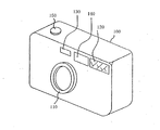
以下、本発明の実施例について、図面を参照して詳細に説明する。 本発明の実施例であるカメラについて図面を参照して説明する。ここで、図1は、本実施例のカメラの斜視図である。
Hereinafter, embodiments of the present invention will be described in detail with reference to the drawings. A camera according to an embodiment of the present invention will be described with reference to the drawings. Here, FIG. 1 is a perspective view of the camera of the present embodiment.
図1において、100はカメラ本体であり、このカメラ本体100の前面中央にはズーミングが可能なレンズ鏡筒110が設けられている。レンズ鏡筒110には、被写体にて反射された反射光の光通過光量を調節する光量調節装置が組み込まれている。光量調節装置の詳細な説明は、後述する。また、カメラ本体100の前面における向かって右側には被写体に照明光を照射するストロボ装置を構成する発光窓部120が設けられ、発光窓部120の左側にはファインダ窓140及び測光窓130がそれぞれ設けられている。
In FIG. 1,
さらに、カメラ本体100の上面には、撮影準備動作(焦点調節動作及び測光動作)及び撮影動作(フィルムやCCD、CMOSセンサ等の撮像素子への露光)を開始させるためのレリーズボタン150が設けられている。
Further, a
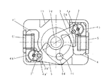
次に、図2を参照して、光量調節装置の構成について説明する。ここで、図2は、光量調節装置の分解斜視図である。 Next, the configuration of the light quantity adjusting device will be described with reference to FIG. Here, FIG. 2 is an exploded perspective view of the light amount adjusting device.
1は基板(ベース部材)であり、この基板1には以下に説明する部材が取り付けられている。基板1の中央には、被写体からの反射光を通過させる開口部1dが形成されている。また、基板1の略4隅には、第1及び第2の回転軸1a、1a’、第1及び第2のビス穴部1e、1e’が形成されており、第1及び第2の回転軸1a、1a’は、光軸を中心とした略点対称の配置関係を有しており、第1及び第2のビス穴部1e、1e’も光軸を中心とした略点対称の配置関係を有している。
7は光透過口7dを有した口径板(薄板部材)であり、開口部1dを覆うようにして基板1上に配されている。
2は永久磁石で構成された第1のロータマグネットであり、外周面が2極(N極、S極)に着磁されている。第1のロータマグネット2の軸受け穴部2aは、基板1に設けられた第1の回転軸1aに回転可能に支持されている。ロータマグネット2の上面には、凸状の駆動ピン2bが設けられている。なお、2’は、第2のロータマグネットであり、第1のロータマグネット2と同様の構成となっている。
3はシャッタ羽根(第1の遮光部材)であり、このシャッタ羽根3に形成された回転軸穴部3a及び長穴部3bはそれぞれ、第1の回転軸1a及び羽根駆動ピン2bに係合している。
4は軟磁性材料からなる板状の部材を一枚又は複数枚積層して構成した第1のステータヨークであり、この第1のステータヨーク4には、第1のロータマグネット2の外周曲面を挟んで対向する磁極部4a、4bが設けられている。また、第1のステータヨーク4は、後述する第1のコイル5とともに、基板1に対して図2中上側から取り付けられる。
5は第1のコイルであり、ボビン5aに導線を巻き回した構成となっている。この第1のコイル5は、第1のステータヨーク4が挿入された状態で、基板1に形成された光軸側に退避した第1の凹形状部1fに配置される。
第1の凹形状部1fを設けることにより、第1のコイル5を、最大で基板1の厚み分だけ、基板1の下面よりに配置できるため、光量調節装置12を光軸方向に小型化することができる。
第1のコイル5の第1のステータヨーク4挿入方向の両端面には、不図示の電源に接続された端子5d、5eを保持する端子保持部5a、5bが設けられている。
By providing the first concave-
Terminal holding
6は絞り羽根(第2の遮光部材)であり、この絞り羽根6に形成された回転軸穴部6a及び長穴部6bはそれぞれ、第2の回転軸1a’及び羽根駆動ピン2b’に係合している。
4’は軟磁性材料からなる板状の部材を一枚又は複数枚積層して構成した第2のステータヨークであり、この第2のステータヨーク4’には、第2のロータマグネット2’の外周曲面を挟んで対向する磁極部4a’、4b’が設けられている。また、この第2のテータヨーク4’は、後述する第2のコイル5’とともに、基板1に対して図2中上側から取り付けられる。
5’は第2のコイルであり、ボビン5a’に導線を巻き回した構成となっている。この第2のコイル5’は、第2のステータヨーク4’が挿入された状態で、基板1に形成された光軸側に退避した第2の凹形状部1f’に配置される。
Reference numeral 5 'denotes a second coil having a configuration in which a conducting wire is wound around a
第2の凹形状部1f’を設けることにより、第1の凹形状部1fと同様に、光量調節装置を光軸方向に小型化することができる。
By providing the second
第2のコイル5’における第2のステータヨーク4’挿入方向の両端面には、不図示の電源に接続された端子5d’、5e’を保持する端子保持部5b’、5c’が設けられている。
ここで、第1及び第2のロータマグネット2、2’、第1及び第2のステータヨーク4、4’、第1及び第2のコイル5、5’はそれぞれ同一形状であり、基板1に対して光軸Xを中心に略点対称の関係に配置される。
Here, the first and
8は羽根押さえ板(押さえ部材)であり、この羽根押さえ板8には、第1及び第2のビス9、9’を締結するための第1及び第2の貫通穴部8d、8d’が、第1及び第2のビス穴部1e、1e’に対応した位置、すなわち光軸に対して略点対称な配置関係を有するように形成されている。また、羽根押さえ板8のうち、第1及び第2の回転軸1a、1a’に対応した位置、すなわち光軸に対して略点対称な関係を有する位置には、第1及び第2の回転軸1a、1a’が係合する第1及び第2の軸穴部8e、8e’が設けられている。
ここで、羽根押さえ板8において、第1及び第2の貫通穴部8d、8d’の近傍部分は、他の部分よりも羽根押さえ板8の略厚み寸法t1だけ、下方に位置している。これにより、シャッタ羽根3および絞り羽根6の走行スペースを確実に確保することができる。
Here, in the
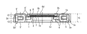
次に、図2、図3を参照して、光量調節装置12の光軸方向の厚みについて説明する。ここで、図3は、図2の矢印Y方向視における、光量調節装置の断面図である。 Next, the thickness of the light quantity adjusting device 12 in the optical axis direction will be described with reference to FIGS. Here, FIG. 3 is a cross-sectional view of the light amount adjusting device as viewed in the direction of arrow Y in FIG.
光量調節装置12の組み立て時において、羽根押さえ板8における、角部80b、81bの下面には、端子保持部5b、5cの上面(第1の当接面)50b、50cが当接する。この上面50b、50cは、第1のコイル5の上面(第1の面)よりも寸法t2だけ、下方に位置している。ここで、寸法t2は、羽根押さえ板8の厚み寸法t1と略同一に設定されている。
第1のコイル5および第1のステータヨーク4は、羽根押さえ板8および基板1により挟み込まれた状態で固定されている。
When the light amount adjusting device 12 is assembled, the upper surfaces (first contact surfaces) 50b and 50c of the
The
羽根押さえ板8における、角部80b’、81b’の下面には、端子保持部5b’、5c’の上面50b’、50c’が当接する。この上面50b’、50c’は、第2のコイル5’の上面(第1の面)よりも羽根押さえ板8の厚み寸法t2だけ、下方に位置している。第2のコイル5’および第2のステータヨーク4’は、羽根押さえ板8および基板1により挟み込まれた状態で固定されている。
The
上述の構成では、寸法t1と、羽根押さえ板8の厚み寸法t2とが略一致しているため、第1及び第2のコイル5、5’の上面及び端子保持部5b〜5c’の上面50b〜50c’を略同一平面内に配置することができる。
In the above-described configuration, since the dimension t1 and the thickness dimension t2 of the
また、端子保持部5b〜5c’の下面(第2の当接面)51b〜51c’は、第1及び第2のコイル5、5’の下面に対して寸法t3だけ上方に位置している。ここで、寸法t3は、基板1における第1及び第2の凹形状部1f、1f’の厚み寸法t4と略同一に設定されている。
Further, the lower surfaces (second contact surfaces) 51b to 51c ′ of the
これにより、光量調節装置12を組み立てた状態において、基板1の下面およびコイル5、5’の下面が略同一平面内に位置するようにすることができる。なお、端子5d〜5e’は、基板1の下面より下側に突出している。
Thereby, in a state where the light amount adjusting device 12 is assembled, the lower surface of the
図3に示すように、本実施例では第1及び第2のコイル5、5’を、羽根押さえ板8の上面から基板1の下面までの寸法t5内に配置することができるため、シャッタ駆動ユニット及び絞り駆動ユニットを別部材で支持していた従来例よりも、光量調節装置を光軸方向に小型化することができる。
すなわち、本実施例では、図3に示すように、第1及び第2のコイル5、5’を、光軸に対して点対称な位置に配置しているため、シャッタ羽根及び絞り羽根を駆動する2つの駆動ユニットを別部材で支持している従来例よりも、光量調節装置12を光軸方向に小型化することができる。
As shown in FIG. 3, in this embodiment, the first and
That is, in this embodiment, as shown in FIG. 3, the first and
また、本実施例では、シャッタ羽根3の駆動ユニット(第1のロータマグネット2,第1のステータヨーク4,第1のコイル5)及び絞り羽根6の駆動ユニット(第2のロータマグネット2’,第2のステータヨーク4’,第2のコイル5’)を単一の基板1で支持している。したがって、これらのコイルを別部材で支持する従来例よりも、部品点数を減らして、光量調節装置12の低コスト化を図ることができる。
In this embodiment, the drive unit for the shutter blade 3 (
また、第1及び第2のコイル5、5’(第1及び第2のステータヨーク4、4’)は、第1及び第2のビス9、9’を締結した際に、端子保持部5b〜5c’が羽根押さえ板8および基板1によって挟み込まれることにより固定されるため、コイル5、5’(ステータヨーク4、4’)を基板1に固定するために、別の部材(例えば、ビス)が不要になる。これにより、部品点数を削減できるため、光量調節装置12の低コスト化を図るとともに、光量調節装置12を小型化(薄型化)することができる。
The first and
次に、本実施形態における光量調節装置12の組み立て方法について説明する。 Next, a method for assembling the light amount adjusting device 12 in this embodiment will be described.
まず、第1のステータヨーク4が挿入された第1のコイル5を基板1に組み込む。同様に第2のステータヨーク4’が挿入された第2のコイル5’を基板1に組み込む。
First, the
次に、口径板7を固定するために、当接部7b、7b’を、第1及び第2のステータヨーク4、4’のうち光軸に面した領域の一部に係合させ、7a、7a’を基板1上に形成された凸部の突き当て面1a、1a’に係合させる。
Next, in order to fix the
そして、第1及び第2の回転軸1a、1a’に、第1及び第2のロータマグネット2、2’を挿入する。このとき、これらのロータマグネット2、2’は、無着磁状態である。次に、回転軸穴部3a及び長穴部3bを、第1の回転軸1a及び駆動ピン2bに係合させることにより、シャッタ羽根3を取り付ける。同様に、回転軸穴部6a及び長穴部6bを、第2の回転軸1a’及び駆動ピン2b’に係合させることにより、シャッタ羽根3を取り付ける。
Then, the first and
そして、第1及び第2のビス9、9’を、第1及び第2の貫通穴部8d、8d’を通して、第1及び第2のビス穴部1e、1e’にねじ込むことにより、羽根押さえ板8を基板1に固定する。最後にシャッタ羽根3および絞り羽根6を閉じ状態にして、第1及び第2のロータマグネット2、2’を同時に所定の磁化方向へ着磁する。これにより、光量調節装置12の組み立て作業が終了する。
Then, the first and
本実施例の光量調節装置12では、光量調節装置12を構成するすべての部品を基板1に対して一方(図2中上方)から取り付けることができるため、光量調節装置12の組み立てが容易になる。また、第1及び第2のロータマグネット2、2’を同時に着磁することで、工数の削減が図れる。
In the light amount adjusting device 12 of the present embodiment, since all the parts constituting the light amount adjusting device 12 can be attached to the
このように、シャッタ羽根3及び絞り羽根6を駆動する2つの駆動ユニットを、光軸に対して点対称な関係を有するように配置することで、これらの駆動ユニットを基板1及び羽根押さえ板8で挟みこんで支持した後に、第1及び第2のロータマグネット2、2’を同時に同一方向で着磁することが可能であり、微細な部品を使用していながら、従来の駆動ユニットよりも組み立てを容易にしている。
Thus, by arranging the two drive units that drive the
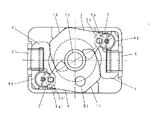
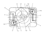
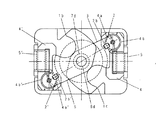
次に、上述した構成の光量調節装置12の動作について、図4〜図7を用いて説明する。ここで、図4〜図7では、羽根押さえ板8を取り外した状態で光量調節装置を図示している。
Next, the operation of the light amount adjusting device 12 having the above-described configuration will be described with reference to FIGS. Here, in FIG. 4 to FIG. 7, the light amount adjusting device is illustrated with the
図4は、シャッタ羽根3及び絞り羽根6が開状態にあるときの光量調節装置の状態を示している。また、図5は、シャッタ羽根が閉じ状態にあって、絞り羽根が開状態(開放口径でのシャッタ閉じ状態)にあるときの光量調節装置の状態を示している。図6は、シャッタ羽根が開状態にあって、絞り羽根の小絞り口径6dが光通過口内に進入した状態(小絞り開放状態)を示している。図7は、シャッタ羽根及び絞り羽根が光透過口内に進入した状態(小絞り口径でのシャッタ閉じ状態)を示している。
FIG. 4 shows a state of the light amount adjusting device when the
第1及び第2のコイル5、5’が通電OFF状態にあるとき、第1及び第2のステータヨーク4、4’は、非励磁状態にあり、シャッタ羽根3及び絞り羽根6は、第1及び第2のステータヨーク4、4’の磁極部4a〜4b’の吸引力(ディテントトルク)によって、当接部1b、1cに当接している。
When the first and
この状態から、第1のステータヨーク4の磁極部4aがS極になり、磁極部4bがN極になるように第1のコイル5の通電制御を行うと、第1のステータヨーク4と第1のロータマグネット2との間に吸引力と反発力が生じて、第1のロータマグネット2は、図4の状態から、反時計回り方向に約40°〜50°の角度で回転する。その結果、図5に示すように、シャッタ羽根3は、当接部1bから離脱し、光通過口7dを閉じる位置まで移動する。
From this state, when energization control of the
ここで、第1のロータマグネット2および第1のステータヨーク4は、第1のロータマグネット2の全作動範囲(角度40°〜50°)のうち中間位置(約20°〜25°)でディテントトルクがゼロとなり、かつディテントトルクの方向が該中間位置の前後で左右(逆方向)に切り換わるように配置されている。
Here, the
このような配置関係とすることにより、コイル5に通電してシャッタ羽根3の回動を行った後、通電OFFの状態にしても、ディテントトルクにより、シャッタ羽根3を、ストッパ部1bに当接した状態(光通過口7dを覆った状態)で保持することができる。
With this arrangement, the
次に、第1のステータヨーク4の磁極部4aがN極になり、磁極部4bがS極になるように第1のコイル5の通電制御を行うと、第1のステータヨーク4および第1のロータマグネット2の間に反発力と吸引力が生じて、第1のロータマグネット2が、図4中時計回り方向に約40°〜50°の角度だけ回転して、初期位置(図4に示す位置)に戻る。
Next, when energization control of the
図4の状態から、第2のステータヨーク4’の磁極部4a’がN極になり、磁極部4b’がS極になるように、第2のコイル5’を通電制御すると、第2のステータヨーク4’と第2のロータマグネット2’との間に吸引力と反発力が生じて第2のロータマグネット2’は、図4の状態から反時計回りに約40°〜50°の角度だけ回転する。
When the
これにより、絞り羽根6は、図6に示すように、開状態から閉じ状態(小絞り口径6dを光通過口7dに進入させた状態)まで移動する。
Thereby, as shown in FIG. 6, the
そして、第2のコイル5’を通電OFF状態にすると、第2のロータマグネット2’と第2のステータヨーク4’との間のディテントトルクによって絞り羽根6が、図6に示す状態に保持される。
When the
ここで、第1のステータヨーク4の磁極部4aがS極になり、磁極部4bがN極になるように第1のコイル5を通電制御すると、第1のステータヨーク4と第1のロータマグネット2との間に吸引力と反発力が生じて第1のロータマグネット2は、図6の状態から反時計回り方向に約40°〜50°の角度だけ回転する。
Here, when the
これにより、シャッタ羽根3は、開状態から光通過口7dを覆う位置まで移動する(図7参照)。
Thereby, the
このように第1及び第2のコイル5、5’への正、逆通電による第1及び第2のロータマグネット2、2’と、第1及び第2のステータヨーク4、4’の磁気的な吸引、反発作用によって、シャッタ羽根3及び絞り羽根6は、回転軸1a、1a’周りに回転して、光通過口7dを通過する光通過光量を調節する。
As described above, the first and
また、第1及び第2のコイル5、5’への通電が遮断された後は、第1及び第2のロータマグネット2、2’、第1及び第2のステータヨーク4、4’間に生じるディテントトルクにより、シャッタ羽根3および絞り羽根6は、当接部1b及び1cに当接した状態で停止する。
In addition, after the energization of the first and
なお、本実施例の光量調節装置12を、撮像媒体13がCCD等の撮像素子で構成されたデジタルカメラに搭載した場合には、第1及び第2のコイル5、5’への正、逆通電の制御により、シャッタ羽根3および絞り羽根6の駆動を制御することができる。また、本実施例の光量調節装置12を、撮像媒体13がフィルムで構成されたカメラに搭載する場合には、第1及び第2のコイル5、5’への通電時間および通電タイミングにより、シャッタ羽根3および絞り羽根6の駆動を制御することになる。
In addition, when the light quantity adjusting device 12 of the present embodiment is mounted on a digital camera in which the imaging medium 13 is configured by an imaging element such as a CCD, the forward and reverse directions to the first and
本実施例の光量調節装置は、カメラ本体に着脱可能なレンズ装置(光学機器)やカメラが内蔵された携帯電子機器(携帯電話、光学機器)等にも搭載することができる。 The light amount adjusting device of this embodiment can be mounted on a lens device (optical device) that can be attached to and detached from the camera body, a portable electronic device (mobile phone, optical device) in which the camera is built, and the like.
以上、本発明の光量調節装置によれば、装置全体を小型化できるとともに、コイルユニットに供給する電力を大きくしなくても遮光部材を効率良く駆動することができる。 As described above, according to the light amount adjusting apparatus of the present invention, the entire apparatus can be reduced in size, and the light shielding member can be efficiently driven without increasing the power supplied to the coil unit.
1 基板
1b、1c 突き当て面
2 ロータマグネット
2b、2b’ 駆動ピン
3 シャッタ羽根
3a 回転軸穴部
3b 長穴部
4、4’ ステータヨーク
5、5’ コイル
5b、5c
6 絞り羽根
6a 回転軸穴部
6b 長穴部
7 口径板
8 羽根押さえ板
DESCRIPTION OF
6
Claims (8)
該ベース部材に対して移動可能な第1及び第2の遮光部材と、
前記ベース部材の一方の面との間に、前記第1及び第2の遮光部材を挟み込むように配置された押さえ部材と、
第1のコイルに通電して第1のロータマグネットを回転させることにより、前記第1の遮光部材を駆動する第1の駆動ユニットと、
第2のコイルに通電して第2のロータマグネットを回転させることにより、前記第2の遮光部材を駆動する第2の駆動ユニットとを有し、
前記第1及び第2のコイルは、前記ベース部材の他方の面と、前記押さえ部材の前記ベース部材とは反対側の面との寸法の範囲内に配置されることを特徴とする光量調節装置。 A base member having a light passage opening formed thereon;
First and second light shielding members movable relative to the base member;
A pressing member disposed so as to sandwich the first and second light shielding members between one surface of the base member;
A first drive unit for driving the first light shielding member by energizing the first coil and rotating the first rotor magnet;
A second drive unit that drives the second light-shielding member by energizing the second coil and rotating the second rotor magnet;
The first and second coils are disposed within a size range of the other surface of the base member and the surface of the pressing member opposite to the base member. .
前記第1及び第2の支持軸は、光軸に対して略点対称な配置関係を有することを特徴とする請求項2に記載の光量調節装置。 The base member supports a first support shaft that rotatably supports the first rotor magnet and the first light shielding member, and rotatably supports the second rotor magnet and the second light shielding member. A second support shaft is provided,
The light amount adjusting device according to claim 2, wherein the first and second support shafts have a substantially point-symmetric arrangement relationship with respect to the optical axis.
前記第1及び第2の締結部材は、光軸に対して略点対称な配置関係を有することを特徴とする請求項2又は3に記載の光量調節装置。 Having first and second fastening members for fastening the pressing member and the base member;
The light quantity adjusting device according to claim 2, wherein the first and second fastening members have a substantially point-symmetric arrangement relationship with respect to the optical axis.
前記押さえ部材及び前記ベース部材にそれぞれ当接する第1及び第2の当接面を有して、端子を保持する端子保持部材とを有しており、
前記第1の当接面は、前記第1の面よりも前記押さえ部材の略厚み分だけ、前記ベース部材側に配置されており、前記第2の当接面は、前記第2の面よりも前記ベース部材の略厚み分だけ、前記押さえ部材側に配置されていることを特徴とする請求項5に記載の光量調節装置。 In the optical axis direction, the first and second coils are respectively arranged in order from the pressing member side, first and second surfaces;
A first holding surface and a second holding surface for contacting the pressing member and the base member, respectively, and a terminal holding member for holding the terminal,
The first contact surface is disposed closer to the base member than the first surface by approximately the thickness of the pressing member, and the second contact surface is formed from the second surface. The light amount adjusting device according to claim 5, wherein the light amount adjusting device is disposed on the side of the pressing member by an amount substantially equal to the thickness of the base member.
Priority Applications (1)
| Application Number | Priority Date | Filing Date | Title |
|---|---|---|---|
| JP2004105501A JP4423089B2 (en) | 2004-03-31 | 2004-03-31 | Light amount adjusting device and optical apparatus |
Applications Claiming Priority (1)
| Application Number | Priority Date | Filing Date | Title |
|---|---|---|---|
| JP2004105501A JP4423089B2 (en) | 2004-03-31 | 2004-03-31 | Light amount adjusting device and optical apparatus |
Publications (3)
| Publication Number | Publication Date |
|---|---|
| JP2005292355A true JP2005292355A (en) | 2005-10-20 |
| JP2005292355A5 JP2005292355A5 (en) | 2007-05-24 |
| JP4423089B2 JP4423089B2 (en) | 2010-03-03 |
Family
ID=35325366
Family Applications (1)
| Application Number | Title | Priority Date | Filing Date |
|---|---|---|---|
| JP2004105501A Expired - Lifetime JP4423089B2 (en) | 2004-03-31 | 2004-03-31 | Light amount adjusting device and optical apparatus |
Country Status (1)
| Country | Link |
|---|---|
| JP (1) | JP4423089B2 (en) |
Cited By (6)
| Publication number | Priority date | Publication date | Assignee | Title |
|---|---|---|---|---|
| JP2006011293A (en) * | 2004-06-29 | 2006-01-12 | Nidec Copal Corp | Camera blade driving apparatus |
| WO2007055085A1 (en) * | 2005-11-11 | 2007-05-18 | Konica Minolta Opto, Inc. | Lens unit |
| JP2008026525A (en) * | 2006-07-20 | 2008-02-07 | Canon Electronics Inc | Light quantity adjusting device and optical equipment |
| EP1984999A2 (en) * | 2006-01-26 | 2008-10-29 | Melles Griot, Inc. | Rotor magnet driven optical shutter assembly |
| CN106933003A (en) * | 2015-12-30 | 2017-07-07 | 亚洲光学股份有限公司 | Aperture-adjustable lens device |
| US10523850B2 (en) | 2015-12-30 | 2019-12-31 | Sintai Optical (Shenzhen) Co., Ltd. | Camera device with adjustable aperture |
-
2004
- 2004-03-31 JP JP2004105501A patent/JP4423089B2/en not_active Expired - Lifetime
Cited By (11)
| Publication number | Priority date | Publication date | Assignee | Title |
|---|---|---|---|---|
| JP2006011293A (en) * | 2004-06-29 | 2006-01-12 | Nidec Copal Corp | Camera blade driving apparatus |
| JP4549115B2 (en) * | 2004-06-29 | 2010-09-22 | 日本電産コパル株式会社 | Camera blade drive |
| WO2007055085A1 (en) * | 2005-11-11 | 2007-05-18 | Konica Minolta Opto, Inc. | Lens unit |
| US7636211B2 (en) | 2005-11-11 | 2009-12-22 | Konica Minolta Opto, Inc. | Lens unit |
| JP4992112B2 (en) * | 2005-11-11 | 2012-08-08 | コニカミノルタアドバンストレイヤー株式会社 | Lens unit |
| EP1984999A2 (en) * | 2006-01-26 | 2008-10-29 | Melles Griot, Inc. | Rotor magnet driven optical shutter assembly |
| EP1984999A4 (en) * | 2006-01-26 | 2010-02-24 | Melles Griot Inc | Rotor magnet driven optical shutter assembly |
| JP2008026525A (en) * | 2006-07-20 | 2008-02-07 | Canon Electronics Inc | Light quantity adjusting device and optical equipment |
| CN106933003A (en) * | 2015-12-30 | 2017-07-07 | 亚洲光学股份有限公司 | Aperture-adjustable lens device |
| JP2018109741A (en) * | 2015-12-30 | 2018-07-12 | 信泰光学(深▲せん▼)有限公司Sintai Optical (Shenzhen) Co., Ltd. | Diaphragm adjustable lens device |
| US10523850B2 (en) | 2015-12-30 | 2019-12-31 | Sintai Optical (Shenzhen) Co., Ltd. | Camera device with adjustable aperture |
Also Published As
| Publication number | Publication date |
|---|---|
| JP4423089B2 (en) | 2010-03-03 |
Similar Documents
| Publication | Publication Date | Title |
|---|---|---|
| JP4549115B2 (en) | Camera blade drive | |
| JP2007189824A (en) | Magnet rotor, electromagnetic drive device therewith, and optical instrument having optical amount adjusting device | |
| JPWO2004107036A1 (en) | Aperture device | |
| JP2005221770A (en) | Lens barrel and image pickup device equipped with the same | |
| JP2008176062A (en) | Light quantity adjusting device and imaging apparatus | |
| US20100329664A1 (en) | Shutter device for camera | |
| JP4423089B2 (en) | Light amount adjusting device and optical apparatus | |
| JP4522691B2 (en) | Camera blade drive | |
| JP4204311B2 (en) | Light control device | |
| JP2007079390A (en) | Lens driving device | |
| JP2008040114A (en) | Shutter device and imaging apparatus using the same | |
| JP4954553B2 (en) | Light amount adjusting device and camera | |
| JP5183898B2 (en) | Electromagnetic actuator and camera blade drive device using the same | |
| JP2004258062A (en) | Shutter driving device used also as diaphragm | |
| JP4549196B2 (en) | Camera blade drive | |
| JP2005241874A (en) | Blade driving device for camera | |
| JP5047460B2 (en) | Imaging optical unit and imaging apparatus | |
| JP2007093912A (en) | Blade driving device for camera | |
| JP2019148699A (en) | Blade driving unit and imaging module | |
| JP5047459B2 (en) | Light amount adjusting device, imaging optical unit, and imaging device | |
| JP4334337B2 (en) | Camera blade drive | |
| JP2004191750A (en) | Light amount control device | |
| JP7038003B2 (en) | Blade drive | |
| JP2003309940A (en) | Electromagnetic drive apparatus, and light quantity adjusting apparatus | |
| JP4238127B2 (en) | Camera blade drive |
Legal Events
| Date | Code | Title | Description |
|---|---|---|---|
| A521 | Request for written amendment filed |
Free format text: JAPANESE INTERMEDIATE CODE: A523 Effective date: 20070330 |
|
| A621 | Written request for application examination |
Free format text: JAPANESE INTERMEDIATE CODE: A621 Effective date: 20070330 |
|
| RD03 | Notification of appointment of power of attorney |
Free format text: JAPANESE INTERMEDIATE CODE: A7423 Effective date: 20081125 |
|
| RD04 | Notification of resignation of power of attorney |
Free format text: JAPANESE INTERMEDIATE CODE: A7424 Effective date: 20081211 |
|
| A977 | Report on retrieval |
Free format text: JAPANESE INTERMEDIATE CODE: A971007 Effective date: 20090806 |
|
| A131 | Notification of reasons for refusal |
Free format text: JAPANESE INTERMEDIATE CODE: A131 Effective date: 20090811 |
|
| A521 | Request for written amendment filed |
Free format text: JAPANESE INTERMEDIATE CODE: A523 Effective date: 20091009 |
|
| A521 | Request for written amendment filed |
Free format text: JAPANESE INTERMEDIATE CODE: A523 Effective date: 20091019 |
|
| TRDD | Decision of grant or rejection written | ||
| A01 | Written decision to grant a patent or to grant a registration (utility model) |
Free format text: JAPANESE INTERMEDIATE CODE: A01 Effective date: 20091110 |
|
| A01 | Written decision to grant a patent or to grant a registration (utility model) |
Free format text: JAPANESE INTERMEDIATE CODE: A01 |
|
| A61 | First payment of annual fees (during grant procedure) |
Free format text: JAPANESE INTERMEDIATE CODE: A61 Effective date: 20091207 |
|
| FPAY | Renewal fee payment (event date is renewal date of database) |
Free format text: PAYMENT UNTIL: 20121211 Year of fee payment: 3 |
|
| R150 | Certificate of patent or registration of utility model |
Ref document number: 4423089 Country of ref document: JP Free format text: JAPANESE INTERMEDIATE CODE: R150 Free format text: JAPANESE INTERMEDIATE CODE: R150 |
|
| FPAY | Renewal fee payment (event date is renewal date of database) |
Free format text: PAYMENT UNTIL: 20121211 Year of fee payment: 3 |
|
| FPAY | Renewal fee payment (event date is renewal date of database) |
Free format text: PAYMENT UNTIL: 20131211 Year of fee payment: 4 |
|
| R250 | Receipt of annual fees |
Free format text: JAPANESE INTERMEDIATE CODE: R250 |
|
| R250 | Receipt of annual fees |
Free format text: JAPANESE INTERMEDIATE CODE: R250 |
|
| R250 | Receipt of annual fees |
Free format text: JAPANESE INTERMEDIATE CODE: R250 |
|
| R250 | Receipt of annual fees |
Free format text: JAPANESE INTERMEDIATE CODE: R250 |
|
| R250 | Receipt of annual fees |
Free format text: JAPANESE INTERMEDIATE CODE: R250 |
|
| R250 | Receipt of annual fees |
Free format text: JAPANESE INTERMEDIATE CODE: R250 |
|
| R250 | Receipt of annual fees |
Free format text: JAPANESE INTERMEDIATE CODE: R250 |
|
| R250 | Receipt of annual fees |
Free format text: JAPANESE INTERMEDIATE CODE: R250 |