JP2008040114A - Shutter device and imaging apparatus using the same - Google Patents
Shutter device and imaging apparatus using the same Download PDFInfo
- Publication number
- JP2008040114A JP2008040114A JP2006213791A JP2006213791A JP2008040114A JP 2008040114 A JP2008040114 A JP 2008040114A JP 2006213791 A JP2006213791 A JP 2006213791A JP 2006213791 A JP2006213791 A JP 2006213791A JP 2008040114 A JP2008040114 A JP 2008040114A
- Authority
- JP
- Japan
- Prior art keywords
- yoke
- rotor
- shutter device
- substrate
- opening
- Prior art date
- Legal status (The legal status is an assumption and is not a legal conclusion. Google has not performed a legal analysis and makes no representation as to the accuracy of the status listed.)
- Pending
Links
Images


Abstract
Description
この発明は、デジタルカメラなどの撮像装置に備えられるシャッタ装置およびこれを用いた撮像装置に関する。 The present invention relates to a shutter device provided in an imaging apparatus such as a digital camera and an imaging apparatus using the same.
従来より、カメラ付携帯電話やデジタルカメラなどの撮像装置に搭載されるカメラモジュールの中には、セクタ(シャッタの羽根)を開閉させることによって、CCDなどの受光素子に導入される光量を調整する機械式のシャッタ装置を備えたものがある。そして、このようなシャッタ装置においては、ヨークの途中に設けられたコイルに通電することよりヨークを励磁させ、これによって生じた磁力を利用してロータを回動させることによって、ロータと連結されたセクタを開閉させるアクチュエータが多く用いられている(例えば、下記特許文献1参照。)。 Conventionally, in a camera module mounted on an imaging device such as a camera-equipped mobile phone or a digital camera, the amount of light introduced into a light receiving element such as a CCD is adjusted by opening and closing a sector (shutter blade). Some have a mechanical shutter device. In such a shutter device, the yoke is excited by energizing a coil provided in the middle of the yoke, and is connected to the rotor by rotating the rotor using the magnetic force generated thereby. Many actuators that open and close the sector are used (for example, see Patent Document 1 below).
しかしながら、上記の従来技術では、ヨークの一端部と他端部との間にロータを収めることが可能な形状としたうえで、コイルを設けることが可能な略U字状のヨークが一般的に用いられている。そして、このような略U字状のヨークをシャッタ装置に用いた場合、光軸から離れた位置にヨークおよびコイルを配置するための十分なスペースを確保しなければならず、シャッタ装置を容易に小型化することができないといった問題が生じていた。 However, in the above-described conventional technology, a generally U-shaped yoke that can be provided with a coil after having a shape that can accommodate a rotor between one end and the other end of the yoke is generally used. It is used. When such a substantially U-shaped yoke is used in the shutter device, a sufficient space for arranging the yoke and the coil at a position away from the optical axis must be secured, and the shutter device can be easily formed. There has been a problem that it cannot be miniaturized.
特に、近年においては、カメラ付携帯電話やデジタルカメラなどの小型化に伴い、より小型なカメラモジュールが求められている中、シャッタ装置の小型化が、カメラモジュール開発において課題となっていた。 In particular, in recent years, along with the downsizing of camera-equipped mobile phones, digital cameras, and the like, there has been a demand for smaller camera modules, and downsizing of shutter devices has been a challenge in developing camera modules.
(従来技術によるシャッタ装置の構成)
ここで、上述した従来技術によるシャッタ装置の一例について説明する。図17および図18は、従来技術によるシャッタユニットの一例を示す説明図である。
(Configuration of shutter device according to prior art)
Here, an example of the above-described conventional shutter device will be described. 17 and 18 are explanatory views showing an example of a conventional shutter unit.
図17および図18に示すように、シャッタユニット1700は、基板1710を備え、当該基板1710の光軸1700A方向の物体側に形成された面1710Aにおいては、コイル1721と、コイル1721が通電されることによって励磁されるヨーク1722とからなる駆動手段1720が配設されている。
As shown in FIGS. 17 and 18, the
また、基板1710の面1710Aから、光軸1700A方向の反対側(像面側)の面へ向かって基板1710内部を貫通するようにロータ1730が回動自在に配設されている。このロータ1730の外周面は、2極の永久磁石によって着磁されている。そして、板状の閉塞板1740によって、ロータ1730が軸受けされつつ、コイル1721、ヨーク1722およびロータ1730が閉鎖される。
A
また、基板1710の内部には、ロータ1730の回動と連動して基板1710に形成された開口部1710Bを開閉するセクタ(図示省略)が配設されている。さらに、基板1710には、開口部1710Bよりも大きい内径を有し、図19および図20を用いて説明するレンズユニット1900が嵌合される凹状の空間部1710Cが形成されている。
In addition, a sector (not shown) that opens and closes an opening 1710 </ b> B formed in the
このように構成されたシャッタユニット1700は、コイル1721が通電され、ヨーク1722が励磁されることによって、ロータ1730において所定方向への磁力(吸引力)が生じる。これにより、ロータ1730は、所定方向に回動する。そして、ロータ1730の回動と連動するセクタによって開口部1710Bが開閉される。
In the
ここで、ヨーク1722は、図17に示すように、基板1710上に配置されたときに一端部と他端部の間にロータ1730を収めることが可能であり、かつ途中にコイル1721を設けることが可能であり、さらにシャッタユニット1700と図19および図20を用いて説明するレンズユニット1900とが組み立てられ、一体化されたときに、レンズユニット1900を構成するレンズ枠1910Dとの干渉を防止することが可能な略U字状の形状を有する。
Here, as shown in FIG. 17, when the
このように、シャッタユニット1700は、ヨーク1722およびコイル1721がレンズ枠1910Dと干渉しないように、基板1710上におけるレンズ枠1910Dから離れた位置にヨーク1722およびコイル1721を配置したうえで、可能な限り小型化され、このシャッタユニット1700の光軸1700Aと直交する方向における外形寸法(横幅寸法)はW3となっているが、上述したようなシャッタユニット1700の構成を用いる限り、シャッタユニット1700の光軸1700Aと直交する方向における外形寸法を容易に小型化することができないといった問題が生じていた。
As described above, in the
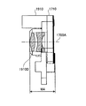
また、図19および図20は、従来技術によるレンズユニットの一例を示す説明図である。図19および図20において、レンズユニット1900は、上述したシャッタユニット1700と一体化されるものであり、基板1910を備え、当該基板1910の光軸1700A方向の物体側に形成された面1910Aには、円形かつ光軸1700Aと同軸の開口部1910Cが形成された円筒状のレンズ枠1910Dが、面1910Aから突出するように形成されている。このレンズ枠1910Dに形成された開口部1910Cの内部には、レンズ1921およびレンズ1922からなるレンズ群1920が配設される。
19 and 20 are explanatory views showing an example of a lens unit according to the prior art. 19 and 20, the
また、図21は、一体化された状態のシャッタユニット1700およびレンズユニット1900を示す説明図である。図17および図18を用いて説明したシャッタユニット1700、および図19および図20を用いて説明したレンズユニット1900は、それぞれが別工程において組み立てられる。そして、シャッタユニット1700の面1710Aと、レンズユニット1900の面1910Bとが当接しつつ、シャッタユニット1700に形成された空間部1710Cに、レンズユニット1900に設けられたレンズ1922の一部が収容されるように、シャッタユニット1700とレンズユニット1900とが組み立てられ、図21に示すように一体化される。
FIG. 21 is an explanatory diagram showing the
このように、従来技術によるシャッタ装置は、シャッタユニット1700と、レンズユニット1900とを一体化したうえで、可能な限り小型することが可能な構成となっており、このシャッタ装置の光軸1700A方向における外形寸法(厚さ寸法)はW4となっているが、上述したようなシャッタ装置の構成を用いる限り、シャッタ装置の光軸1700A方向における外形寸法を容易に小型化することができないといった問題が生じていた。
As described above, the shutter device according to the prior art is configured to be as small as possible after integrating the
この発明は、上述した従来技術による問題点を解消するため、より小型化されたシャッタ装置およびこれを用いた撮像装置を提供することを目的とする。 SUMMARY OF THE INVENTION An object of the present invention is to provide a more compact shutter device and an image pickup apparatus using the shutter device in order to solve the above-described problems caused by the prior art.
上述した課題を解決し、目的を達成するため、この発明にかかるシャッタ装置は、光軸を中心とする開口部が形成された基板と、コイルと、ヨークと、からなる駆動手段と、前記駆動手段の駆動により回動するロータと、前記ロータの回動により前記開口部を開閉するセクタ部と、を備え、前記ヨークは、前記開口部の外周形状に対応する係合可能な形状に形成されて配置されることを特徴とする。 In order to solve the above-described problems and achieve the object, a shutter device according to the present invention includes a drive unit including a substrate having an opening centered on an optical axis, a coil, and a yoke, and the drive. A rotor that rotates by driving of the means, and a sector that opens and closes the opening by rotation of the rotor, and the yoke is formed in an engageable shape corresponding to the outer peripheral shape of the opening. It is characterized by being arranged.
また、この発明にかかるシャッタ装置は、光軸を中心とする開口部が形成された基板と、コイルと、ヨークと、からなる駆動手段と、前記駆動手段の駆動により回動するロータと、前記ロータの回動により前記開口部を開閉するセクタ部と、を備え、前記ヨークは、前記開口部の外周部を取り囲むように略環状に形成されて配置されることを特徴とする。 According to another aspect of the present invention, there is provided a shutter device comprising: a substrate having an opening centered on an optical axis; a driving unit comprising a coil and a yoke; a rotor that is rotated by driving of the driving unit; And a sector part that opens and closes the opening by rotation of a rotor, and the yoke is formed and arranged in a substantially annular shape so as to surround an outer peripheral part of the opening.
また、この発明にかかるシャッタ装置は、レンズが配置される開口部が形成された基板と、コイルと、ヨークと、からなる駆動手段と、前記駆動手段の駆動により回動するロータと、前記ロータの回動により前記開口部を開閉するセクタ部と、を備え、前記ヨークは、前記開口部の外周部を取り囲むように略環状に形成されて配置されることを特徴とする。 According to another aspect of the present invention, there is provided a shutter device comprising: a substrate having an opening on which a lens is disposed; a driving means comprising a coil and a yoke; a rotor that is rotated by driving the driving means; and the rotor And a sector portion that opens and closes the opening by rotation of the opening, and the yoke is formed in a substantially annular shape so as to surround the outer periphery of the opening.
また、この発明にかかるシャッタ装置は、上記に記載の発明において、前記基板から突出し前記開口部が形成された枠部を備え、前記ヨークは、前記枠部の外周部を取り囲むように略環状に形成されて配置されることを特徴とする。 The shutter device according to the present invention includes a frame portion that protrudes from the substrate and has the opening formed therein, and the yoke is substantially annular so as to surround an outer peripheral portion of the frame portion. It is formed and arranged.
また、この発明にかかるシャッタ装置は、上記に記載の発明において、前記ヨークは、前記枠部の外周部に係合して位置決め固定されることを特徴とする。 The shutter device according to the present invention is characterized in that, in the above-described invention, the yoke is engaged and fixed to the outer peripheral portion of the frame portion.
また、この発明にかかるシャッタ装置は、上記に記載の発明において、前記基板には、前記ヨークを係止する嵌合部が形成されていることを特徴とする。 The shutter device according to the present invention is characterized in that, in the above-described invention, the substrate is formed with a fitting portion for locking the yoke.
また、この発明にかかるシャッタ装置は、上記に記載の発明において、前記枠部は、円環状に形成されており、前記ヨークは、円環状に形成された前記枠部の外周部に沿った略円環状に形成されていることを特徴とする。 Further, in the shutter device according to the present invention, in the invention described above, the frame portion is formed in an annular shape, and the yoke is substantially along an outer peripheral portion of the frame portion formed in an annular shape. It is characterized by being formed in an annular shape.
また、この発明にかかるシャッタ装置は、上記に記載の発明において、前記ヨークは、円環状に形成された前記枠部の外周部に沿った略円環状の部分と、前記コイルが設けられる直線状の部分とからなることを特徴とする。 Further, in the shutter device according to the present invention, in the invention described above, the yoke has a substantially annular portion along the outer peripheral portion of the frame portion formed in an annular shape, and a linear shape in which the coil is provided. It consists of these parts.
また、この発明にかかるシャッタ装置は、上記に記載の発明において、前記枠部は、前記基板と一体形成されていることを特徴とする。 The shutter device according to the present invention is characterized in that, in the above-described invention, the frame portion is integrally formed with the substrate.
また、この発明にかかるシャッタ装置は、上記に記載の発明において、前記基板には、前記ロータが収容されるロータ収容部と、前記ロータを軸受けする軸受部とが形成されていることを特徴とする。 The shutter device according to the present invention is characterized in that, in the above-described invention, the substrate is formed with a rotor accommodating portion for accommodating the rotor and a bearing portion for bearing the rotor. To do.
また、この発明にかかるシャッタ装置は、上記に記載の発明において、前記軸受部は、前記ヨークの一端部および他端部と、前記ロータの側面部との間隔を所定の間隔に保持する位置決め部を備えたことを特徴とする。 Further, in the shutter device according to the present invention, in the invention described above, the bearing portion is a positioning portion that maintains a predetermined distance between the one end portion and the other end portion of the yoke and the side surface portion of the rotor. It is provided with.
また、この発明にかかるシャッタ装置は、上記に記載の発明において、前記基板には、前記セクタ部が収容される空間部が形成されており、当該空間部を閉塞する板状の部材を備えたことを特徴とする。 In the shutter device according to the present invention, in the above-described invention, the substrate includes a space portion in which the sector portion is accommodated, and includes a plate-like member that closes the space portion. It is characterized by that.
また、この発明にかかるシャッタ装置は、上記に記載の発明において、前記コイルの長さ、個数、および配置位置は前記ヨークの形状に対応して設けられていることを特徴とする。 The shutter device according to the present invention is characterized in that, in the above-described invention, the length, the number, and the arrangement position of the coils are provided corresponding to the shape of the yoke.
また、この発明にかかる撮像装置は、上記に記載のシャッタ装置を備えたことを特徴とする。 According to another aspect of the present invention, there is provided an image pickup apparatus including the shutter device described above.
本発明によれば、より小型化されたシャッタ装置およびこれを用いた撮像装置を提供することができるという効果を奏する。 According to the present invention, it is possible to provide a more compact shutter device and an imaging device using the shutter device.
以下に添付図面を参照して、この発明にかかるシャッタ装置およびこれを用いた撮像装置の好適な実施の形態を詳細に説明する。 Exemplary embodiments of a shutter device and an imaging device using the same according to the present invention will be explained below in detail with reference to the accompanying drawings.
(実施の形態1)
(シャッタユニットの構成)
まず、実施の形態1について説明する。実施の形態1は、この発明にかかるシャッタ装置を用いた携帯電話の構成例である。まず、この発明にかかるシャッタ装置を備えたシャッタユニット112の構成について説明する。図1は、この発明にかかるシャッタ装置を備えたシャッタユニット112の部品構成を示す説明図である。また、図2、図3および図4は、この発明にかかるシャッタ装置を備えたシャッタユニット112の外観を示す斜視図である。
(Embodiment 1)
(Configuration of shutter unit)
First, the first embodiment will be described. The first embodiment is a configuration example of a mobile phone using the shutter device according to the present invention. First, the configuration of the
図1は、シャッタユニット112の部品構成を示したものである。図1に示すように、レンズ枠300Cの内部には、光軸110A方向の物体側から順に第2レンズ群600(レンズ600A、レンズスペーサ600B、レンズ600C)が配設され、最後にレンズ押え環600Dによって位置決め固定される。これにより第2レンズ群600は、レンズ押え環600Dによってレンズ枠300Cの内部に形成された当接面に対して押さえつけられるようにして支持される。
FIG. 1 shows a component configuration of the
また、図1に示されるように、シャッタユニット112の組み立て時には、まず、光軸110Aの物体側から駆動手段310がレンズ枠300Cに挿嵌され、当該レンズ枠300C、および軸受部300Bに備えられた位置決め部300Sによって位置決め固定され、係止ツメ300D(図2参照)によって係止される。
As shown in FIG. 1, when the
そして、光軸110Aの像面側から、第2レンズ群600がレンズ枠300Cの内部に挿嵌され、上述したようにレンズ押え環600Dによって押さえつけられるようにして支持される。さらに、光軸110Aの像面側から、ロータ320がロータ収容部300Jに挿入され、軸受部300Bによって軸受けされる。
Then, from the image plane side of the
さらに、セクタ部500がロータ320と係合するように空間部300G(図4参照)に配置される。最後に、裏板400が、空間部300Gを閉塞するように、螺子401によって螺着されることによって、ロータ320およびセクタ部500が支持される。
Further, the
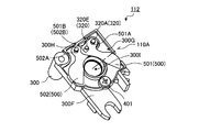
図2は、シャッタユニット112の光軸110A方向の物体側を示したものである。図2に示すように、シャッタユニット112は、基板300を備え、当該基板300の光軸110A方向の物体側に形成された面300Aにおいては、ヨーク312と、ヨーク312の途中に設けられ、通電されることによってヨーク312を励磁するコイル311とからなる駆動手段310が配設されている。
FIG. 2 shows the object side of the
また、基板300における、ヨーク312の一端部と他端部との間には、基板300の面300Aから、光軸110A方向の反対側(像面側)の面300F(図3参照)へ向かって貫通するようにロータ320が収容されるロータ収容部300J(図1参照)が形成されている。そして、ロータ収容部300Jに収容されたロータ320は、基板300から突出するように形成された軸受部300Bによって軸320Aが軸受けされ、光軸110A方向への移動が係止される。
Further, between the one end and the other end of the
ここで軸受部300Bは、その柱部において、ヨーク312の一端部と他端部との間に挟まれるように、ヨーク312の一端部と他端部とを位置決め固定し、ヨーク312の一端部および他端部と、ロータ320の側面部との間隔を所定の間隔に保持する所定の幅を有する位置決め部300S(図1参照)を備える。
Here, the bearing
また、基板300には、円形かつ光軸110Aと同軸の開口部300Eが形成された円筒状のレンズ枠(枠部)300Cが、基板300の面300Aから突出するように形成されている。このレンズ枠300Cに形成された開口部300Eの内部には、第2レンズ群600(図1参照)が配設される。
The
ここで、ヨーク312は、図2に示すように、円環状に形成されたレンズ枠300Cのレンズ枠300Cの外周形状に対応する係合可能な形状に形成されている。また、ヨーク312は、レンズ枠300Cの外周部に沿った略円環状(略環状)の円環部312Aと、コイル311が設けられる直線状の直線部312Sとからなる。また、ヨーク312は、レンズ枠300Cの外周面を取り囲むように基板300上に配置される。そして、ヨーク312は、レンズ枠300Cの外周面に嵌合して位置決め固定される。
Here, as shown in FIG. 2, the
また、ヨーク312の円環部312Aは、その内周面においてレンズ枠300Cの外周面に当接しつつ軽圧入可能な内径寸法を有する。これにより、レンズ枠300Cに対してヨーク312を軽圧入することで、コイル311およびヨーク312を容易かつ確実に位置決め固定することが可能となっている。ここで、ヨーク312は、略円環状に限らず、たとえばレンズ枠300Cが円環状に形成されていない場合であっても、レンズ枠300Cを取り囲むようにレンズ枠300Cの外周部に沿った形状であって、かつレンズ枠300Cの外周形状に対応する係合可能な形状であればよい。
In addition, the
なお、本実施の形態におけるシャッタユニット112は、図2に示すように、基板300上の複数箇所に形成された係止ツメ(嵌合部)300Dによって、レンズ枠300Cの外周面に嵌合して位置決め固定されたヨーク312を係止する構成を用いている。これにより、コイル311およびヨーク312をより容易かつ確実に位置決め固定することが可能となっているだけでなく、コイル311およびヨーク312の容易な着脱を可能としている。
As shown in FIG. 2, the
また、図3は、シャッタユニット112の光軸110A方向の像面側を示したものである。図3に示すように、基板300の面300Fには、レンズ枠300Cに形成された開口部300E(図2参照)とつながる円形かつ光軸110Aと同軸の開口部300Iが形成されている。
FIG. 3 shows the image plane side of the
また、基板300の面300Fにおいては、セクタ部500が収容される凹状の空間部300G(図4参照)が形成されており、当該空間部300Gは、板状の部材からなる裏板400によって閉塞される。この裏板400は、螺子401によって、基板300に螺着される。また、裏板400にはロータ320に形成された軸320Aを軸支する開口部400Aが形成されている。
In addition, a
また、図4は、裏板400が脱された状態のシャッタユニット112の光軸110A方向の像面側を示したものである。図4に示すように、基板300の面300Fにおいては、空間部300Gが形成されている。そして、この空間部300Gには、基板300の面300A(図2参照)から面300Fに向かって貫設されたロータ320と係合し、当該ロータ320の回動に伴って開閉するセクタA501とセクタB502とからなるセクタ部500が配設されている。
FIG. 4 shows the image plane side in the direction of the
このうち、セクタA501は、当該セクタA501に形成された開口部501Aを貫通するロータ320に形成された軸320Aによって軸支される。また、セクタB502は、当該セクタB502に形成された開口部502Aを貫通する面300Fに形成された突起部300Hによって軸支される。またセクタA501には、図5を用いて説明する突起部320Eが貫通する長穴状の開口部501Bが形成されている。また、セクタB502には、同じく突起部320Eが貫通する長穴状の開口部502Bが形成されている。
Of these, the sector A501 is pivotally supported by a
(駆動手段310の構成)
つぎに、駆動手段310の構成について説明する。図5は、駆動手段310およびロータ320の外観を示す斜視図である。
(Configuration of driving means 310)
Next, the configuration of the
図5において、コイル311は、ボビン311Aと、銅線311Bとによって構成されている。ボビン311Aは、ポリカーボネートやフェライトなどの材質からなる筒状である。また、ボビン311Aには、銅線311Bが多重に巻きつけられる。そして、ボビン311Aの内部空間には、ヨーク312が貫入される。また、ヨーク312は、コイル311が通電されることによって励磁される端部312Bと端部312Cとを備える。
In FIG. 5, the
一方、ロータ320には、N極に着磁された永久磁石320BとS極に着磁された永久磁石320Cとが軸320Aの外周部に固着されたことによって、2極に着磁された外周面が形成されている。そして、ロータ320において、2極に着磁された外周面を有する部分は、ヨーク312の端部312Bとヨークの端部312Cとの間の空間312D内において回動自在となるように、空間312Dよりも所定量小さい外径を有する。
On the other hand, the
また、ロータ320には、軸320Aとともに回動するカム320Dが形成されている。そして、カム320Dの先端付近には、ロータ320がシャッタユニット112に組み込まれたときに、セクタA501およびセクタB502に形成された開口部501Bおよび開口部502Bを貫通する突起部320Eが形成されている。
The
(シャッタユニット112の動作)
(セクタ部500が全閉状態のとき)
つぎに、上述した構成によるシャッタユニット112の動作について、図6〜図11を用いて説明する。まず、たとえば撮影待機中など、セクタ部500が全閉状態のときのロータ320およびセクタ部500の状態について説明する。
(Operation of shutter unit 112)
(When
Next, the operation of the
図6は、セクタ部500が全閉状態のときのロータ320の状態の概要を示す説明図である。図6に示すように、セクタ部500が全閉状態のときにおいては、コイル311に通電されておらず、ヨーク312の端部312Bおよび端部312Cが励磁されている状態ではないため、ロータ320は所定の位置に停止した状態のままである。
FIG. 6 is an explanatory diagram showing an outline of the state of the
このように、ロータ320が所定の位置に停止している状態から、コイル311に通電されることによって、ヨーク312の端部312BがS極に励磁され、ヨーク312の端部312CがN極に励磁される。
Thus, when the
これにより、ロータ320に設けられN極に着磁された永久磁石320Bにおいて、S極に励磁されたヨーク312の端部312B方向(図6に示す方向B)に向かって磁力(吸引力)が生じる。同じくロータ320に設けられS極に着磁された永久磁石320Cにおいて、N極に励磁されたヨーク312の端部312C方向(図6に示す方向A)に向かって磁力(吸引力)が生じる。
Thereby, in the
そして、永久磁石320Bおよび永久磁石320Cにおいて生じた所定方向への磁力によって、ロータ320は、軸320Aを軸に時計回りに回動を始める。
The
また、図7は、セクタ部500が全閉状態のときのセクタ部500の状態の概要を示す説明図である。図7に示すように、セクタ部500の全閉状態においては、セクタA501およびセクタB502によって開口部300Iが閉塞される。また、セクタ部500は、ロータ320の回動と連動して開閉するため、図6に示したようにロータ320が停止した状態を維持している限り、セクタ部500は全閉状態を維持する。このように開口部300Iが閉塞された状態においては、当該開口部300I内部を通過した後にCCD114(図15参照)に向かう被写体の反射光は、開口部300Iを閉塞するセクタ部500によって遮断される。
FIG. 7 is an explanatory diagram showing an overview of the state of the
このように、セクタ部500が全閉状態のときのセクタ部500の状態から、図6を用いて説明したように、ロータ320が軸320Aを軸に時計回りに回動を始めることによって、ロータ320に形成された突起部320Eは、セクタ部500を開く方向に向かって回動を始める。
As described above with reference to FIG. 6, the
これにより、セクタA501は、突起部320Eによって付勢され、ロータ320の軸320Aを軸に、開く方向に向かって回動を始める。同じくセクタB502も、突起部320Eによって付勢され、基板300に形成された突起部300Hを軸に、開く方向に向かって回動を始める。そして、セクタA501およびセクタB502が共に開く方向に向かって回動することによって、開口部300Iは徐々に開放される。
As a result, the sector A501 is biased by the
(セクタ部500が開き始めたとき)
つぎに、たとえばユーザによってシャッタユニット112が備えられた携帯電話100(図14および図15参照)のシャッタボタンが押下された直後など、セクタ部500が開き始めたときのロータ320およびセクタ部500の状態について説明する。
(When
Next, the
図8は、セクタ部500が開き始めたときのロータ320の状態の概要を示す説明図である。図8において、ロータ320は、図6に示したように、所定の位置に停止している状態から、コイル311に通電されたことにより、永久磁石320Bおよび永久磁石320Cにおいて生じた所定方向への磁力によって、軸320Aを軸に時計回りにわずかに回動した状態となっている。
FIG. 8 is an explanatory diagram showing an outline of the state of the
また、図9は、セクタ部500が開き始めたときのセクタ部500の状態の概要を示す説明図である。図8において、セクタ部500は、図7に示したように、開口部300Iを閉塞する状態から、ロータ320に形成された突起部320Eが、セクタ部500を開く方向に向かって回動を始めたことに伴って、セクタA501およびセクタB502が共に開く方向に向かってわずかに回動した状態となっている。これにより、開口部300Iはわずかに開放された状態となっている。
FIG. 9 is an explanatory diagram showing an outline of the state of the
(セクタ部500が全開状態のとき)
つぎに、セクタ部500が全開状態のときのロータ320およびセクタ部500の状態について説明する。
(When
Next, the state of the
図10は、セクタ部500が全開状態のときのロータ320の状態の概要を示す説明図である。図10において、ロータ320は、図8に示したように、わずかに回動した状態から、さらに軸320Aを軸に時計回りに回動し、所定の停止位置で停止した状態となっている。
FIG. 10 is an explanatory diagram showing an outline of the state of the
また、図11は、セクタ部500が全開状態のときのセクタ部500の状態の概要を示す説明図である。図11において、セクタ部500は、図9に示したように、わずかに回動した状態から、さらにセクタA501およびセクタB502が共に開く方向に向かって回動し、所定の停止位置で停止した状態となっている。これにより、セクタ部500は全開状態となっている。また、開口部300Iは全開放された状態となっている。
FIG. 11 is an explanatory diagram showing an overview of the state of the
(シャッタユニット112の外形寸法)
つぎに、上述した構成によるシャッタユニット112の外形寸法について説明する。図12はシャッタユニット112の光軸110A方向の外形寸法(厚さ寸法)を示す説明図である。また、図13は、シャッタユニット112の光軸110Aと直交する方向の外形寸法(横幅寸法)を示す説明図である。
(Outer dimensions of shutter unit 112)
Next, the external dimensions of the
図12に示すシャッタユニット112の光軸110A方向の外形寸法(厚さ寸法)W1は、図21を用いて説明した従来技術によるシャッタ装置の厚さ寸法W4よりも小さい外形寸法となっている。このように、シャッタユニット112は、一つの部品からなる基板300に対して、他のすべての部品が組み込まれる構成としたことによって、部品数を減らすことができ、シャッタユニット112の組み立て・分解を容易におこなわせることができる。特に、基板300とレンズ枠300Cと一体形成としたことによって、シャッタユニット112の小型化を実現している。
The outer dimension (thickness dimension) W1 of the
また、図13に示すシャッタユニット112の光軸110Aと直交する方向の外形寸法(横幅寸法)W2は、図17および図18を用いて説明した従来技術によるシャッタユニットの横幅寸法W3よりも小さい外形寸法となっている。このように、シャッタユニット112は、略円環状のヨーク312を用いたことによって、コイル311をレンズ枠300Cと近接する位置、すなわち可能な限り光軸110Aに近い位置に配設することができ、この結果、シャッタユニット112の小型化を実現している。
Further, the outer dimension (horizontal width dimension) W2 of the
(携帯電話の構成)
つぎに、この発明の実施の形態1にかかる携帯電話の構成について説明する。図14は、この発明の実施の形態1にかかる携帯電話の外観を示す斜視図である。
(Configuration of mobile phone)
Next, the configuration of the mobile phone according to the first embodiment of the present invention will be described. FIG. 14 is a perspective view showing the appearance of the mobile phone according to Embodiment 1 of the present invention.
図14において、携帯電話100は、カメラ機能を備えた携帯電話であり、カメラモジュール110を備えている。このカメラモジュール110は、上述したシャッタユニット112を備え、ユーザによる携帯電話100の操作に応じて被写体の反射光を受光する。そして、カメラモジュール110は、受光した反射光を結像し、結像された反射光に応じた電気信号をカメラモジュール110内部に設けられたA/Dコンバータ(図示省略)などに出力する。
In FIG. 14, a
(カメラモジュール110の構成)
つぎに、カメラモジュール110の構成について説明する。図15は、この発明の実施の形態1にかかるカメラモジュール110の構成を示す説明図である。
(Configuration of camera module 110)
Next, the configuration of the
図15において、カメラモジュール110は、箱形に形成されたケースと、当該ケース内部に配設されたレンズユニット111と、上述したシャッタユニット112と、レンズユニット113と、CCD114とによって構成されている。
In FIG. 15, the
このうち、レンズユニット111は、ケース内部の光軸110A方向の物体側において光軸110A方向へ移動自在に設けられている。このレンズユニット111は、一枚または複数枚のレンズによって構成された第1レンズ群(いわゆるフォーカスレンズ群)を備え、当該レンズユニット111が光軸110A方向に往復移動することによって、被写体の反射光がCCD114に照射されるときの焦点を調整する。
Among these, the
シャッタユニット112は、ケース内部におけるレンズユニット111とレンズユニット113との間において光軸110A方向への移動自在に設けられている。このシャッタユニット112は、一枚または複数枚のレンズによって構成された第2レンズ群(いわゆるズームレンズ群)を備え、当該シャッタユニット112が光軸110A方向に往復移動することによって、被写体の反射光がCCD114に照射されるときの大きさ(いわゆる画像サイズ)を調整する。また、シャッタユニット112は、この発明にかかるシャッタ装置を備え、当該シャッタ装置によってCCD114に照射される被写体の反射光の光量を機械的に調整する。
The
レンズユニット113は、ケース内部におけるシャッタユニット112とCCD114との間に固定配置されており、一枚または複数枚のレンズによって構成された第3レンズ群(たとえば不要な反射光をフィルタリングするフィルタレンズ群)を備える。CCD114は、ケース内部の光軸110A方向の像面側に固定配置されており、第1レンズ群、第2レンズ群および第3レンズ群を介して結像された被写体の反射光を受光して、当該反射光の光量に応じた電気信号をカメラモジュール110内部に設けられたA/Dコンバータ(図示省略)などに出力する。
The
以上説明したように、この実施の形態1にかかるシャッタユニット112によれば、略円環状であり、レンズ枠300Cの外周部を周回するように配置されるヨーク312を用いたことによって、コイル311およびヨーク312を、レンズ枠300Cに近接する位置、すなわち可能な限り光軸110Aに近い位置に配置することができる。これにより、シャッタユニット112の横幅寸法(光軸110Aと直交する方向における外形寸法)を小さくすることができる。
As described above, according to the
また、一つの部品からなる基板300に対して、他のすべての部品が組み込まれる構成とし、特に、基板300と、レンズ枠300C、軸受部300B、および空間部300Gとを一体形成としたことによって、部品数を減らすことができ、シャッタユニット112の組み立て・分解を容易におこなわせることができる。この結果、シャッタユニット112をより小型化することができるうえ、シャッタユニット112の整備性の向上を図ることができる。
Further, all the other components are incorporated into the
また、レンズ枠300C、および軸受部300Bに備えられた位置決め部300Sによって位置決め固定されるうえ、係合または嵌合部としての係止ツメ300Dによって係止されるヨーク312を用いたことによって、シャッタユニット112の組み立て・分解を容易におこなわせることができる。
Further, the shutter is provided by using the
そして、この実施の形態1にかかる携帯電話100によれば、上述したように小型化かつ整備性が向上されたシャッタユニット112を用いたことによって、携帯電話100をより小型化することができるうえ、携帯電話100の整備性の向上を図ることができる。
According to the
なお、実施の形態1にかかるシャッタユニット112においては、直線状のコイル311を用いたが、ヨーク312の形状に対応したコイル311を用いるようにしてもよい。たとえば、曲線状のコイル311、柔軟性のあるコイル311、小型のコイル311などを一つまたは複数用いるようにしてもよい。これにより、コイル311をよりレンズ枠300Cに近接配置させることができ、ヨーク312を開口部300E側に寄せてコンパクト化することができる。その結果、シャッタユニット112およびこれを用いた携帯電話100をさらに小型化することができる。
In the
(実施の形態2)
(デジタルカメラの構成)
つぎに、実施の形態2について説明する。実施の形態2は、この発明にかかるシャッタ装置を用いたデジタルカメラの構成例である。図16は、この発明の実施の形態2にかかるデジタルカメラの外観を示す斜視図である。
(Embodiment 2)
(Configuration of digital camera)
Next, a second embodiment will be described. The second embodiment is a configuration example of a digital camera using the shutter device according to the present invention. FIG. 16 is a perspective view showing the appearance of a digital camera according to Embodiment 2 of the present invention.
図16において、デジタルカメラ1600は、実施の形態1で説明したシャッタユニット112と同様の構成を用いて小型化かつ整備性が向上されたシャッタユニット1610を備えている。このように、この実施の形態2にかかるデジタルカメラ1600によれば、上述したように小型化かつ整備性が向上されたシャッタユニット1610を用いたことで、デジタルカメラ1600をより小型化することができるうえ、デジタルカメラ1600の整備性の向上を図ることができる。なお、この発明にかかるシャッタ装置は、携帯電話やデジタルカメラに限らず、あらゆる撮像装置に用いることができる。
In FIG. 16, a
なお、上述した実施の形態1および2では、基板300にコイル311、ヨーク312、ロータ320、およびその軸受部300Bを設けた構成例を示したが、これのみに限らず、その反対側の板状部材としての裏板400に、同じように設けるようにしてもよい。
In the first and second embodiments described above, the configuration example in which the
また、上述した実施の形態1および2では、基板300を、多数のレンズ群のうち第2レンズ群の鏡胴として適用した例を示したが、これのみに限らず、たとえば第1レンズ後段、第3、第4、第5の各レンズ群、およびそれらの一部レンズの鏡胴であってもよい。また、レンズを含まず開口部だけのものであってもよい。
In Embodiments 1 and 2 described above, the example in which the
さらに、上述した実施の形態1および2では、ロータ320の軸受けの一方を基板300に、他方を裏板400に設けた例を示したが、これのみに限らず、たとえばその両方を基板300に、または裏板400に設けるように構成してもよい。
Further, in the first and second embodiments described above, an example in which one of the bearings of the
以上のように、本発明にかかるシャッタ装置およびこれを用いた撮像装置は、あらゆる撮像装置への利用が可能であり、特に、シャッタ装置の設置スペースが制限される携帯電話や小型デジタルカメラなどの撮像装置への利用に適している。 As described above, the shutter device according to the present invention and the imaging device using the shutter device can be used for any imaging device, and in particular, such as a mobile phone or a small digital camera in which the installation space of the shutter device is limited. Suitable for use in imaging devices.
100 携帯電話
110 カメラモジュール
111 レンズユニット
112 シャッタユニット
113 レンズユニット
114 CCD
300 基板
310 駆動手段
311 コイル
312 ヨーク
320 ロータ
400 裏板
500 セクタ部
501 セクタA
502 セクタB
600 第2レンズ群
DESCRIPTION OF
300
502 Sector B
600 Second lens group
Claims (14)
コイルと、ヨークと、からなる駆動手段と、
前記駆動手段の駆動により回動するロータと、
前記ロータの回動により前記開口部を開閉するセクタ部と、を備え、
前記ヨークは、前記開口部の外周形状に対応する係合可能な形状に形成されて配置されることを特徴とするシャッタ装置。 A substrate on which an opening centered on the optical axis is formed;
Drive means comprising a coil and a yoke;
A rotor that rotates by driving of the driving means;
A sector part that opens and closes the opening part by rotation of the rotor,
The shutter device is characterized in that the yoke is formed and arranged in an engageable shape corresponding to the outer peripheral shape of the opening.
コイルと、ヨークと、からなる駆動手段と、
前記駆動手段の駆動により回動するロータと、
前記ロータの回動により前記開口部を開閉するセクタ部と、を備え、
前記ヨークは、前記開口部の外周部を取り囲むように略環状に形成されて配置されることを特徴とするシャッタ装置。 A substrate on which an opening centered on the optical axis is formed;
Drive means comprising a coil and a yoke;
A rotor that rotates by driving of the driving means;
A sector part that opens and closes the opening part by rotation of the rotor,
The shutter device is characterized in that the yoke is formed in a substantially annular shape so as to surround an outer peripheral portion of the opening.
コイルと、ヨークと、からなる駆動手段と、
前記駆動手段の駆動により回動するロータと、
前記ロータの回動により前記開口部を開閉するセクタ部と、を備え、
前記ヨークは、前記開口部の外周部を取り囲むように略環状に形成されて配置されることを特徴とするシャッタ装置。 A substrate having an opening on which a lens is disposed; and
Drive means comprising a coil and a yoke;
A rotor that rotates by driving of the driving means;
A sector part that opens and closes the opening part by rotation of the rotor,
The shutter device is characterized in that the yoke is formed in a substantially annular shape so as to surround an outer peripheral portion of the opening.
前記ヨークは、前記枠部の外周部を取り囲むように略環状に形成されて配置されることを特徴とする請求項2または3に記載のシャッタ装置。 A frame portion protruding from the substrate and having the opening formed therein;
4. The shutter device according to claim 2, wherein the yoke is disposed in a substantially annular shape so as to surround an outer peripheral portion of the frame portion. 5.
前記ヨークは、円環状に形成された前記枠部の外周部に沿った略円環状に形成されていることを特徴とする請求項4〜6のいずれか一つに記載のシャッタ装置。 The frame portion is formed in an annular shape,
The shutter device according to claim 4, wherein the yoke is formed in a substantially annular shape along an outer peripheral portion of the frame portion formed in an annular shape.
An imaging apparatus comprising the shutter device according to claim 1.
Priority Applications (3)
| Application Number | Priority Date | Filing Date | Title |
|---|---|---|---|
| JP2006213791A JP2008040114A (en) | 2006-08-04 | 2006-08-04 | Shutter device and imaging apparatus using the same |
| US11/779,628 US7771132B2 (en) | 2006-08-04 | 2007-07-18 | Shutter unit, shutter unit with built-in lens, and imaging apparatus |
| CNA2007101399042A CN101118368A (en) | 2006-08-04 | 2007-08-03 | Shutter unit, shutter unit with built-in lens, and imaging apparatus |
Applications Claiming Priority (1)
| Application Number | Priority Date | Filing Date | Title |
|---|---|---|---|
| JP2006213791A JP2008040114A (en) | 2006-08-04 | 2006-08-04 | Shutter device and imaging apparatus using the same |
Publications (2)
| Publication Number | Publication Date |
|---|---|
| JP2008040114A true JP2008040114A (en) | 2008-02-21 |
| JP2008040114A5 JP2008040114A5 (en) | 2009-04-30 |
Family
ID=39054536
Family Applications (1)
| Application Number | Title | Priority Date | Filing Date |
|---|---|---|---|
| JP2006213791A Pending JP2008040114A (en) | 2006-08-04 | 2006-08-04 | Shutter device and imaging apparatus using the same |
Country Status (2)
| Country | Link |
|---|---|
| JP (1) | JP2008040114A (en) |
| CN (1) | CN101118368A (en) |
Families Citing this family (5)
| Publication number | Priority date | Publication date | Assignee | Title |
|---|---|---|---|---|
| CN101963737B (en) * | 2009-07-23 | 2013-10-09 | 鸿富锦精密工业(深圳)有限公司 | Mechanical shutter and mobile phone using same |
| CN102073192B (en) * | 2009-11-23 | 2015-09-09 | Lg伊诺特有限公司 | Shutter device |
| KR101177185B1 (en) * | 2010-02-22 | 2012-08-24 | 엘지이노텍 주식회사 | Camera shutter device |
| JP2012032778A (en) * | 2010-07-02 | 2012-02-16 | Sharp Corp | Camera module |
| CN115016195B (en) * | 2022-05-17 | 2023-12-01 | 佛山市协亮光电制品有限公司 | Shock-absorbing shutter device for cradle head |
Citations (4)
| Publication number | Priority date | Publication date | Assignee | Title |
|---|---|---|---|---|
| JPH0922042A (en) * | 1995-07-10 | 1997-01-21 | Canon Inc | Electromagnetic driving device |
| JPH1048697A (en) * | 1996-07-31 | 1998-02-20 | Seiko Precision Kk | Driving device for camera |
| JP2001201780A (en) * | 2000-01-14 | 2001-07-27 | Nidec Copal Corp | Blade driving mechanism for camera |
| JP2002303914A (en) * | 2001-01-31 | 2002-10-18 | Fuji Photo Film Co Ltd | Electromagnetic driving shutter |
-
2006
- 2006-08-04 JP JP2006213791A patent/JP2008040114A/en active Pending
-
2007
- 2007-08-03 CN CNA2007101399042A patent/CN101118368A/en active Pending
Patent Citations (4)
| Publication number | Priority date | Publication date | Assignee | Title |
|---|---|---|---|---|
| JPH0922042A (en) * | 1995-07-10 | 1997-01-21 | Canon Inc | Electromagnetic driving device |
| JPH1048697A (en) * | 1996-07-31 | 1998-02-20 | Seiko Precision Kk | Driving device for camera |
| JP2001201780A (en) * | 2000-01-14 | 2001-07-27 | Nidec Copal Corp | Blade driving mechanism for camera |
| JP2002303914A (en) * | 2001-01-31 | 2002-10-18 | Fuji Photo Film Co Ltd | Electromagnetic driving shutter |
Also Published As
| Publication number | Publication date |
|---|---|
| CN101118368A (en) | 2008-02-06 |
Similar Documents
| Publication | Publication Date | Title |
|---|---|---|
| US7602439B2 (en) | Lens unit and imaging apparatus | |
| US7450834B2 (en) | Lens unit and imaging apparatus | |
| US7741940B2 (en) | Actuator device for optical device and image-capture apparatus | |
| JP4312610B2 (en) | Lens drive device | |
| JP2007025640A (en) | Lens drive apparatus | |
| JPWO2004107036A1 (en) | Aperture device | |
| JP2007108434A (en) | Lens and shutter coupling unit | |
| JP2005221770A (en) | Lens barrel and image pickup device equipped with the same | |
| JP2008065179A (en) | Structure for fixing flexible board | |
| JP2006091265A (en) | Lens driving device, imaging apparatus and optical device | |
| JP2008040114A (en) | Shutter device and imaging apparatus using the same | |
| JP2006091260A (en) | Lens driving apparatus and digital camera | |
| JP4625729B2 (en) | Aperture device | |
| JP4423089B2 (en) | Light amount adjusting device and optical apparatus | |
| JP4901551B2 (en) | Blade driving device and imaging device | |
| JP4204311B2 (en) | Light control device | |
| JP2007033957A (en) | Lens drive device | |
| JP2004347890A (en) | Lens driving device, thin camera and cellular phone with camera | |
| JP2008092742A (en) | Actuator device and image pick-up device for optical device | |
| JP2008076913A (en) | Shutter unit with built-in lens, and imaging apparatus using the same | |
| JP2005221959A (en) | Optical equipment | |
| JP2006308704A (en) | Lens driving device | |
| JP4480432B2 (en) | Lens drive device | |
| JP2005189579A (en) | Sector driving device | |
| JP2006011187A (en) | Lens driving device |
Legal Events
| Date | Code | Title | Description |
|---|---|---|---|
| A521 | Request for written amendment filed |
Free format text: JAPANESE INTERMEDIATE CODE: A523 Effective date: 20090317 |
|
| A621 | Written request for application examination |
Free format text: JAPANESE INTERMEDIATE CODE: A621 Effective date: 20090317 |
|
| A977 | Report on retrieval |
Free format text: JAPANESE INTERMEDIATE CODE: A971007 Effective date: 20111021 |
|
| A131 | Notification of reasons for refusal |
Free format text: JAPANESE INTERMEDIATE CODE: A131 Effective date: 20111025 |
|
| A02 | Decision of refusal |
Free format text: JAPANESE INTERMEDIATE CODE: A02 Effective date: 20120327 |