JP2005292091A - Method of inspecting leakage in underground tank, and leakage sensor unit - Google Patents
Method of inspecting leakage in underground tank, and leakage sensor unit Download PDFInfo
- Publication number
- JP2005292091A JP2005292091A JP2004111469A JP2004111469A JP2005292091A JP 2005292091 A JP2005292091 A JP 2005292091A JP 2004111469 A JP2004111469 A JP 2004111469A JP 2004111469 A JP2004111469 A JP 2004111469A JP 2005292091 A JP2005292091 A JP 2005292091A
- Authority
- JP
- Japan
- Prior art keywords
- underground tank
- pressure
- tank
- leakage
- underground
- Prior art date
- Legal status (The legal status is an assumption and is not a legal conclusion. Google has not performed a legal analysis and makes no representation as to the accuracy of the status listed.)
- Granted
Links
- 238000000034 method Methods 0.000 title claims abstract description 67
- 238000007689 inspection Methods 0.000 claims abstract description 135
- 239000007788 liquid Substances 0.000 claims abstract description 135
- 239000003673 groundwater Substances 0.000 claims abstract description 71
- 239000000463 material Substances 0.000 claims abstract description 28
- 238000006073 displacement reaction Methods 0.000 claims description 62
- 239000000523 sample Substances 0.000 claims description 56
- 239000000126 substance Substances 0.000 claims description 29
- 238000004891 communication Methods 0.000 claims description 15
- 238000003780 insertion Methods 0.000 claims description 11
- 230000037431 insertion Effects 0.000 claims description 11
- 238000012360 testing method Methods 0.000 claims description 11
- 238000001764 infiltration Methods 0.000 claims description 9
- 230000008595 infiltration Effects 0.000 claims description 9
- 238000005303 weighing Methods 0.000 claims description 6
- 230000000630 rising effect Effects 0.000 claims description 4
- 230000000903 blocking effect Effects 0.000 claims description 2
- 239000012071 phase Substances 0.000 abstract description 25
- 238000001514 detection method Methods 0.000 abstract description 20
- 238000005259 measurement Methods 0.000 abstract description 20
- 239000007791 liquid phase Substances 0.000 abstract description 18
- 239000007789 gas Substances 0.000 description 32
- XLYOFNOQVPJJNP-UHFFFAOYSA-N water Substances O XLYOFNOQVPJJNP-UHFFFAOYSA-N 0.000 description 22
- 239000003921 oil Substances 0.000 description 19
- 230000006837 decompression Effects 0.000 description 15
- 238000010586 diagram Methods 0.000 description 11
- 238000009825 accumulation Methods 0.000 description 7
- 239000003502 gasoline Substances 0.000 description 7
- 230000005484 gravity Effects 0.000 description 5
- 238000007789 sealing Methods 0.000 description 4
- 230000035945 sensitivity Effects 0.000 description 4
- 238000002474 experimental method Methods 0.000 description 3
- 238000002347 injection Methods 0.000 description 3
- 239000007924 injection Substances 0.000 description 3
- IJGRMHOSHXDMSA-UHFFFAOYSA-N Atomic nitrogen Chemical compound N#N IJGRMHOSHXDMSA-UHFFFAOYSA-N 0.000 description 2
- 229910001873 dinitrogen Inorganic materials 0.000 description 2
- 238000007599 discharging Methods 0.000 description 2
- 239000000295 fuel oil Substances 0.000 description 2
- 239000013056 hazardous product Substances 0.000 description 2
- 239000011261 inert gas Substances 0.000 description 2
- 238000009434 installation Methods 0.000 description 2
- 238000011900 installation process Methods 0.000 description 2
- 238000011835 investigation Methods 0.000 description 2
- 230000033001 locomotion Effects 0.000 description 2
- 230000002093 peripheral effect Effects 0.000 description 2
- 238000002360 preparation method Methods 0.000 description 2
- 239000000243 solution Substances 0.000 description 2
- 230000005236 sound signal Effects 0.000 description 2
- 206010000369 Accident Diseases 0.000 description 1
- 208000027418 Wounds and injury Diseases 0.000 description 1
- 230000001133 acceleration Effects 0.000 description 1
- 238000006243 chemical reaction Methods 0.000 description 1
- 238000012790 confirmation Methods 0.000 description 1
- 238000011109 contamination Methods 0.000 description 1
- 239000000428 dust Substances 0.000 description 1
- 239000000446 fuel Substances 0.000 description 1
- 239000002828 fuel tank Substances 0.000 description 1
- 239000000383 hazardous chemical Substances 0.000 description 1
- 230000009545 invasion Effects 0.000 description 1
- 239000002184 metal Substances 0.000 description 1
- 238000012544 monitoring process Methods 0.000 description 1
- 230000035515 penetration Effects 0.000 description 1
- 239000012466 permeate Substances 0.000 description 1
- 239000000047 product Substances 0.000 description 1
- 230000001681 protective effect Effects 0.000 description 1
- 230000001012 protector Effects 0.000 description 1
- 239000002689 soil Substances 0.000 description 1
- 230000003068 static effect Effects 0.000 description 1
- 238000009423 ventilation Methods 0.000 description 1
Images


Landscapes
- Examining Or Testing Airtightness (AREA)
- Loading And Unloading Of Fuel Tanks Or Ships (AREA)
Abstract
Description
本発明は、地下タンクに貯蔵された液体の洩れの有無を検査する方法に関するもので、特にガソリン等の危険物や各種の液状化学品等が貯蔵された地下タンク等の壁面に生じた微小な開口部からの洩れを検知するのに好適な地下タンクの漏洩検査方法、及びこの漏洩検査方法に専ら用いられる漏洩センサ装置に関する。 The present invention relates to a method for inspecting the presence or absence of leakage of liquid stored in an underground tank. In particular, the present invention relates to a minute amount generated on the wall of an underground tank or the like in which dangerous substances such as gasoline or various liquid chemicals are stored. The present invention relates to an underground tank leakage inspection method suitable for detecting leakage from an opening, and a leakage sensor device used exclusively for the leakage inspection method.
従来、ガソリンをはじめとする燃料油等の危険物を地下タンクに貯蔵する貯蔵所等においては、地下タンクからの燃料油の漏洩による土壌汚染,火災事故等の予防のために、「消防庁危険物関係通達」に基づいて地下タンクの気密漏洩検査を定期的に行うことが義務付けられている。このような地下タンクの気密漏洩検査方法として、例えば特開平8−198398号公報に記載されているような微加圧法あるいは微減圧法が広く用いられている。微加圧法も微減圧法も、地下タンク内の貯蔵物を移動させることなく行える簡便な方法ではあるが、その検査範囲は地下水位より上部のタンク内気相部の壁面からの漏れ検知に限られている。 Conventionally, in reservoirs where dangerous materials such as gasoline and other fuel oil are stored in underground tanks, in order to prevent soil contamination and fire accidents due to leakage of fuel oil from underground tanks, It is obliged to periodically conduct airtight leak inspections of underground tanks based on “material notifications”. As such an airtight leak inspection method for underground tanks, for example, a fine pressurization method or a fine decompression method as described in JP-A-8-198398 is widely used. Both the micro-pressurization method and the micro-decompression method are simple methods that can be performed without moving the stored items in the underground tank, but the inspection range is limited to detecting leaks from the wall of the gas phase in the tank above the groundwater level. ing.
一方、タンク内液相部又は地下水位より下部のタンク壁面からの漏れ検知方法としては、例えば特開昭62−223640号公報や特開平10−120099号公報等に記載されているように、地下タンク内の液面レベルの変動を検知するものがある。この方法は、洩れによるタンク内の液量増減に基づく液面レベルの変動を測定するもので、漏れを正しく反映した検知ができるので、液相部又は地下水位より下部のタンク壁面の漏洩検査に用いることができる。しかしながら、この方法では、液面レベルの相対変位量を検知するため、漏れ量、又は外部からの浸入量が小さい場合には、液面レベルの変位が極めて小さいため、その検知には多大な時間を要する欠点がある。 On the other hand, as a method for detecting leakage from the liquid phase part in the tank or from the tank wall surface below the groundwater level, as described in, for example, JP-A-62-223640 and JP-A-10-120099, underground Some devices detect changes in the liquid level in the tank. This method measures fluctuations in the liquid level based on the increase or decrease in the amount of liquid in the tank due to leakage, and it can detect correctly reflecting the leakage, so it can be used for leak inspection of the tank wall below the liquid phase or groundwater level. Can be used. However, in this method, since the relative displacement amount at the liquid level is detected, the displacement at the liquid surface level is extremely small when the leakage amount or the intrusion amount from the outside is small. There is a drawback that requires.
この欠点を是正し、液相部又は地下水位より下部のタンク壁面から漏洩を短時間で検知できる方法として、例えば特開2003−185522号公報に記載されているような液面レベルの微少な変動を流量センサによって検知する方法がある。この方法は、液面レベルの変動に伴って発生する流量センサを通過する液体の流れの量を計測して液面レベルの変位速度、すなわち液面レベルの単位時間当たりの変位量を検知するため、流量センサの測定管路の径を細くすれば流量計の分解能が上がり、微小な液面変位も検知することができる特徴を持っている。
しかしながら、上述した流量センサを用いて液面レベルの変位速度を検知する方法をもってしても、例えば地下水が地下タンク内に浸入することによる液面レベルの変位速度が流量センサの検出限界以下である場合には、いくら時間をかけても検知できないという欠点を有している。 However, even with the method for detecting the displacement speed at the liquid level using the flow rate sensor described above, the displacement speed at the liquid level due to, for example, the infiltration of groundwater into the underground tank is below the detection limit of the flow sensor. In some cases, there is a drawback that it cannot be detected no matter how much time is spent.
一方、タンク壁面に生じた漏洩箇所の開口部からタンク内の液体が漏出する場合の単位時間当たりの漏れ量、又はタンク壁面に生じた漏洩箇所の開口部を介して地下水がタンク内に浸入する場合の単位時間当たりの浸入量は、開口部の面積と、開口部におけるヘッド(圧力)でほぼ一義的に決定される。すなわち、開口部が存在するタンクの大きさ(タンク容量)とは無関係の量となる。しかしながら、タンクの形状容量によって、液面高さ位置(液位)に応じた液面面積は大きく異なるため、同じ漏れ量又は浸入量であっても、液面の変位する速度は大きく異なる。 On the other hand, the amount of leakage per unit time when the liquid in the tank leaks from the opening of the leaking point generated on the tank wall surface, or the groundwater enters the tank through the opening of the leaking point generated on the tank wall surface. In this case, the permeation amount per unit time is determined almost uniquely by the area of the opening and the head (pressure) in the opening. That is, the amount is independent of the size of the tank (tank capacity) in which the opening exists. However, since the liquid surface area corresponding to the liquid level height position (liquid level) varies greatly depending on the shape capacity of the tank, the displacement speed of the liquid surface varies greatly even with the same leakage amount or infiltration amount.
例えば、1時間当たり400mLの地下水が開口部から浸入する場合、タンク容量がそれぞれ2kL,10kL,30kL,及び100kLのストレートタンクにおけるタンク中心部の液面面積は、概ね2.3m2,9.5m2,20m2,及び44m2となるので、1時間当たりの液面レベルの変位速度は、それぞれ約0.17mm,0.04mm,0.02mm,及び0.01mmとなる。したがって、流量センサを用いた検査方法の液面レベルの変位速度についての検出限界が0.02mm/hとすれば、同じ開口部からの400mL/hの量の地下水が外部から浸入しても、2kLと10kLのストレートタンクでは検知できるが、30kLのストレートタンクでは地下水の浸入判定の確実性が低くなり、100kLのストレートタンクでは検知できない結果になってしまう。 For example, when 400 mL of groundwater per hour enters from the opening, the liquid level area at the center of the tank in straight tanks with tank capacities of 2 kL, 10 kL, 30 kL, and 100 kL, respectively, is approximately 2.3 m 2 and 9.5 m. 2, 20 m 2, and since the 44m 2, the displacement speed of the liquid level per hour, respectively about 0.17 mm, 0.04 mm, 0.02 mm, and a 0.01 mm. Therefore, if the detection limit for the liquid level displacement speed of the inspection method using the flow sensor is 0.02 mm / h, even if 400 mL / h of groundwater from the same opening enters from the outside, Although it can be detected with the straight tanks of 2 kL and 10 kL, the reliability of the determination of ingress of groundwater is low with the straight tank of 30 kL, and the result cannot be detected with the straight tank of 100 kL.
以上のことから、タンク内液相部又は地下水位より下部のタンク壁面に生じた開口部からの漏洩を検査する場合に、地下水が浸入する条件を設定して漏洩の有無を判定する方法においては、液面高さ位置に応じた液面面積の違いを考慮に入れた検査方法を適用なければならない。したがって、液面変位速度検知方式の漏洩検査方法を採用する場合には、常に検出限界以上の地下水が浸入する条件を求め、それに合った検査条件を設定する必要がある。 From the above, when inspecting leakage from the liquid phase part in the tank or the opening generated in the tank wall surface below the groundwater level, in the method of determining the presence or absence of leakage by setting the conditions for ingress of groundwater An inspection method that takes into account the difference in the liquid surface area according to the liquid surface height position must be applied. Therefore, when adopting the liquid level displacement speed detection type leakage inspection method, it is necessary to always obtain the conditions for the ingress of groundwater above the detection limit and set the inspection conditions suitable for it.
また、上述したタンク内の液面の変位速度を検知する液面変位速度検知方式の検査方法をもってしても、例えば地下水位がタンク底面よりさらに下部に存在する場合には、地下水の浸入はあり得ない。その場合には、開口部からは空気が浸入することになり、流量センサのような液面レベルの変位速度を検知するセンサのみでは開口部の検出、あるいは開口部からの洩れの検出は完全には検出できない。具体的には、空気が浸入すると、減圧されている気相部の圧力はゼロに向かって変化し始めるが、危険物がガソリンのような蒸気圧が大きなものである場合には、それによる圧力の変化と判別しがたい欠点を有する。 In addition, even if the liquid level displacement speed detection method for detecting the liquid level displacement speed in the tank described above is used, for example, if the groundwater level exists further below the bottom of the tank, groundwater may enter. I don't get it. In that case, air will enter from the opening, and detection of the opening or leakage from the opening is completely detected only by a sensor that detects the displacement speed at the liquid level such as a flow rate sensor. Cannot be detected. Specifically, when the air enters, the pressure in the decompressed gas phase begins to change toward zero, but if the dangerous substance has a high vapor pressure such as gasoline, the pressure by that pressure It is difficult to distinguish from the change of
そこで、地下タンクに生じた開口部及びその開口部からの漏洩を検査する場合には、空気の浸入を、地下水の浸入を検出するための流量センサとは別のセンサで検出する必要がある。空気の浸入を適確に捉えられるセンサとして、例えば空気の浸入音を検出するマイクロホンがある。このマイクロホンを使用すれば、空気の浸入する音を直接捉えるため、ガソリンのような蒸気圧の高い場合も影響を受けない。 Therefore, when inspecting an opening generated in the underground tank and leakage from the opening, it is necessary to detect air ingress by a sensor different from the flow rate sensor for detecting ingress of groundwater. As a sensor that can accurately capture air intrusion, for example, there is a microphone that detects air intrusion sound. When this microphone is used, the sound of air intrusion is directly captured, so there is no influence even when the vapor pressure is high, such as gasoline.
しかしながら、タンクの密閉性を確保する上からも、また、タンクの検査に使用しうるセンサをタンク内に挿入する口も限られていることから、それぞれのセンサの個別の設置は、検査上いろいろな制約を与えてしまう欠点を有している。 However, because of the tightness of the tank, and because there are limited ports for inserting sensors that can be used to inspect the tank into the tank, the individual installation of each sensor requires a variety of inspections. This has the disadvantage of giving such restrictions.
そこで、本発明は、液面変位速度検知方式の漏洩検査方法で、センサの検出限界以上の液面レベルの変位速度が発生しうる地下水の浸入量を確保する条件を検査条件として設定することにより、タンク容量にかかわらず、短時間で、かつ高い検知精度を有する地下タンク内の液相部、又は地下水位より下部のタンク壁面や当該タンクに連通する配管壁面に生じた開口部からの漏洩を検知する地下タンクの漏洩検査方法を提供することをその第1の目的とする。 Therefore, the present invention is a liquid level displacement rate detection type leakage inspection method, and by setting as a test condition a condition for securing the amount of groundwater ingress that can generate a level displacement rate higher than the detection limit of the sensor. Regardless of the tank capacity, leakage from the liquid phase part in the underground tank, which has high detection accuracy in a short time, or from the opening formed on the tank wall surface below the groundwater level and the pipe wall surface communicating with the tank It is a first object of the present invention to provide a leakage inspection method for underground tanks to be detected.
さらに、本発明は、この液面変位速度検知方式の漏洩検査方法に用いられる液面レベルの変位速度を検知するセンサでは検出できない空気の浸入をマイクロホンで検出し、かつそのマイクロホンを、タンク内に液面変位速度検出用のセンサを挿入するための漏洩センサ装置としての検査プローブに一体的に内蔵することにより、検査時における作業性やタンク内の気密密閉性を損うことなく、短時間で、かつ高い検知精度を有する地下タンクの検査方法を提供することを第2の目的とする。 Furthermore, the present invention uses a microphone to detect the intrusion of air that cannot be detected by a sensor that detects the liquid level displacement speed used in the liquid level displacement speed detection type leakage inspection method, and the microphone is placed in the tank. Integrated in the inspection probe as a leak sensor device for inserting the sensor for detecting the liquid surface displacement speed, it can be done in a short time without impairing workability and airtight sealing in the tank. A second object is to provide an underground tank inspection method having high detection accuracy.
上記課題を解決するために、本発明の地下タンクの漏洩検査方法は、危険物を貯蔵する地下タンクの壁面に生じた開口部からの漏洩を検査する地下タンクの漏洩検査方法であって、危険物が通過する際の変位を検出するセンサを内蔵した検査プローブを地下タンクに挿入して当該地下タンクの漏洩を検査するために減圧する圧力の大きさを、タンクの形状容量、危険物の液面の高さ、及び危険物の密度から計算して設定する圧力演算ステップと、当該地下タンク内の圧力を当該地下タンクに連通させて設けた圧力計測手段及び減圧手段によって設定値に減圧する減圧ステップとを有することを特徴とする。 In order to solve the above problems, an underground tank leakage inspection method according to the present invention is an underground tank leakage inspection method for inspecting leakage from an opening formed in a wall surface of an underground tank for storing dangerous materials, Insert an inspection probe with a built-in sensor to detect displacement when an object passes into the underground tank, and determine the amount of pressure to depressurize in order to inspect the leakage of the underground tank. Pressure calculation step that is calculated and set from the height of the surface and the density of dangerous materials, and pressure reduction that reduces the pressure in the underground tank to the set value by pressure measuring means and pressure reducing means that communicate with the underground tank And a step.
また、本発明の地下タンクの漏洩検査方法は、危険物を貯蔵する地下タンクの壁面に生じた開口部からの漏洩を検査する地下タンクの漏洩検査方法であって、危険物が通過する際の変位を検出するセンサを内蔵した検査プローブを地下タンクに挿入して当該地下タンクの漏洩を検査するために減圧する圧力の大きさを、タンクの形状容量、危険物の液面の高さ、危険物の密度、及び地下タンクの周りの地下水位から計算して設定する圧力演算ステップと、当該地下タンク内の圧力を当該地下タンクに連通させて設けた圧力計測手段及び減圧手段によって設定値に減圧する減圧ステップとを有することを特徴とする。 In addition, the underground tank leakage inspection method of the present invention is an underground tank leakage inspection method for inspecting leakage from an opening formed in a wall surface of an underground tank for storing dangerous materials. Insert an inspection probe with a built-in sensor to detect displacement into the underground tank, and determine the amount of pressure to reduce pressure in order to inspect the leakage of the underground tank, the shape capacity of the tank, the height of the liquid level of dangerous materials, and the danger. The pressure calculation step that is calculated and set from the density of the object and the groundwater level around the underground tank, and the pressure in the underground tank is reduced to the set value by the pressure measuring means and the pressure reducing means that communicate with the underground tank. A depressurizing step.
また、本発明の地下タンクの漏洩検査方法では、圧力演算ステップは、地下水位が当該地下タンクの底面以上の高さ位置に存在する場合に、開口部から浸入する地下水により上昇する当該地下タンクの液面レベルの上昇速度が、予め定められた速度以上となるような地下水の浸入量が確保できる大きさの減圧圧力値を計算して設定することを特徴とする。 Further, in the underground tank leakage inspection method of the present invention, the pressure calculation step is performed when the underground water level rises by the underground water entering from the opening when the underground water level exists at a height position higher than the bottom surface of the underground tank. It is characterized by calculating and setting a reduced pressure value that is large enough to secure the amount of groundwater ingress so that the rising speed of the liquid level is equal to or higher than a predetermined speed.
また、本発明の地下タンクの漏洩検査方法では、圧力演算ステップは、開口部の直径が0.3mmで、当該開口部から浸入した地下水の量を当該地下タンクの液面位の液面面積で除した値が毎時0.02mm以上となる地下水の浸入を可能ならしめるような地下水浸入のためのヘッド圧力を確保できる大きさの減圧圧力値を計算して設定することを特徴とする。 Further, in the underground tank leakage inspection method of the present invention, the pressure calculating step is performed such that the diameter of the opening is 0.3 mm, and the amount of groundwater infiltrated from the opening is determined by the liquid surface area of the liquid level of the underground tank. It is characterized in that a reduced pressure value is calculated and set so as to secure a head pressure for infiltration of groundwater that allows infiltration of groundwater with a divided value of 0.02 mm or more per hour.
また、本発明の地下タンクの漏洩検査方法では、圧力演算ステップは、地下水位が当該地下タンクの底面より下方に存在する場合に、危険物の液面位にその密度を乗じて求めた圧力に、4kPa以上を加えた圧力の大きさの負圧を減圧圧力値として計算して設定することを特徴とする。 Further, in the underground tank leakage inspection method of the present invention, the pressure calculating step includes the step of calculating the pressure obtained by multiplying the liquid level of the dangerous substance by the density when the underground water level exists below the bottom surface of the underground tank. A negative pressure having a pressure of 4 kPa or more is calculated and set as a reduced pressure value.
また、本発明の漏洩センサ装置は、危険物を貯蔵する地下タンクの壁面に生じた開口部からの漏洩を検査する地下タンク等の漏洩検査方法に用いられる漏洩センサ装置であって、危険物が通過する際の変位を検出するセンサとともにマイクロホンを挿入端側に配置して内蔵し、地下タンクに設けられた計量口から当該地下タンク内に挿入可能な検査プローブによって構成されることを特徴とする。 The leak sensor device of the present invention is a leak sensor device used in a leak inspection method for an underground tank or the like for inspecting leaks from an opening generated in a wall surface of an underground tank for storing dangerous materials, A microphone is arranged on the insertion end side along with a sensor for detecting displacement when passing, and is constituted by an inspection probe that can be inserted into the underground tank from a measuring port provided in the underground tank. .
また、本発明の漏洩センサ装置は、危険物を貯蔵する地下タンクの壁面に生じた開口部からの漏洩を検査する地下タンク等の漏洩検査方法に用いられる漏洩センサ装置であって、危険物が通過する際の変位を検出するセンサを挿入端側に配置して内蔵し、地下タンクに設けられた計量口から当該地下タンク内に挿入可能な検査プローブによって構成され、当該検査プローブには、挿入端側から離間した地下タンク内の危険物に侵漬されない高さ位置に、当該地下タンク内と前記センサの危険物の通過出口に連通した当該検査プローブ内とを連通する連通孔を設けたことを特徴とする。 The leak sensor device of the present invention is a leak sensor device used in a leak inspection method for an underground tank or the like for inspecting leaks from an opening generated in a wall surface of an underground tank for storing dangerous materials, A sensor for detecting displacement when passing is arranged on the insertion end side and built in, and is composed of an inspection probe that can be inserted into the underground tank from a measuring port provided in the underground tank. Provided a communication hole that connects the underground tank and the inspection probe that communicates with the passage of dangerous substances in the sensor at a height that is not immersed in dangerous substances in the underground tank that is separated from the end side. It is characterized by.
さらに、本発明の漏洩センサ装置では、検査プローブには、挿入端側の地下タンク内の危険物に侵漬される高さ位置に、当該地下タンク内と前記センサの危険物の通過出口に連通した当該検査プローブ内とを連通する連通孔を設けると共に、該連通孔を連通・遮断する弁手段を設けたことを特徴とする。 Furthermore, in the leakage sensor device of the present invention, the inspection probe communicates with the inside of the underground tank and the passage of dangerous substances in the sensor at a height position where the inspection probe is immersed in the dangerous substance in the underground tank on the insertion end side. A communication hole for communicating with the inside of the inspection probe is provided, and valve means for communicating and blocking the communication hole is provided.
本発明によれば、流量センサを用いた液面変位速度検知方式の漏洩検査方法を用い、かつ、流量センサの検出限界以上の液面レベルの変位速度が発生しうる地下水の浸入量を確保する条件を検査条件として設定することにより、タンク容量にかかわらず、短時間で、かつ高い検知精度を有する地下タンク等のタンク内液相部、又は地下水位より下部のタンク壁面に生じた開口部からの漏洩を検知することができる。 According to the present invention, a liquid level displacement rate detection type leakage inspection method using a flow rate sensor is used, and an ingress amount of groundwater that can generate a displacement level at a level higher than the detection limit of the flow rate sensor is ensured. By setting the conditions as inspection conditions, regardless of the tank capacity, from the liquid phase part in the tank such as an underground tank that has high detection accuracy in a short time, or from the opening formed in the tank wall below the groundwater level Can be detected.
また、本発明によれば、流量センサを用いた液面変位速度検知方式の漏洩検査方法では検出できない空気の浸入をマイクロホンで検出し、かつそのマイクロホンをタンク内に流量センサ挿入するための検査プローブ(すなわち、漏洩センサ装置)に一体的に内蔵することにより、検査時における作業性やタンク内の気密密閉性を損うことなく、短時間で、かつ高い検知精度を有する地下タンク等の液相部に生じた開口部からの漏洩を検知することができる。 In addition, according to the present invention, an inspection probe for detecting intrusion of air that cannot be detected by a liquid level displacement speed detection type leakage inspection method using a flow sensor with a microphone and inserting the microphone into the tank with the flow sensor. (In other words, it is integrated in the leak sensor device), and liquid phase such as underground tanks with high detection accuracy in a short time without impairing workability during inspection and airtight sealing in the tank. It is possible to detect leakage from the opening generated in the portion.
本発明の地下タンクの漏洩検査方法及び漏洩検査装置の一実施の形態について図面とともに説明する。 DESCRIPTION OF EMBODIMENTS An embodiment of an underground tank leakage inspection method and leakage inspection apparatus according to the present invention will be described with reference to the drawings.
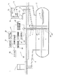
図1は、本発明の地下タンクの漏洩検査方法に用いる漏洩検査システムの実施例の構成図である。図1は、本発明の地下タンクの漏洩検査方法に用いる漏洩検査システムを、車両等に燃料を供給するための給油所に適用した例を示す。 FIG. 1 is a configuration diagram of an embodiment of a leakage inspection system used in the underground tank leakage inspection method of the present invention. FIG. 1 shows an example in which the leakage inspection system used in the underground tank leakage inspection method of the present invention is applied to a gas station for supplying fuel to vehicles and the like.
本実施例の漏洩検査システム20は、給油所1に設けられた地下タンク2内に挿入されて地下タンク2に生じた漏洩箇所の開口部を検出する検査プロ一ブ21や、この検査プロ一ブ21に組み込まれた液面変位速度センサ22及びマイクロホン23から供給される信号を検出・処理し、表示・記録・出力、及び判定等を行う計測制御装置24等によって構成される測定系と、検査条件を設定又は実施するために地下タンク2を密閉し気相部Gを減圧するための継ぎ手71、減圧ホース72、減圧ポンプ73及び圧力計75等からなる設備系に大別される。
The
このように構成された本実施例の漏洩検査システム20の各部について説明する前に、本実施例の漏洩検査システム20が適用される給油所1の構成について、まず説明する。
Before describing each part of the
図1において、地下タンク2には、油液3が貯留され、内部には、液相部Lと気相部Gとが形成されている。4は地下タンク2にタンクローリ車等から油液を補給するための注入管で、一端が注入口4aとなり、他端が地下タンク2内の底部側に位置して開口している。注油口4aは、通常、油液の補給時以外は、蓋部材5によって気密に施蓋されている。6は地下タンク2内の油液を吸上げるための吸入管で、一端が地下タンク2内の底部側に位置して開口し、他端が計量機7に接続されている。計量機7は、計量機本体内にポンプ及び流量計を内蔵し、地下タンク2からポンプにより吸い上げた油液を流量計によって計量し、図示せぬ給油ホース先端に設けられた給油ノズルから車両の燃料タンク等に油液を供給する構成になっている。計量機7のポンプ吸込み側の流路部分には、ポンプの吸込みヘッド圧を確保するための逆止弁(図示省略)が配設されており、地下タンク2の漏洩検査時には、この逆止弁は地下タンク2内の圧力が負圧になるため閉弁し、自動的に吸入管6の他端を外部に対して閉塞可能になっている。
In FIG. 1, an
8は、地下タンク2の上部に埋設された金属製又はコンクリート製の埋設ボックス(マンホールプロテクタ)で、地表に開口した開口部はマンホール蓋(図示省略)によって施蓋されている。埋設ボックス8内には、検尺棒,液面計のフロート等を地下タンク2内に挿入するため計量管9の計量口9aが開口している。この計量口9aは、蓋部材、又は当該計量口9aに装着された液面計本体によって、常時は気密に施蓋されている。
Reference numeral 8 denotes a metal or concrete burying box (manhole protector) embedded in the upper part of the
10は、一端が通気口10aとなり、他端が地下タンク2内の上部側に連通して設けられた通気管である。通気管10は、地下タンク2内の油蒸気を外部に逃がす。
次に、上述した給油所1を例に、本実施例の漏洩検査システム20の設備系及び測定系各部構成について説明する。
Next, the configuration of each part of the equipment system and the measurement system of the
設備系において、減圧ポンプ73は、地下タンク2内の気相部Gの気体を外部に排出して、地下タンク2内を減圧する。減圧ポンプ73の吸引側は、減圧ホース72を介して、通気管10の通気口10aと継ぎ手71を介して気密に接続される。この減圧ホース72の途中には、地下タンク2内の温度状態を測定するための温度計74、地下タンク2内の減圧状態を測定するための圧力計75が設けられている。減圧ポンプ73によって吸引された地下タンク2内の気相部Gの気体は、不活性ガスを混合する等して安全・環境面の処置がなされた後、大気開放ホース76を介して放出される。
In the equipment system, the
一方、測定系において、検査プロ一ブ21は、液面変位速度センサ22及びマイクロホン23を備え、検査時には、計量口9aから計量管9を介して地下タンク2内に挿入配置される。液面変位速度センサ22は、液面レベルの変動に伴って発生する流量センサを通過する液体の流れの量を計測する。液面変位速度センサ22には、本実施例の場合は、熱交換式流量センサが用いられている。液面変位速度センサ22の検出信号は、検査プロ一ブ21の長さ方向に延設したケーブル25内の信号線を介して差圧伝送器26に接続されている。そして、差圧伝送器26によって信号処理が施された後、計測制御装置24に供給される。マイクロホン23は、地下タンク2内の音を集音して電気音響信号に変換する。マイクロホン23には、本実施例の場合は、耐油性の防食構造を備えた圧電型のマイクロホンが用いられている。マイクロホン23から出力される電気音響信号は、同じくケーブル25内の信号線を介して、安全保持器付音声変換器27と、安全保持器28を介してI/F変換器(電流/周波数変換器)29とに供給される。安全保持器付音声変換器27は、マイクロホン23から出力される電気音響信号を音声信号に変換し、スピーカから音声出力する。また、I/F変換器29は、マイクロホン23から出力される電気音響信号を周波数分析するための周波数信号に変換する。
On the other hand, in the measurement system, the
計測制御装置24は、本実施例の場合は、パーソナルコンピュータによって構成され、漏洩検査の検査状況や測定結果を監視・出力するためのディスプレイ装置やプリンタ等といった出力手段30や、漏洩検査のための各種データや測定結果を蓄積するための記憶手段31や、漏洩検査実施に当たって各種データを設定入力するためのキーボード等からなる入力手段32が備えられている。計測制御装置24は、差圧伝送器26を介して供給される地下タンク2内で液面変位速度センサ22によって検出した地下タンク2内の液面変位に基づく流量検出信号や、I/F変換器29を介して供給される周波数信号に変換された地下タンク2内でマイクロホン23により検出した電気音響信号に基づいて、地下タンク2内に生じた開口部(漏洩箇所)の有無等を検査する。
In the case of the present embodiment, the
また、計測制御装置24は、漏洩検査を実施するに際して、後述するように、地下タンク2内の気相部Gを減圧する圧力の大きさを、タンク容量(タンク寸法)、危険物の液面位(タンク底面から液面までの高さ)、及び危険物の密度から計算して設定し、さらには地下タンク2の周りの地下水位(タンク底面から地下水面までの高さ)を加味して計算して設定する減圧圧力演算手段として機能する。
In addition, when performing the leak test, the
以上のように構成された本実施例の漏洩検査システム20では、密閉された地下タンク2内を減圧ポンプ73を作動して減圧することによって負圧状態とし、地下水または空気の浸入を液相部Lに挿入した液面変位速度センサ22とマイクロホン23により検知することにより、液相部L及び地下水位より下部の直径0.3mm以下の開口部からの漏洩の有無を検査する地下タンクの漏洩検査方法を実施できるものである。
In the
次に、液相部L及び地下水位より下部の直径0.3mm以下の開口部からの漏洩の有無を検査するための地下タンクの漏洩検査方法、特にその際における地下タンク2内の気相部Gを減圧する圧力の大きさの設定について説明する。
Next, a leakage inspection method for an underground tank for inspecting whether there is leakage from the liquid phase portion L and an opening having a diameter of 0.3 mm or less below the groundwater level, particularly the gas phase portion in the
本実施の形態による地下タンクの漏洩検査方法では、直径0.3mm以下の開口部から浸入する地下水、あるいは空気を確実に検知するため、タンク容量、貯蔵物の液面位、地下水位等の条件に従って適切な減圧値(負圧力)を設定する。 In the underground tank leakage inspection method according to this embodiment, in order to reliably detect groundwater or air entering from an opening having a diameter of 0.3 mm or less, conditions such as tank capacity, stored liquid level, groundwater level, etc. Set an appropriate reduced pressure value (negative pressure) according to.
このことにより、液相部Lに生じたタンク壁部の開口部すなわち漏洩箇所を介しての地下水の浸入は、液面変位速度センサ22で検知した信号を分析することにより、ある値以上の液面の上昇速度として捉え、また空気の浸入はマイクロホン23により採取した音声信号を分析することにより特異な周波数域の一定レベル以上の音として捉えることができる。
As a result, the intrusion of groundwater through the opening of the tank wall portion, that is, the leaked portion, generated in the liquid phase portion L can be detected by analyzing the signal detected by the liquid surface
ここでは、地下水の浸入を検出する液面変位速度センサ22の感度を0.02mm/h、マイクロホン23は0.3mmの開口部から空気の侵入音を捉える感度を持つものとして説明を行う。
Here, the description will be made on the assumption that the sensitivity of the liquid surface
まず、本実施の形態による地下タンクの漏洩検査方法のポイントである地下タンク2内を減圧する圧力の大きさについて説明する。図2〜4は、検査を実施する地下タンク2の危険物(油液)3の液面位と地下水位80との関係を示している。
First, the magnitude | size of the pressure which decompresses the inside of the
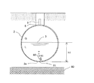
図2は、地下水位がタンクの底部より更に下方に存在する場合の地下タンクの漏洩状態の説明図である。 FIG. 2 is an explanatory diagram of the leakage state of the underground tank when the underground water level exists further below the bottom of the tank.
図2に示した如くの、地下水位80が地下タンク2の底部2eより更に下方に存在するような環境で検査を行った際に、地下タンク2の危険物3の液相部Lに開口部11が存在する場合には、当該開口部11からは空気85が浸入することになる。
When the inspection is performed in an environment where the
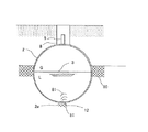
図3は、地下水位がタンクの危険物の液面より上方に存在する場合の地下タンクの漏洩状態の説明図である。 FIG. 3 is an explanatory diagram of the leakage state of the underground tank when the groundwater level exists above the level of the dangerous substance in the tank.
図3に示した如くの、地下水位80が地下タンク2の危険物3の液面より上方に存在するような環境で検査を行った際に、地下タンク2の危険物3の液相部Lに開口部12が存在する場合には、当該開口部12からは地下水81が浸入することになる。
When the inspection is performed in an environment where the
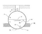
図4は、地下水位がタンクの底部より上方で、タンクの危険物の液面より下方にあって、タンクの底部と危険物の液面とのその中間に存在する場合の地下タンクの漏洩状態の説明図である。 FIG. 4 shows the leakage state of the underground tank when the groundwater level is above the bottom of the tank, below the level of the dangerous substance in the tank, and between the bottom of the tank and the level of the dangerous substance. It is explanatory drawing of.
図4に示した如くの、地下水位80が地下タンク2の底部2eより上方で、地下タンク2の危険物3の液面より下方にあって、地下タンク2の底部2eと危険物3の液面とのその中間に存在するような環境で検査を行った際に、地下タンク2の危険物3の液相部Lに開口部13,14が存在する場合には、当該開口部13,14の位置により、開口部13からは地下水81が、又開口部14からは空気85が浸入することになる。
As shown in FIG. 4, the
ここで、地下タンク2内を減圧する圧力の大きさを考えるに当たり、まず、図2に示すような、開口部11が地下タンク2の底部2eに存在し、開口部11の外側に地下水81がない場合を考える。
Here, in considering the magnitude of pressure for depressurizing the inside of the
地下タンク2内の気相部Gの圧力が大気圧で、地下タンク2の周囲も大気圧と想定すると、図2に示すように、開口部11には、地下タンク2の内側から外側に危険物3を排出しようとする圧力が働いている。
Assuming that the pressure of the gas phase portion G in the
この圧力の大きさH1は、危険物3の液位h1と密度ρ1を乗じた大きさになっている。この状態から地下タンク2内を減圧してタンク内の圧力が△H2になったとすると、開口部11に作用するヘッドH3は(H1−△H2)となる。
The magnitude H1 of this pressure is a magnitude obtained by multiplying the liquid level h1 of the
すなわち、地下タンク2内を減圧することにより、危険物3を排出する圧力は小さくなる。減圧する圧力が危険物3の液位h1と危険物の密度ρ1を乗じた大きさと等しくなった時、開口部11における危険物3を排出する圧力の大きさは0となり、それ以上減圧する圧力を大きくすると、逆に開口部11から空気85が浸入するようになる。
That is, by depressurizing the
したがって、図2のように空気85が浸入する場合の地下タンク2内の減圧する圧力の大きさHaは、式(1)に示す値を設定すればよい。
Ha=△(h1×ρ1+α) ・・・・・(1)
Therefore, the magnitude Ha of the pressure to be depressurized in the
Ha = Δ (h1 × ρ1 + α) (1)
式(1)におけるαは、検知する開口部11の大きさとマイクロホン23の感度によって決められる。
例えば、直径0.3ミリメートル以下の開口部11を確実に検知しようとする場合、通常の感度のマイクロホンを使用した場合には、4kPa程度の大きさになる。
Α in Expression (1) is determined by the size of the
For example, when an
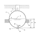
一方、図5に示すような、開口部15が地下タンク2の底部2eに存在し、開口部15の外側に地下水81がある場合を考える。
On the other hand, as shown in FIG. 5, consider a case where the
図5は、開口部が地下タンクの底部に存在し、開口部の外側に地下水がある場合の地下タンクの漏洩状態の説明図である。 FIG. 5 is an explanatory diagram of the leakage state of the underground tank when the opening exists at the bottom of the underground tank and there is groundwater outside the opening.
地下タンク2内の気相部Gの圧力が大気圧の時、開口部15には、地下タンク2の内側から外側に向かって圧力H3が働いている。この圧力H3の大きさは、式(2)に示すように、危険物3の液位h1と密度ρ1を乗じた値と地下水位h2に地下水の密度ρ2を乗じた値の差となっている。
H3=h1×ρ1−h2×ρ2 ・・・・・(2)
When the pressure of the gas phase part G in the
H3 = h1 × ρ1−h2 × ρ2 (2)
したがって、H3が正の値を取る場合には、開口部15を通して危険物3が地下タンク2の外に流出し、負の値を取る場合には、開口部15を通して地下水81が地下タンク2の中に浸入することになる。この場合、式(2)の正負に拘わらず、地下タンク2の気相部Gの圧力H4を式(3)で示す値まで減圧すれば、その時の開口部15に働く圧力H5は、式(4)に示す通りとなり負の値を取るため、開口部15を通して地下水81が地下タンク2内に浸入する条件となる。
H4=△(h1×ρ1) ・・・・・(3)
H5=H3+H4=△(h2×ρ2) ・・・・・(4)
Therefore, when H3 takes a positive value, the
H4 = Δ (h1 × ρ1) (3)
H5 = H3 + H4 = Δ (h2 × ρ2) (4)
式(4)の圧力の大きさが、地下水81を開口部15を通して地下タンク2内に浸入させる、いわゆるヘッドとなるが、微小な開口部から大気中にそのヘッドにより水が放出される時の流量Qは、良く知られているように式(5)で表される。
Q=CA√2ρgH×3600 ・・・・・(5)
ここで、Q:流量[ml/h]、C:流量係数(=0.815)、A:開口部断面積[Cm2]、ρ:水の比重(=1)、g:重力加速度[cm/s2](=980)、H:ヘッド[cm]、なお、“√2ρgH”は、“(2ρgH)1/2”を表わす。
The magnitude of the pressure of the formula (4) becomes a so-called head that allows the
Q = CA√2ρgH × 3600 (5)
Here, Q: flow rate [ml / h], C: flow coefficient (= 0.815), A: opening cross-sectional area [Cm 2 ], ρ: specific gravity of water (= 1), g: gravity acceleration [cm / s 2 ] (= 980), H: head [cm], and “√2ρgH” represents “(2ρgH) 1/2 ”.
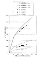
この状態に比べ、水が油中に放出された場合、出口付近での油分の粘性抵抗により微小な開口部を流れる流量は低下すると考えられたため、実際にガソリン中に微小孔から水を浸入させる実験を行った。 Compared to this state, when water was released into the oil, it was thought that the flow rate through the minute opening would decrease due to the viscous resistance of the oil near the outlet, so water actually entered the gasoline through the minute holes. The experiment was conducted.
図6は、ガソリン中に微小孔から水を浸入させる実験を行った結果のグラフである。
図中の実線は、各微小孔径について式(5)から計算した結果を示している。各孔径の場合も、流量は式(5)の計算結果に対して低下しており、この低下が粘性等による抵抗と考えると、実際の流量Q'は式(6)で表される。
Q'=FCA√2ρgH×3600 ・・・・・(6)
ここで、F:損失係数。
実験結果からFを求めると、F=0.75〜0.90となっている。
FIG. 6 is a graph showing a result of an experiment in which water is infiltrated into the gasoline through the minute holes.
The solid line in the figure indicates the result calculated from the equation (5) for each micropore diameter. Also in the case of each hole diameter, the flow rate is reduced with respect to the calculation result of Equation (5), and when this reduction is considered as resistance due to viscosity or the like, the actual flow rate Q ′ is expressed by Equation (6).
Q '= FCA√2ρgH × 3600 (6)
Where F: loss factor.
When F is obtained from the experimental results, F = 0.75 to 0.90.
0.02mm/hの液面変化をもたらす水の浸入量は、タンクの容量によって異なり、タンク容量が大きくなるに従って液面面積が増えるため、それだけ大きな量が必要となる。すなわち、点検するタンクの容量に従って、十分な液面変位をもたらす水準浸入するだけの点検圧力を設定する必要がある。 The amount of water that causes a liquid level change of 0.02 mm / h differs depending on the capacity of the tank, and the liquid surface area increases as the tank capacity increases. That is, it is necessary to set an inspection pressure sufficient to enter a level that causes a sufficient liquid level displacement according to the capacity of the tank to be inspected.
実際の水の浸入量は損失係数F=0.75として式(6)を用いて、各容量の代表的なストレートタンクの最大液面面積Smax(タンク中心)から、0.02mm/hの液面変位に必要な水の浸入量Qminを計算し、その浸入量が確保できるヘッドHminを孔径Φ0.3mmについて計算した結果を図7に示す。 The actual water intrusion amount is 0.02 mm / h from the maximum liquid surface area Smax (tank center) of a typical straight tank of each capacity using the equation (6) with a loss factor F = 0.75. FIG. 7 shows the result of calculating the water intrusion amount Qmin necessary for the surface displacement, and calculating the head Hmin that can secure the infiltration amount with respect to the hole diameter Φ0.3 mm.
図7は、各容量のストレートタンクに対する水の侵入に必要な圧力表である。
以上から、水が浸入する条件での、タンク内の減圧する圧力の大きさHdは、危険物の液位によるヘッド分(h1・ρ1)を打ち消し、さらにタンク容量に応じた十分な水の浸入を確保できるヘッドHminを加えた式(7)で示される値にすれば良いことが分かる。
Hd=△(h1×ρ1+Hmin) ・・・・・(7)
FIG. 7 is a pressure table necessary for water to enter the straight tank of each capacity.
From the above, the pressure Hd to reduce the pressure in the tank under the condition of water intrusion cancels out the head (h1 · ρ1) due to the liquid level of the dangerous substance, and further infiltration of sufficient water according to the tank capacity It can be seen that the value expressed by the expression (7) including the head Hmin that can secure the above is sufficient.
Hd = Δ (h1 × ρ1 + Hmin) (7)
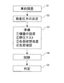
図8は、本発明による地下タンクの漏洩検査方法の一実施の形態のフローチャートである。 FIG. 8 is a flowchart of one embodiment of the underground tank leakage inspection method according to the present invention.
本発明による地下タンクの漏洩検査方法は、地下タンク2内の気相部Gを減圧することにより、開口部11〜15からの地下水、もしくは空気の浸入を促し、それを液面変位速度センサ22、及びマイクロホン23で検知する。直径0.3mm以下の開口部11〜15からの浸入を確実に検知するためには、液面変位速度センサ22、及びマイクロホン23で検知できるレベルの変化を起こすことが必要となる。このことから、気相部Gを負圧にする圧力の大きさが検査条件として重要となる。
In the underground tank leakage inspection method according to the present invention, the gas phase G in the
本方法では、この検査圧力の決定(ステップS2)を、事前調査(ステップS1)によって得られたタンクデータ等に基づいて決定する。 In this method, the determination of the inspection pressure (step S2) is determined based on the tank data obtained by the preliminary investigation (step S1).
一方、液面変位速度センサ22、及びマイクロホン23は所定の機能通りに動作し、適確にレベル検知することか求められる。このため、本方法では、ステップS3に示す準備段階に、(1)漏洩検査システム20を構成する各機器の設置工程,(3)給油所1の検査対象の地下タンク2と連通されている配管や機器等の各部の密閉処置工程,(4)その気密確認工程とともに、(2)液面変位速度センサ22、及びマイクロホン23のチェックを行う静圧テスト工程を設けている。
On the other hand, the liquid level
ステップS5の判定工程は、計測制御装置24に取り込まれた全ての検査結果から判断されて出力される。
The determination process of step S5 is determined and output from all the inspection results fetched by the
ステップS1の事前調査は、地下タンク2の漏洩検査試験を適正、かつ有効に実施するために行う調査で、地下タンク2の設置位置、危険物(油液)3の種類、及び地下タンク2の容量、寸法(内径、胴長、板厚)等を図面により確認した後、下記の調査を行う。この調査データは、例えば、入力手段32の操作によって計測制御装置(パソコン)24にマスターデータとして入力される。マスターデータとしては、
(1)地下タンク2の貯蔵量及び液の高さ
(2)GL(地表面)〜地下タンク2の底部2eまでの深さ
(3)GL〜地下水81までの深さ
(4)タンク内液温、等
があり、記憶手段31に登録される。
The preliminary survey in step S1 is a survey conducted in order to properly and effectively carry out the leak inspection test of the
(1) Storage amount of
マスターデータとして登録された事前調査データから、計測制御装置(パソコン)24ンは検査圧力を決定する。 The measurement control device (personal computer) 24 determines the inspection pressure from the preliminary survey data registered as the master data.
検査圧力の算出の基本的な考え方は前述の通りであるが、地下水の浸入がある場合と無い場合とで以下の通りとなる。 The basic idea for calculating the inspection pressure is as described above, and is as follows depending on whether or not groundwater has entered.
(1)地下水位がタンク底面より下方にある場合(地下水の浸入がない場合)
Pd=△1・(ρc・hc/10.2+4.0) ・・・・・(8)
ここで、Pd:設定圧力(負圧)[kPa]、ρc:タンク貯蔵物の比重、hc:タンク貯蔵物の液位(タンク底面からの高さ)[cm]。
(1) When the groundwater level is below the tank bottom (when there is no ingress of groundwater)
Pd = Δ1 · (ρc · hc / 10.2 + 4.0) (8)
Here, Pd: set pressure (negative pressure) [kPa], ρc: specific gravity of tank stock, hc: liquid level of tank stock (height from tank bottom) [cm].
(2)地下水位がタンク底面より上方にある場合(水の浸入がある場合)
Pd=△1・(ρc・hc/10.2+Ha) ・・・・・(9)
ここで、Pa:設定圧力(負圧)[kPa]、ρc:タンク貯蔵物の比重、hc:タンク貯蔵物の液位[cm]、Ha:タンク容量に応じて付加する圧力[kPa]、(図7に示した圧力表の値[kPa])。
(2) When the groundwater level is above the bottom of the tank (when water enters)
Pd = Δ1 · (ρc · hc / 10.2 + Ha) (9)
Here, Pa: set pressure (negative pressure) [kPa], ρc: specific gravity of tank stock, hc: liquid level [cm] of tank stock, Ha: pressure [kPa] applied according to tank capacity, ( Value of pressure table shown in FIG. 7 [kPa]).
したがって、上述した式(8)及び式(9)、加えて図7に示した如くの各容量のストレートタンクに対する地下水位の浸入に必要な圧力表を、計測制御装置24に接続された記憶手段31に登録しておくことによって、ストレートタンクの漏洩検査の実施の際、入力手段32によって、検査対象の地下タンク2について地下水位がタンク底面より下方にあるか上方にあるかを選択設定した上、検査対象の地下タンク2に貯蔵された貯蔵物の比重ρc、及びタンク貯蔵物の液位を設定するだけで、地下タンク2内の気相部Gを減圧する圧力の適確な大きさを演算して取得することができる。この取得した気相部Gの減圧値は、出力手段30から表示または印刷出力される。また、例えば、減圧ホース72に開閉弁77を設け、この開閉弁77及び減圧ポンプ73を計測制御装置24に備えられた制御端に接続し、減圧ポンプ73のマニュアル操作によらず、計測制御装置24によって開閉弁77及び減圧ポンプ73を作動制御し、気相部Gの取得した減圧値に気相部がなるように圧力計75に基づき自動制御する構成にすることも可能である。
Therefore, the storage means connected to the
次に、本発明の地下タンクの漏洩検査方法に用いる漏洩センサ装置としての検査プローブ21の構成について、図面により説明する。
Next, the configuration of the
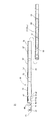
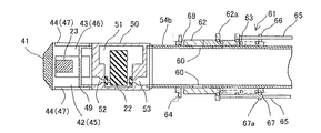
図9,図10は、本発明の地下タンクの漏洩検査方法に用いる漏洩センサ装置としての検査プローブの一実施例の構成図である。 9 and 10 are configuration diagrams of an embodiment of an inspection probe as a leakage sensor device used in the underground tank leakage inspection method of the present invention.
図9は、漏洩センサ装置としての検査プローブの全体構成図である。
図10は、図9に示した検査プローブの先端側部分の拡大図である。なお、図10において、図10(A)は検査プローブの先端側部分の拡大平面図を、図10(B)は検査プローブの先端側部分の拡大正面図を、図10(C)は図10(A)に記載したX−X矢視方向の断面図をそれぞれ示したものである。
FIG. 9 is an overall configuration diagram of an inspection probe as a leakage sensor device.
FIG. 10 is an enlarged view of the tip side portion of the inspection probe shown in FIG. 10A is an enlarged plan view of the distal end portion of the inspection probe, FIG. 10B is an enlarged front view of the distal end portion of the inspection probe, and FIG. 10C is FIG. Sectional drawing of the XX arrow direction described in (A) is each shown.
検査プローブ21は、図1で説明したように、計量口9aから計量管9に挿入されて地下タンク2内に設けられるため、円筒形状の細長筐体部40によって構成されている。
As described with reference to FIG. 1, the
検査プローブ21の細長筐体部40の先端面(挿入端面)には、地下タンク2への挿入の際にタンク内壁と衝突してタンク内壁を傷つけるのを防止するとともに、その衝撃から検査プローブ21の細長筐体部40内に実装された液面変位速度センサ22(図10(C)参照)やマイクロホン23を保護するための弾性体からなる保護部材41が設けられている。保護部材41は、検査プローブ21の先端を構成する。保護部材41は、細長筐体部40の先端側に形成されたマイクロホン収納筐体部42の軸方向端部に取り付けられている。マイクロホン収納筐体部42は、マイクロホン23を収容するマイクロホン収納室43が内部に形成され、その周面にはこのマイクロホン収納室43を外部すなわち地下タンク2内に対して開放するための複数の集音窓部44が形成されている。これにより、収納室43に設けられたマイクロホン23も外部(地下タンク2内)に臨むようになっている。
The distal end surface (insertion end surface) of the
このマイクロホン収納筐体部42に隣接して検査プローブ21の基端側方向には、液面変位速度センサ22の流入口室を形成するフィルタ収納筐体部45が形成されている。フィルタ収納筐体部45も、フィルタ収納室46が内部に形成され、その周面にはこの収納室46を外部すなわち地下タンク2内に対して開放するための複数の流入窓47が形成されている。そして、フィルタ収納室46には、コイルバネ48によって検査プローブ21の基端側方向に付勢指示されて円筒フィルタ49が配置されている。
A
また、フィルタ収納筐体部45に隣接して検査プローブ21の基端側方向には、液面変位速度センサ22が内部に収容されたセンサ収納筐体部50が形成されている。液面変位速度センサ収納部50の内部には、液面変位速度センサ22を構成する流量センサ(熱線式流量センサ)が収容されているセンサ収納室51が形成されている。液面変位速度センサ収納部50には、検査プローブ21の軸方向に沿って挿入端側に延びるオリフィス流入路52が形成され、フィルタ収納筐体部45に設けられた円筒フィルタ49のコイルバネ48側とは反対側の軸方向流出口に液面変位速度センサ22の流入側が連通しているとともに、検査プローブ21の軸方向に沿って基端側に延びるオリフィス流出路53によって、液面変位速度センサ22の流出側が後述する流路管部54内に形成された液蓄積空間に連通している。
In addition, a
そして、これらマイクロホン収納筐体部42、フィルタ収納筐体部45、及びセンサ収納筐体部50は、検査プローブ21の細長筐体部40の挿入端側部分に配置されている。
これに対し、検査プローブ21の細長筐体部40のセンサ収納筐体部50よりも基端側の部分は、内部に液蓄積空間が形成された流路管部54(図9参照)になっている。流路管部54は本実施の形態の場合、複数段の円筒管の連結構成からなり、挿入される地下タンク2の直径(深さ)等に応じてその連結長さを調整することによって、各種タンクに適応できるようになっている。その上で、この細長筐体部40における流路管部54の検査プローブ21の基端側の円筒管54aには、図9に示すように周回りに4個ずつ1組の連通孔55が検査プローブ21の軸方向に間隔を空けて4組、計16個の連通孔55が設けられ、流路管部54内の液蓄積空間を外部(地下タンク2内の気相部G)と連通するようになっている。この円筒管54aの外周には、ゴミ除け様のカバー54が巻装されて連通孔55は覆われ、外部から異物が流路管部54内の液蓄積空間に入らないようになっている。ところで、検査プローブ21を地下タンク2に挿入して取り付けると、前述した液面変位速度センサ22部分及びこの流路管部54内の液蓄積空間はエアーリッチ、一方、地下タンク2の気相部Gはベーパーリッチになる。このため、液面変位速度センサ22部分及びこの流路管部54内の液蓄積空間と地下タンク2の気相部Gとの間に圧力差が生じ、地下タンク2に漏洩箇所の開口部が開いていないのに拘わらず、地下タンク2の気相部Gから液面変位速度センサ22を介して流路管部54内の液蓄積空間内に油液が流れ込む現象が生じようとする。連通孔55は、その際に、液面変位速度センサ22部分及びこの流路管部54内の液蓄積空間と地下タンク2の気相部Gとの間に圧力差を速やかに解消するように作用する。
The
On the other hand, the portion of the
56は液面変位速度センサ22やマイクロホン23からの信号線が内蔵された信号線ケーブル(前述のケーブル25と同一)である。信号線ケーブルは検査プローブ21の細長筐体部40外周に装着された熱収縮性チューブ57によって固定され、基端側に導出されている。
続いて、図11,図12より、本発明の地下タンクの漏洩検査方法に用いる漏洩センサ装置としての検査プローブの他の実施例について説明する。なお、その説明に当たっては、図9,図10に示した漏洩センサ装置と同一な構成部分については、同一の符号を付してその説明を省略する。 Next, another embodiment of an inspection probe as a leakage sensor device used in the underground tank leakage inspection method of the present invention will be described with reference to FIGS. In the description, the same components as those of the leakage sensor device shown in FIGS. 9 and 10 are denoted by the same reference numerals, and the description thereof is omitted.
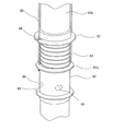
図11は、漏洩センサ装置としての検査プローブの別の実施例の構成図である。
図12は、漏洩センサ装置としての検査プローブの別の実施例の要部外観図である。
FIG. 11 is a configuration diagram of another embodiment of an inspection probe as a leakage sensor device.
FIG. 12 is an external view of the main part of another embodiment of an inspection probe as a leakage sensor device.
まず、本実施の形態の形態の漏洩センサ装置としての検査プローブ21は、マイクロホン収納筐体部42とフィルタ収納筐体部45とが位置の筐体部によって構成され、これに関係して、マイクロホン収納室43とフィルタ収納室46、集音窓部44と流入窓47が共用化された構成になっている。
First, the
そして、本実施の形態の検査プローブ21においては、センサ収納筐体部50に隣接した流路管部54の中、センサ収納筐体部50に連結された円筒管54bに、当該円筒管54b内の液蓄積空間を外部(地下タンク2内の気相部G)と連通する連通孔60が例えば周回りに4個設けられ、さらにこの連通孔60を連通・遮断する開閉弁部61が備えられていることを特徴とする。本実施例の開閉弁部61は、円筒管54bの外周を摺動可能に設けられ、連通孔60をその摺動に応じて開閉する弁体部62と、弁体部62を閉弁するように付勢する円筒管54bの外周に巻回されたコイルスプリング63と、コイルスプリング63の付勢力による弁体部62の移動を規制するために円筒管54bに固定された位置決めリング64と、弁体部62に形成された鍔部62aに一端が固定され、他端が検査プローブ21の基端側へ延設された一対の索条65と、コイルスプリング63の移動を規制するとともにこの索条を案内するガイド溝66が形成された鍔部67aを備え、円筒管54bに固定された固定リング67と、弁体部62の閉弁状態を検出するための閉弁センサ68とを備えて構成されている。
In the
通常、検査プローブ21の挿入端を地下タンク2内の液相Lに侵漬させた際は、液面変位速度センサ22の流入側と流出側との間は、当該センサ(熱線式流量計)22の細い(例えば、直径0.8mm)通路によってのみ連通される状態であるため、危険物としての油液が円筒管54b内の液蓄積空間69内に進入する(円筒外すなわち地下タンク2内の液相Lと同じ液面レベルにするまで)のに時間がかかる。
Normally, when the insertion end of the
本実施の検査プローブ21によれば、検査プローブ21を地下タンク2内に挿入した後、一対の索条65を引き、弁体部62を開放させて、油液をセンサ22上部の円筒管54b内の液蓄積空間69内に速やかに侵入させることができる。そして、流路管部54の液蓄積空間69内の液面と、地下タンク2の液面とが同一レベルになると、連通孔60を閉塞させる。連通孔60が確実に閉塞されているか否かは鍔部67aの上面に設けている閉弁センサ(例えば、圧力感知センサ)68がONになっていることで判断する。
According to the
また、前述したように、センサ22の測定管路の径を細くすれば流量計の分解能が上がり、微小な液面変位、すなわち微小な漏洩も検知することができる。ところで、センサ22の測定管路の径を細くするにつれ、前述したステップS3の準備段階の(1)で説明した、漏洩検査システム20を構成する各機器の設置工程で検査プローブ21を地下タンク2内の液相Lに侵漬させたときに、このセンサ22の内部通路にエアー(微少な気泡)が付着して残留し易くなる傾向もある。このような場合には、センサ22の原点(ゼロ点)がでにくくなる可能性が考えられる。そこで、このような場合には、検査プローブ21を地下タンク2内に挿入した後に、センサ22の上部に地下タンク2内の液体が満たされた状態で、所定圧力の窒素ガスを筒部上部に間歇的に封入するこれにより、センサ22の上部(下流)に貯留している液体を介してセンサ22の内部通路およびセンサ22の通路下部の液体に振動を与え、センサ22の通路下部に混入したエアーを排出でき、センサ22の性能確保にも貢献できる。この場合の窒素ガスには、減圧ポンプ73によって吸引された地下タンク2内の気相部Gの気体を放出するときに利用する不活性ガスを転用することも可能である。
Further, as described above, if the diameter of the measurement pipe of the
1 給油所
2 地下タンク
3 油液
4 注入管
5 蓋部材
6 吸入管
7 計量機
8 埋設ボックス
9 計量管
10 通気管
11 開口部
20 漏洩検査システム
21 検査プロ一ブ
22 液面変位速度センサ
23 マイクロホン
24 計測制御装置
25 ケーブル
26 差圧伝送器
27 安全保持器付音声変換器
28 安全保持器
29 I/F変換器
30 出力手段
31 記憶手段
32 入力手段
71 継ぎ手
72 減圧ホース
73 減圧ポンプ
74 温度計
75 圧力計
76 大気開放ホース
80 地下水位
81 地下水
85 空気
DESCRIPTION OF
Claims (8)
危険物が通過する際の変位を検出するセンサを内蔵した検査プローブを地下タンクに挿入して当該地下タンクの漏洩を検査するために減圧する圧力の大きさを、タンクの形状容量、危険物の液面の高さ、及び危険物の密度から計算して設定する圧力演算ステップと、
当該地下タンク内の圧力を当該地下タンクに連通させて設けた圧力計測手段及び減圧手段によって設定値に減圧する減圧ステップと
を有することを特徴とする地下タンクの漏洩検査方法。 An underground tank leakage inspection method for inspecting leakage from an opening generated in a wall of an underground tank for storing dangerous materials,
Insert a test probe with a built-in sensor to detect displacement when dangerous materials pass into the underground tank, and determine the amount of pressure to depressurize in order to check for leaks in the underground tank. A pressure calculation step that is calculated and set from the height of the liquid level and the density of dangerous materials;
A leak inspection method for an underground tank, comprising: a pressure measuring means provided by communicating the pressure in the underground tank with the underground tank; and a pressure reducing step for reducing the pressure to a set value by a pressure reducing means.
危険物が通過する際の変位を検出するセンサを内蔵した検査プローブを地下タンクに挿入して当該地下タンクの漏洩を検査するために減圧する圧力の大きさを、タンクの形状容量、危険物の液面の高さ、危険物の密度、及び地下タンクの周りの地下水位から計算して設定する圧力演算ステップと、
当該地下タンク内の圧力を当該地下タンクに連通させて設けた圧力計測手段及び減圧手段によって設定値に減圧する減圧ステップと
を有することを特徴とする地下タンクの漏洩検査方法。 An underground tank leakage inspection method for inspecting leakage from an opening generated in a wall of an underground tank for storing dangerous materials,
Insert a test probe with a built-in sensor to detect displacement when dangerous materials pass into the underground tank, and determine the amount of pressure to depressurize in order to check for leaks in the underground tank. A pressure calculation step that is calculated and set from the height of the liquid level, the density of dangerous materials, and the groundwater level around the underground tank;
A leak inspection method for an underground tank, comprising: a pressure measuring means provided by communicating the pressure in the underground tank with the underground tank; and a pressure reducing step for reducing the pressure to a set value by a pressure reducing means.
地下水位が当該地下タンクの底面以上の高さ位置に存在する場合に、開口部から浸入する地下水により上昇する当該地下タンクの液面レベルの上昇速度が、予め定められた速度以上となるような地下水の浸入量が確保できる大きさの減圧圧力値を計算して設定する
ことを特徴とする請求項1又は2記載の地下タンクの漏洩検査方法。 The pressure calculating step includes
When the groundwater level is higher than the bottom surface of the underground tank, the rising speed of the liquid level of the underground tank rising by the groundwater entering from the opening is higher than a predetermined speed. 3. The underground tank leakage inspection method according to claim 1 or 2, wherein a reduced pressure value is calculated and set so as to secure a groundwater infiltration amount.
開口部の直径が0.3mmで、当該開口部から浸入した地下水の量を当該地下タンクの液面位の液面面積で除した値が毎時0.02mm以上となる地下水の浸入を可能ならしめるような地下水浸入のためのヘッド圧力を確保できる大きさの減圧圧力値を計算して設定する
ことを特徴とする請求項1又は2記載の地下タンクの漏洩検査方法。 The pressure calculating step includes
The diameter of the opening is 0.3 mm, and the amount of groundwater that has entered through the opening is divided by the liquid surface area of the liquid level of the underground tank, so that intrusion of groundwater is possible at 0.02 mm per hour or more. 3. The underground tank leakage inspection method according to claim 1, wherein a pressure reduction value having a magnitude capable of securing a head pressure for infiltration of groundwater is calculated and set.
地下水位が当該地下タンクの底面より下方に存在する場合に、危険物の液面位にその密度を乗じて求めた圧力に、4kPa以上を加えた圧力の大きさの負圧を減圧圧力値として計算して設定する
ことを特徴とする請求項1又は2記載の地下タンクの漏洩検査方法。 The pressure calculating step includes
When the groundwater level is below the bottom of the underground tank, the pressure obtained by multiplying the liquid level of the dangerous material by its density and adding 4 kPa or more to the negative pressure is the reduced pressure value. The underground tank leakage inspection method according to claim 1, wherein the method is set by calculation.
危険物が通過する際の変位を検出するセンサとともにマイクロホンを挿入端側に配置して内蔵し、地下タンクに設けられた計量口から当該地下タンク内に挿入可能な検査プローブによって構成される
ことを特徴とする漏洩センサ装置。 A leakage sensor device used in a leakage inspection method for an underground tank or the like for inspecting leakage from an opening generated on a wall surface of an underground tank for storing dangerous materials,
A microphone is installed on the insertion end side along with a sensor that detects the displacement when dangerous materials pass, and is configured by an inspection probe that can be inserted into the underground tank from the weighing port provided in the underground tank. Leak sensor device characterized.
危険物が通過する際の変位を検出するセンサを挿入端側に配置して内蔵し、地下タンクに設けられた計量口から当該地下タンク内に挿入可能な検査プローブによって構成され、当該検査プローブには、挿入端側から離間した地下タンク内の危険物に侵漬されない高さ位置に、当該地下タンク内と前記センサの危険物の通過出口に連通した当該漏洩検査プローブ内とを連通する連通孔を設けた
ことを特徴とする漏洩センサ装置。 A leakage sensor device used in a leakage inspection method for an underground tank or the like for inspecting leakage from an opening generated on a wall surface of an underground tank for storing dangerous materials,
A sensor for detecting the displacement when dangerous materials pass is arranged on the insertion end side and built in, and it is composed of an inspection probe that can be inserted into the underground tank from the weighing port provided in the underground tank. Is a communication hole that communicates the inside of the underground tank and the inside of the leakage inspection probe that communicates with the passage of dangerous substances through the sensor at a height that is not immersed in the dangerous material in the underground tank that is spaced from the insertion end side. A leakage sensor device characterized by comprising:
挿入端側の地下タンク内の危険物に侵漬される高さ位置に、当該地下タンク内と前記センサの危険物の通過出口に連通した当該漏洩検査プローブ内とを連通する連通孔を設けると共に、該連通孔を連通・遮断する弁手段を設けた
ことを特徴とする請求項6又は7記載の漏洩センサ装置。 In the leak inspection probe,
At the height position where the dangerous substance in the underground tank on the insertion end side is immersed, there is provided a communication hole that communicates the inside of the underground tank and the leak inspection probe that communicates with the passage of dangerous substances through the sensor. 8. The leak sensor device according to claim 6, further comprising valve means for communicating / blocking the communication hole.
Priority Applications (1)
| Application Number | Priority Date | Filing Date | Title |
|---|---|---|---|
| JP2004111469A JP4338572B2 (en) | 2004-04-05 | 2004-04-05 | Leak inspection method and leak sensor device for underground tank |
Applications Claiming Priority (1)
| Application Number | Priority Date | Filing Date | Title |
|---|---|---|---|
| JP2004111469A JP4338572B2 (en) | 2004-04-05 | 2004-04-05 | Leak inspection method and leak sensor device for underground tank |
Publications (2)
| Publication Number | Publication Date |
|---|---|
| JP2005292091A true JP2005292091A (en) | 2005-10-20 |
| JP4338572B2 JP4338572B2 (en) | 2009-10-07 |
Family
ID=35325164
Family Applications (1)
| Application Number | Title | Priority Date | Filing Date |
|---|---|---|---|
| JP2004111469A Expired - Fee Related JP4338572B2 (en) | 2004-04-05 | 2004-04-05 | Leak inspection method and leak sensor device for underground tank |
Country Status (1)
| Country | Link |
|---|---|
| JP (1) | JP4338572B2 (en) |
Cited By (4)
| Publication number | Priority date | Publication date | Assignee | Title |
|---|---|---|---|---|
| JP2007121208A (en) * | 2005-10-31 | 2007-05-17 | Tokiko Techno Kk | Underground tank leak inspection method |
| JP2008058153A (en) * | 2006-08-31 | 2008-03-13 | Tokiko Techno Kk | Leakage test system for underground tank |
| JP2015148560A (en) * | 2014-02-07 | 2015-08-20 | 富士電機株式会社 | Heat exchanger thin tube leak detection device and leak detection method |
| CN113776757A (en) * | 2021-09-17 | 2021-12-10 | 大连船舶重工集团有限公司 | Leakage monitoring and processing system of B-type independent storage cabin |
Families Citing this family (1)
| Publication number | Priority date | Publication date | Assignee | Title |
|---|---|---|---|---|
| CN106197890A (en) * | 2016-07-12 | 2016-12-07 | 潜江菲利华石英玻璃材料有限公司 | A kind of detection method of quartz glass ingot melting tremie pipe |
-
2004
- 2004-04-05 JP JP2004111469A patent/JP4338572B2/en not_active Expired - Fee Related
Cited By (5)
| Publication number | Priority date | Publication date | Assignee | Title |
|---|---|---|---|---|
| JP2007121208A (en) * | 2005-10-31 | 2007-05-17 | Tokiko Techno Kk | Underground tank leak inspection method |
| JP2008058153A (en) * | 2006-08-31 | 2008-03-13 | Tokiko Techno Kk | Leakage test system for underground tank |
| JP2015148560A (en) * | 2014-02-07 | 2015-08-20 | 富士電機株式会社 | Heat exchanger thin tube leak detection device and leak detection method |
| CN113776757A (en) * | 2021-09-17 | 2021-12-10 | 大连船舶重工集团有限公司 | Leakage monitoring and processing system of B-type independent storage cabin |
| CN113776757B (en) * | 2021-09-17 | 2023-09-01 | 大连船舶重工集团有限公司 | Leakage monitoring processing system of B-type independent storage cabin |
Also Published As
| Publication number | Publication date |
|---|---|
| JP4338572B2 (en) | 2009-10-07 |
Similar Documents
| Publication | Publication Date | Title |
|---|---|---|
| US8234911B2 (en) | Method and apparatus for detecting a leak in a double pipe | |
| US11060944B2 (en) | Leak detection installation, method, usage and corresponding computer program storage means | |
| JP4499332B2 (en) | Method for inspecting and locating leaks and apparatus suitable for carrying out the method | |
| KR100309361B1 (en) | Leak Detection Method and Device | |
| RU2545355C2 (en) | Method of functional test of leak detector | |
| US10215656B2 (en) | Systems and methods for liquid dynamic pressure testing | |
| JPS59170739A (en) | Leak inspecting method of tank | |
| JP4374241B2 (en) | System and method for measuring the sealability of an object | |
| CN106461488B (en) | Pressure grading element | |
| JP4338572B2 (en) | Leak inspection method and leak sensor device for underground tank | |
| JPH0231332B2 (en) | ||
| CN104246131B (en) | Sealing structure, delivery device with sealing structure, and method of operating the sealing structure | |
| KR100573426B1 (en) | Mobile Leak Detection Device for Oil Storage Tanks | |
| US7216530B2 (en) | Fluid containment element leak detection apparatus and method | |
| JP4206498B2 (en) | Liquid storage tank leak detection system | |
| JP4795775B2 (en) | Underground tank leak inspection method | |
| JP4336236B2 (en) | Tank leak detection device | |
| JP4968668B2 (en) | Leak inspection device for housing etc. | |
| JP2009198323A (en) | Method, apparatus and system for seal inspection | |
| US7143636B2 (en) | Field device for determining and/or monitoring a process variable | |
| US12480834B2 (en) | System for detecting leaks and associated method | |
| JP3430975B2 (en) | Leak tester | |
| JP2008058153A (en) | Leakage test system for underground tank | |
| JP4257396B2 (en) | Underground tank leak test equipment | |
| JP2002054972A (en) | Pressure level gauge |
Legal Events
| Date | Code | Title | Description |
|---|---|---|---|
| A621 | Written request for application examination |
Free format text: JAPANESE INTERMEDIATE CODE: A621 Effective date: 20070226 |
|
| A521 | Request for written amendment filed |
Free format text: JAPANESE INTERMEDIATE CODE: A821 Effective date: 20070227 |
|
| A977 | Report on retrieval |
Free format text: JAPANESE INTERMEDIATE CODE: A971007 Effective date: 20081219 |
|
| TRDD | Decision of grant or rejection written | ||
| A01 | Written decision to grant a patent or to grant a registration (utility model) |
Free format text: JAPANESE INTERMEDIATE CODE: A01 Effective date: 20090623 |
|
| A01 | Written decision to grant a patent or to grant a registration (utility model) |
Free format text: JAPANESE INTERMEDIATE CODE: A01 |
|
| A61 | First payment of annual fees (during grant procedure) |
Free format text: JAPANESE INTERMEDIATE CODE: A61 Effective date: 20090630 |
|
| R150 | Certificate of patent or registration of utility model |
Ref document number: 4338572 Country of ref document: JP Free format text: JAPANESE INTERMEDIATE CODE: R150 Free format text: JAPANESE INTERMEDIATE CODE: R150 |
|
| FPAY | Renewal fee payment (event date is renewal date of database) |
Free format text: PAYMENT UNTIL: 20120710 Year of fee payment: 3 |
|
| FPAY | Renewal fee payment (event date is renewal date of database) |
Free format text: PAYMENT UNTIL: 20130710 Year of fee payment: 4 |
|
| S533 | Written request for registration of change of name |
Free format text: JAPANESE INTERMEDIATE CODE: R313533 |
|
| R350 | Written notification of registration of transfer |
Free format text: JAPANESE INTERMEDIATE CODE: R350 |
|
| R250 | Receipt of annual fees |
Free format text: JAPANESE INTERMEDIATE CODE: R250 |
|
| R250 | Receipt of annual fees |
Free format text: JAPANESE INTERMEDIATE CODE: R250 |
|
| R250 | Receipt of annual fees |
Free format text: JAPANESE INTERMEDIATE CODE: R250 |
|
| R250 | Receipt of annual fees |
Free format text: JAPANESE INTERMEDIATE CODE: R250 |
|
| S533 | Written request for registration of change of name |
Free format text: JAPANESE INTERMEDIATE CODE: R313533 |
|
| R350 | Written notification of registration of transfer |
Free format text: JAPANESE INTERMEDIATE CODE: R350 |
|
| R250 | Receipt of annual fees |
Free format text: JAPANESE INTERMEDIATE CODE: R250 |
|
| LAPS | Cancellation because of no payment of annual fees |