JP2005292066A - Condition diagnosis apparatus, condition diagnosis program, and condition diagnosis system. - Google Patents
Condition diagnosis apparatus, condition diagnosis program, and condition diagnosis system. Download PDFInfo
- Publication number
- JP2005292066A JP2005292066A JP2004110678A JP2004110678A JP2005292066A JP 2005292066 A JP2005292066 A JP 2005292066A JP 2004110678 A JP2004110678 A JP 2004110678A JP 2004110678 A JP2004110678 A JP 2004110678A JP 2005292066 A JP2005292066 A JP 2005292066A
- Authority
- JP
- Japan
- Prior art keywords
- pixels
- diagnosis
- image
- value
- state
- Prior art date
- Legal status (The legal status is an assumption and is not a legal conclusion. Google has not performed a legal analysis and makes no representation as to the accuracy of the status listed.)
- Pending
Links
Images

Landscapes
- Image Analysis (AREA)
- Testing Of Devices, Machine Parts, Or Other Structures Thereof (AREA)
- Investigating Materials By The Use Of Optical Means Adapted For Particular Applications (AREA)
- Air Conditioning Control Device (AREA)
- Image Processing (AREA)
Abstract
【課題】 外観の状態が変化する部材の診断において信頼性を向上させることが可能な状態診断装置、プログラムおよびシステムを提供する。
【解決手段】 外観の状態が変化するエアフィルタ5の診断を行う携帯診断装置120であって、画像撮影部121と、診断部133とを備えている。画像撮影部121は、外観の状態が変化するエアフィルタ5の画像を取得する。診断部133は、診断値に基づいてエアフィルタ5の状態診断を行う。ここでの診断値は、画像を構成する各画素に対して2つの値のいずれかを割り当てる二値化処理を施して二値化画像を作成して、この二値化画像を所定のブロックに分割し、所定のブロックに関するデータを利用することにより求める。
【選択図】 図4PROBLEM TO BE SOLVED: To provide a state diagnosis apparatus, a program and a system capable of improving reliability in diagnosis of a member whose appearance changes.
A portable diagnostic device 120 that diagnoses an air filter 5 whose appearance changes, and includes an image capturing unit 121 and a diagnostic unit 133. The image capturing unit 121 acquires an image of the air filter 5 whose appearance changes. The diagnosis unit 133 performs a state diagnosis of the air filter 5 based on the diagnosis value. The diagnostic value here is a binarized image obtained by applying a binarization process that assigns one of two values to each pixel constituting the image, and this binarized image is stored in a predetermined block. It is obtained by dividing and using data relating to a predetermined block.
[Selection] Figure 4
Description
本発明は、外観の状態が変化する部材の診断を行う状態診断装置、状態診断プログラムおよび状態診断システムに関する。 The present invention relates to a state diagnosis device, a state diagnosis program, and a state diagnosis system for diagnosing a member whose appearance changes.
従来から、一般住宅やオフィスなどの屋内において調和された空気を屋内に供給することにより屋内の快適性を向上させる空気調和装置が知られている。この空気調和装置には、空気調和装置の稼働に伴って徐々に消耗、劣化したり汚れたりする消耗部品が用いられている。このため、空気調和装置を適切に稼働できる状態に保つためには、これらの消耗部品を洗浄したり交換したりする等の適切な処置を行う必要がある。 2. Description of the Related Art Conventionally, an air conditioner that improves indoor comfort by supplying indoor air conditioned indoors such as a general house or an office is known. This air conditioner uses consumable parts that gradually wear out, deteriorate or become dirty as the air conditioner operates. For this reason, in order to keep the air conditioner in an appropriately operable state, it is necessary to take appropriate measures such as cleaning or replacing these consumable parts.
例えば、空気調和装置には、空気中に含まれる埃や塵などの微粒子を低減させて空気の清浄化を行う上記消耗部品としてのフィルタが用いられている。このフィルタには、空気調和装置が運転されることにより多くの微粒子が蓄積されていくが、このような多くの微粒子が蓄積された状態のフィルタを用いて空気調和装置を運転させると、送風機構における負担が大きくなったり空気清浄効果が得られにくくなったりする等、空気調和装置を適切に運転することが困難になる。このため、フィルタに多くの微粒子が蓄積してくると上述した洗浄や交換等を行うフィルタのメンテナンス作業が必要となるが、ユーザ等はメンテナンス時期になっていることに気付きにくく、空気調和装置に負担を掛け続けて空気清浄効果が低減した状態での運転を続けてしまうことがある。 For example, an air conditioner uses a filter as the consumable part that cleans air by reducing particulates such as dust and dust contained in the air. When the air conditioner is operated, many fine particles are accumulated in this filter. When the air conditioner is operated using a filter in which such many fine particles are accumulated, a blower mechanism It becomes difficult to properly operate the air conditioner, such as increasing the burden on the air conditioner or making it difficult to obtain an air cleaning effect. For this reason, when a large amount of fine particles accumulates in the filter, it is necessary to perform maintenance work on the filter that performs the above-described cleaning and replacement. The operation may be continued in a state where the air purification effect is reduced by continuously applying a burden.
これに対して、以下に示す特許文献1においては、このようなフィルタのメンテナンス時期を、空気調和装置の稼働時間等から判断して、ユーザ等に報知する空気調和装置が提案されている。
ところが、上述した特許文献1で示された方法によって判断する場合であっても、調和対象となる空気の汚染度合い等によってフィルタの汚染進行度合いが異なり、メンテナンス時期はまちまちとなる等、空気調和装置の稼働時間からメンテナンス時期を一律に判断する方法では、その診断結果が信頼性に欠けたものとなるおそれがある。
これに対して、ユーザやサービスエンジニア等がフィルタ等の消耗部品の状態を目視によって判断することも可能である。しかし、消耗部品のメンテナンス時期について、熟練された技術や卓越した知識を有するサービスエンジニアによる診断と未熟な技術で知識も不足しているサービスエンジニアによる診断との食い違いが生じる等、一定の基準による安定した診断を行うことが困難な場合がある。
However, even if it is a case where it judges by the method shown by the
On the other hand, a user, a service engineer, or the like can visually determine the state of a consumable part such as a filter. However, there is a discrepancy in the maintenance period of consumable parts, such as a discrepancy between a diagnosis by a service engineer who has skilled technology and excellent knowledge, and a diagnosis by a service engineer who has insufficient skills due to inexperienced technology. It may be difficult to make a diagnosis.
本発明の課題は、外観の状態が変化する部材の診断において信頼性を向上させることが可能な状態診断装置、プログラムおよびシステムを提供することにある。 An object of the present invention is to provide a state diagnosis device, a program, and a system capable of improving reliability in diagnosis of a member whose appearance changes.
請求項1に記載の状態診断装置は、外観の状態が変化する部材の診断を行う状態診断装置であって、取得部と、診断部とを備えている。取得部は、外観の状態が変化する部材の画像を取得する。診断部は、診断値に基づいて部材の状態診断を行う。ここでの診断値は、画像を構成する各画素に対して2つの値のいずれかを割り当てる二値化処理を施して二値化画像を作成して、この二値化画像を所定のブロックに分割し、所定のブロックに関するデータを利用することにより求める。
The state diagnosis apparatus according to
従来のように、ユーザやサービスエンジニア等の目視によって部材のメンテナンスを行うタイミングを判断する場合には、熟練された技術や知識を有するサービスエンジニアによる診断と未熟なサービスエンジニアによる診断との食い違いが生じる等、一定の基準による安定した診断を行うことが困難になる場合がある。
しかし、請求項1に記載の状態診断装置では、取得部が部材の状態が示された画像を取得して、診断部が二値化画像を作成して、ブロックに分割し、各ブロックに関するデータを利用して得られる診断値に基づいて診断を行っている。すなわち、診断部における診断において、部材の状態が一定の判断手法によって反映された値を用いることができる。したがって、統一された判断手法に従って部材の状態診断を行うことが可能になり、診断における信頼性を向上させることが可能になる。例えば、上述した状態診断によると、状態診断に個人的な主観が含まれることを抑えることができるようになる。
As in the prior art, when the timing of maintenance of a member is visually determined by a user, a service engineer, etc., there is a discrepancy between a diagnosis by a service engineer who has skilled technology and knowledge and a diagnosis by an inexperienced service engineer. For example, it may be difficult to perform a stable diagnosis based on a certain standard.
However, in the state diagnosis apparatus according to
請求項2に記載の状態診断装置は、請求項1に記載の状態診断装置であって、診断部は、近傍大型ブロックの数と、近傍小型ブロックの数とに対して重み付けをして得られる値に基づいて診断値を求める。ここでの近傍大型ブロックとは、二値化画像において所定の距離以内の近傍に位置する同じ値の画素によって構成されるブロックに含まれる画素数が第1画素数以上の近傍ブロックのうち、第1画素数よりも大きい第2画素数以上の画素数を有するブロックのことをいう。また、近傍小型ブロックとは、二値化画像において所定の距離以内の近傍に位置する同じ値の画素によって構成されるブロックに含まれる画素数が第1画素数以上の近傍ブロックのうち、第2画素数に満たない画素数を有するブロックのことをいう。なお、ここでの近傍大型ブロックや近傍小型ブロックについては、例えば、一方の値が割り当てられた画素が他方の値が割り当てられた互いに近傍に位置している画素によって囲まれている場合には、一方の値の画素についても上記他方の値の画素から構成されるブロックの画素数のカウントに含まれるとして、各ブロックを捕らえることになる。また、上記近傍に位置する画素の所定の距離は、例えば、部材の種類や、部材の耐久性等によって定めることができる。
The condition diagnosis apparatus according to
ここでは、例えば、一方の値が割り当てられた画素が多数存在する場合であっても、その一方の値が割り当てられた画素から構成されるブロックのうち、大きなブロックが比較的多く存在するように変化した場合と小さなブロックが比較的多く存在するように変化した場合とで、部材の状態変化の度合いが異なることがある。
これに対して、請求項2に記載の状態診断装置では、診断部が、近傍大型ブロックの数と、近傍小型ブロックの数とに対して重み付けをして得られる値に基づいて診断値を求めることで診断を行う。このように、近傍大型ブロックと近傍小型ブロックとを分けて捕らえて、部材の状態診断において寄与度の異なる両ブロックについて、それぞれ重み付けを施すことにより、部材のより詳細な状態を診断値に反映させることができるようになる。したがって、より詳細な状態診断を行うことが可能になる。
Here, for example, even when there are a large number of pixels to which one value is assigned, there is a relatively large number of large blocks among the blocks composed of pixels to which the one value is assigned. The degree of change in the state of the member may be different between the case where the change has occurred and the case where the change has occurred so that there are relatively many small blocks.
On the other hand, in the state diagnosis apparatus according to
なお、例えば、ここでは、ブロックに含まれる画素数が第1画素数に満たないような小さなブロックについては、診断値に反映させにくいようにすることが可能になる。これによって、状態診断において悪影響を与えうるようなノイズ等が診断値に反映されてしまうことを抑えることができるようになる。
また、ここでは、例えば、一方の値が割り当てられた画素から成るブロックに、所定の近傍距離以内に存在する他方の値が割り当てられた画素をも含めているため、各のブロック毎について、マクロな視点による概略を把握できるようになる。これにより、診断値に診断対象の状態についての概略を反映させることができるようになる。
Note that, for example, a small block in which the number of pixels included in the block is less than the first pixel number can be made difficult to be reflected in the diagnostic value. As a result, it is possible to prevent the noise or the like that may have an adverse effect in the state diagnosis from being reflected in the diagnosis value.
In addition, here, for example, a block composed of pixels to which one value is assigned includes a pixel to which the other value existing within a predetermined neighborhood distance is assigned. It will be possible to grasp the outline from a simple viewpoint. Thereby, the outline about the state of the diagnosis target can be reflected in the diagnosis value.
請求項3に記載の状態診断装置は、請求項2に記載の状態診断装置であって、少なくとも第1画素数と第2画素数とのいずれか一方は、部材の性質、画像の撮影時における位置、画像の撮影時における距離あるいは画像の撮影時における角度に基づいて定める。なお、ここでの部材の性質としては、例えば、部材の形状に基づく値等が含まれる。具体的には、撮影対象の部材がフィルタである場合には、フィルタの網目を構成する格子間隔の距離等が挙げられる。また、撮影時の画像の位置、距離あるいは角度としては、例えば、撮影カメラが固定されている場合に画像フレームの中の部材もしくは所定のブロックが写っている位置や、撮影時のカメラと部材との間の距離や、方向が観念される部材の場合には正面からのズレの角度等が含まれる。
The condition diagnosis apparatus according to
ここでは、近傍小型ブロックであるための閾値となる第1画素数と、近傍大型ブロックであるための閾値となる第2画素数との少なくともいずれか一方が、部材の性質や画像の撮影時における状況等に基づいて定められる。このため、第1画素数と第2画素数との少なくともいずれか一方を、部材毎や撮影状況毎に定めることができるようになるため、より適切な診断値を得ることが可能になる。例えば、汚れや不具合について判断される基準が部材毎に異なる場合であっても、第1画素数や第2画素数を部材毎に定めることで、診断値に反映されるブロックの画素数を調整することが可能となり、より適切な診断値を得ることができるようになる。 Here, at least one of the first pixel number serving as the threshold value for the neighborhood small block and the second pixel number serving as the threshold value for the neighborhood large block is determined by the property of the member or the time of shooting the image. It is determined based on the situation. For this reason, since at least one of the first pixel number and the second pixel number can be determined for each member or for each photographing condition, a more appropriate diagnostic value can be obtained. For example, even when the criteria for judging dirt and defects differ for each member, the number of pixels of the block reflected in the diagnostic value is adjusted by determining the first pixel number and the second pixel number for each member. It becomes possible to obtain a more appropriate diagnostic value.
請求項4に記載の状態診断装置は、請求項1に記載の状態診断装置であって、診断部は、隣接大型ブロックの数と、隣接小型ブロックの数とに重み付けをして得られる値に基づいて診断値を求める。ここでの隣接大型ブロックは、二値化画像において隣接して連なる同じ値の画素数が第3画素数以上である隣接ブロックのうち、第3画素数よりも大きい第4画素数以上の画素数を有するブロックのことをいう。また、隣接小型ブロックは、二値化画像において隣接して連なる同じ値の画素数が第3画素数以上である隣接ブロックのうち、第4画素数に満たない画素数を有するブロックのことをいう。
The condition diagnosis apparatus according to
ここでは、例えば、一方の値が割り当てられた画素が多数存在する場合であっても、その一方の値が割り当てられた画素から構成されるブロックのうち、大きなブロックが比較的多く存在するように変化した場合と小さなブロックが比較的多く存在するように変化した場合とで、部材の状態変化の度合いが異なることがある。
これに対して、請求項4に記載の状態診断装置では、診断部が、隣接大型ブロックの数と、隣接小型ブロックの数とに対して重み付けをして得られる値に基づいて診断値を求めることで診断を行う。このように、隣接大型ブロックと隣接小型ブロックとを分けて捕らえて、部材の状態診断において寄与度の異なる両ブロックについて、それぞれ重み付けを施すことにより、部材のより詳細な状態を診断値に反映させることができるようになる。したがって、より詳細な状態診断を行うことが可能になる。
Here, for example, even when there are a large number of pixels to which one value is assigned, there is a relatively large number of large blocks among the blocks composed of pixels to which the one value is assigned. The degree of change in the state of the member may be different between the case where the change has occurred and the case where the change has occurred so that there are relatively many small blocks.
On the other hand, in the state diagnosis apparatus according to
なお、ここでは、例えば、ブロックに含まれる画素数が第3画素数に満たないような小さなブロックについては、診断値に反映させにくくすることが可能になる。このため、状態診断において悪影響を与えうるようなノイズ等が診断に反映されてしまうことを抑えることができるようになる。
請求項5に記載の状態診断装置は、請求項4に記載の状態診断装置であって、少なくとも第3画素数と第4画素数とのいずれか一方は、部材の性質、画像の撮影時における位置、画像の撮影時における距離あるいは画像の撮影時における角度に基づいて定める。なお、ここでの部材の性質としては、例えば、部材の形状に基づく値等が含まれる。具体的には、撮影対象の部材がフィルタである場合には、フィルタの網目を構成する格子間隔の距離等が挙げられる。また、撮影時の画像の位置、距離あるいは角度としては、例えば、撮影カメラが固定されている場合に画像フレームの中の部材もしくは所定のブロックが写っている位置や、撮影時のカメラと部材との距離や、方向が観念される部材の場合には正面からのズレの角度や等が含まれる。
Here, for example, a small block in which the number of pixels included in the block is less than the third pixel number can be made difficult to be reflected in the diagnostic value. For this reason, it is possible to suppress noise and the like that may adversely affect the state diagnosis from being reflected in the diagnosis.
The condition diagnosis apparatus according to
ここでは、隣接小型ブロックであるための閾値となる第3画素数と、隣接大型ブロックであるための閾値となる第4画素数との少なくともいずれか一方が、部材の性質や画像の撮影時における状況等に基づいて定められる。このため、第3画素数と第4画素数との少なくともいずれか一方を部材毎や撮影状況毎に応じて定めることができるようになるため、より適切な診断値を得ることが可能になる。例えば、汚れや不具合について判断される基準が部材毎に異なる場合であっても、第3画素数や第4画素数を部材毎に定めることで、診断値に反映されるブロックの画素数を調整することが可能となり、より適切な診断値を得ることができるようになる。 Here, at least one of the third pixel number serving as a threshold value for an adjacent small block and the fourth pixel number serving as a threshold value for an adjacent large block depends on the property of the member and the time of shooting an image. It is determined based on the situation. For this reason, since at least one of the third pixel number and the fourth pixel number can be determined for each member or each photographing situation, a more appropriate diagnostic value can be obtained. For example, even if the criteria for judging dirt and defects differ for each member, the number of pixels of the block reflected in the diagnostic value is adjusted by determining the third pixel number and the fourth pixel number for each member. It becomes possible to obtain a more appropriate diagnostic value.
請求項6に記載の状態診断装置は、請求項1に記載の状態診断装置であって、診断部は、ブロック毎におけるいずれか一方の値が割り当てられている画素数に関する二値化画像の標準偏差に基づいて診断値を求める。ここでの標準偏差は、画像全体における一方の値が割り当てられた画素の分布の偏り度合いを表す指標となる。すなわち、ここでの標準偏差を算出するには、まず、一方の値が割り当てられている画素数をブロック毎に求め、この画素数の平均値を算出する。次に、この平均値とブロックにおける一方の値が割り当てられている画素数との差の二乗を、ブロック毎に求めて、その合計値を算出する。そして、得られた値をブロック数で除した値に対して平方根を算出して、標準偏差が求められる。標準偏差が小さい場合には、画像全体における一方の値が割り当てられた画素の分布の偏り度合いが小さいことを示す。標準偏差が大きい場合には、画像全体における一方の値が割り当てられた画素の分布の偏り度合いが大きいことを示す。
The condition diagnosis apparatus according to
ここでは、例えば、一方の値が割り当てられた画素が比較的多く存在する場合であっても、その一方の値が割り当てられた画素の分布の状況によっては、部材全体としての実際の状態変化の程度が少なかったり、逆に程度が大きかったりする等、状態変化の程度が異なることがある。
これに対して、請求項6に記載の状態診断装置では、診断部が、画像全体におけるいずれか一方の値が割り当てられている画素に関する標準偏差を診断値に反映させている。このため、画像全体における一方の値が割り当てられている画素数の分布の偏り度合いを反映させて、部材の状態診断をより詳細にすることが可能になる。
Here, for example, even when there are a relatively large number of pixels to which one value is assigned, depending on the distribution state of the pixels to which the one value is assigned, the actual state change of the entire member may be changed. The degree of state change may be different, for example, the degree may be small or conversely large.
On the other hand, in the state diagnosis apparatus according to the sixth aspect, the diagnosis unit reflects the standard deviation regarding the pixel to which any one value in the entire image is assigned to the diagnosis value. For this reason, it becomes possible to make the state diagnosis of the member more detailed by reflecting the degree of deviation of the distribution of the number of pixels to which one value in the entire image is assigned.
請求項7に記載の状態診断装置は、請求項1から6のいずれか1項に記載の状態診断装置であって、診断部は、面積率に基づいて診断値を求める。ここでの面積率とは、二値化画像の全画素数に対する二値化画像のうちのいずれか一方の値が割り当てられた画素数の割合のことをいう。
ここでは、所定のブロックに関するデータを利用するだけでなく、さらに面積率に基づいて診断値を求める。このため、部材の状態がより詳細に反映された診断値を得ることができるようになり、より詳細な状態診断を行うことが可能になる。
A condition diagnosis apparatus according to a seventh aspect is the condition diagnosis apparatus according to any one of the first to sixth aspects, wherein the diagnosis unit obtains a diagnosis value based on the area ratio. Here, the area ratio refers to the ratio of the number of pixels to which any one of the binarized images is assigned to the total number of pixels of the binarized image.
Here, not only data on a predetermined block is used, but also a diagnostic value is obtained based on the area ratio. For this reason, it becomes possible to obtain a diagnostic value in which the state of the member is reflected in more detail, and a more detailed state diagnosis can be performed.
請求項8に記載の状態診断装置は、請求項1から7のいずれか1項に記載の状態診断装置であって、データベースをさらに備えている。このデータベースは、部材の状態に対応する数値データを複数有している。そして、診断部は、診断値に基づいた診断において、データベースを参照する。
ここでは、診断部が部材の診断を行う際に、データベースに格納されている複数のデータと診断値を比較して診断することができるようになり、より信頼性の高い診断が可能になる。
A state diagnosis apparatus according to an eighth aspect is the state diagnosis apparatus according to any one of the first to seventh aspects, further comprising a database. This database has a plurality of numerical data corresponding to the state of the member. And a diagnostic part refers to a database in the diagnosis based on a diagnostic value.
Here, when the diagnosis unit diagnoses a member, it is possible to make a diagnosis by comparing a plurality of data stored in the database with a diagnosis value, and a more reliable diagnosis is possible.
請求項9に記載の状態診断装置は、請求項1から8のいずれか1項に記載の状態診断装置であって、部材には、フィルタ、空気調和装置に用いられるドレンパンおよび熱交換器が含まれる。
ここでは、画像を取得する対象の部材が、フィルタや、空気調和装置に用いられるドレンパンや熱交換器等の場合であっても、状態を診断する場合の信頼性を向上させることができるようになる。
The condition diagnosis apparatus according to claim 9 is the condition diagnosis apparatus according to any one of
Here, even when the member from which the image is acquired is a filter, a drain pan used in an air conditioner, a heat exchanger, or the like, the reliability when diagnosing the state can be improved. Become.
請求項10に記載の状態診断プログラムは、外観の状態が変化する部材の画像を、演算処理を行う処理器に処理させる状態診断プログラムであって、第1ステップから第5ステップの5つのステップを備えている。第1ステップでは、処理器に部材の画像を取得させる。第2ステップでは、処理器に、画像の画素に対して2つの値のいずれかを割り当てる二値化処理を行わせて二値化画像を作成させる。第3ステップでは、処理器に二値化画像を所定のブロックに分割させる。第4ステップでは、処理器に所定のブロックに関するデータを利用して診断値を求めさせる。第5ステップでは、処理器に、診断値に基づいた部材の状態診断を行わせる。すなわち、例えば、状態診断データ等の作成を行わせる。
The state diagnosis program according to
従来のように、ユーザやサービスエンジニア等の目視によって部材のメンテナンスを行うタイミングを判断する場合には、熟練された技術や知識を有するサービスエンジニアによる診断と未熟なサービスエンジニアによる診断との食い違いが生じる等、一定の基準による安定した診断を行うことが困難になる場合がある。
しかし、請求項10に記載の状態診断プログラムでは、この状態診断プログラムが実行されることにより、処理器が、第1ステップで部材の状態が示された画像を取得し、第2ステップで二値化画像を作成して、第3ステップで所定のブロックに分割し、第4ステップで診断値を求め、第5ステップで診断値に基づいて診断を行う。すなわち、状態診断プログラムが実行されることにより、部材の状態が一定の判断手法によって反映された診断値に基づいて、処理器に部材の状態を診断させることができる。したがって、統一された判断手法に従って部材の状態診断を行うことが可能になり、診断における信頼性を向上させることが可能になる。例えば、上述した状態診断によると、状態診断に個人的な主観が含まれることを抑えることができるようになる。
As in the prior art, when the timing of maintenance of a member is visually determined by a user, a service engineer, etc., there is a discrepancy between a diagnosis by a service engineer who has skilled technology and knowledge and a diagnosis by an inexperienced service engineer. For example, it may be difficult to perform a stable diagnosis based on a certain standard.
However, in the state diagnosis program according to
請求項11に記載の状態診断プログラムは、請求項10に記載の状態診断プログラムであって、第3ステップにおける所定のブロックは、隣接大型ブロックと、隣接小型ブロックとである。そして、第4ステップにおいて、処理器に、隣接大型ブロックの数と、隣接小型ブロックの数とに対して重み付けをして得られる値に基づいて診断値を求めさせる。ここで、隣接大型ブロックは、二値化画像において隣接して連なる同じ値の画素数が第3画素数以上である隣接ブロックのうち、第3画素数よりも大きい第4画素数以上の画素数を有するブロックのことをいう。また、隣接小型ブロックは、二値化画像において隣接して連なる同じ値の画素数が第3画素数以上である隣接ブロックのうち、第4画素数に満たない画素数を有するブロックのことをいう。
The condition diagnosis program according to claim 11 is the condition diagnosis program according to
ここでは、例えば、一方の値が割り当てられた画素が同様に多数存在する場合であっても、その一方の値が割り当てられた画素から構成されるブロックのうち、大きなブロックが比較的多く存在するように変化した場合と小さなブロックが比較的多く存在するように変化した場合とで、部材の状態変化の度合いが異なることがある。
これに対して、請求項11に記載の状態診断プログラムでは、第4ステップにおいて、処理器に、隣接大型ブロックの数と、隣接小型ブロックの数とに対して重み付けをして得られる値に基づいて診断値を求めさせている。このように、隣接大型ブロックと隣接小型ブロックとを分けて捕らえて、部材の状態診断において寄与度の異なる両ブロックについて、それぞれ重み付けを施すことにより、部材のより詳細な状態を診断値に反映させることができるようになる。したがって、より詳細な状態診断を行うことが可能になる。
Here, for example, even when there are a large number of pixels to which one value is assigned, there are relatively many large blocks among blocks composed of pixels to which the one value is assigned. The degree of change in the state of the member may be different between the case where the change is made in this way and the case where the change is made so that there are relatively many small blocks.
On the other hand, in the state diagnosis program according to claim 11, in the fourth step, the processor is based on a value obtained by weighting the number of adjacent large blocks and the number of adjacent small blocks. Diagnostic value. In this way, the adjacent large block and the adjacent small block are separately captured and weighted with respect to both blocks having different degrees of contribution in the member state diagnosis, thereby reflecting the more detailed state of the member in the diagnosis value. Will be able to. Therefore, a more detailed state diagnosis can be performed.
なお、ここでは、例えば、ブロックに含まれる画素数が第3画素数に満たないような小さなブロックについては、診断値に反映させにくいようにすることが可能になる。これによって、状態診断において悪影響を与えうるようなノイズ等が診断値に反映されてしまうことを抑えることができる。
請求項12に記載の状態診断プログラムは、請求項10に記載の状態診断プログラムであって、第4ステップでは、処理器に、所定のブロック毎におけるいずれか一方の値が割り当てられている画素数に関する二値化画像の標準偏差に基づいて診断値を求めさせる。ここでの標準偏差は、画像全体における一方の値が割り当てられた画素の分布の偏り度合いを表す指標となる。すなわち、ここでの標準偏差を算出するには、まず、一方の値が割り当てられている画素数をブロック毎に求め、この画素数の平均値を算出する。次に、この平均値とブロックにおける一方の値が割り当てられている画素数との差の二乗を、ブロック毎に求めて、その合計値を算出する。そして、得られた値をブロック数で除した値に対して平方根を算出して、標準偏差が求められる。標準偏差が小さい場合には、画像全体における一方の値が割り当てられた画素の分布の偏り度合いが小さいことを示す。標準偏差が大きい場合には、画像全体における一方の値が割り当てられた画素の分布の偏り度合いが大きいことを示す。
Here, for example, a small block in which the number of pixels included in the block is less than the third number of pixels can be made difficult to be reflected in the diagnostic value. As a result, it is possible to prevent the noise or the like that may adversely affect the state diagnosis from being reflected in the diagnosis value.
The state diagnosis program according to
ここでは、例えば、一方の値が割り当てられた画素が比較的多く存在する場合であっても、その一方の値が割り当てられた画素の分布の状況によっては、部材全体としての実際の状態変化の程度が少なかったり、逆に程度が大きかったりする等、状態変化の程度が異なることがある。
これに対して、請求項12に記載の状態診断プログラムでは、処理器に、画像全体におけるいずれか一方の値が割り当てられている画素に関する標準偏差に基づいて診断値を求めさせる。このため、画像全体における一方の値が割り当てられている画素数の分布の偏り度合いを反映させて、部材の状態診断をより詳細にすることが可能になる。
Here, for example, even when there are a relatively large number of pixels to which one value is assigned, depending on the distribution state of the pixels to which the one value is assigned, the actual state change of the entire member may be changed. The degree of state change may be different, for example, the degree may be small or conversely large.
On the other hand, in the state diagnosis program according to the twelfth aspect, the processor is caused to obtain a diagnosis value based on the standard deviation regarding the pixel to which any one value in the entire image is assigned. For this reason, it becomes possible to make the state diagnosis of the member more detailed by reflecting the degree of deviation of the distribution of the number of pixels to which one value in the entire image is assigned.
請求項13に記載の状態診断システムは、外観の状態が変化する部材の診断を行う状態診断システムであって、画像取得装置と、状態診断装置とを備えている。画像取得装置は、部材の画像を取得する。なお、ここでの画像取得装置としては、例えば、カメラ付き携帯電話端末等が含まれる。状態診断装置は、診断値に基づいて部材の状態診断を行う。ここでの診断値は、画像取得装置が取得した画像の画素に対して2つの値のいずれかを割り当てる二値化処理を施して二値化画像を作成し、二値化画像が分割された所定のブロックに関するデータを利用することにより求められる。なお、ここで、画像取得装置が取得した部材の画像を状態診断装置が取得するには、例えば、有線や無線の通信回線を介して受信して取得する場合や、記録媒体を介して取得する場合等が含まれる。 A state diagnosis system according to a thirteenth aspect is a state diagnosis system for diagnosing a member whose appearance changes, and includes an image acquisition device and a state diagnosis device. The image acquisition device acquires an image of the member. In addition, as an image acquisition apparatus here, a mobile telephone terminal with a camera etc. are contained, for example. The state diagnosis device performs a state diagnosis of the member based on the diagnosis value. The diagnostic value here is obtained by performing a binarization process that assigns one of two values to the pixels of the image acquired by the image acquisition device to create a binarized image, and the binarized image is divided It is obtained by using data relating to a predetermined block. Here, in order for the state diagnosis apparatus to acquire the image of the member acquired by the image acquisition apparatus, for example, when receiving and acquiring via a wired or wireless communication line, or via a recording medium Cases are included.
従来の診断システムにおいては、ユーザやサービスエンジニア等の目視によって部材のメンテナンスを行うタイミングを判断する場合には、熟練された技術や知識を有するサービスエンジニアによる診断と未熟なサービスエンジニアによる診断との食い違いが生じる等、一定の基準による安定した診断を行うことが困難になる場合がある。
しかし、請求項13に記載の状態診断システムでは、画像取得装置が部材の状態が示された画像を取得して、状態診断装置が二値化画像を作成して、ブロックに分割し、各ブロックに関するデータを利用して得られる診断値に基づいて診断を行っている。すなわち、診断部における診断において、部材の状態が一定の判断手法によって反映された値を用いることができる。したがって、統一された判断手法に従って部材の状態診断を行うことが可能になり、診断における信頼性を向上させることが可能になる。例えば、上述した状態診断によると、状態診断に個人的な主観が含まれることを抑えることができるようになる。
In a conventional diagnosis system, when judging the timing of maintenance of a member by visual observation by a user or service engineer, there is a discrepancy between a diagnosis by a service engineer who has skill and knowledge and a diagnosis by an inexperienced service engineer. In some cases, it may be difficult to perform a stable diagnosis based on a certain standard.
However, in the state diagnosis system according to claim 13, the image acquisition device acquires an image showing the state of the member, the state diagnosis device creates a binarized image, divides it into blocks, and each block Diagnosis is performed based on the diagnostic value obtained by using the data regarding. That is, in the diagnosis in the diagnosis unit, a value in which the state of the member is reflected by a certain determination method can be used. Therefore, it is possible to perform the state diagnosis of the member according to the unified determination method, and it is possible to improve the reliability in the diagnosis. For example, according to the above-described state diagnosis, it is possible to suppress the personal diagnosis from being included in the state diagnosis.
請求項14に記載の状態診断システムは、請求項13に記載の状態診断システムであって、状態診断装置は、隣接大型ブロックの数と、隣接小型ブロックの数とに対して重み付けをして得られる値に基づいて診断値を求める。ここでの隣接大型ブロックとは、二値化画像において隣接して連なる同じ値の画素数が第3画素数以上である隣接ブロックのうち、第3画素数よりも大きい第4画素数以上の画素数を有するブロックのことをいう。また、隣接小型ブロックとは、二値化画像において隣接して連なる同じ値の画素数が第3画素数以上である隣接ブロックのうち、第4画素数に満たない画素数を有するブロックのことをいう。 A condition diagnosis system according to a fourteenth aspect is the condition diagnosis system according to the thirteenth aspect, in which the condition diagnosis apparatus obtains weights for the number of adjacent large blocks and the number of adjacent small blocks. The diagnostic value is obtained based on the obtained value. Here, the adjacent large block is a pixel that is equal to or greater than the fourth pixel number larger than the third pixel number among adjacent blocks in which the number of pixels of the same value adjacent to each other in the binarized image is equal to or greater than the third pixel number. A block having a number. In addition, the adjacent small block is a block having the number of pixels less than the fourth pixel number among adjacent blocks in which the number of pixels of the same value adjacent to each other in the binarized image is equal to or greater than the third pixel number. Say.
ここでは、例えば、一方の値が割り当てられた画素が同様に多数存在する場合であっても、その一方の値が割り当てられた画素から構成されるブロックのうち、大きなブロックが比較的多く存在するように変化した場合と小さなブロックが比較的多く存在するように変化した場合とで、部材の状態変化の度合いが異なることがある。
これに対して、請求項14に記載の状態診断システムでは、状態診断装置が、隣接大型ブロックの数と、隣接小型ブロックの数とに対して重み付けをして得られる値に基づいて診断値を求めることで診断を行う。このように、隣接大型ブロックと隣接小型ブロックとを分けて捕らえて、部材の状態診断において寄与度の異なる両ブロックについて、それぞれ重み付けを施すことにより、部材のより詳細な状態を診断値に反映させることができるようになる。したがって、より詳細な状態診断を行うことが可能になる。
Here, for example, even when there are a large number of pixels to which one value is assigned, there are relatively many large blocks among blocks composed of pixels to which the one value is assigned. The degree of change in the state of the member may be different between the case where the change is made in this way and the case where the change is made so that there are relatively many small blocks.
On the other hand, in the state diagnosis system according to claim 14, the state diagnosis apparatus obtains a diagnosis value based on a value obtained by weighting the number of adjacent large blocks and the number of adjacent small blocks. Diagnose by asking. In this way, the adjacent large block and the adjacent small block are separately captured and weighted with respect to both blocks having different degrees of contribution in the member state diagnosis, thereby reflecting the more detailed state of the member in the diagnosis value. Will be able to. Therefore, a more detailed state diagnosis can be performed.
なお、ここでは、例えば、ブロックに含まれる画素数が第3画素数に満たないような小さなブロックについては、診断値に反映させにくいようにすることが可能になる。これによって、状態診断において悪影響を与えうるようなノイズ等が診断値に反映されてしまうことを抑えることができる。
請求項15に記載の状態診断システムは、請求項13に記載の状態診断システムであって、状態診断装置は、所定のブロック毎におけるいずれか一方の値が割り当てられている画素数に関する二値化画像の標準偏差に基づいて診断値を求める。ここでの標準偏差は、画像全体における一方の値が割り当てられた画素の分布の偏り度合いを表す指標となる。すなわち、ここでの標準偏差を算出するには、まず、一方の値が割り当てられている画素数をブロック毎に求め、この画素数の平均値を算出する。次に、この平均値とブロックにおける一方の値が割り当てられている画素数との差の二乗を、ブロック毎に求めて、その合計値を算出する。そして、得られた値をブロック数で除した値に対して平方根を算出して、標準偏差が求められる。標準偏差が小さい場合には、画像全体における一方の値が割り当てられた画素の分布の偏り度合いが小さいことを示す。標準偏差が大きい場合には、画像全体における一方の値が割り当てられた画素の分布の偏り度合いが大きいことを示す。
Here, for example, a small block in which the number of pixels included in the block is less than the third number of pixels can be made difficult to be reflected in the diagnostic value. As a result, it is possible to prevent the noise or the like that may adversely affect the state diagnosis from being reflected in the diagnosis value.
The state diagnosis system according to claim 15 is the state diagnosis system according to claim 13, wherein the state diagnosis apparatus binarizes the number of pixels to which any one value is assigned for each predetermined block. A diagnostic value is obtained based on the standard deviation of the image. The standard deviation here is an index representing the degree of bias of the distribution of the pixels to which one value in the entire image is assigned. That is, in order to calculate the standard deviation here, first, the number of pixels to which one value is assigned is obtained for each block, and the average value of the number of pixels is calculated. Next, the square of the difference between this average value and the number of pixels to which one value in the block is assigned is obtained for each block, and the total value is calculated. Then, the square root is calculated for the value obtained by dividing the obtained value by the number of blocks, and the standard deviation is obtained. When the standard deviation is small, it indicates that the degree of bias of the distribution of the pixels assigned with one value in the entire image is small. When the standard deviation is large, it indicates that the degree of bias of the distribution of pixels to which one value is assigned in the entire image is large.
ここでは、例えば、一方の値が割り当てられた画素が比較的多く存在する場合であっても、その一方の値が割り当てられた画素の分布の状況によっては、部材全体としての実際の状態変化の程度が少なかったり、逆に程度が大きかったりする等、状態変化の程度が異なることがある。
これに対して、請求項15に記載の状態診断システムでは、状態診断装置が、画像全体におけるいずれか一方の値が割り当てられている画素に関する標準偏差に基づいて診断値を求めることで診断を行う。このため、画像全体における一方の値が割り当てられている画素数の分布の偏り度合いを反映させて、部材の状態診断をより詳細にすることが可能になる。
Here, for example, even when there are a relatively large number of pixels to which one value is assigned, depending on the distribution state of the pixels to which the one value is assigned, the actual state change of the entire member may be changed. The degree of state change may be different, for example, the degree may be small or conversely large.
On the other hand, in the state diagnosis system according to claim 15, the state diagnosis device performs diagnosis by obtaining a diagnosis value based on a standard deviation regarding a pixel to which any one value in the entire image is assigned. . For this reason, it becomes possible to make the state diagnosis of the member more detailed by reflecting the degree of deviation of the distribution of the number of pixels to which one value in the entire image is assigned.
請求項1に係る状態診断装置では、統一された判断手法に従って部材の状態診断を行うことが可能になり、診断における信頼性を向上させることが可能になる。
請求項2に係る状態診断装置では、部材のより詳細な状態を診断値に反映させることができるようになり、より詳細な状態診断を行うことが可能になる。
請求項3に係る状態診断装置では、第1画素数と第2画素数との少なくともいずれか一方を部材毎や撮影状況毎に定めることができるようになり、より適切な診断値を得ることが可能になる。
In the state diagnosis apparatus according to the first aspect, it is possible to perform the state diagnosis of the member according to the unified determination method, and it is possible to improve the reliability in the diagnosis.
In the state diagnosis apparatus according to the second aspect, a more detailed state of the member can be reflected in the diagnosis value, and a more detailed state diagnosis can be performed.
In the state diagnosis apparatus according to the third aspect, at least one of the first pixel number and the second pixel number can be determined for each member or each photographing situation, and a more appropriate diagnostic value can be obtained. It becomes possible.
請求項4に係る状態診断装置では、部材の状態診断において寄与度の異なる各ブロックに対してそれぞれ重み付けを施すことにより、部材のより詳細な状態を診断値に反映させることができるようになり、より詳細な状態診断を行うことが可能になる。
請求項5に係る状態診断装置では、診断値に反映されるブロックの画素数を調整することが可能となり、より適切な診断値を得ることができるようになる。
In the state diagnosis apparatus according to
In the state diagnosis apparatus according to the fifth aspect, the number of pixels of the block reflected in the diagnostic value can be adjusted, and a more appropriate diagnostic value can be obtained.
請求項6に係る状態診断装置では、より詳細な状態診断を行うことが可能になる。
請求項7に係る状態診断装置では、診断値に対してさらに面積率を反映させることができ、部材の状態がより詳細に反映された状態診断を行うことが可能になる。
請求項8に係る状態診断装置では、データベースに格納されている複数のデータと診断値を比較して診断するため、より信頼性の高い診断が可能になる。
In the state diagnosis apparatus according to the sixth aspect, more detailed state diagnosis can be performed.
In the state diagnosis apparatus according to the seventh aspect, the area ratio can be further reflected on the diagnosis value, and the state diagnosis in which the state of the member is reflected in more detail can be performed.
In the state diagnosis apparatus according to the eighth aspect, diagnosis is performed by comparing a plurality of data stored in the database with the diagnosis value, so that diagnosis with higher reliability is possible.
請求項9に係る状態診断装置では、画像を取得する対象の部材が、フィルタや、空気調和装置に用いられるドレンパンや熱交換器等の場合であっても、状態を診断する場合の信頼性を向上させることができるようになる。
請求項10に係る状態診断プログラムでは、統一された判断手法に従って部材の状態診断を行うことが可能になり、診断における信頼性を向上させることが可能になる。
In the state diagnosis apparatus according to claim 9, even when the member for which an image is acquired is a filter, a drain pan or a heat exchanger used in an air conditioner, the reliability when diagnosing the state is improved. Can be improved.
In the state diagnosis program according to the tenth aspect, it is possible to perform the state diagnosis of the member according to the unified determination method, and it is possible to improve the reliability in the diagnosis.
請求項11に係る状態診断プログラムでは、この状態診断プログラムが実行されることにより、部材の状態診断において寄与度の異なる各ブロックに対してそれぞれ重み付けが施され、部材のより詳細な状態を診断値に反映させることができるようになり、より詳細な状態診断を行うことが可能になる。
請求項12に係る状態診断プログラムでは、より詳細な状態診断を行うことが可能になる。
In the state diagnosis program according to claim 11, by executing the state diagnosis program, each block having a different contribution degree is weighted in the member state diagnosis, and a more detailed state of the member is determined as a diagnosis value. This makes it possible to reflect this in a more detailed state diagnosis.
In the state diagnosis program according to the twelfth aspect, more detailed state diagnosis can be performed.
請求項13に係る状態診断システムでは、統一された判断手法に従って部材の状態診断を行うことが可能になり、診断における信頼性を向上させることが可能になる。
請求項14に係る状態診断システムでは、部材の状態診断において寄与度の異なる各ブロックに対してそれぞれ重み付けを施すことにより、部材のより詳細な状態を診断値に反映させることができるようになり、より詳細な状態診断を行うことが可能になる。
In the state diagnosis system according to the thirteenth aspect, the member state diagnosis can be performed according to the unified determination method, and the reliability in the diagnosis can be improved.
In the state diagnosis system according to claim 14, it is possible to reflect a more detailed state of the member in the diagnosis value by weighting each block having a different contribution degree in the state diagnosis of the member, More detailed state diagnosis can be performed.
請求項15に係る状態診断システムでは、より詳細な状態診断を行うことが可能になる。 In the state diagnosis system according to the fifteenth aspect, more detailed state diagnosis can be performed.
[第1実施形態]
本発明の第1実施形態に係る状態診断システムのブロック概略構成図を図1において示す。ここに示す状態診断システムは、主として空気調和装置のエアフィルタの状態診断を行い、その診断結果に対する処理態様をサービスエンジニアに対して報知させるためのシステムである。
[First Embodiment]
FIG. 1 shows a block schematic configuration diagram of the state diagnosis system according to the first embodiment of the present invention. The state diagnosis system shown here is a system for mainly performing state diagnosis of an air filter of an air conditioner and notifying a service engineer of a processing mode for the diagnosis result.
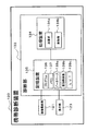
<状況診断システムの概略構成>
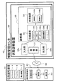
図1において示すように、この状態診断システムは、主として空気調和装置10と、携帯電話端末20と、情報管理センタ40とを備えている。このうち、携帯電話端末20と情報管理センタ40とは、無線回線50を介して通信を行う。
<空気調和装置の構成>
空気調和装置10は、図示しない室内機と室外機等とから構成されており、エアフィルタ5や、ドレンパン6や、熱交換器7等の空気調和装置10を構成する各種部品を備えている。このうちエアフィルタ5は、空気中の埃や塵を取り除いて空気を清浄化させるものであり、空気調和装置10を運転・使用するにつれて目詰まりが生ずることにより、汚染が進行して状態が変化していく。このようにして汚染が進行したエアフィルタ5洗浄されたり、新たなエアフィルタ5と交換されたりする。
<Schematic configuration of the situation diagnosis system>
As shown in FIG. 1, this state diagnosis system mainly includes an
<Configuration of air conditioner>
The
<携帯電話端末の構成>
携帯電話端末20は、主として画像撮影部21と、通信部22と、表示部23とを備えている。
画像撮影部21は、本システムにおける状態診断の対象となるエアフィルタ5の撮影を行う。この画像撮影部21には、自動ピント調節機能、ズーム機能、絞り調整機能、フラッシュ機能、撮影方向調整機能、モノクロ・カラー切り換え機能等の各種機能、レンズ、移動機構等が設けられており、撮影に際しては、エアフィルタ5に対する適した撮影位置にレンズを移動させて撮影を行う。この際、画像撮影部21によって、エアフィルタ5だけでなく指標物体についてもフレームに収まるようにして撮影する。この指標物体は、情報管理センタ40において画像データの処理を行う際に、撮影時のエアフィルタ5に対する位置、距離、角度等の撮影条件に関する撮影条件データを解析するために用いられる。指標物体としては、撮影者が有している物やエアフィルタ5に隣接して配置されている物等であって、情報管理センタ40においても準備可能な物もしくは情報管理センタ40において当該物に関するデータが格納されている物であればよい。例えば、1円玉等を指標物体として採用する場合には、エアフィルタ5に対して一定の位置・向きとなるように条件を定めて1円玉を配置して、エアフィルタ5と1円玉等とがフレームに収まるおようにして撮影を行う。
<Configuration of mobile phone terminal>
The
The
通信部22は、情報管理センタ40に備わる状態診断装置30の通信部31との間で、無線回線50を介して無線通信を行う。ここでの通信では、通信部22が、画像撮影部21が撮影した画像データ等を送信したり、このようなエアフィルタ5に関する処理態様データを受信したりする。
表示部23は、通信部22が受信したデータ等各種表示を行う。例えば、通信部22が受信した処理態様データの内容を表示したりする。
The
The
<情報管理センタの構成>
情報管理センタ40は、状態診断装置30等を備えている。
状態診断装置30は、通信部31と、入力部32aと、診断部33と、出力部32bとを備えている。
通信部31は、無線回線50を介して携帯電話端末20の通信部22と通信を行う。
<Configuration of Information Management Center>
The
The
The
入力部32aは、携帯電話端末20から送られてくる画像データ等を診断部33の記憶装置35に対して入力する。また、図示しないマウスやキーボード等を介してその他の情報を入力することもできる。
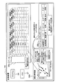
診断部33は、記憶装置35や処理装置34等を備えており、入力部32aによって得られる画像データ等に基づいて、撮影条件データの解析や、エアフィルタ5の状態に対応する処理内容についての処理態様データの作成を行う。記憶装置35は、図2において示すように、プログラム36,メモリ37,データベース38a,重回帰係数38b,LUT38c(ルックアップテーブル)等を備えており、処理装置34は、演算部34aや制御部34b等を備えている。ここで、記憶装置35において入力部32aからの画像データ等が得られると、演算部34aは、記憶装置35からプログラム36を読み出してデータ処理に関するさまざまな演算を行う。具体的には、演算部34aは、画像データを記憶装置35から読み出して、指標物体に基づいて撮影条件データを解析して補正等の処理を施した後に、プログラム36に基づいて後述する二値化処理等の演算処理を実行し、エアフィルタ5の状態情報が数値化された処置番号Yに相当する演算結果を得る。なお、ここでの撮影条件データの解析においては、画像データに含まれている指標物体の向きや大きさ等の情報について、記憶装置における別個のデータベース(図示せず)に格納されている指標物体に関する情報と比較させることで、エアフィルタ5がどのような位置、距離、角度等の撮影条件において撮影されたのかについての情報を、画像データから逆算して求めるという作業が行われる。
The
The
メモリ37には、演算処理時に用いられるデータや、演算結果に関するデータ等が一時的に格納される。
データベース38aには、エアフィルタ5の状態診断に関する知識や経験を十分に有しているベテランのサービスエンジニアが過去に行った多くの診断結果をサンプルとして格納されている。具体的には、図2において示すように、撮影された画像データに基づいて求められる様々な特徴抽出パラメータの数値データがサンプル毎に格納されている。なお、データベース38aでは、サービスエンジニアがエアフィルタ5についての新たな状態診断を行った場合に、その新たなデータについてもサンプルとして格納させて、その内容の充実化を図っている。
The
The database 38a stores, as samples, a number of diagnosis results obtained in the past by experienced service engineers who have sufficient knowledge and experience regarding the state diagnosis of the
重回帰係数38bにおいては、図2において示すように、上述したデータベース38aにおいて格納されている各サンプルについての特徴抽出パラメータ毎に、適切な重み付けの値(重回帰式における係数a0〜a5)が求められ、重回帰式における各特徴抽出パラメータの係数データとして格納されている。ここでの重回帰式は、具体的には、以下に示す数式1のようになる。
In the
(数式1)
Y=a0+a1・X1+a2・X2+a3・X3+a4・X4+a5・X5
ここでは、過去においてベテランのサービスエンジニアが行ってきた処置態様(図2参照)が番号化された値に対して、対応する画像データから得られる特徴値を各サンプルの各特徴抽出パラメータ毎にプロットして、最小二乗法によって切片および各特徴抽出パラメータ毎の係数(a0〜a5)を求めて格納している。なお、ここでは、上述のようにしてデータベース38aにおいて新たにサンプルデータが格納される毎に、もしくは新たなサンプルデータが所定の数だけ追加された時点や所定の時間経過した時点等において、上述の最小二乗法によって、切片および各特徴抽出パラメータ毎の係数(a0〜a5)を更新することができる。
(Formula 1)
Y = a0 + a1, X1 + a2, X2 + a3, X3 + a4, X4 + a5, X5
Here, the feature values obtained from the corresponding image data are plotted for each feature extraction parameter of each sample with respect to the values obtained by numbering the treatment modes (see FIG. 2) that have been performed by experienced service engineers in the past. Then, the coefficient (a0 to a5) for each intercept and each feature extraction parameter is obtained and stored by the method of least squares. Here, every time sample data is newly stored in the database 38a as described above, or when a predetermined number of new sample data is added or when a predetermined time has passed, the above-mentioned The coefficients (a0 to a5) for each intercept and each feature extraction parameter can be updated by the method of least squares.
LUT38c(ルックアップテーブル)は、上述のベテランのサービスエンジニアが過去に行った多くの診断結果に基づいて、実際に施された処置態様の種類に対応させて、その際の処置番号Yの値に対して所定の閾値を設けて、処置態様毎に識別可能にしたデータが格納されている(図2参照)。
演算部34aは、重回帰係数38bを参照して得られる重回帰式に、撮影された画像データから得られる情報を入力して、処置番号Yを算出する。そして、LUT38cを参照することで、この処置番号Yに対して最も良く対応する処理態様データを特定する。ここでの処理態様データは、具体的には、図2において示すように、「処置不要」や「交換」等のテキストデータ等からなるものである。
The
The calculation unit 34a calculates the treatment number Y by inputting information obtained from the captured image data to the multiple regression equation obtained by referring to the
制御部34bは、プログラム36の指示に従って、演算部34aにおいて特定された処理態様データを記憶装置35に送る。この他に、制御部34bは、プログラム36の指示に従って、記憶装置35に、処理態様データを出力部32bまで送信させたり、さらに通信部31まで送信させたりする等の制御を行う。
出力部32bは、記憶装置35から送られてきた処理態様データ等の出力を行う。例えば、情報管理センタ40において、エアフィルタ5の処理態様データを把握できるように、状態診断装置30の図示しないディスプレイ等において表示させたりする。また、出力部32bは、通信部31によって、無線回線50を介して携帯電話端末20に対して処理態様データを送信する。
The control unit 34 b sends the processing mode data specified by the calculation unit 34 a to the
The
<状態診断動作>
まず、情報管理センタ40において所定の時間間隔によって定期的に、あるいは、現地におけるユーザやサービスエンジニア等による状態診断の要求があった場合等に、状態診断装置30の通信部31と携帯電話端末20の通信部22とが無線回線50を介して通信を行い、状態診断装置30は、携帯電話端末20の画像撮影部21によって撮影されるエアフィルタ5の画像データ等を取得する。ここでの画像撮影部21による撮影では、通常、あらかじめ定められた撮影位置、角度、距離に従って、エアフィルタ5と上述の指標物体とが共に撮影される。
<Status diagnosis operation>
First, the
状態診断装置30では、受信したエアフィルタ5についての画像データ等を記憶装置35に格納する。
記憶装置35において画像データ等が得られると、画像データのうちの指標物体の様子をもとに撮影条件データを解析し、演算部34aによってプログラム36が実行されることで、エアフィルタ5の状態情報を数値化し処置番号Yを算出する。そして、演算部34aは、LUT38cを参照して、算出された処置番号Yに最も対応する処置番号によって処理態様データの特定を行う。
In the
When image data or the like is obtained in the
処理態様データは、制御部34bによって、記憶装置35に格納される。
そして、処理態様データは、出力部32bによって出力され、通信部31によって携帯電話端末20の通信部22に対して送信される。
処理態様データを受信した携帯電話端末20は、表示部23によって処理態様データの内容を表示して、エアフィルタ5が設置されている現地のユーザやサービスエンジニア等にエアフィルタ5に対して施すべき処理内容を了知させる。
The processing mode data is stored in the
Then, the processing mode data is output by the
The
<プログラムによる画像データ処理の流れ>
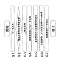
図3において、演算部34aにおいて、プログラム36に従って行われる演算処理の流れをフローチャートで示す。
図3に示すステップS1では、演算部34aが、記憶装置35に格納されている画像データおよび指標物体に関する情報や、プログラム36を読み込む。
<Flow of image data processing by program>
In FIG. 3, the flow of calculation processing performed in accordance with the
In step S <b> 1 shown in FIG. 3, the calculation unit 34 a reads the image data and information on the index object stored in the
図3に示すステップS2では、演算部34aにおいてプログラム36が実行されることによって、撮影条件データの解析を行い、画像データを構成している各画素について補正の必要性を判断して、必要な場合にのみ補正処理を行う。ここでの補正処理では、撮影時における画像撮影部21のエアフィルタ5に対する位置、距離、角度等の情報(解析された撮影条件データ)に基づいて、画像データを処理し易い所定の画像データに修正する処理を行う。
In step S2 shown in FIG. 3, the calculation unit 34a executes the
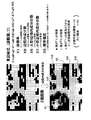
図3に示すステップS3では、演算部34aにおいてプログラム36が実行されることによって、画像データを構成している複数の画素それぞれに対して二値化処理が施される。ここでの二値化処理とは、所定の明度閾値を基準として定めて、それぞれの画素が有している明度に応じて、各画素に対して「0」か「1」のいずれかの値を割り当てる。これにより、図4において示すように、携帯電話端末20の画像撮影部21によって取得された画像データから、二値化画像データが作成される。ここでは、「1」の値が割り当てられた画素を「黒」で表し、「0」の値が割り当てられた画素を「白」として表した画像が作成される。ここでの所定の明度閾値は、撮影するエアフィルタ5の種類や空気調和装置10の機種に応じて、ベテランのサービスエンジニアが蓄積した診断結果のデータに基づいて経験的に定められる。
In step S3 shown in FIG. 3, a binarization process is performed on each of a plurality of pixels constituting the image data by executing the
図3に示すステップS4では、ステップS3で作成された二値化画像データをについて、5つの観点から捕らえた特徴に関するパラメータの値を抽出する特徴抽出処理を行う。すなわち、ここでは、二値化画像データについて定量化を行うことで、エアフィルタ5の状態に関する特徴の抽出が行われていることになる。具体的には、ここでは、以下に示すX1からX5までの5つのパラメータによって表される特徴を抽出する。ここでの特徴抽出処理について、図4を用いて、各パラメータの捉え方を説明する。
In step S4 shown in FIG. 3, feature extraction processing is performed to extract parameter values relating to features captured from five viewpoints with respect to the binarized image data created in step S3. That is, here, the feature relating to the state of the
X1は、面積率を示すパラメータである。ここで、面積率とは、二値化画像の全画素数に対する「1」の値が割り当てられた(黒で表示される)画素の数の割合のことをいう。
X2は、連結成分数を示すパラメータである。ここで、連結成分とは、「1」の値が割り当てられている画素が互いに連結して存在しているもののうち、連結成分閾値よりも多い数の画素数を有している固まりのことをいう。図4においては、連結成分閾値が10の場合を例として挙げている。すなわち、この場合には、「1」の値が割り当てられている画素が10個以上連結されている成分でなければ、連結成分とならない。なお、連結成分閾値は、エアフィルタ5の格子間隔等に基づく等して、エアフィルタ5の種類毎の性質、画像撮影条件、ベテランのサービスエンジニアが蓄積した診断結果のデータ等によって経験的に定められる。ここでの診断対象であるエアフィルタ5の格子間隔は、水平方向の格子間が垂直方向の格子間に比べて長くなっており、連結成分閾値は、このうちの短い方に相当する垂直方向の格子間に基づいて定められている。
X1 is a parameter indicating the area ratio. Here, the area ratio means the ratio of the number of pixels to which the value “1” is assigned (displayed in black) with respect to the total number of pixels of the binarized image.
X2 is a parameter indicating the number of connected components. Here, the connected component refers to a cluster having a number of pixels larger than the connected component threshold among pixels in which pixels assigned the value of “1” are connected to each other. Say. In FIG. 4, a case where the connected component threshold is 10 is taken as an example. That is, in this case, a connected component is not used unless it is a component in which 10 or more pixels to which the value “1” is assigned are connected. The connected component threshold value is determined empirically based on the characteristics of each type of
X3は、大型連結成分ALの数についてのパラメータである。大型連結成分ALとは、図4において示すように、上述した連結成分のうち大小閾値以上の画素数を有する連結成分のことをいう。図4においては、大小閾値が30の場合を例として挙げている。すなわち、この場合には、「1」の値が割り当てられている画素が30個以上連結されている連結成分でなければ、大型連結成分とならない。ここで大小閾値についても、例えばエアフィルタ5の格子間距離のうち短い方に当たる垂直方向の格子間距離等に応じる等して、エアフィルタ5の種類毎の性質、画像撮影条件、ベテランのサービスエンジニアが蓄積した診断結果のデータによって経験的に得られるデータ等に基づいて定められる。
X3 is a parameter for the number of large connected components AL. As shown in FIG. 4, the large connected component AL refers to a connected component having the number of pixels greater than or equal to the threshold value among the above-described connected components. In FIG. 4, the case where the magnitude threshold is 30 is taken as an example. That is, in this case, the connected component is not a large connected component unless it is a connected component in which 30 or more pixels to which the value “1” is assigned are connected. Here, with respect to the large and small thresholds, for example, depending on the vertical inter-lattice distance corresponding to the shorter one of the inter-lattice distances of the
X4は、小型連結成分ASの数についてのパラメータである。小型連結成分ASとは、図4において示すように、上述した連結成分のうち大小閾値に満たない画素数を有する連結成分のことをいう。
X5は、標準偏差についてのパラメータである。すなわち、二値化画像の全体における値が「1」の画素の分布の偏り度合いについての指標となるパラメータである。ここでは、図4において示すように、二値化画像をC1、C2、C3、C4の4つに分割した場合を例に挙げている。具体的には、ここでのX5の算出においては、まず、各分割連結成分におけるC1、C2、C3、C4に含まれる画素数が150画素で互いに等しくなるように均等に分割し、分割連結成分毎の画素数を求め、この画素数についての平均値を算出する。次に、この平均値と分割連結成分における画素数との差を二乗した値を、分割連結成分毎に求め、これらを合計する。そして、この合計値を、分割した連結成分の数である4で除して、得られる値の平方根を算出する。この値がX5として算出される値となる。ここで、標準偏差が小さい場合には、画像全体における「1」の値が割り当てられた画素の分布の偏り度合いが小さいことを示す。逆に、標準偏差が大きい場合には、画像全体における「1」の値が割り当てられた画素の分布の偏り度合いが大きいことを示す。
X4 is a parameter for the number of small connected components AS. As shown in FIG. 4, the small connected component AS refers to a connected component having the number of pixels less than the threshold value among the above-described connected components.
X5 is a parameter for standard deviation. That is, it is a parameter that serves as an index for the degree of bias in the distribution of pixels with a value of “1” in the entire binarized image. Here, as shown in FIG. 4, a case where the binarized image is divided into four parts C1, C2, C3, and C4 is taken as an example. Specifically, in the calculation of X5 here, first, the divided connected components are divided equally so that the number of pixels included in C1, C2, C3, and C4 in each divided connected component is equal to 150 pixels. The number of pixels for each pixel is obtained, and an average value for this number of pixels is calculated. Next, a value obtained by squaring the difference between the average value and the number of pixels in the divided connected component is obtained for each divided connected component, and these are summed. Then, the total value is divided by 4 which is the number of divided connected components, and the square root of the obtained value is calculated. This value is a value calculated as X5. Here, when the standard deviation is small, it indicates that the degree of bias of the distribution of the pixels assigned the value “1” in the entire image is small. Conversely, when the standard deviation is large, it indicates that the degree of bias of the distribution of the pixels assigned the value “1” in the entire image is large.
図3に示すステップS5では、ステップS4で抽出された各パラメータX1からX5について、重み付けを施すために上述した重回帰式に代入する。この重み付けを施す重回帰式における各特徴抽出パラメータに割り当てられる係数および切片(a0〜a5)は、エアフィルタ5の状態診断に関する知識や経験を十分に有するベテランのサービスエンジニアが行った過去の多くの診断結果をサンプルとして、上述のように最小二乗法によって算出されることで得られる値である。この重回帰式に対して、ステップS4で特徴抽出された各パラメータの値を代入することで、処理番号Yの値が算出される。
In step S5 shown in FIG. 3, the parameters X1 to X5 extracted in step S4 are substituted into the above-described multiple regression equation for weighting. The coefficients and intercepts (a0 to a5) assigned to each feature extraction parameter in the multiple regression equation to which this weighting is applied are many of the past conducted by veteran service engineers who have sufficient knowledge and experience regarding the state diagnosis of the
図3に示すステップS6では、ステップS5において得られた処置番号Yを、LUT38cに格納されている処置番号Yと対比して最も対応する処置番号を特定して、エアフィルタ5の処理態様データを特定し、状態データを確認する。ここでの処理態様データとは、具体的には、「処置不要」や「交換」等の情報を示すテキストデータ等である。また、ここで確認された状態データは、診断を行う毎にデータベース38aにおいて随時格納されていく。
In step S6 shown in FIG. 3, the treatment number Y obtained in step S5 is compared with the treatment number Y stored in the
図3に示すステップS7では、得られた処理態様データを通信部31によって、携帯電話端末20まで送信させる。
<第1実施形態に関する特徴>
(1)
一般に、空気調和装置に設けられているフィルタは、運転されることにより次第に汚染の度合いが増していく。このようにフィルタの汚染度合いが進行した場合にはメンテナンスを行う必要が生じるが、従来、ユーザやサービスエンジニア等が目視によってフィルタの汚染進行度合い等についての状態判断を行っている。ところが、目視によって状態診断を行っているために、フィルタの汚染進行度合い等について定量化させることが困難である。また、熟練された技術や知識を有するサービスエンジニアによって診断された場合と未熟なサービスエンジニアによって診断された場合とで食い違いが生じる等、一定の基準による安定した診断を行うことが難しく、診断結果は信頼性に欠けたものとなるおそれがある。
In step S <b> 7 shown in FIG. 3, the obtained processing mode data is transmitted to the
<Features of the first embodiment>
(1)
In general, a filter provided in an air conditioner gradually increases the degree of contamination as it is operated. When the degree of contamination of the filter progresses as described above, maintenance is required. Conventionally, however, a user, a service engineer, or the like has made a visual judgment on the degree of contamination of the filter. However, since the state diagnosis is performed visually, it is difficult to quantify the degree of contamination progress of the filter. In addition, there is a discrepancy between when diagnosed by a service engineer with skilled technology and knowledge, and when diagnosed by an inexperienced service engineer. May become unreliable.
これに対して、上記第1実施形態における状態診断システムでは、診断部33が、エアフィルタ5の状態が反映された画像データから二値化画像を作成して、経験的に定められる重回帰式により処置態様を機械的に定めることで状態診断を行う。このため、統一された判断手法に沿ってエアフィルタ5の状態診断を行うことができ、エアフィルタ5のユーザやサービスエンジニア等の個人的な主観による判断が含まれることを抑えて、状態診断における信頼性を向上させることができる。
On the other hand, in the state diagnosis system according to the first embodiment, the
また、連結成分閾値や大小閾値についても、エアフィルタ5の種類毎の性質、画像撮影条件、ベテランのサービスエンジニアが蓄積した診断結果によって経験的に得られるデータ等に基づいて定められている。このため、重回帰式において反映されるパラメータにおいてエアフィルタ5の状態等をより反映させることができ、診断結果の信頼性をより向上させることができるようになる。
The connected component threshold value and the magnitude threshold value are also determined based on the characteristics of each type of the
(2)
また、現地のユーザやサービスエンジニアは、携帯電話端末20によって画像を取得して情報管理センタ40に対して送信するという簡易な動作を行うだけで、ベテランのサービスエンジニアによる多くの診断結果が反映された処置態様データを得ることができ、自動的で簡易且つ迅速に処置態様を把握することができる。このため、ユーザやサービスエンジニア等のメンテナンス作業時間のうち、判断に要する時間を短縮化させることができる。すなわち、現地のユーザやサービスエンジニアは、エアフィルタ5の状態を把握できた場合であっても、その状態に対して施すべき具体的な処置態様が分からなかったり迷ったりすることがある。このような場合でも、上記システムによって自動的で簡易且つ迅速に処置態様を把握することができる。また、サービスエンジニアが現地へ出動する前に、異常原因や必要部品(取替え部品等)の処置態様についてのデータを把握することが可能になるため、出動を要するようなメンテナンスを行う場合において、必要な部品を初めから用意していくことができる。このため、1回の出動によって、もしくは少ない出動回数によって、効果的にメンテナンスを終了させることができるようになり、修理部品を持ち合わせていないために再度の出動が必要となる等の無駄な作業時間を削減して、メンテナンスの効率を向上させることができる。さらに、サービスエンジニアの出動を効率化させることで、サービスエンジニアの必要人員数を少なく抑えることにより人件費の削減化も可能になり、メンテナンスコストの低減化を図ることができる。
(2)
Moreover, a local user or a service engineer simply performs a simple operation of acquiring an image by the
また、エアフィルタ5の状態診断を高い信頼性を維持しながら行うためには、所定の経験を積んだベテランのサービスエンジニアが必要となったり人材育成に時間が掛かったりする等人件費がかさむ場合があるが、上記第1状態診断システムによると、携帯電話端末20によって取得した画像データを情報管理センタ40に対する送信するだけで自動的に高信頼性の処置態様データが得られるために、ベテランのサービスエンジニアを情報管理センタ40に常に待機させておく等の必要が無くなり、この点においても人件費を削減できる。また、現地に出動させるサービスエンジニアの資質についても、熟練された技術や知識を有している必要が無くなり、十分な知識を有していないサービスエンジニアであっても容易にベテランのエンジニアのような的確な処置態様を行うことができるようになり、サービスエンジニアの資質についての制限を低くすることも可能となる。また、サービスエンジニアを現地に出向かせる場合であっても、エアフィルタ5の汚れ状態に対する処置サンプル等の資料を持ち歩く必要が無くなる。
In addition, in order to carry out the state diagnosis of the
(3)
また、エアフィルタ5を撮影して得られた各画像データにおいて、汚れがひどく見える部分やほとんど汚れていないように見える部分等、汚れている部分や程度にはばらつきが生じていることがあるが、撮影された画像データを全体的に処理するのであれば、このような汚れのばらつき等が考慮されないままの診断となってしまう。
(3)
Further, in each image data obtained by photographing the
これに対して、上記第1実施形態における状態診断システムでは、エアフィルタ5の画像データから特徴抽出して得られるパラメータによって、同じ値が割り当てられている画素の固まりである連結成分についての情報が反映され、分割成分を参照することで汚染状態のばらつきについても反映させた状態診断を行っている。すなわち、重回帰式においては、大型連結成分AL、小型連結成分AS、分割連結成分C1、C2、C3、C4に関するデータがパラメータとして含まれている。これにより、汚れのばらつき等についても考慮しつつ参照データの偏りを抑えた診断が可能となり、診断における信頼性をより向上させている。
On the other hand, in the state diagnosis system according to the first embodiment, information on the connected component, which is a cluster of pixels to which the same value is assigned, is obtained by a parameter obtained by extracting features from the image data of the
(4)
エアフィルタ5の画像診断において二値化された画像から特徴を抽出するに際して、独立して存在する小さな画像成分は誤差の原因となることがある。
これに対して、上記第1実施形態に係る状態診断システムにおいては、連結成分数が連結成分閾値を越えているようなある程度大きな成分を特化させて重回帰式に反映しており、連結成分に含まれる画素数が連結成分閾値を越えないような連結成分についてはあまり重回帰式に反映されていない。これにより、エアフィルタ5の状態診断において、誤差の原因となるようなデータの影響を抑えて、状態診断における信頼性を向上させている。
(4)
When extracting a feature from a binarized image in the image diagnosis of the
On the other hand, in the state diagnosis system according to the first embodiment, a certain large component such that the number of connected components exceeds the connected component threshold value is specialized and reflected in the multiple regression equation. The connected components that do not exceed the connected component threshold are not reflected in the multiple regression equation. Thereby, in the state diagnosis of the
<第1実施形態の変形例>
以上、本発明の一実施形態について説明したが、本発明は上記実施形態に限定されるものではなく、発明の要旨を逸脱しない範囲で種々の変更が可能である。
(A)
上述した第1実施形態では、重回帰式における特徴抽出パラメータの一つとして、同じ値が割り当てられて隣接して存在する画素から連結成分が構成されており、離れている画素は同じ連結成分には含まれないとする概念を用いている。
<Modification of First Embodiment>
As mentioned above, although one Embodiment of this invention was described, this invention is not limited to the said embodiment, A various change is possible in the range which does not deviate from the summary of invention.
(A)
In the first embodiment described above, as one of the feature extraction parameters in the multiple regression equation, the same value is assigned and a connected component is composed of adjacent pixels, and distant pixels are changed to the same connected component. The concept that is not included is used.
これに対して、上記発明は連結成分の概念に限られるものではなく、離れて存在する画素であっても割り当てられた値が同じであって所定の近傍距離の範囲内に存在する画素同士であれば同じ成分に含まれるという概念を用いてもよい。
また、例えば、図5において示すように、異なる値が割り当てられている画素であっても、「0」の値が割り当てられている画素が、2つ以上の「1」の値の画素であって同一連結成分に属するものそれぞれに対して所定の近傍距離内に配置されているという条件を満たしている場合には、その「0」の値の画素は、「1」の値の画素から成る連結成分に含めるとして画素数をカウントする近傍内連結成分の概念を用いてもよい。
On the other hand, the above invention is not limited to the concept of connected components, and even if the pixels exist at a distance, the assigned values are the same and the pixels existing within a predetermined neighborhood distance range You may use the concept of being contained in the same component if it exists.
Further, for example, as shown in FIG. 5, even if a pixel is assigned a different value, a pixel assigned a value of “0” is two or more pixels having a value of “1”. The pixels having the value “0” are composed of the pixels having the value “1”. You may use the concept of the connection component in a neighborhood which counts the number of pixels as including in a connection component.
なお、上述した所定の近傍距離としては、いわゆるユークリッド距離、4−近傍距離、8−近傍距離、8角形距離等いずれを基準としてもよい。
また、二値化画像中における近傍内成分としては、例えば、図5において示すように、「0」の値の画素についても、2つ以上の「1」の値の画素であって同一連結成分に属するものそれぞれに対して所定の4−近傍距離(=1)内に配置されているという条件を満たせばカウントするとしたうえで、所定の近傍内成分閾値(=15)と、所定の大小閾値(=30)とによって、近傍内大型成分NLと、近傍内小型成分NSとに分けられる。
The predetermined neighborhood distance described above may be based on any of so-called Euclidean distance, 4-neighbor distance, 8-neighbor distance, octagonal distance, and the like.
In addition, as an in-neighbor component in the binarized image, for example, as shown in FIG. 5, a pixel having a value of “0” is two or more pixels having a value of “1” and the same connected component. Are counted if the condition that they are arranged within a predetermined 4-neighbor distance (= 1) is satisfied for each of those belonging to the group, a predetermined near-component threshold (= 15), and a predetermined magnitude threshold (= 30), it is divided into a near-inner large component NL and a near-inside small component NS.
この場合には、重回帰式は以下に示すようになる。
(数式2)
Y=a0+a8・X8+a2・X2+a6・X6+a7・X7+a5・X5
ここで、X6は近傍大型成分の数を、X7は近傍小型成分の数を示す。また、X8は、近傍内成分の数を示す。他の演算処置については、上述した第1実施形態における状態診断システムと同様である。
In this case, the multiple regression equation is as follows.
(Formula 2)
Y = a0 + a8.X8 + a2.X2 + a6.X6 + a7.X7 + a5.X5
Here, X6 indicates the number of nearby large components, and X7 indicates the number of nearby small components. X8 indicates the number of components in the vicinity. Other arithmetic processing is the same as the state diagnosis system in the first embodiment described above.
このように、エアフィルタ5の二値化画像における連結成分について、マクロな視点によって把握される概略を重回帰式において反映させることが可能になる。これにより、エアフィルタ5の状態についての概略を診断において反映させることが可能になる。
(B)
上述した第1実施形態では、画像データに対して1回の二値化処理が施されて得られる二値化画像に基づいて特徴抽出を行っているが、画像データに対する二値化処理は1回に限られる必要はない。
As described above, the outline obtained from the macro viewpoint can be reflected in the multiple regression equation for the connected component in the binarized image of the
(B)
In the first embodiment described above, feature extraction is performed based on a binarized image obtained by performing binarization processing once on image data. However, binarization processing on image data is 1 There is no need to be limited to times.
例えば、1回目の二値化処理によって含まれる画素数が第1閾値に達していない成分中画素を「A」として、第1閾値に達している成分中の画素に対しては2回目の二値化処理を施す。そして、2回目の二値化処理が施された場合に、第2閾値に達していない成分中の画素を「B」として、第2閾値に達している成分中の画素に対しては3回目の二値化処理を施す。そして、3回目の二値化処理が施された場合に、第3閾値に達していない成分中の画素を「C」として、第3閾値に達している成分中の画素を「D」とする等、多段階的にラベルに割り当てるラベリング処理を行い、重回帰式に反映させるパラメータをより詳細なものにしてもよい。 For example, the pixel in the component in which the number of pixels included in the first binarization process does not reach the first threshold value is “A”, and the pixel in the component in which the first threshold value is reached is “2” for the second time. Apply value processing. Then, when the second binarization process is performed, the pixel in the component that has not reached the second threshold is set to “B”, and the pixel in the component that has reached the second threshold is the third time. The binarization process is performed. Then, when the third binarization process is performed, the pixel in the component that has not reached the third threshold is set to “C”, and the pixel in the component that has reached the third threshold is set to “D”. For example, the labeling process assigned to the label in multiple steps may be performed, and the parameters reflected in the multiple regression equation may be made more detailed.
すなわち、各成分に含まれる画素数の多さに応じてA、B、C、D等ラベリングを行い、各ラベルが付されている成分毎に異なる重み付けを施して、重回帰式に反映させてもよい。
また、連結成分閾値や大小閾値について、例えば、二値化画像全体のうちの所定の特定場所を定めて、その所定の特定場所に属する連結成分に対する連結成分閾値や大小閾値を、他の場所に属する連結成分の画素数に対するものよりも多くしたり少なくしたりして、両者に差を設けてもよい。エアフィルタ5の設置状況やフレームの形状との関係により汚れやすい部分等の特徴がある場合には、その特徴をより的確に抽出することが可能となる。具体的には、二値化画像中のエアフィルタ5のメンテナンスの必要性に関して影響を与えにくい部分については、その部分に属する連結成分に対する連結成分閾値や大小閾値を大きい値に設定する等の方法が考えられる。
In other words, A, B, C, D, etc. are labeled according to the number of pixels included in each component, and different weights are applied to each labeled component to reflect them in the multiple regression equation. Also good.
Further, for the connected component threshold value and the magnitude threshold value, for example, a predetermined specific place in the entire binarized image is determined, and the connected component threshold value and the large and small threshold value for the connected component belonging to the predetermined specific place are set to other places. A difference may be provided between both of them by increasing or decreasing the number of connected components to the number of pixels. If there is a feature such as a portion that tends to become dirty due to the installation condition of the
また、重み付けについても、上述した第1実施形態における重回帰式のように大型連結成分ALの数X3と小型連結成分ASの数X4のみに対して行うのではなく、例えば、二値化画像全体のうちの所定の特別場所を定めて、その所定の特別場所に属する連結成分の数については、他の連結成分の数よりもさらに大きな値もしくは小さな値を乗じる等により、連結成分の属する場所に応じて重み付けに差を設けるようにしてもよい。 Also, weighting is not performed only on the number X3 of large connected components AL and the number X4 of small connected components AS as in the multiple regression equation in the first embodiment described above, for example, the entire binarized image, for example. The number of connected components belonging to the predetermined special location is determined by multiplying the number of connected components belonging to the predetermined special location by a value larger or smaller than the number of other connected components. Accordingly, a difference in weighting may be provided.
(C)
上述した第1実施形態では、状態診断システムにおける診断対象が空気調和装置10に設けられたエアフィルタ5である場合を例に挙げて説明した。しかし、本発明における診断対象はこのようなエアフィルタ5に限られるものではなく、図1において示すように、空気調和装置10の水回りに関するドレンパン6や、熱交換器7等、外観が徐々に変化していく様子が映像によって判断可能な消耗部品等であれば診断対象とすることができる。例えば、使用によって状態が変化したり、劣化したり、色彩が変化したりするようなものでもよい。
(C)
In 1st Embodiment mentioned above, the case where the diagnostic object in a state diagnostic system was the
この場合には、ドレンパン6、熱交換器7についての画像を取得して、上記実施形態における診断と同様にして状態診断することができる。なお、このように、診断対象が異なる場合には、各診断対象の種類に応じてベテランサービスエンジニアのサンプルデータからデータベースを構築して、それぞれの診断において参照できるようにする。なお、水回りの汚れ(ドレンパン汚れ)を定量化する基準としては、例えば診断対象となるドレンパン6の大きさ等をパラメータとする等して経験的に求まる値としたり、熱交換器7の汚れを定量化する基準としては、例えばクロスフィンコイル式の熱交換器の場合においてはプレートフィンが設けられている間隔等をパラメータとする等して経験的に求まる値としてりしてもよい。
In this case, images of the
(D)
上述した第1実施形態の二値化処理においては、各画素が有している明度に基づいて明度閾値を基準にして処理が行われている。しかし、二値化処理の基準としては明度に限られるものではなく、鮮度や色相等についても基準とすることができる。また、これら明度や、鮮度、色相を総合評価して二値化処理を行うようにしてもよい。画像データがカラー画像の場合には、これら鮮度、色相等について状態診断におけるパラメータついて反映させることができ、より詳細な状態診断を行うことが可能になる。
(D)
In the binarization process of the first embodiment described above, the process is performed based on the brightness threshold based on the brightness of each pixel. However, the criterion for the binarization process is not limited to lightness, and it can also be a criterion for freshness, hue, and the like. Further, binarization processing may be performed by comprehensively evaluating the brightness, freshness, and hue. When the image data is a color image, the freshness, hue, and the like can be reflected on parameters in the state diagnosis, and a more detailed state diagnosis can be performed.
(E)
上述した第1実施形態では、空気調和装置10に設けられているエアフィルタ5についての状態診断において、携帯電話端末20の画像撮影部21によって撮影された画像データが状態診断装置30へ送信されて、データベース38aに格納されている。
これに対して、エアフィルタ5の画像を定期的に撮影して診断を行う場合等には、診断を行う毎に得られるエアフィルタ5の画像データや処置態様データをデータベース38aに蓄積させていくようにしてもよい。この場合には、後に画像データを取得して診断する場合に、前回の画像データと比較して視覚的変化が著しい部分のデータや前回の診断からの経過時間等をデータ特徴抽出パラメータとして採用することもできるようになり、より対象の性質に見合った診断を行うことができるようになる。
(E)
In the first embodiment described above, in the state diagnosis of the
On the other hand, when the diagnosis is performed by periodically taking an image of the
なお、このように定期的に撮影を行うことで一つのエアフィルタ5に対して複数回繰り返して状態診断を行う場合には、診断回数が増えるにしたがって、データベース38aに格納される情報を充実化させることができ、汚染や劣化の進行度合いについて機種毎に異なる特徴を把握することができる場合がある。この場合には、機種毎の情報を把握して、連結成分閾値や大小閾値等を、当該機種に見合ったより適切な閾値に設定変更や更新を行うようにしてもよい。例えば、エアフィルタ5の吸い込み口側において所定の網目形状のパネルが設けられている場合には、エアフィルタ5の当該パネルの所定の網目の隙間に対応する部分の汚染進行速度が他の部分よりも速くなりがちになることがある。このような場合には、たとえ他の部分の汚染進行程度が低い場合であっても、当該パネルの所定の網目の隙間に対応する位置の汚染が進行してしまうと、フィルタとして有効に機能を発揮する部分がその機能を十分に発揮できないことになり、空気調和装置10の運転負担が増加する等の問題が生じてしまう。このため、診断対象のエアフィルタ5について、汚染進行速度が速い部分についての二値化画像のデータについて重み付けを増したり、汚染進行速度が遅い部分についての二値化画像のデータについて重み付けを減少させたりすることで、状態診断をより適切に行うことが可能になる。
In addition, when the state diagnosis is repeated a plurality of times for one
また、前回の診断からの時間経過を参照することでユーザ毎の使用頻度情報についても把握可能であるため、例えば、前回の状態から汚染進行度合いが少ない場合(処置番号Yの増加分が少ない場合)には、エアフィルタ5の交換は2ヶ月程度先でもよい等の付加情報についても把握することができるようになる。
また、定期的にもしくは常時エアフィルタ5の画像データを取得する場合には、例えば、二値化処理や重回帰式によって得られる値によって、エアフィルタ5の汚れが所定の汚染度合いを超えているか否かを判断して、所定の汚染度合いを越えた時点で携帯電話端末20の表示部23にその旨を報知するようにしてもよい。これにより、メンテナンスが必要となるタイミングを容易に把握することができる。また、汚染度合いが進んだエアフィルタ5について洗浄処理や交換処理を施す場合には、定期的にもしくは常時エアフィルタ5の洗浄中や洗浄後または交換後における画像データを取得して二値化処理や重回帰式によって得られる値によって、メンテナンスが終了したか否かを判断して、メンテナンスが終了した時点でその旨を報知することができるようにしてもよい。なお、同様に洗浄処理や交換処理が終了した際に、完了した旨を報知できるような構成にしてもよい。
In addition, since it is possible to grasp the usage frequency information for each user by referring to the passage of time since the previous diagnosis, for example, when the degree of contamination progress is small since the previous state (when the increase in the treatment number Y is small) ), It is possible to grasp additional information such that the replacement of the
In addition, when acquiring image data of the
(F)
上述した第1実施形態では、携帯電話端末20の画像撮影部21を用いて各ユーザやサービスエンジニア等が現地で撮影した画像データに対して、情報管理センタ40の状態診断装置30において二値化処理を施している。
これに対して、画像処理機能および通信機器を備えている携帯電話端末20や他の通信装置によって、エアフィルタ5の撮影をする際に、画像データそのままを送信するのではなく、現地で先に二値化処理を施して情報管理センタ40に対して送信するようにしてもよい。この場合には、情報管理センタ40の状態診断装置30における二値化処理を省略することができる。また、撮影されたそのままの画像データを送信する場合と比較して通信データ量を少なくすることができる。また、これにともない、通信速度を向上させて、より迅速なメンテナンスを行うことも可能になる。
(F)
In the first embodiment described above, the image data captured by each user, service engineer, or the like using the
On the other hand, when the
(G)
上述した第1実施形態における状態診断装置30の診断対象が、空気中の非常に微細な粒子を取り除いたり臭気成分を低減(脱臭)したり除菌したりすることが可能なもの(例えば、活性炭や、脱臭フィルタ等)である場合や、その他の非常に微細構造を有する診断対象である場合には、画像撮影部21においてミクロンオーダー等での微細構造や微細部分の観察が可能な顕微鏡等を設けて、診断対象の表面にピントを合わせて撮影させることもできる。この場合には、熟練されたベテランのサービスエンジニアであっても微妙な判断が要求され判断が困難な場合であっても、診断部33に状態診断させることができる。
(G)
The diagnosis target of the
(H)
上述した第1実施形態では、現地のサービスエンジニアは、携帯電話端末20に送られてくる処置態様データに基づいてエアフィルタ5の処置を行っている。これに対して、現地のサービスエンジニアが状態診断データの最終確認を行うことができるようにするため、処置態様データだけでなく他のデータ(処置番号Y付近の処置態様データ等の内容も含めたデータ等)を送信するようにしてもよい。これにより、現地のサービスエンジニアは、得られたデータの最終確認を行うことができる。この場合には、サービスエンジニアが、自ら最終確認を行うことにより処置態様を必要に応じて訂正することも可能になり、システム全体における信頼性を向上させることができるようになる。
(H)
In the first embodiment described above, the local service engineer performs the treatment of the
(I)
上述した第1実施形態におけるデータベース38aは、状態診断装置30の内部に設けられているが、これらとは別個独立した場所や、情報管理センタ40とは別の場所に設けられていてもよい。また、上記第1実施形態では、情報管理センタ40と携帯電話端末20とは、無線回線50を介して通信を行っているが、有線を介することにより通信を行うものであってもよい。また、記録媒体を介して、現地と情報管理センタ40との間で情報のやり取りを行うようにしてもよい。
(I)
Although the database 38a in the first embodiment described above is provided in the
(J)
上述した第1実施形態における重回帰式では、処置番号Yを算出するための特徴抽出パラメータがX1からX5までの5つの場合を例に挙げて説明したが、ここでのパラメータとしては、5つ以上であってもよいし、5つより少ない場合であってもよい。
また、他の特徴抽出パラメータとしては、空気調和装置10の使用状況等を採用してもよい。例えば、運転時間と汚染の進行との間の相関を考慮して、空気調和装置10の積算運転時間や1日の平均運転時間等を特徴抽出パラメータとして採用するようにしてもよい。また、埃の濃度レベル等の検知が可能な空気調和装置であれば、埃の濃度に関する値を特徴抽出パラメータとして採用するようにしてもよい。この他、技術内容を熟知しているベテランのサービスエンジニアの診断において判断基準とされているような特徴が抽出されたパラメータであればよい。
(J)
In the multiple regression equation in the first embodiment described above, five feature extraction parameters for calculating the treatment number Y have been described by way of example, but there are five parameters as parameters here. The above may be sufficient, and the case where it is less than five may be sufficient.
Moreover, you may employ | adopt the usage condition etc. of the
また、データベース38aにおいて格納されている処置番号に対応する処置態様データについても、図2において示した4段階には限られず、より多くの段階に分けて示されている場合でも、より少ない段階に分けて示されている場合でもよい。
(K)
上述した第1実施形態におけるエアフィルタ5の撮影条件データの解析においては、エアフィルタ5と指標物体との両方がフレームに収まるように撮影を行い、情報管理センタ40に共通の指標物体に関する情報を持たせておく等によって、撮影条件データの解析を可能にしている。
Further, the treatment mode data corresponding to the treatment number stored in the database 38a is not limited to the four stages shown in FIG. 2, and even if it is divided into a larger number of stages, the number of stages is smaller. It may be shown separately.
(K)
In the analysis of the imaging condition data of the
これに対して、情報管理センタ40において、機種毎のエアフィルタ5に関する情報を格納させておき、サービスエンジニアが、携帯電話端末20から情報管理センタ40に対して画像データの送信を行う際に、撮影したエアフィルタ5が設置されている空気調和装置10の機種名や機番等の機器に固有の情報についても共に送信するようにしてもよい。この場合には、機種毎にエアフィルタ5のサイズや形状等が定められている場合には、画像データの補正においてこのようなデータを参照することで、より信頼性の高い状態診断を簡易な方法で行うことが可能になる。
On the other hand, when the
また、サービスエンジニアがエアフィルタ5の撮影を行う場合には、その撮影方法をあらかじめ定めて教育・訓練しておくことで、一定の撮影条件が保たれるようにしてもよい。また、このような撮影方法をあらかじめ複数種類定めておいてもよく、その場合には、撮影を行ったサービスエンジニアが自ら採用した撮影方法を特定させる情報、例えば、撮影方法Aで撮影した撮影データである旨や、撮影方法Bで撮影した撮影データである旨の情報について、画像データの送信と共に送信するようにしてもよい。この場合には、サービスエンジニアとしては、撮影方法に関する教育・訓練を受けた者であればよいため、その他の知識・経験等を有する熟練したサービスエンジニアを出向させる必要がなく、この点からも人件費を低減させることができる。
Further, when the service engineer performs shooting of the
[第2実施形態]
本発明の第2実施形態に係る携帯診断装置120のブロック概略構成図を図6に示す。ここに示す携帯診断装置120は、主として空気調和装置のエアフィルタの状態診断を行い、その診断結果に対する処理態様をサービスエンジニアに対して報知させるための装置である。
[Second Embodiment]
The block schematic block diagram of the portable
<携帯診断装置の概略構成>
携帯診断装置120は、主として画像撮影部121と、表示部123と、診断部133とを備えている。
画像撮影部121は、状態診断の対象となるエアフィルタを撮影する。この画像撮影部121には、自動ピント調節機能、ズーム機能、絞り調整機能、フラッシュ機能、撮影方向調整機能、モノクロ・カラー切り換え機能等の各種機能、レンズ、移動機構等が設けられており、撮影に際しては、エアフィルタに対する適した撮影位置にレンズを移動させて撮影を行う。この際、画像撮影部121によって、エアフィルタだけでなく指標物体についてもフレームに収まるようにして撮影する。この指標物体は、診断部133において画像データの処理を行う際において、撮影時のエアフィルタに対する位置、距離、角度等の撮影条件に関する撮影条件データを解析するために用いられる。指標物体としては、撮影者が有している物やエアフィルタに隣接して配置されている物等であって、診断部133において当該物に関するデータが格納されている物であればよい。例えば、1円玉等を指標物体として採用する場合には、エアフィルタに対して一定の位置・向きとなるように条件を定めて1円玉を配置して、撮影を行う。また、取得された画像データ等は、診断部133の記憶装置135に送られる。
<Schematic configuration of portable diagnostic device>
The portable
The
診断部133は、記憶装置135や処理装置134等を備えており、撮影条件データの解析や、画像撮影部121から送られてくるデータの処理を行い、診断結果に基づいて処置態様データを作成する。記憶装置135は、プログラム136や、メモリ137や、データベース138a,重回帰係数138b,LUT138c(ルックアップテーブル)等を備えており、処理装置134は、演算部134aや制御部134b等を備えている。ここで、記憶装置135において画像撮影部121から画像データ等を取得すると、演算部134aは、記憶装置135からプログラム136を読み出してデータ処理に関するさまざまな演算を行う。具体的には、演算部134aは、画像データ等を記憶装置135から読み出して、プログラム136に基づいて二値化処理等の演算を実行し、エアフィルタの状態情報が定量化、数値化された処置番号Yに相当する演算結果を得る。
The
なお、ここでのプログラム136に従った演算は、上述した第1実施形態におけるプログラム36の演算と同様である。また、撮影条件データの解析および画像データの補正についても上述した第1実施形態と同様である。メモリ137には、演算処理時に用いられるデータや、演算結果に関するデータ等が一時的に格納される。なお、データベース138a,重回帰係数138b,LUT138cについては、上記第1実施形態と同様にベテランサービスエンジニアの過去のサンプルデータに基づいて、それぞれ特徴抽出パラメータのデータ,重回帰式の各係数,処置番号Yに対応した処置態様データが格納されている。制御部134bは、プログラム136の指示に従って、特定された処理態様データを記憶装置135に送る。この他に、制御部134bは、プログラム136の指示に従って、処理態様データを記憶装置135に表示部123まで送信させる等の制御を行う。
The calculation according to the program 136 here is the same as the calculation of the
表示部123は、図示しないディスプレイを備えており、記憶装置135において得られた処置態様データをこのディスプレイに表示する等、各種データの表示を行う。
<第2実施形態に関する特徴>
なお、ここでの第2実施形態に係る携帯診断装置120の特徴ついては、上記第1実施形態における状態診断システムにおける特徴として説明した内容であって第2実施形態に係る携帯診断装置120についても同様の特徴については記載を省略する。
The
<Features of Second Embodiment>
Note that the characteristics of the portable
(1)
上記第1実施形態における状態診断システムにおいては、携帯電話端末20から一度情報管理センタ40に対して情報を送信することで、処置態様データを取得している。
これに対して、上記第2実施形態における携帯診断装置120では、画像撮影部121によって取得されるエアフィルタの画像データを、他のセンタや装置等に対して送信することなく、スタンドアロンで状態診断および処置態様データをサービスエンジニアに報知させることが可能になる。これによって、現地サービスエンジニアはより迅速により信頼性の高いデータに基づいてエアフィルタのメンテナンスを行うことができるようになる。
(1)
In the state diagnosis system in the first embodiment, the treatment mode data is acquired by transmitting information from the
On the other hand, in the portable
(2)
上記第2実施形態における携帯診断装置120では、画像データを通信することなく状態診断を行い、処置態様データを作成することができる。このため、通信コストを削減させることができる。また、通信の確立が困難な場所や通信を確立するために専用線の設置が必要となる等設備費用がかさむような場所において診断対象が設けられている場合であっても、上述した第2実施形態における携帯診断装置120では、通信を行う必要がないため、このようなコストを削減することができる。また、このような通信の確立が困難な現地でエアフィルタを撮影した後に、通信可能なエリアまで移動して通信する等の煩雑な動作が不要となる。
(2)
In the portable
<第2実施形態の変形例>
以上、本発明の第2実施形態について説明したが、本発明は上記第2実施形態に限定されるものではなく、発明の要旨を逸脱しない範囲で種々の変更が可能である。なお、上記第1実施形態における状態診断システムの変形例として説明した内容であって、第2実施形態に係る携帯診断装置120に対しても同様に適応可能な例については記載を省略する。
<Modification of Second Embodiment>
Although the second embodiment of the present invention has been described above, the present invention is not limited to the second embodiment, and various modifications can be made without departing from the scope of the invention. Note that the description is omitted as to the contents that have been described as a modified example of the state diagnosis system in the first embodiment and can be similarly applied to the
(A)
上述した第2実施形態に係る携帯診断装置120は、カメラ付き携帯電話端末に内蔵させるようにして、携帯診断装置120の画像撮影部121は、携帯電話端末のカメラ部分を流用させることによって実現させるような構成であってもよい。
(B)
上述した第2実施形態に係る携帯診断装置120のデータベース138a,重回帰係数138b,LUT138c等は、記憶装置135に設けられているが、このようなデータを記録媒体に格納させて随時内容の更新が可能なものを用意して、携帯診断装置120の内部構成を簡素化させ、携帯診断装置120自体を小型化を図ってもよい。
(A)
The mobile
(B)
The database 138a, the multiple regression coefficient 138b, the LUT 138c, and the like of the portable
本発明によれば、画像を用いた診断において信頼性を向上させることができるため、外観の状態が変化する部材の診断を行う状態診断装置、状態診断プログラム、状態診断システムへの適用が特に有用である。 According to the present invention, since reliability can be improved in diagnosis using an image, application to a state diagnosis device, a state diagnosis program, and a state diagnosis system for diagnosing a member whose appearance changes is particularly useful. It is.
5 部材(エアフィルタ)
6 部材(ドレンパン)
7 部材(熱交換器)
10 空気調和装置
20 画像取得装置(携帯電話端末)
30 状態診断装置
31 取得部(通信部)
33 診断部
34 処理器(処理装置)
36 状態診断プログラム(プログラム)
38 データベース
120 携帯診断装置
121 取得部(画像撮影部)
AL 所定のブロック、隣接ブロック、隣接大型ブロック(大型連結成分)
AS 所定のブロック、隣接ブロック、隣接小型ブロック(小型連結成分)
NL 所定のブロック、近傍ブロック、近傍大型ブロック(大型近傍内成分)
NS 所定のブロック、近傍ブロック、近傍小型ブロック(小型近傍内成分)
C1、C2、C3、C4 所定のブロック(分割連結成分)
X1 面積率
X3 データ、隣接大型ブロックの数(大型連結成分の数)
X4 データ、隣接小型ブロックの数(小型連結成分の数)
X5 データ、標準偏差
X6 データ、近傍大型ブロックの数(大型近傍内成分の数)
X7 データ、近傍小型ブロックの数(小型近傍内成分の数)
Y 診断値(処理番号)
5 Member (Air filter)
6 member (drain pan)
7 members (heat exchanger)
10
30
33
36 Diagnosis program (program)
38
AL Predetermined block, adjacent block, adjacent large block (large connected component)
AS Predetermined block, adjacent block, adjacent small block (small connected component)
NL Predetermined block, neighborhood block, neighborhood large block (component in large neighborhood)
NS Predetermined block, neighborhood block, neighborhood small block (component in small neighborhood)
C1, C2, C3, C4 Predetermined blocks (divided and connected components)
X1 area ratio X3 data, number of adjacent large blocks (number of large connected components)
X4 data, number of adjacent small blocks (number of small connected components)
X5 data, standard deviation X6 data, number of nearby large blocks (number of components in large neighborhood)
X7 data, number of nearby small blocks (number of components in small neighborhood)
Y Diagnostic value (Process number)
Claims (15)
前記部材(5,6,7)の画像を取得する取得部(31,121)と、
前記画像の画素に対して2つの値のいずれかを割り当てる二値化処理を施して二値化画像を作成し、前記二値化画像を所定のブロック(NL,NS,AL,AS,C1,C2,C3,C4)に分割し、前記所定のブロック(NL,NS,AL,AS,C1,C2,C3,C4)に関するデータ(X3,X4,X5,X6,X7)を利用して診断値(Y)を求め、前記診断値(Y)に基づいて前記部材(5,6,7)の状態診断を行う診断部(33,133)と、
を備えた状態診断装置(30,120)。 A state diagnosis device (30, 120) for diagnosing members (5, 6, 7) whose appearance changes.
An acquisition unit (31, 121) for acquiring an image of the member (5, 6, 7);
A binarization process for assigning one of two values to pixels of the image is performed to create a binarized image, and the binarized image is stored in a predetermined block (NL, NS, AL, AS, C1, C2, C3, C4) and diagnostic values using data (X3, X4, X5, X6, X7) on the predetermined block (NL, NS, AL, AS, C1, C2, C3, C4) (Y) is obtained, and a diagnosis unit (33, 133) for performing a state diagnosis of the member (5, 6, 7) based on the diagnosis value (Y);
A state diagnosis device (30, 120).
請求項1に記載の状態診断装置(30,120)。 The diagnosis unit (33, 133) includes a neighboring block in which the number of pixels included in the block including pixels having the same value located in the vicinity within a predetermined distance in the binarized image is equal to or greater than the first pixel number ( NL, NS), the number of neighboring large blocks (NL) having a number of pixels equal to or larger than the second number of pixels larger than the first number of pixels (X6), and the number of pixels less than the second number of pixels. The diagnostic value (Y) is obtained based on a value obtained by weighting the number of neighboring small blocks (NS) (X7).
The state diagnosis apparatus (30, 120) according to claim 1.
請求項2に記載の状態診断装置(30,120)。 At least one of the first pixel number and the second pixel number is the property of the member (5, 6, 7), the position at the time of shooting the image, the distance at the time of shooting the image, or the position of the image. Based on the angle at the time of shooting,
The state diagnosis apparatus (30, 120) according to claim 2.
請求項1に記載の状態診断装置(30,120)。 In the binarized image, the diagnosis unit (33, 133) has an adjacent block (AL, AS) in which the number of adjacent pixels that are adjacent to each other is equal to or greater than the third pixel number, than the third pixel number. The number (X3) of adjacent large blocks (AL) having a number of pixels equal to or larger than the fourth number of pixels and the number (X4) of adjacent small blocks (AS) having a number of pixels less than the fourth number of pixels are weighted. Obtaining the diagnostic value (Y) based on the value obtained by
The state diagnosis apparatus (30, 120) according to claim 1.
請求項4に記載の状態診断装置(30,120)。 At least one of the third pixel number and the fourth pixel number is the property of the member (5, 6, 7), the position at the time of shooting the image, the distance at the time of shooting the image, or the position of the image. Based on the angle at the time of shooting,
The state diagnosis apparatus (30, 120) according to claim 4.
請求項1に記載の状態診断装置(30,120)。 The diagnosis unit (33, 133) is based on the standard deviation (X5) of the binarized image related to the number of pixels to which any one value is assigned for each block (C1, C2, C3, C4). Obtaining the diagnostic value (Y),
The state diagnosis apparatus (30, 120) according to claim 1.
請求項1から6のいずれか1項に記載の状態診断装置(30,120)。 The diagnosis unit (33, 133) sets an area ratio (X1) that is a ratio of the number of pixels to which any one of the binarized images is assigned to the total number of pixels of the binarized image. Obtaining the diagnostic value (Y) based on:
The state diagnosis apparatus (30, 120) according to any one of claims 1 to 6.
前記診断部(33,133)は、前記診断値(Y)に基づいた診断において、前記データベース(38)を参照する、
請求項1から7のいずれか1項に記載の状態診断装置(30,120)。 A database (38) having a plurality of numerical data corresponding to the states of the members (5, 6, 7);
The diagnosis unit (33, 133) refers to the database (38) in diagnosis based on the diagnosis value (Y).
The state diagnostic apparatus (30, 120) according to any one of claims 1 to 7.
請求項1から8のいずれか1項に記載の状態診断装置(30,120)。 The member (5, 6, 7) includes a filter (5), a drain pan (6) used for the air conditioner (10), and a heat exchanger (7).
The state diagnosis apparatus (30, 120) according to any one of claims 1 to 8.
前記処理器(34)に、前記部材(5,6,7)の画像を取得させる第1ステップと、
前記処理器(34)に、前記画像の画素に対して2つの値のいずれかを割り当てる二値化処理を行わせて二値化画像を作成させる第2ステップと、
前記処理器(34)に、前記二値化画像を、所定のブロック(NL,NS,AL,AS,C1,C2,C3,C4)に分割させる第3ステップと、
前記処理器(34)に、前記所定のブロック(NL,NS,AL,AS,C1,C2,C3,C4)に関するデータ(X3,X4,X5,X6,X7)を利用して診断値(Y)を求めさせる第4ステップと、
前記処理器(34)に、前記診断値(Y)に基づいて前記部材(5,6,7)の状態を診断させる第5ステップと、
を備えた状態診断プログラム(36)。 A state diagnosis program (36) that causes a processor (34) that performs arithmetic processing to process an image of a member (5, 6, 7) whose appearance changes.
A first step of causing the processor (34) to acquire an image of the member (5, 6, 7);
A second step of causing the processor (34) to perform a binarization process for assigning one of two values to the pixels of the image to create a binarized image;
A third step of causing the processor (34) to divide the binarized image into predetermined blocks (NL, NS, AL, AS, C1, C2, C3, C4);
The processor (34) uses the data (X3, X4, X5, X6, X7) relating to the predetermined block (NL, NS, AL, AS, C1, C2, C3, C4) to obtain a diagnostic value (Y ) To request 4),
A fifth step of causing the processor (34) to diagnose the state of the member (5, 6, 7) based on the diagnostic value (Y);
A state diagnosis program (36) comprising:
前記第4ステップでは、前記処理器(34)に、前記隣接大型ブロック(AL)の数(X3)と、前記隣接小型ブロック(AS)の数(X4)とに重み付けをして得られる値に基づいて前記診断値(Y)を求めさせる、
請求項9に記載の状態診断プログラム(36)。 The predetermined block (AL, AS) in the third step is the adjacent block (AL, AS) in which the number of pixels having the same value adjacent to each other in the binarized image is equal to or greater than the third pixel number. An adjacent large block (AL) having a number of pixels greater than or equal to a fourth pixel number greater than the third pixel number, and an adjacent small block (AS) having a number of pixels less than the fourth pixel number;
In the fourth step, the processor (34) is weighted to the number (X3) of the adjacent large blocks (AL) and the number (X4) of the adjacent small blocks (AS). Based on the diagnostic value (Y) based on,
The state diagnosis program (36) according to claim 9.
請求項9に記載の状態診断プログラム(36)。 In the fourth step, the standard deviation of the binarized image relating to the number of pixels to which any one of the predetermined blocks (C1, C2, C3, C4) is assigned to the processor (34). The diagnostic value (Y) is obtained based on (X5).
The state diagnosis program (36) according to claim 9.
前記部材(5,6,7)の画像を取得する画像取得装置(20)と、
前記画像取得装置(20)が取得した前記画像の画素に対して2つの値のいずれかを割り当てる二値化処理を施して二値化画像を作成し、前記二値化画像が分割された所定のブロック(NL,NS,AL,AS,C1,C2,C3,C4)に関するデータ(X3,X4,X5,X6,X7)を利用して診断値(Y)を求め、前記診断値(Y)に基づいて前記部材(5,6,7)の状態診断を行う状態診断装置(30)と、
を備えた状態診断システム。 A state diagnosis system for diagnosing members (5, 6, 7) whose appearance changes.
An image acquisition device (20) for acquiring images of the members (5, 6, 7);
A predetermined binarized image is generated by performing binarization processing for assigning one of two values to the pixels of the image acquired by the image acquisition device (20), and the binarized image is divided. A diagnostic value (Y) is obtained using data (X3, X4, X5, X6, X7) related to the block (NL, NS, AL, AS, C1, C2, C3, C4) of the block, and the diagnostic value (Y) A state diagnosis device (30) for performing a state diagnosis of the members (5, 6, 7) based on
Condition diagnosis system with
請求項12に記載の状態診断システム。 The state diagnosis device (30) is larger than the third pixel number among adjacent blocks (AL, AS) in which the number of pixels having the same value adjacent to each other in the binarized image is equal to or greater than the third pixel number. The number of adjacent large blocks (AL) having the number of pixels equal to or greater than the fourth number of pixels (X3) and the number of adjacent small blocks (AS) having the number of pixels less than the fourth number of pixels (X4) are weighted. The diagnostic value (Y) is obtained based on the value obtained by
The state diagnosis system according to claim 12.
請求項12に記載の状態診断システム。 The state diagnosing device (30) is based on the standard deviation (X5) of the binarized image relating to the number of pixels to which any one of the predetermined blocks (C1, C2, C3, C4) is assigned. To obtain the diagnostic value (Y),
The state diagnosis system according to claim 12.
Priority Applications (1)
| Application Number | Priority Date | Filing Date | Title |
|---|---|---|---|
| JP2004110678A JP2005292066A (en) | 2004-04-05 | 2004-04-05 | Condition diagnosis apparatus, condition diagnosis program, and condition diagnosis system. |
Applications Claiming Priority (1)
| Application Number | Priority Date | Filing Date | Title |
|---|---|---|---|
| JP2004110678A JP2005292066A (en) | 2004-04-05 | 2004-04-05 | Condition diagnosis apparatus, condition diagnosis program, and condition diagnosis system. |
Publications (1)
| Publication Number | Publication Date |
|---|---|
| JP2005292066A true JP2005292066A (en) | 2005-10-20 |
Family
ID=35325143
Family Applications (1)
| Application Number | Title | Priority Date | Filing Date |
|---|---|---|---|
| JP2004110678A Pending JP2005292066A (en) | 2004-04-05 | 2004-04-05 | Condition diagnosis apparatus, condition diagnosis program, and condition diagnosis system. |
Country Status (1)
| Country | Link |
|---|---|
| JP (1) | JP2005292066A (en) |
Cited By (23)
| Publication number | Priority date | Publication date | Assignee | Title |
|---|---|---|---|---|
| JP2010054502A (en) * | 2008-08-01 | 2010-03-11 | Denso Corp | Method and device for tube spot check of heat exchanger |
| JP2010071980A (en) * | 2008-08-21 | 2010-04-02 | Denso Corp | Fin extraction inspection method of heat exchanger |
| KR101343965B1 (en) | 2012-07-06 | 2013-12-24 | 히타치 어플라이언스 가부시키가이샤 | Air conditioner |
| WO2019097613A1 (en) * | 2017-11-15 | 2019-05-23 | 三菱電機株式会社 | Air-conditioning management system, air conditioner, air-conditioning management device, air-conditioning management method, and program |
| KR20190110966A (en) * | 2019-07-09 | 2019-10-01 | 엘지전자 주식회사 | Method of determining replacement time of filter and air conditioner that determines replacement time of filter |
| JP2019190822A (en) * | 2017-08-28 | 2019-10-31 | ダイキン工業株式会社 | Air treatment device |
| WO2020174859A1 (en) * | 2019-02-26 | 2020-09-03 | ダイキン工業株式会社 | Air treatment device |
| JP2020139795A (en) * | 2019-02-27 | 2020-09-03 | ダイキン工業株式会社 | Dirt detector and air conditioning system |
| JP2020139666A (en) * | 2019-02-27 | 2020-09-03 | ダイキン工業株式会社 | Air conditioner |
| WO2020174800A1 (en) | 2019-02-27 | 2020-09-03 | ダイキン工業株式会社 | Contamination information estimation system and air treatment device |
| JP2020139794A (en) * | 2019-02-27 | 2020-09-03 | ダイキン工業株式会社 | Dirt detector and air conditioning system |
| JP2020139664A (en) * | 2019-02-27 | 2020-09-03 | ダイキン工業株式会社 | Air conditioner |
| WO2020175531A1 (en) | 2019-02-27 | 2020-09-03 | ダイキン工業株式会社 | Air conditioner |
| WO2020175589A1 (en) | 2019-02-27 | 2020-09-03 | ダイキン工業株式会社 | Information providing system |
| JP2020139665A (en) * | 2019-02-27 | 2020-09-03 | ダイキン工業株式会社 | Dirt prediction system |
| KR20200136220A (en) * | 2019-05-27 | 2020-12-07 | 이주열 | Apparatus and method for checking state of filter in air circulator |
| JP2021197158A (en) * | 2020-06-15 | 2021-12-27 | 三菱パワー株式会社 | Sign determination device, sign determination system, sign determination method and program |
| JP7010524B1 (en) | 2021-03-16 | 2022-01-26 | 浩右 山本 | Air conditioner fouling judgment system, fouling judgment method and program |
| JPWO2022049747A1 (en) * | 2020-09-05 | 2022-03-10 | ||
| WO2022049748A1 (en) * | 2020-09-05 | 2022-03-10 | 三菱電機株式会社 | Maintenance management system, maintenance management method, and maintenance management program |
| JP2022156029A (en) * | 2021-03-31 | 2022-10-14 | パナソニックIpマネジメント株式会社 | Air-conditioning device and its control method |
| CN117194180A (en) * | 2023-03-31 | 2023-12-08 | 中勍科技股份有限公司 | NAS storage server health state indication method |
| KR102939145B1 (en) * | 2025-04-22 | 2026-03-12 | 이주열 | Apparatus and method for checking state of filter in air circulator |
Citations (4)
| Publication number | Priority date | Publication date | Assignee | Title |
|---|---|---|---|---|
| JPH08261737A (en) * | 1995-03-20 | 1996-10-11 | Sony Corp | Net shape inspection device and net shape inspection method |
| JPH09145637A (en) * | 1995-11-24 | 1997-06-06 | Kawasaki Steel Corp | Method for determining the grade of uneven defects |
| JPH11259625A (en) * | 1998-03-09 | 1999-09-24 | Mitsubishi Electric Corp | Number of people detection device and number of elevator passengers detection device |
| JP2003139650A (en) * | 2001-10-30 | 2003-05-14 | Pentax Corp | Optical member inspection method |
-
2004
- 2004-04-05 JP JP2004110678A patent/JP2005292066A/en active Pending
Patent Citations (4)
| Publication number | Priority date | Publication date | Assignee | Title |
|---|---|---|---|---|
| JPH08261737A (en) * | 1995-03-20 | 1996-10-11 | Sony Corp | Net shape inspection device and net shape inspection method |
| JPH09145637A (en) * | 1995-11-24 | 1997-06-06 | Kawasaki Steel Corp | Method for determining the grade of uneven defects |
| JPH11259625A (en) * | 1998-03-09 | 1999-09-24 | Mitsubishi Electric Corp | Number of people detection device and number of elevator passengers detection device |
| JP2003139650A (en) * | 2001-10-30 | 2003-05-14 | Pentax Corp | Optical member inspection method |
Cited By (58)
| Publication number | Priority date | Publication date | Assignee | Title |
|---|---|---|---|---|
| JP2010054502A (en) * | 2008-08-01 | 2010-03-11 | Denso Corp | Method and device for tube spot check of heat exchanger |
| JP2010071980A (en) * | 2008-08-21 | 2010-04-02 | Denso Corp | Fin extraction inspection method of heat exchanger |
| US8141619B2 (en) | 2008-08-21 | 2012-03-27 | Denso Corporation | Fin inspection method of a heat exchanger |
| KR101343965B1 (en) | 2012-07-06 | 2013-12-24 | 히타치 어플라이언스 가부시키가이샤 | Air conditioner |
| CN103528162A (en) * | 2012-07-06 | 2014-01-22 | 日立空调·家用电器株式会社 | Air conditioner |
| CN103528162B (en) * | 2012-07-06 | 2016-01-27 | 日立空调·家用电器株式会社 | Air conditioner |
| CN111033134A (en) * | 2017-08-28 | 2020-04-17 | 大金工业株式会社 | Air conditioner |
| AU2018323394B2 (en) * | 2017-08-28 | 2021-05-06 | Daikin Industries, Ltd. | Air processing device |
| JP2019190822A (en) * | 2017-08-28 | 2019-10-31 | ダイキン工業株式会社 | Air treatment device |
| US11384946B2 (en) | 2017-08-28 | 2022-07-12 | Daikin Industries, Ltd. | Air-conditioning device |
| CN111051783A (en) * | 2017-08-28 | 2020-04-21 | 大金工业株式会社 | air handling unit |
| JP7132509B2 (en) | 2017-08-28 | 2022-09-07 | ダイキン工業株式会社 | air treatment equipment |
| US11499728B2 (en) | 2017-08-28 | 2022-11-15 | Daikin Industries, Ltd. | Air processing device |
| EP3663662A4 (en) * | 2017-08-28 | 2020-08-26 | Daikin Industries, Ltd. | AIR PURIFICATION DEVICE |
| EP3667192A4 (en) * | 2017-08-28 | 2020-08-26 | Daikin Industries, Ltd. | AIR CONDITIONING DEVICE |
| EP3933287A1 (en) * | 2017-08-28 | 2022-01-05 | Daikin Industries, Ltd. | Air processing device |
| EP3712534A4 (en) * | 2017-11-15 | 2020-11-04 | Mitsubishi Electric Corporation | AIR CONDITIONING MANAGEMENT SYSTEM, AIR CONDITIONING SYSTEM, AIR CONDITIONING MANAGEMENT DEVICE, AIR CONDITIONING MANAGEMENT PROCEDURES AND PROGRAM |
| CN111373207A (en) * | 2017-11-15 | 2020-07-03 | 三菱电机株式会社 | Air-conditioning management system, air-conditioning equipment, air-conditioning management device, air-conditioning management method and program |
| US11480354B2 (en) | 2017-11-15 | 2022-10-25 | Mitsubishi Electric Corporation | Air-conditioning management system, air conditioner, air-conditioning management device, air-conditioning management method, and program |
| JPWO2019097613A1 (en) * | 2017-11-15 | 2020-07-09 | 三菱電機株式会社 | Air conditioning management system, air conditioning equipment, air conditioning management device, air conditioning management method and program |
| WO2019097613A1 (en) * | 2017-11-15 | 2019-05-23 | 三菱電機株式会社 | Air-conditioning management system, air conditioner, air-conditioning management device, air-conditioning management method, and program |
| US11480357B2 (en) | 2019-02-26 | 2022-10-25 | Daikin Industries, Ltd. | Air treatment device |
| WO2020174859A1 (en) * | 2019-02-26 | 2020-09-03 | ダイキン工業株式会社 | Air treatment device |
| JP2020139759A (en) * | 2019-02-26 | 2020-09-03 | ダイキン工業株式会社 | Air treatment equipment |
| JP7307310B2 (en) | 2019-02-27 | 2023-07-12 | ダイキン工業株式会社 | air conditioner |
| JP7001921B2 (en) | 2019-02-27 | 2022-01-20 | ダイキン工業株式会社 | Dirt detector and air conditioning system |
| JP2020139795A (en) * | 2019-02-27 | 2020-09-03 | ダイキン工業株式会社 | Dirt detector and air conditioning system |
| WO2020175589A1 (en) | 2019-02-27 | 2020-09-03 | ダイキン工業株式会社 | Information providing system |
| US12152799B2 (en) | 2019-02-27 | 2024-11-26 | Daikin Industries, Ltd. | Contamination information estimation system and air treatment device |
| US11538204B2 (en) | 2019-02-27 | 2022-12-27 | Daikin Industries, Ltd. | Information providing system |
| WO2020175531A1 (en) | 2019-02-27 | 2020-09-03 | ダイキン工業株式会社 | Air conditioner |
| JP2020139665A (en) * | 2019-02-27 | 2020-09-03 | ダイキン工業株式会社 | Dirt prediction system |
| JP2020139664A (en) * | 2019-02-27 | 2020-09-03 | ダイキン工業株式会社 | Air conditioner |
| JP2020139794A (en) * | 2019-02-27 | 2020-09-03 | ダイキン工業株式会社 | Dirt detector and air conditioning system |
| WO2020174800A1 (en) | 2019-02-27 | 2020-09-03 | ダイキン工業株式会社 | Contamination information estimation system and air treatment device |
| US11441807B2 (en) | 2019-02-27 | 2022-09-13 | Daikin Industries, Ltd. | Air conditioner |
| JP2020139666A (en) * | 2019-02-27 | 2020-09-03 | ダイキン工業株式会社 | Air conditioner |
| EP3933387A4 (en) * | 2019-02-27 | 2022-04-20 | Daikin Industries, Ltd. | INFORMATION PROVIDING SYSTEM |
| KR102189492B1 (en) * | 2019-05-27 | 2020-12-11 | 이주열 | Apparatus and method for checking state of filter in air circulator |
| KR20200136220A (en) * | 2019-05-27 | 2020-12-07 | 이주열 | Apparatus and method for checking state of filter in air circulator |
| KR20190110966A (en) * | 2019-07-09 | 2019-10-01 | 엘지전자 주식회사 | Method of determining replacement time of filter and air conditioner that determines replacement time of filter |
| KR102623840B1 (en) * | 2019-07-09 | 2024-01-12 | 엘지전자 주식회사 | Method of determining replacement time of filter and air conditioner that determines replacement time of filter |
| JP2021197158A (en) * | 2020-06-15 | 2021-12-27 | 三菱パワー株式会社 | Sign determination device, sign determination system, sign determination method and program |
| CN115997088A (en) * | 2020-09-05 | 2023-04-21 | 三菱电机株式会社 | Maintenance management system, maintenance management method, and maintenance management program |
| JP7442658B2 (en) | 2020-09-05 | 2024-03-04 | 三菱電機株式会社 | Maintenance management system, maintenance management method, and maintenance management program |
| WO2022049748A1 (en) * | 2020-09-05 | 2022-03-10 | 三菱電機株式会社 | Maintenance management system, maintenance management method, and maintenance management program |
| WO2022049747A1 (en) * | 2020-09-05 | 2022-03-10 | 三菱電機株式会社 | Maintenance management system, maintenance support device, maintenance management method, and maintenance management program |
| JPWO2022049748A1 (en) * | 2020-09-05 | 2022-03-10 | ||
| CN115997087A (en) * | 2020-09-05 | 2023-04-21 | 三菱电机株式会社 | Maintenance management system, maintenance support device, maintenance management method, and maintenance management program |
| US20230184452A1 (en) * | 2020-09-05 | 2023-06-15 | Mitsubishi Electric Corporation | Maintenance management system, maintenance management method, and computer readable medium |
| JP7442657B2 (en) | 2020-09-05 | 2024-03-04 | 三菱電機株式会社 | Maintenance management system, maintenance support device, maintenance management method, and maintenance management program |
| JPWO2022049747A1 (en) * | 2020-09-05 | 2022-03-10 | ||
| JP2022142018A (en) * | 2021-03-16 | 2022-09-30 | 浩右 山本 | Stain determination system of air conditioner, stain determination method and program |
| JP7010524B1 (en) | 2021-03-16 | 2022-01-26 | 浩右 山本 | Air conditioner fouling judgment system, fouling judgment method and program |
| JP2022156029A (en) * | 2021-03-31 | 2022-10-14 | パナソニックIpマネジメント株式会社 | Air-conditioning device and its control method |
| JP7637889B2 (en) | 2021-03-31 | 2025-03-03 | パナソニックIpマネジメント株式会社 | Air conditioning device and control method |
| CN117194180A (en) * | 2023-03-31 | 2023-12-08 | 中勍科技股份有限公司 | NAS storage server health state indication method |
| KR102939145B1 (en) * | 2025-04-22 | 2026-03-12 | 이주열 | Apparatus and method for checking state of filter in air circulator |
Similar Documents
| Publication | Publication Date | Title |
|---|---|---|
| JP2005292066A (en) | Condition diagnosis apparatus, condition diagnosis program, and condition diagnosis system. | |
| JP7391504B2 (en) | Information processing device, information processing method and program | |
| JP7219192B2 (en) | Structure deterioration diagnosis method | |
| CN113155860A (en) | Flow state video monitoring-based method and system for diagnosing structural damage of water-passing building | |
| JP7330864B2 (en) | Scrap image photographing system, scrap image photographing method, photographing support device, and program | |
| WO2020175589A1 (en) | Information providing system | |
| JP7601798B2 (en) | Determination of one or more fractional particle share in recovery boiler flue gases. | |
| JP2015143139A (en) | Apparatus for detecting agitated state in refuse pit and method of detecting agitated state in refuse pit | |
| JP4999642B2 (en) | Deterioration diagnosis device for power distribution equipment | |
| JP2019192131A (en) | Analyzer and analysis program | |
| CN117664480A (en) | Bridge health monitoring system and method | |
| CN116188703B (en) | Building engineering visual management system based on BIM | |
| CN103096117B (en) | Video noise detection method and device | |
| CN113091210A (en) | Method and device for determining cleanliness of dust filter screen, air conditioner and storage medium | |
| CN117998054A (en) | Picture data analysis system for adaptive monitoring of parking lot | |
| CN109724776A (en) | A kind of determination method and device of the grid section damaged condition of sintering pallet | |
| JP6705522B1 (en) | Air conditioner | |
| JP2020155969A (en) | Image processing system | |
| JP2019075078A (en) | Construction site image determination device and construction site image determination program | |
| JP7678993B2 (en) | Machine learning device, machine learning method, and device for determining the presence or absence of anomalies in wells | |
| CN106504279A (en) | Coloured image auto focusing method | |
| JP2019074774A (en) | Construction site image determination device and construction site image determination program | |
| JP7549206B2 (en) | LEARNING DEVICE, ESTIMATION DEVICE, MONITORING SYSTEM, AND LEARNING METHOD | |
| CN118941549A (en) | Smart home environment data judgment system | |
| JP7010524B1 (en) | Air conditioner fouling judgment system, fouling judgment method and program |
Legal Events
| Date | Code | Title | Description |
|---|---|---|---|
| A621 | Written request for application examination |
Free format text: JAPANESE INTERMEDIATE CODE: A621 Effective date: 20070227 |
|
| A977 | Report on retrieval |
Free format text: JAPANESE INTERMEDIATE CODE: A971007 Effective date: 20090715 |
|
| A131 | Notification of reasons for refusal |
Free format text: JAPANESE INTERMEDIATE CODE: A131 Effective date: 20090818 |
|
| A521 | Written amendment |
Free format text: JAPANESE INTERMEDIATE CODE: A523 Effective date: 20091007 |
|
| RD02 | Notification of acceptance of power of attorney |
Free format text: JAPANESE INTERMEDIATE CODE: A7422 Effective date: 20091007 |
|
| A131 | Notification of reasons for refusal |
Free format text: JAPANESE INTERMEDIATE CODE: A131 Effective date: 20100406 |
|
| A521 | Written amendment |
Free format text: JAPANESE INTERMEDIATE CODE: A523 Effective date: 20100531 |
|
| A131 | Notification of reasons for refusal |
Free format text: JAPANESE INTERMEDIATE CODE: A131 Effective date: 20101005 |
|
| A02 | Decision of refusal |
Free format text: JAPANESE INTERMEDIATE CODE: A02 Effective date: 20110830 |