JP2005291990A - Rail classification discriminating apparatus and rail classification discriminating method - Google Patents
Rail classification discriminating apparatus and rail classification discriminating method Download PDFInfo
- Publication number
- JP2005291990A JP2005291990A JP2004108954A JP2004108954A JP2005291990A JP 2005291990 A JP2005291990 A JP 2005291990A JP 2004108954 A JP2004108954 A JP 2004108954A JP 2004108954 A JP2004108954 A JP 2004108954A JP 2005291990 A JP2005291990 A JP 2005291990A
- Authority
- JP
- Japan
- Prior art keywords
- rail
- magnetic field
- alternating magnetic
- frequency
- demagnetizing
- Prior art date
- Legal status (The legal status is an assumption and is not a legal conclusion. Google has not performed a legal analysis and makes no representation as to the accuracy of the status listed.)
- Pending
Links
- 238000000034 method Methods 0.000 title claims abstract description 15
- 230000008859 change Effects 0.000 claims abstract description 16
- 238000005259 measurement Methods 0.000 claims description 23
- 230000004044 response Effects 0.000 claims description 4
- 238000012850 discrimination method Methods 0.000 claims 1
- 238000010438 heat treatment Methods 0.000 description 14
- 238000001514 detection method Methods 0.000 description 11
- 239000002184 metal Substances 0.000 description 6
- 229910052751 metal Inorganic materials 0.000 description 6
- 230000035559 beat frequency Effects 0.000 description 5
- 230000010354 integration Effects 0.000 description 4
- 239000003973 paint Substances 0.000 description 4
- 238000010586 diagram Methods 0.000 description 3
- RYGMFSIKBFXOCR-UHFFFAOYSA-N Copper Chemical compound [Cu] RYGMFSIKBFXOCR-UHFFFAOYSA-N 0.000 description 2
- 230000006835 compression Effects 0.000 description 2
- 238000007906 compression Methods 0.000 description 2
- 229910052802 copper Inorganic materials 0.000 description 2
- 239000010949 copper Substances 0.000 description 2
- 230000002452 interceptive effect Effects 0.000 description 2
- 230000008569 process Effects 0.000 description 2
- OKTJSMMVPCPJKN-UHFFFAOYSA-N Carbon Chemical compound [C] OKTJSMMVPCPJKN-UHFFFAOYSA-N 0.000 description 1
- 230000033228 biological regulation Effects 0.000 description 1
- 229910052799 carbon Inorganic materials 0.000 description 1
- 239000003086 colorant Substances 0.000 description 1
- 239000004020 conductor Substances 0.000 description 1
- 230000007423 decrease Effects 0.000 description 1
- 230000003247 decreasing effect Effects 0.000 description 1
- 230000000694 effects Effects 0.000 description 1
- 230000005674 electromagnetic induction Effects 0.000 description 1
- 230000007613 environmental effect Effects 0.000 description 1
- 230000004907 flux Effects 0.000 description 1
- 229910052755 nonmetal Inorganic materials 0.000 description 1
- 238000010791 quenching Methods 0.000 description 1
- 230000000171 quenching effect Effects 0.000 description 1
- 238000011946 reduction process Methods 0.000 description 1
- 239000003832 thermite Substances 0.000 description 1
- 230000009466 transformation Effects 0.000 description 1
- 238000003466 welding Methods 0.000 description 1
Images


Landscapes
- Investigating Or Analyzing Materials By The Use Of Magnetic Means (AREA)
Abstract
Description
本発明は、レール種別判別装置及びレール種別判別方法に関する。 The present invention relates to a rail type determination device and a rail type determination method.
現在、鉄道用に使用される主なレールは熱処理(焼き入れ)の違いにより、熱処理が施されていない普通レール(JIS E 1101)と、普通レールの頭部全断面にわたり熱処理が施された熱処理レール(Head hardened rails:JIS E 1120)と、普通レールの端頭部のみに熱処理が施された端部熱処理レール(End Hardened Rails:JIS E 1123)とに大別することができ、これらレールに関する詳細な規定が日本工業規格(JIS)に規定されている。 Currently, the main rails used for railways are ordinary rails (JIS E 1101) that have not been heat-treated due to differences in heat treatment (quenching), and heat treatment that has been heat-treated across the entire cross section of the head of ordinary rails. Rails (Head hardened rails: JIS E 1120) and end hardened rails (End Hardened Rails: JIS E 1123), where only the end heads of ordinary rails are heat-treated, can be broadly classified. Detailed regulations are defined in Japanese Industrial Standards (JIS).
上記したレールには敷設の際に、列車の電動機用電流を流すためのボンド線を銅テルミット法等の溶接法により溶接を行うが、銅テルミット法を用いた場合、熱処理レールだけは、溶接後、引張残留応力による亀裂の発生を防ぐため、溶接部の周囲を金属ハンマー等で叩き圧縮応力を加えるピーニング処理が必要となっている。しかしながら、既に敷設されたレールには種別の判別ができないようなものが少なからず存在する。このような場合には、全てのレールに対しピーニング処理を行うことになる。この作業は終電後の深夜に行われることが多いため、近隣住民への騒音が問題となり、無駄な作業工数がかかるという問題がある。したがって、レールの種別を現場において判別可能にすることが急務である。 When laying on the rails described above, the bond wire for passing the current for the electric motor of the train is welded by a welding method such as the copper thermite method. In order to prevent the occurrence of cracks due to the tensile residual stress, a peening process is required in which a compressive stress is applied by hitting the periphery of the weld with a metal hammer or the like. However, there are not a few types of rails that have already been laid such that the type cannot be determined. In such a case, the peening process is performed on all rails. Since this work is often performed at midnight after the last train, there is a problem that noise to neighboring residents becomes a problem and wasteful man-hours are required. Therefore, there is an urgent need to make the rail type distinguishable on site.
ところで、一般に、敷設前のレールには、レール種別識別のための塗料がそれぞれ異なる色で塗布されており、この塗色に基づいてレール種別の判別が行われている。また、電磁コイル等により導電体に発生する渦電流を測定し、その測定値によって銅板等の金属板における熱処理等に伴って発生する電気的特性や磁気的特性における変態率を測定する方法が提案されている(例えば、特許文献1参照)。
しかしながら、塗色に基づいてレール種別を判別する方法は、既に敷設され使用されている列車のレールでは長期に亘る風雪等の環境条件により塗料が剥がれ落ちてしまうことがほとんどであり、レール種別を判別することが困難である。 However, the method of determining the rail type on the basis of the paint color is that the paint on the rails of trains that have already been laid and used are often peeled off due to environmental conditions such as wind and snow over a long period of time. It is difficult to distinguish.
このような不都合を解消するために、特許文献1の方法をレール種別の判別のために適用することが考えられるが、製造メーカの違いによりレールが含有する炭素や非金属の量が異なり、また、レールの温度等によってもレールの導電率等の特性が変化することから、レールに発生する渦電流等の特性は常に一定ではなく、様々な条件に対する補正が必要となるので、作業が複雑となる可能性がある。 In order to eliminate such inconvenience, it is conceivable to apply the method of Patent Document 1 for the determination of the rail type. However, the amount of carbon or nonmetal contained in the rail differs depending on the manufacturer, Because the characteristics of the rail conductivity change depending on the rail temperature, etc., the characteristics of the eddy current generated in the rail are not always constant, and it is necessary to correct for various conditions. There is a possibility.
一方、既に敷設されているレールの種別判別を現場にて行う場合、レールには電車線から供給された電流を変電所へと送り返す帰線電流や列車検知のための列車検知軌条電流、電動機用電流等の信号電流が流れているため、特許文献1の方法では、信号電流と電磁コイルによる誘導電流との干渉により、測定を妨げるビート(うなり)が発生し、正常な観測を行うことができない。 On the other hand, when the type of rail already laid is determined at the site, the return current that returns the current supplied from the train line to the substation, the train detection rail current for train detection, and the motor Since a signal current such as a current flows, the method of Patent Document 1 generates a beat that hinders measurement due to interference between the signal current and the induced current by the electromagnetic coil, and normal observation cannot be performed. .
本発明の課題は、レールに流れる信号電流の影響を受けずに、レールの種別を容易に判別することができるレール種別判別装置及びレール種別判別方法を提供することである。 An object of the present invention is to provide a rail type discriminating apparatus and a rail type discriminating method capable of easily discriminating the rail type without being affected by the signal current flowing through the rail.
上記課題を解決するために、請求項1に記載の発明は、
レールに交流磁場を印加する磁場発生手段と、
前記交流磁場及び当該交流磁場を受けて前記レールに生じる渦電流による反磁場の変化を誘起電圧の変化として検出する磁場検出手段と、
前記検出された交流磁場及び反磁場による誘起電圧の位相差を測定する測定手段と、
前記交流磁場の周波数を調整する調整手段と、
を備えたことを特徴としている。
In order to solve the above-mentioned problem, the invention described in claim 1
Magnetic field generating means for applying an alternating magnetic field to the rail;
A magnetic field detecting means for detecting a change in a demagnetizing field caused by an eddy current generated in the rail in response to the alternating magnetic field and the alternating magnetic field as a change in induced voltage;
Measuring means for measuring the phase difference of the induced voltage due to the detected alternating magnetic field and demagnetizing field;
Adjusting means for adjusting the frequency of the alternating magnetic field;
It is characterized by having.
また、上記課題を解決するために、請求項2に記載の発明は、
レールに交流磁場を印加する工程と、
当該交流磁場及び当該交流磁場を受けて前記レールに生じる渦電流による反磁場の変化を誘起電圧の変化として検出する工程と、
前記検出された交流磁場及び反磁場による誘起電圧の位相差を測定する工程と、
前記測定された値に基づいて前記交流磁場の周波数を調整する工程と、
を含むことを特徴としている。
Moreover, in order to solve the said subject, invention of Claim 2 is the following.
Applying an alternating magnetic field to the rail;
Detecting a change in the demagnetizing field due to the eddy current generated in the rail in response to the alternating magnetic field and the alternating magnetic field, as a change in induced voltage;
Measuring the phase difference of the induced voltage due to the detected alternating magnetic field and demagnetizing field;
Adjusting the frequency of the alternating magnetic field based on the measured value;
It is characterized by including.
請求項3に記載の発明は、請求項2に記載の発明において、
種別判別対象のレールの少なくとも3以上の異なる位置で測定を行い、この測定により得られた値を比較することにより前記レールの種別を判別することを特徴としている。
The invention according to claim 3 is the invention according to claim 2,
It is characterized in that measurement is performed at at least three or more different positions on the classification target rail, and the type of the rail is determined by comparing values obtained by this measurement.
請求項4に記載の発明は、請求項2に記載の発明において、
前記測定を行う位置は、前記種別判別対象レールのレール端の頭部、レールの低部及びレール中央の頭部を含むことを特徴としている。
The invention according to claim 4 is the invention according to claim 2,
The position where the measurement is performed includes a head of a rail end of the type identification target rail, a low portion of the rail, and a head of the center of the rail.
請求項1に記載の発明によれば、レールに交流磁場を印加する磁場発生手段と、磁気発生手段で交流磁場及びこの交流磁場を受けてレールに生じる渦電流による反磁場の変化を誘起電圧の変化として検出する磁場検出手段と、この検出された交流磁場及び反磁場による誘起電圧の位相差を測定する測定手段と、磁場発生手段で生じる交流磁場の周波数を調整する調整手段と、を備えたことにより、レールに流れる信号電流と交流磁場の印加により生じる渦電流とが干渉するような場合であっても、調整手段により交流磁場の周波数を調整することが可能であるため、信号電流と渦電流との周波数の差が所定の範囲以上となるように調整することができる。このことにより、レールに流れる信号電流の影響を受けずに、交流磁場と反磁場とによる誘起電圧の位相差を測定することが可能となる。また、交流磁場の印加によりレールに生じる反磁場は、レールに使用されている金属の組成や熱処理に相関して変化するため、これを利用してレールの種別を容易に判別することができる。 According to the first aspect of the present invention, the magnetic field generating means for applying an alternating magnetic field to the rail, and the change in the demagnetizing field caused by the eddy current generated in the rail by receiving the alternating magnetic field and the alternating magnetic field by the magnetic generating means Magnetic field detecting means for detecting changes, measuring means for measuring the phase difference of the induced voltage due to the detected alternating magnetic field and demagnetizing field, and adjusting means for adjusting the frequency of the alternating magnetic field generated by the magnetic field generating means Therefore, even if the signal current flowing through the rail interferes with the eddy current generated by the application of the alternating magnetic field, the frequency of the alternating magnetic field can be adjusted by the adjusting means. The frequency difference from the current can be adjusted to be within a predetermined range. This makes it possible to measure the phase difference between the induced voltages due to the alternating magnetic field and the demagnetizing field without being affected by the signal current flowing through the rail. In addition, since the demagnetizing field generated in the rail by application of an alternating magnetic field changes in correlation with the composition of metal used in the rail and heat treatment, the rail type can be easily determined using this.
請求項2に記載の発明によれば、レールに交流磁場を印加してレールに渦電流による反磁場を発生させ、この印加された交流磁場及びレールに生じた反磁場の変化を誘起電圧の変化として検出し、この検出された交流磁場と反磁場とによる誘起電圧の位相差を測定し、この測定値に基づいて交流磁場の周波数の調整を行うようにしたことにより、レールに流れる信号電流と交流磁場の印加により生じる渦電流とが干渉するような場合であっても、測定値に基づいて信号電流と渦電流との周波数の差が所定の範囲以上となるように調整することができる。このことにより、レールに流れる信号電流の影響を受けずに、交流磁場と反磁場とによる誘起電圧の位相差を測定することが可能となる。また、交流磁場の印加によりレールに生じる反磁場は、レールに使用されている金属の組成や熱処理に相関して変化するため、これを利用してレールの種別を容易に判別することができる According to the second aspect of the present invention, an alternating magnetic field is applied to the rail to generate a demagnetizing field due to the eddy current to the rail, and the applied alternating magnetic field and the change of the demagnetizing field generated in the rail are changed in the induced voltage. The phase difference of the induced voltage due to the detected alternating magnetic field and demagnetizing field is measured, and the frequency of the alternating magnetic field is adjusted based on the measured value, so that the signal current flowing in the rail is Even in the case where eddy currents generated by application of an alternating magnetic field interfere with each other, the frequency difference between the signal current and the eddy current can be adjusted based on the measured value so as to be a predetermined range or more. This makes it possible to measure the phase difference between the induced voltages due to the alternating magnetic field and the demagnetizing field without being affected by the signal current flowing through the rail. In addition, the demagnetizing field generated in the rail by applying an alternating magnetic field changes in correlation with the composition of metal used in the rail and the heat treatment, so that the rail type can be easily determined using this.
請求項3に記載の発明によれば、種別判別対象のレールの少なくとも3以上の異なる位置で測定を行い、この測定により得られた値を比較することによってレールの種別を判別する。レールはその種別により、同一レール内の部位によって施された熱処理等により導電率等の特性が同じであったり、異なったりするため、少なくとも3つ以上の異なる部位での測定結果を相対的に比較することによりレールの種別を容易に判別することができる。 According to the invention described in claim 3, the type of the rail is determined by performing measurement at at least three or more different positions of the type determination target rail and comparing the values obtained by this measurement. Depending on the type of rail, characteristics such as conductivity may be the same or different due to heat treatment performed by parts in the same rail, so the measurement results at at least three different parts are relatively compared. This makes it possible to easily determine the type of rail.
請求項4に記載の発明によれば、測定を行う位置は、前記種別判別対象レールのレール端の頭部、レール端の低部及びレール中央の頭部を少なくとも含むようにしたことにより、普通レール、熱処理レール及び端部熱処理レールを容易に判別することができる。 According to the invention described in claim 4, the position where the measurement is performed usually includes at least the head of the rail end of the type determination target rail, the lower portion of the rail end, and the head of the center of the rail. Rails, heat treated rails and end heat treated rails can be easily identified.
以下、図に基づいて本発明を実施するための最良の形態について詳細に説明する。なお、発明の範囲は、本実施の形態に限定されないものとする。 Hereinafter, the best mode for carrying out the present invention will be described in detail with reference to the drawings. Note that the scope of the invention is not limited to this embodiment.
図1は、本発明に係るレール種別判別装置1の基本動作原理を示す模式図である。
図1に示すように、レール種別判別装置1は、交流磁場を発生する磁場発生手段としての交流磁場発生回路10と、この交流磁場発生回路10から発せられた交流磁場と、この交流磁場がレールに印加されることによりレールに生じる渦電流の反磁場とを検出する磁場検出手段としての磁場検出回路20と、この検出された交流磁場及び反磁場による誘起電圧の位相差を測定する測定手段としての測定器30とを有して構成される。
FIG. 1 is a schematic diagram showing a basic operation principle of a rail type discrimination device 1 according to the present invention.
As shown in FIG. 1, the rail type discriminating apparatus 1 includes an AC magnetic
交流磁場発生回路10は、コイル11と、このコイル11に流す交流電流の周波数を変化させることが可能な調整手段としての可変交流電源12とを有している。交流磁場発生回路10は、コイル11に可変交流電源12から交流電流を流すことで交流磁場を発生させる機能を有し、この交流磁場を導電性を有するレールに近づけることで、このレールに渦電流を発生させる。
The AC magnetic
磁場検出回路20は、コイル21と信号処理回路22とを有しており、交流磁場発生回路10で発生する交流磁場及び交流磁場発生回路10による交流磁場の印加によりレールに発生する渦電流の反磁場を検出し、この検出された交流磁場及び反磁場による誘起電圧の位相差を信号処理回路22に含まれる図示しないPLL回路により抽出し、この抽出された位相差を測定値として測定器30に出力を行う。また、信号処理回路22は、積分回路22aを有しており、この積分回路22aにより後述するビートの圧縮を行う。
The magnetic
測定器30は、磁場検出回路20から出力された交流磁場及び反磁場による誘起電圧の位相差をメータや表示装置等に表示を行う。
The
ここで、交流磁場の印加によりレールに発生する渦電流の反磁場は、レールに使用されている金属の組成や熱処理の影響を受けるため、反磁束を磁場検出回路20で検出するとその違いを判別することができる。
Here, since the demagnetizing field of the eddy current generated in the rail by the application of the alternating magnetic field is affected by the composition of the metal used in the rail and the heat treatment, the difference is discriminated when the demagnetizing flux is detected by the magnetic
現在、主に3種類のレールが使用されており、熱処理が施されていない普通レールと、普通レールの頭部全断面にわたり熱処理が施された熱処理レールと、普通レールの端頭部のみに熱処理が施された端部熱処理レールとに大別することができる。 Currently, three types of rails are mainly used: normal rails that have not been heat-treated, heat-treated rails that have been heat-treated across the entire cross section of the head of normal rails, and heat treatment only on the end heads of normal rails Can be broadly divided into end heat-treated rails that have been subjected to.
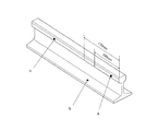
図2を参照して、端部熱処理レールに施される熱処理を説明する。図2(a)、(b)は、それぞれ端部熱処理レールの頭部の横断面図及び縦断面図を示しており、斜線部が熱処理が施される部位を示している。なお、ここで示す熱処理が施される部位は、JISにより規格化されたものであり(End Hardened Rails:JIS E 1123)、図中に示した数値の単位はmmである。 With reference to FIG. 2, the heat treatment applied to the end heat treatment rail will be described. 2 (a) and 2 (b) respectively show a cross-sectional view and a vertical cross-sectional view of the head of the end heat treatment rail, and the hatched portion shows a portion to be heat treated. In addition, the site | part to which the heat processing shown here was standardized by JIS (End Hardened Rails: JIS E 1123), and the unit of the numerical value shown in the figure is mm.
図2(a)に示すように、端部熱処理レールのレール頭頂部から15〜30mmの深さ及び頭部表面から10mmの深さに熱処理が施されている。また、図2(a)に示した深度の熱処理は、図2(b)に示すように、レール端から170mm(定常効果部100±10、逓減部40以下、軟化部20以下)の範囲に施されている。
As shown to Fig.2 (a), it heat-processed to the depth of 15-30 mm from the rail top part of an edge part heat processing rail, and the depth of 10 mm from the head surface. Also, the heat treatment at the depth shown in FIG. 2A is within a range of 170 mm from the rail end (steady effect part 100 ± 10, decreasing part 40 or less, softening
そのため、図3に示すように、レール端の頭部(図中a;以下、レール端頭部という)、レールの低部(図中b;以下、レール底部という)及びレール端から170mm以上離れたレール中央の頭部(図中c;以下、レール中央頭部という)の3箇所で、それぞれ交流磁場発生回路10による交流磁場の印加により発生する反磁場を磁場検出回路20及び測定器30で測定し、それぞれ得られた測定値を相対的に比較することにより、レールの種別を判別することが可能となる。
Therefore, as shown in FIG. 3, the head of the rail end (a in the figure; hereinafter referred to as the rail end head), the lower part of the rail (b in the figure; hereinafter referred to as the rail bottom), and a distance of 170 mm or more from the rail end. The magnetic
具体的に説明すると、普通レールでは熱処理が施されないため、上記した3箇所での測定値は全て同一の値となる。端部熱処理レールでは、上記したようにレール端から170mmの範囲に渡りレール端頭部に熱処理が施されているため、上記した3箇所のうちレール端頭部のみが、他の2箇所の測定値と異なる値となる。また、熱処理レールでは、レール頭部全体に熱処理が施されているため、上記した3箇所のうちレール低部のみが、他の2箇所の測定値と異なる値となる。 If it demonstrates concretely, since heat processing is not performed in a normal rail, all the measured values in the above-mentioned three places become the same value. In the end heat-treated rail, the rail end head is heat-treated over a range of 170 mm from the rail end as described above, so only the rail end head of the above-mentioned three locations is measured at the other two locations. The value is different from the value. Moreover, in the heat-treated rail, since the heat treatment is applied to the entire rail head, only the rail lower portion of the above-described three places has a value different from the measured values of the other two places.
このことから、表1に示すようにレールのレール端頭部、レール底部、レール中央頭部での反磁場を測定しその測定値を相対的に比較することにより、普通レール、端部熱処理レール、熱処理レールの3種類の種別を判別することができる。なお、表1は、レール中央頭部を基準として他の2箇所と比較した場合の測定値の違いの有無を示しており、測定値に違いが無い場合を○印で、違いがある場合を×印で示している。 From this, as shown in Table 1, by measuring the demagnetizing field at the rail end top, rail bottom, and rail center top of the rail and comparing the measured values relatively, the normal rail, end heat treated rail The three types of heat treatment rails can be discriminated. Table 1 shows whether there is a difference in the measured value when compared with the other two locations with the rail center head as a reference. A case where there is no difference in the measured value is indicated by a circle. This is indicated by a cross.
なお、レール種別判別装置1により測定する位置をレール端頭部、レール底部、レール中央頭部としたが、これに限らず、その他の位置であってもよい。また、レール種別判別装置1により測定する箇所を3箇所としたが、これに限らず、4箇所以上であってもよいし、2箇所以下であってもよい。また、頭頂部は、列車の重量や磨耗等で金属の組成が変化している可能性があるため、レール頭部を測定する際には、頭頂部を測定するのではなく、頭部の側部で測定することが好ましい。 In addition, although the position measured by the rail classification | category discrimination | determination apparatus 1 was made into the rail end head, a rail bottom part, and a rail center top, it is not restricted to this, Other positions may be sufficient. Moreover, although the location measured by the rail classification | category discriminating apparatus 1 was made into three places, it is not restricted to this, Four or more places may be sufficient and two places or less may be sufficient. In addition, since the metal composition of the top of the head may change due to the weight or wear of the train, when measuring the rail head, the head side is not measured. It is preferable to measure in parts.
以上のように、種別判別対象のレールの測定を行う位置を、レール端頭部、レール低部及びレール中央頭部としたことにより、普通レール、熱処理レール及び端部熱処理レールを判別することができる。 As described above, the normal rail, the heat-treated rail, and the end heat-treated rail can be identified by setting the position for measuring the rail to be classified as the rail end head, the rail lower portion, and the rail central head. it can.
また、既に敷設されているレールには、電車線から供給された電流を変電所へと送り返す帰線電流や列車検知のための列車検知軌条電流、電動機用電流等の信号電流が流れており、この信号電流と交流磁場発生回路10がレールに交流磁場を印加することで発生する渦電流とが干渉して、測定を妨げるビートが発生してしまう可能性がある。そのため、交流磁場発生回路10の可変交流電源12の周波数を調整することによって、干渉する二つの周波数を離すことによってビート現象の影響を減少させる。
In addition, on the rails that have already been laid, there are signal currents such as the return current that sends the current supplied from the train line back to the substation, the train detection rail current for train detection, the current for the motor, etc. This signal current and the eddy current generated when the AC magnetic
以下、ビートの減少処理について説明する。
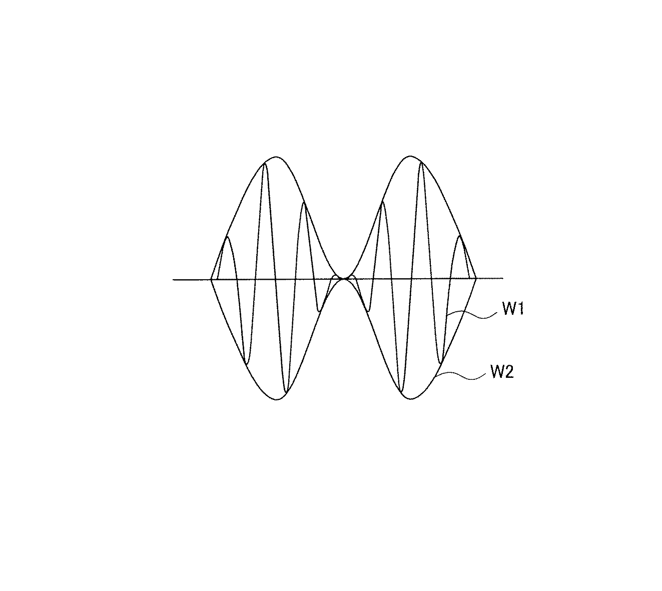
図4は、レールに流れる信号電流とレールに発生する渦電流との干渉により発生するビートを説明するための図である。ここで、信号電流の周波数をf1とし、電磁誘導によりレールに発生する渦電流の周波数をf2とする(ここで、f1≠f2)。なお、説明の簡略化のため二つの電流の振幅は等しいものとする。
Hereinafter, the beat reduction process will be described.
FIG. 4 is a diagram for explaining a beat generated by interference between a signal current flowing in the rail and an eddy current generated in the rail. Here, it is assumed that the frequency of the signal current is f1, and the frequency of the eddy current generated in the rail by electromagnetic induction is f2 (where f1 ≠ f2). For simplification of explanation, the amplitudes of the two currents are assumed to be equal.
図中W1は、信号電流の周波数f1の波形と渦電流の周波数f2の波形との干渉により合成された波形を示しており、図に示すとおり、振幅が定期的に強弱を繰返す波形となる。この振幅の変化に伴って、ビートが発生しその波形を図中W2で示している。なお、ここでビートの周波数は、|f1−f2|となる。 In the figure, W1 represents a waveform synthesized by interference between the waveform of the signal current frequency f1 and the waveform of the eddy current frequency f2, and as shown in the figure, the amplitude periodically becomes a waveform that repeatedly increases and decreases. As the amplitude changes, a beat is generated and its waveform is indicated by W2. Here, the beat frequency is | f1-f2 |.
ビートの周波数は、レールに流れる信号電流と交流磁場発生回路10の可変交流電源12が出力する交流電流との周波数の関係から、数Hzから数百Hzとなるが、レールには様々な周波数の電流が流れているため、レールに渦電流を発生するための交流電流の周波数を固定にしていると、ビートの周波数を100Hz以上にすることは困難である。ビートの周波数が100Hz程度以下になった場合は、測定器30で得られる測定値がビートの周波数に伴って変化してしまうため有効な値を読み取ることができない。
The beat frequency ranges from several Hz to several hundred Hz from the relationship between the frequency of the signal current flowing through the rail and the AC current output from the variable
一方、レール種別判別装置1は、信号処理回路22内に図1で示したような積分回路22aを有しており、ある程度はビートを圧縮することが可能であるが、レール敷設された場所によってはビートは1Hz以下になることもあり、それを圧縮するのに十分な時定数を選ぶと、時定数は数百秒にもなってしまうため測定に時間がかかり過ぎ、実用にならない。
On the other hand, the rail type discriminating apparatus 1 has an
そこで、干渉する二つの周波数差を、可変交流電源12の周波数を調整することによって大きくすることにより、積分回路22aでの圧縮に実用可能な時定数とすることが可能となり、測定器30にて有効な測定値を得ることができる。ここで、可変交流電源12の周波数を調整は、測定値の揺らぎ具合を判定する回路をさらに備え、その判定結果にもとづいて自動で調整を行うようにしてもよいし、測定器30に出力される測定値の揺らぎ具合から手動で調整を行うようにしてもよい。なお、周波数差は200Hz以上であることが好ましい。
Thus, by increasing the difference between the two interfering frequencies by adjusting the frequency of the variable
なお、ビートの圧縮が可能であり、測定が可能な状態(有効な測定値が読み取りが可能な状態)に可変交流電源12の周波数を調整したとしても、ビートは発生しているが、同一レールの同一部分であれば、常に同じ測定値となる。したがって、本発明でのレール種別の判別方法は、レールの特定の部分での測定値と他の部分での測定値とを相対的に比較することによって行うため、測定値自体に格別な厳密性は必要なく、有効な測定値の読み取り可能な状態であればレールの種別を判別することが可能である。
Note that even if the frequency of the variable
以上説明したように、レールに交流磁場を印加してレールに渦電流による反磁場を発生させ、この印加された交流磁場及びレールに生じた反磁場の変化を誘起電圧の変化として検出し、この検出された交流磁場と反磁場とによる誘起電圧の位相差を測定するに際し、レールに発生した渦電流とレールに流れる信号電流との干渉を回避するために渦電流と信号電流との周波数の差を所定の値以上となるように可変交流電源12の周波数を調整するようにしたことにより、レールに流れる信号電流の影響を受けずに、交流磁場と反磁場とによる誘起電圧の位相差を測定することが可能であり、このように得られた複数箇所の測定値を相対的に比較することによって、レールの種別を容易に判別することができる。
As described above, an AC magnetic field is applied to the rail to generate a demagnetizing field due to the eddy current in the rail, and the applied AC magnetic field and the change in the demagnetizing field generated in the rail are detected as a change in induced voltage. When measuring the phase difference of the induced voltage due to the detected alternating magnetic field and demagnetizing field, the frequency difference between the eddy current and the signal current is used to avoid interference between the eddy current generated in the rail and the signal current flowing in the rail. By adjusting the frequency of the variable
本実施の形態におけるレール種別判別装置1の細部構成及び詳細動作に関しては、本発明の趣旨を逸脱しない範囲で適宜変更可能である。 The detailed configuration and detailed operation of the rail type determination device 1 in the present embodiment can be changed as appropriate without departing from the spirit of the present invention.
1 レール種別判別装置
10 交流磁場発生回路
11 コイル
12 可変交流電源
20 磁場検出回路
21 コイル
22 信号処理回路
22a 積分回路
30 測定器
1 Rail
Claims (4)
前記交流磁場及び当該交流磁場を受けて前記レールに生じる渦電流による反磁場の変化を誘起電圧の変化として検出する磁場検出手段と、
前記検出された交流磁場及び反磁場による誘起電圧の位相差を測定する測定手段と、
前記交流磁場の周波数を調整する調整手段と、
を備えたことを特徴とするレール種別判別装置。 Magnetic field generating means for applying an alternating magnetic field to the rail;
A magnetic field detecting means for detecting a change in a demagnetizing field caused by an eddy current generated in the rail in response to the alternating magnetic field and the alternating magnetic field as a change in induced voltage;
Measuring means for measuring the phase difference of the induced voltage due to the detected alternating magnetic field and demagnetizing field;
Adjusting means for adjusting the frequency of the alternating magnetic field;
A rail type discrimination device comprising:
当該交流磁場及び当該交流磁場を受けて前記レールに生じる渦電流による反磁場の変化を誘起電圧の変化として検出する工程と、
前記検出された交流磁場及び反磁場による誘起電圧の位相差を測定する工程と、
前記測定された値に基づいて前記交流磁場の周波数を調整する工程と、
を含むことを特徴とするレール種別判別方法。 Applying an alternating magnetic field to the rail;
Detecting a change in the demagnetizing field due to the eddy current generated in the rail in response to the alternating magnetic field and the alternating magnetic field, as a change in induced voltage;
Measuring the phase difference of the induced voltage due to the detected alternating magnetic field and demagnetizing field;
Adjusting the frequency of the alternating magnetic field based on the measured value;
A rail type discrimination method comprising:
Priority Applications (1)
| Application Number | Priority Date | Filing Date | Title |
|---|---|---|---|
| JP2004108954A JP2005291990A (en) | 2004-04-01 | 2004-04-01 | Rail classification discriminating apparatus and rail classification discriminating method |
Applications Claiming Priority (1)
| Application Number | Priority Date | Filing Date | Title |
|---|---|---|---|
| JP2004108954A JP2005291990A (en) | 2004-04-01 | 2004-04-01 | Rail classification discriminating apparatus and rail classification discriminating method |
Publications (1)
| Publication Number | Publication Date |
|---|---|
| JP2005291990A true JP2005291990A (en) | 2005-10-20 |
Family
ID=35325074
Family Applications (1)
| Application Number | Title | Priority Date | Filing Date |
|---|---|---|---|
| JP2004108954A Pending JP2005291990A (en) | 2004-04-01 | 2004-04-01 | Rail classification discriminating apparatus and rail classification discriminating method |
Country Status (1)
| Country | Link |
|---|---|
| JP (1) | JP2005291990A (en) |
-
2004
- 2004-04-01 JP JP2004108954A patent/JP2005291990A/en active Pending
Similar Documents
| Publication | Publication Date | Title |
|---|---|---|
| JP5262436B2 (en) | Magnetic measurement method and apparatus | |
| JP5299718B2 (en) | Induction hardening management system | |
| Daura et al. | Wireless power transfer based non-destructive evaluation of cracks in aluminum material | |
| CN101802229B (en) | High frequency quenching monitoring device | |
| WO2013080587A1 (en) | Pipeline ac corrosion risk measurement and evaluation method and measurement and evaluation device | |
| US9146279B2 (en) | Method for detection of interlaminar sheet short circuits in the stator sheet core of electromachines | |
| US6815957B2 (en) | Method and device for inspecting laminated iron cores of electrical machines for interlamination shorts | |
| DE59909858D1 (en) | METHOD AND DEVICE FOR DETECTING UNEQUALNESSES IN THE WALL THICKNESS OF INAccessible METAL PIPES | |
| US5391988A (en) | Method and apparatus for detecting flaws within a conductive object while cancelling the effects of variation in distance between the detection apparatus and the conductive object | |
| US11215600B2 (en) | Device for the in-line measurement of the percentage of austenite in steels | |
| JP2016070811A (en) | Magnetic characteristics measuring apparatus, magnetic characteristics measuring method, and program | |
| US20150276675A1 (en) | Alternating Current Field Measurement System | |
| JP2005291990A (en) | Rail classification discriminating apparatus and rail classification discriminating method | |
| DE50108834D1 (en) | Method and device for determining the quality of a cable | |
| JP2009168556A (en) | Quenching inspection device and quenching inspection method | |
| JP2015040317A (en) | Method of measuring cathode corrosion protection condition of buried pipeline | |
| KR100675061B1 (en) | Method of manufacturing steel strip or surface treatment steel strip | |
| JP2012078349A (en) | Pulse excitation type inspection device, and pulse excitation type inspection method | |
| CA2463590C (en) | Method and device for inspecting laminated iron cores of electrical machines for interlamination shorts | |
| JP2008216091A (en) | Rail rail bottom corrosion detector | |
| JP3223991U (en) | Nondestructive inspection equipment | |
| JP3589975B2 (en) | Method and apparatus for measuring wear of Alsas train lines | |
| JPH0827262B2 (en) | Corrosion degradation determination method for double-layer metal wire | |
| JP2005227003A (en) | Method and apparatus for judging quality of connecting portion of steel core aluminum strand | |
| Smetana et al. | Pulsed excitation in eddy current non-destructive testing of conductive materials |