WO2013080587A1 - Pipeline ac corrosion risk measurement and evaluation method and measurement and evaluation device - Google Patents
Pipeline ac corrosion risk measurement and evaluation method and measurement and evaluation device Download PDFInfo
- Publication number
- WO2013080587A1 WO2013080587A1 PCT/JP2012/064379 JP2012064379W WO2013080587A1 WO 2013080587 A1 WO2013080587 A1 WO 2013080587A1 JP 2012064379 W JP2012064379 W JP 2012064379W WO 2013080587 A1 WO2013080587 A1 WO 2013080587A1
- Authority
- WO
- WIPO (PCT)
- Prior art keywords
- coupon
- frequency
- current density
- corrosion
- current
- Prior art date
Links
Images

Classifications
-
- G—PHYSICS
- G01—MEASURING; TESTING
- G01N—INVESTIGATING OR ANALYSING MATERIALS BY DETERMINING THEIR CHEMICAL OR PHYSICAL PROPERTIES
- G01N17/00—Investigating resistance of materials to the weather, to corrosion, or to light
- G01N17/04—Corrosion probes
- G01N17/043—Coupons
-
- G—PHYSICS
- G01—MEASURING; TESTING
- G01N—INVESTIGATING OR ANALYSING MATERIALS BY DETERMINING THEIR CHEMICAL OR PHYSICAL PROPERTIES
- G01N17/00—Investigating resistance of materials to the weather, to corrosion, or to light
- G01N17/02—Electrochemical measuring systems for weathering, corrosion or corrosion-protection measurement
Definitions
- the present invention relates to a measurement evaluation method and a measurement evaluation apparatus for measuring and evaluating a pipeline AC corrosion risk by measuring a coupon current.
- pipelines metal pipelines buried in the ground (hereinafter simply referred to as pipelines) are coated with a high-resistance plastic coating on the outer surface, and are also used for high-voltage AC transmission lines and AC electricity.
- the need for measuring and assessing AC corrosion risk is increasing due to the increasing number of parallel laying conditions over rail transport routes.
- the source of the AC corrosion is a high-voltage AC transmission line parallel to the pipeline or an AC electric railway transportation system.
- AC corrosion occurs in a coating defect portion of a pipeline in a state where an AC induced voltage is generated in the pipeline under the influence of these AC corrosion sources. Therefore, the alternating current density I AC [A / m 2 ] in the area of the coating defect portion is an index for grasping the alternating current corrosion rate.
- the alternating current density I AC [A / m 2 ] in the area S [m 2 ] of the coating defect portion can be expressed by the following equation.
- j Imaginary unit ⁇ : 2 ⁇ f (f: frequency of current flowing through the transmission line and train line) M: Mutual inductance between transmission line, train line and embedded coating pipeline I: Transmission line current, train line current L: Parallel distance between transmission line, train line and embedded coating pipeline
- AC induction voltage V AC is large (i.e., transmission line current of the high-voltage AC power lines and AC electric railway transportation system, a large train current and / or power lines, and the contact line and the pipeline
- V AC transmission line current of the high-voltage AC power lines and AC electric railway transportation system, a large train current and / or power lines, and the contact line and the pipeline
- the resistivity ⁇ of the electrolyte in contact with the coating defect portion is low, and if the area S of the coating defect portion is small, the AC current density I AC increases. AC corrosion rate increases.
- coupon current density is a model of a coating defect part of a pipeline, and is a metal piece having a known surface area made of the same metal material as that of the pipeline (see Non-Patent Document 2 below).
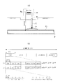
- FIG. 1 is an explanatory diagram showing a method of measuring a coupon current density in a pipeline.
- a coupon C is embedded in the vicinity of a pipeline P embedded in the ground, and the coupon C and the pipeline P are electrically connected by an electric wire W.
- the outer surface of the pipeline P is covered with a coating P1 made of a plastic material, and the surface area A of the tip C1 of the coupon C simulates a defective portion of the coating P1.
- the electric wire W that electrically connects the coupon C and the pipeline P is provided with a shunt resistor Rs, and the coupon DC current density I DC and the coupon AC are measured by the measuring device M that measures the current (coupon current) flowing through the shunt resistor Rs.
- the current density I AC is determined.
- the coupon DC current density I DC and the coupon AC current density I AC are the coupon current measurement values (I (1), I (2), I (3), ).
- the coupon DC current density I DC and the coupon AC current density I AC are defined as one subunit with the AC cycle of the AC corrosion source (for example, high-voltage AC power transmission line and / or AC electric railway transport system) as one subunit. It is defined to obtain a set of coupon DC current density I DC and coupon AC current density I AC for each unit, and the average value I DC ave of coupon DC current density I DC for each unit composed of a plurality of subunits. , Maximum value I DC max , minimum value I DC min , average value I AC ave of coupon AC current density I AC , maximum value I AC max , and minimum value I AC min are obtained.
- the example shown in FIG. 1B is a case where the commercial AC frequency of the AC corrosion source is 50 Hz (cycle is 20 ms).
- one subunit is set to 20 ms, and 200 measured values (I (1), I (2), I (3),... I (199), I (200) in this one subunit. ) Is sampled.
- coupon DC current density I DC and the coupon AC current density I AC defined by the above-described equation are obtained, it is assumed that the commercial AC frequency of the AC corrosion source is known in advance.
- a set of coupon DC current density I DC and coupon AC current density I AC is obtained by dividing the subunits by one cycle of frequency.
- the frequency of the high-voltage AC transmission line and the AC electric railway transport system is the same 50 Hz.
- the frequency of high-voltage AC power transmission lines in Japan is 50 Hz in eastern Japan and 60 Hz in west Japan, but the Tokaido Shinkansen is operated at 60 Hz from Tokyo.
- the coupon DC current density I DC and the coupon AC current density I AC have been measured with a fixed subunit targeting one commercial AC frequency, and different commercial AC frequencies are used. There was a problem that the measurement evaluation device could not be used together between regions. Then, using the measurement and evaluation device for the fixed subunit, the coupon AC current density I AC is obtained for the commercial AC frequency having a period different from the measurement time of the fixed subunit. There was a problem that the coupon alternating current density I AC could not be obtained.
- the present invention is an example of a problem to deal with such a problem. That is, in the measurement and evaluation method and measurement evaluation apparatus for AC corrosion risk in pipelines, it is possible to provide a measurement evaluation method and measurement evaluation apparatus that can be used together in regions where different commercial AC frequencies are operated, and different commercial AC frequencies in one measurement evaluation apparatus It is possible to obtain a precise coupon AC current density suitable for assessing the AC corrosion risk for each region where AC is operated, and when the AC corrosion source cannot be clearly identified at the coupon current density measurement point, or a different commercial For the purpose of the present invention, it is possible to obtain a precise coupon alternating current density suitable for evaluating the risk of alternating current corrosion even when the influence of alternating current corrosion sources using alternating frequency is mixed. is there.
- the AC corrosion risk measurement evaluation method and measurement evaluation apparatus in the pipeline of the present invention have at least the following configurations.
- a coupon is connected to a metal pipeline buried in the ground, and a method of evaluating the AC corrosion risk of a pipeline by a coupon DC current density and a coupon AC current density obtained from a measured value of the coupon current, A frequency identification process for identifying the frequency of the AC corrosion source from the measured current waveform, and one cycle of the identified frequency as one unit time, a set of coupon direct currents from the measured value of the coupon current within the unit time.
- a coupon current density calculating step for obtaining a current density and a coupon alternating current density wherein the frequency specifying step sequentially selects one frequency among the commercial alternating frequencies of 16-2 / 3 Hz, 50 Hz, and 60 Hz,
- the coupon current measurement value waveform is cut out in one cycle of the selected frequency, and the difference between the appearance time of the maximum value and the minimum value of the cut-out waveform is
- a device for connecting a coupon to a metal pipeline buried in the ground and evaluating the AC corrosion risk of the pipeline based on the coupon DC current density and the coupon AC current density obtained from the measured value of the coupon current A set of coupon direct currents from the measured value of coupon current within one unit time, with frequency specifying means for specifying the frequency of the AC corrosion source from the measured current waveform and one period of the specified frequency as one unit time.
- a coupon current density calculating means for obtaining a current density and a coupon alternating current density, and the frequency specifying means sequentially selects one frequency from 16-2 / 3 Hz, 50 Hz, and 60 Hz, which are commercial AC frequencies.
- Cut out the measured value waveform of the coupon current in one cycle of the selected frequency, and the difference between the appearance time of the maximum value and the minimum value of the cut out waveform A pipeline characterized in that it is determined whether or not it matches half of one cycle of the selected frequency, and if the result of the determination matches, the selected frequency is specified as the frequency of the AC corrosion source AC corrosion risk measurement and evaluation equipment in Japan.
- the present invention can provide a measurement evaluation method and a measurement evaluation apparatus that can be used together in regions where different commercial AC frequencies are operated by providing such a feature. Moreover, the precise
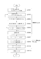
- FIG. 2 is an explanatory diagram (process flow) showing a method for measuring and evaluating an AC corrosion risk in a pipeline according to an embodiment of the present invention.
- the measurement evaluation method according to the embodiment of the present invention is similar to the method shown in FIG. 1, in which a coupon C is connected to a metal pipeline P buried in the ground, and the coupon is obtained from the measured value of the coupon current.
- This is a method for evaluating the AC corrosion risk of the pipeline P based on the AC current density.
- the frequency specifying step specifies the frequency of the AC corrosion source from the measured value waveform of the coupon current, and one cycle of the specified frequency is one unit. As a time, it has a coupon current density calculation process which calculates
- the frequency specifying step is a step for specifying the frequency of the AC corrosion source that generates the AC induction voltage in the pipeline P. By providing this step, the frequency of the AC corrosion source can be specified from the measured waveform of the coupon current regardless of whether the frequency of the AC corrosion source is predictable or unpredictable.
- the coupon current I (t) is measured at a sampling interval set for a predetermined time (STEP 1).
- the sampling interval here is preferably a fine interval (for example, 0.1 ms interval) at which the periodic change of commercial AC frequencies of 16-2 / 3 Hz, 50 Hz, and 60 Hz can be clearly grasped.
- the measured coupon current I (t) is stored in the storage means as time series data corresponding to the appearance time.
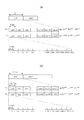
- FIG. 3 is an explanatory view showing a specific example of the above-described frequency specifying step.
- a measured value waveform (time series data) of the coupon current I (t) is obtained, first, 60 Hz is selected as the frequency Fb. Since one period T 1 of 60 Hz is 16.7 ms, as shown in FIG. 3A, the measured value waveform is cut out in one period T 1 , and the appearance time t max and the minimum value of the maximum value of the cut out waveform are shown. The appearance time difference ⁇ t of the appearance time t min is obtained. Then, it is determined whether or not the obtained ⁇ t is equal to (1/2) ⁇ T 1 .
- FIG. 3 is an explanatory view showing a specific example of the above-described frequency specifying step.
- the above-mentioned 1 unit time is set as a subunit, and further, one unit in which a plurality of the subunits are continued is set (STEP 7). Then, the coupon direct current density I DC and the coupon alternating current density I AC are obtained for each subunit (STEP 8). At this time, in order to obtain the coupon alternating current density I AC , it is necessary to obtain the coupon direct current density I DC inevitably.
- the coupon DC current density I DC and the coupon AC current density I AC obtained for each subunit are compared within one unit, and the average values I DC ave , I AC ave , and the maximum value I DC max within one unit are compared.
- I AC max , minimum values I DC min , I AC min are obtained (STEP 9). Then, these values (I DC ave, I DC max , I DC min, I AC ave, I AC max, I AC min) by evaluating the AC corrosion risk of the pipeline (STEP 10).
- FIG. 4 is an explanatory diagram showing a specific example of the coupon current density calculation step.
- One subunit and one unit at each frequency Fb after the frequency Fb is specified can be set as shown in Table 1 below.
- a high-speed railway refers to a train that travels through a major section at a speed of 200 km / h or higher, and a route therefor, which matches the definition of the Japanese Shinkansen. If the length of the high-speed railway vehicle is 25 m and the 16-car train is set, the length of one train is 400 m. This high-speed railway requires 7.2 seconds to pass the coupon current density measurement point at a speed of 200 km / h. Therefore, if the measurement time of one unit is set to 8.35 to 12 s, it is possible to sufficiently grasp the AC corrosion risk generated in the pipeline due to the passage of the high-speed railway at any frequency.
- FIG. 4A shows an example of calculating the coupon current density when the frequency Fb is specified as 16-2 / 3 Hz.
- the measurement time of one subunit is set to 60 ms
- the measurement time of one unit is set to 12 s
- the coupon DC current density I DC and the coupon AC current density I AC are set. Is obtained by the following equations (3) and (4).
- FIG. 4B shows an example of calculating the coupon current density when the frequency Fb is specified as 60 Hz.
- the measurement time of one subunit is set to 16.7 ms
- the measurement time of one unit is set to 8.35 s
- the coupon DC current density I DC and the coupon AC are set.
- the current density I AC is obtained by the following equations (5) and (6).
- a calculation example of the coupon current density when the frequency Fb is specified as 50 Hz is as shown in FIG. 1B, and the calculation formula is as shown in the above-described formulas (1) and (2).
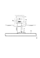
- FIG. 5 is an explanatory diagram showing an AC corrosion risk measurement / evaluation apparatus in a pipeline according to an embodiment of the present invention.
- This measurement / evaluation apparatus 10 connects a coupon C to a metal pipeline P buried in the ground, and the AC corrosion of the pipeline P is determined by the coupon DC current density and the coupon AC current density obtained from the measured value of the coupon current.
- It is an apparatus for evaluating risk, and includes a frequency specifying means 11 and a coupon current density calculating means 12.
- the frequency specifying means 11 can be configured by a control device such as a portable PC or a programmable controller, and executes the above-described frequency specifying process by the measured value waveform of the coupon current I (t) obtained from the coupon current density calculating means 12. It has a program to do.
- the frequency specified by the frequency specifying unit 11 is output to the coupon current density calculating unit 12.
- the coupon current density calculating unit 12 includes a program for executing the above-described coupon current density calculating step, and the measurement time of one subunit and one unit is set from the frequency specified by the frequency specifying unit 11,
- the coupon DC current density I DC and coupon AC current density I AC are calculated for each subunit from the coupon current I (t) measured at a sampling interval of 1 ms, and I DC ave , I DC max , I DC min , I AC ave , I AC max , and I AC min are obtained.
- the frequency of the AC corrosion source is specified by the measured coupon current I (t). Therefore, the measurement time of one subunit and one unit is set each time based on the specified frequency. This makes it possible to obtain a coupon direct current density I DC coupon alternating current density I AC which is an index for evaluating the AC corrosion risk precise value.
- coupon DC current can be used as an index for evaluating AC corrosion risk without causing a difference in commercial AC frequency for each area.
- the density I DC and the coupon alternating current density I AC can be obtained with precise values.
- measurement evaluation is performed even when the source of AC corrosion cannot be clearly identified at the coupon current density measurement point, or even when the effects of AC corrosion sources using different commercial AC frequencies are mixed.
- the coupon DC current density I DC and the coupon AC current density I AC can be obtained with precise values based on the specified frequency.
Landscapes
- Life Sciences & Earth Sciences (AREA)
- Analytical Chemistry (AREA)
- Chemical & Material Sciences (AREA)
- Environmental & Geological Engineering (AREA)
- Environmental Sciences (AREA)
- Biochemistry (AREA)
- Health & Medical Sciences (AREA)
- Ecology (AREA)
- Biodiversity & Conservation Biology (AREA)
- Physics & Mathematics (AREA)
- General Health & Medical Sciences (AREA)
- General Physics & Mathematics (AREA)
- Immunology (AREA)
- Pathology (AREA)
- Investigating Or Analyzing Materials By The Use Of Electric Means (AREA)
- Testing Resistance To Weather, Investigating Materials By Mechanical Methods (AREA)
- Prevention Of Electric Corrosion (AREA)
Abstract
Provided is a measurement and evaluation method which may be used in areas in which different commercial AC frequencies are in operation. According to the present invention, a coupon is connected to a metal pipeline buried underground, and a pipeline AC corrosion risk is evaluated by a coupon DC density and a coupon AC density obtained from a coupon current measurement. The present invention comprises identifying a frequency of an AC corrosion source from a coupon current measurement waveform, and calculating a coupon current density to obtain a set comprising the coupon DC density and the coupon AC density from the coupon current measurement of one unit hour with one period of the identified frequency being the one unit hour.
Description
本発明は、クーポン電流を計測することでパイプラインの交流腐食リスクを計測評価する計測評価方法及び計測評価装置に関するものである。
The present invention relates to a measurement evaluation method and a measurement evaluation apparatus for measuring and evaluating a pipeline AC corrosion risk by measuring a coupon current.
近年、地中に埋設されている金属製のパイプライン(以下、これを単にパイプラインという)は、外表面が高抵抗率のプラスチックコーティングで被覆されており、また、高圧交流送電線や交流電気鉄道輸送路と長距離にわたって並行して敷設される状況が増えていることから、交流腐食リスクを計測評価することの必要性が高まっている。パイプラインの交流腐食事例の解析結果によると、交流腐食の発生源はパイプラインと並行する高圧交流送電線または交流電気鉄道輸送システムであると言える。交流腐食は、これらの交流腐食発生源の影響を受けてパイプラインに交流誘導電圧が発生している状態でパイプラインのコーティング欠陥部で生じる。したがって、コーティング欠陥部の面積における交流電流密度IAC[A/m2]が交流腐食速度を把握するための指標になる。
In recent years, metal pipelines buried in the ground (hereinafter simply referred to as pipelines) are coated with a high-resistance plastic coating on the outer surface, and are also used for high-voltage AC transmission lines and AC electricity. The need for measuring and assessing AC corrosion risk is increasing due to the increasing number of parallel laying conditions over rail transport routes. According to the analysis result of the AC corrosion case of the pipeline, it can be said that the source of the AC corrosion is a high-voltage AC transmission line parallel to the pipeline or an AC electric railway transportation system. AC corrosion occurs in a coating defect portion of a pipeline in a state where an AC induced voltage is generated in the pipeline under the influence of these AC corrosion sources. Therefore, the alternating current density I AC [A / m 2 ] in the area of the coating defect portion is an index for grasping the alternating current corrosion rate.
コーティング欠陥部の面積S[m2]における交流電流密度IAC[A/m2]は、IAC=VAC/(R・S)となり(ここで、VAC:パイプラインに生じている交流誘導電圧,R:コーティング欠陥部の接地抵抗)、コーティング欠陥部を直径d[m]の円形とすると、コーティング欠陥部の接地抵抗R[Ω]は、R=ρ/(2d)で表される(ここで、ρ:電解質の抵抗率[Ω・m];下記非特許文献1参照)。これによって、コーティング欠陥部の面積S[m2]における交流電流密度IAC[A/m2]は、以下の式で表すことができる。

ここで、
j:虚数単位
ω:2πf(f:送電線、電車線を流れる電流の周波数)
M:送電線、電車線と埋設されたコーティングパイプラインとの相互インダクタンス
I:送電線電流、電車線電流
L:送電線、電車線と埋設されたコーティングパイプラインとの並行距離 The AC current density I AC [A / m 2 ] in the area S [m 2 ] of the coating defect portion is I AC = V AC / (R · S) (where V AC : AC generated in the pipeline) Inductive voltage, R: Ground resistance of coating defect portion), and assuming that the coating defect portion is a circle having a diameter d [m], the ground resistance R [Ω] of the coating defect portion is represented by R = ρ / (2d). (Where ρ is the resistivity of the electrolyte [Ω · m]; see Non-PatentDocument 1 below). Thereby, the alternating current density I AC [A / m 2 ] in the area S [m 2 ] of the coating defect portion can be expressed by the following equation.
here,
j: Imaginary unit ω: 2πf (f: frequency of current flowing through the transmission line and train line)
M: Mutual inductance between transmission line, train line and embedded coating pipeline I: Transmission line current, train line current L: Parallel distance between transmission line, train line and embedded coating pipeline
j:虚数単位
ω:2πf(f:送電線、電車線を流れる電流の周波数)
M:送電線、電車線と埋設されたコーティングパイプラインとの相互インダクタンス
I:送電線電流、電車線電流
L:送電線、電車線と埋設されたコーティングパイプラインとの並行距離 The AC current density I AC [A / m 2 ] in the area S [m 2 ] of the coating defect portion is I AC = V AC / (R · S) (where V AC : AC generated in the pipeline) Inductive voltage, R: Ground resistance of coating defect portion), and assuming that the coating defect portion is a circle having a diameter d [m], the ground resistance R [Ω] of the coating defect portion is represented by R = ρ / (2d). (Where ρ is the resistivity of the electrolyte [Ω · m]; see Non-Patent
j: Imaginary unit ω: 2πf (f: frequency of current flowing through the transmission line and train line)
M: Mutual inductance between transmission line, train line and embedded coating pipeline I: Transmission line current, train line current L: Parallel distance between transmission line, train line and embedded coating pipeline
この式から明らかなように、交流誘導電圧VACが大きい(すなわち、高圧交流送電線や交流電気鉄道輸送システムの送電線電流,電車電流が大きい、及び/または送電線,電車線とパイプラインとの並行距離が長い)ほど、コーティング欠陥部に接する電解質の抵抗率ρが低いほど、コーティング欠陥部の面積Sが小さいほど、交流電流密度IACは大きくなり、交流腐食速度が大きくなる。また、別の見方をすると、交流電圧VACがそれほど大きくなくても、コーティング欠陥部に接する電解質の抵抗率ρが低く、コーティング欠陥部の面積Sが小さいと交流電流密度IACは大きくなり、交流腐食速度が大きくなる。
As is apparent from this equation, AC induction voltage V AC is large (i.e., transmission line current of the high-voltage AC power lines and AC electric railway transportation system, a large train current and / or power lines, and the contact line and the pipeline The longer the parallel distance is), the lower the resistivity ρ of the electrolyte in contact with the coating defect portion, and the smaller the area S of the coating defect portion, the higher the alternating current density I AC and the higher the AC corrosion rate. From another viewpoint, even if the AC voltage V AC is not so large, the resistivity ρ of the electrolyte in contact with the coating defect portion is low, and if the area S of the coating defect portion is small, the AC current density I AC increases. AC corrosion rate increases.
地中に埋設されているコーティングパイプラインにおけるコーティング欠陥部の交流電流密度は、実際には計測不可能である。そこで、パイプラインの交流腐食リスクは、パイプラインに近接して埋設されたクーポンとパイプラインとを電気的に接続し、その接続電線を流れる電流の計測値から得られるクーポン直流電流密度とクーポン交流電流密度の2つの値(この2つの値を総称してクーポン電流密度という)を、クーポン電流密度を指標としたカソード防食基準と照査することで評価している。ここでいうクーポンとは、パイプラインのコーティング欠陥部を模擬したものであり、パイプラインと同じ金属材料で作られた表面積が既知の金属片である(下記非特許文献2参照)。
Actual AC density of coating defects in coating pipelines buried in the ground cannot be measured. Therefore, the risk of AC corrosion in the pipeline is that the coupon DC current density and coupon AC obtained from the measured value of the current flowing through the connecting wire are electrically connected to the coupon embedded in the pipeline. Two values of current density (the two values are collectively referred to as a coupon current density) are evaluated by checking against the cathodic protection standard using the coupon current density as an index. The coupon here is a model of a coating defect part of a pipeline, and is a metal piece having a known surface area made of the same metal material as that of the pipeline (see Non-Patent Document 2 below).
図1は、パイプラインにおけるクーポン電流密度の計測方法を示した説明図である。図1(a)に示すように、地中に埋設されたパイプラインPに近接してクーポンCを埋設し、クーポンCとパイプラインPとを電線Wで電気的に接続する。パイプラインPの外表面はプラスチック材料のコーティングP1で被覆されており、クーポンCの先端部C1の表面積AがコーティングP1の欠陥部を模擬している。クーポンCとパイプラインPを電気的に接続する電線Wにはシャント抵抗Rsが設けられ、シャント抵抗Rsに流れる電流(クーポン電流)を計測する計測装置Mによって、クーポン直流電流密度IDCとクーポン交流電流密度IACが求められる。
FIG. 1 is an explanatory diagram showing a method of measuring a coupon current density in a pipeline. As shown in FIG. 1A, a coupon C is embedded in the vicinity of a pipeline P embedded in the ground, and the coupon C and the pipeline P are electrically connected by an electric wire W. The outer surface of the pipeline P is covered with a coating P1 made of a plastic material, and the surface area A of the tip C1 of the coupon C simulates a defective portion of the coating P1. The electric wire W that electrically connects the coupon C and the pipeline P is provided with a shunt resistor Rs, and the coupon DC current density I DC and the coupon AC are measured by the measuring device M that measures the current (coupon current) flowing through the shunt resistor Rs. The current density I AC is determined.
図1(b)に示した例では、クーポン直流電流密度IDCとクーポン交流電流密度IACは、0.1ms間隔でサンプリングされたクーポン電流の計測値(I(1),I(2),I(3),…)から求められる。この際、クーポン直流電流密度IDCとクーポン交流電流密度IACは、交流腐食発生源(例えば、高圧交流送電線及び/または交流電気鉄道輸送システム)の交流周期を1サブユニットとして、1サブユニット毎に一組のクーポン直流電流密度IDCとクーポン交流電流密度IACを求めるように定義されており、複数のサブユニットからなる1ユニット毎に、クーポン直流電流密度IDCの平均値IDC
ave,最大値IDC
max,最小値IDC
min、クーポン交流電流密度IACの平均値IAC
ave,最大値IAC
max,最小値IAC
minを求めている。
In the example shown in FIG. 1B, the coupon DC current density I DC and the coupon AC current density I AC are the coupon current measurement values (I (1), I (2), I (3), ...). At this time, the coupon DC current density I DC and the coupon AC current density I AC are defined as one subunit with the AC cycle of the AC corrosion source (for example, high-voltage AC power transmission line and / or AC electric railway transport system) as one subunit. It is defined to obtain a set of coupon DC current density I DC and coupon AC current density I AC for each unit, and the average value I DC ave of coupon DC current density I DC for each unit composed of a plurality of subunits. , Maximum value I DC max , minimum value I DC min , average value I AC ave of coupon AC current density I AC , maximum value I AC max , and minimum value I AC min are obtained.
図1(b)に示した例は、交流腐食発生源の商用交流周波数が50Hz(周期が20ms)の場合である。この場合には、1サブユニットが20msに設定され、この1サブユニットで200個の計測値(I(1),I(2),I(3),…I(199),I(200))がサンプリングされる。そして、この計測値I(t)(t=1~200)から、下記(1),(2)式によってクーポン直流電流密度IDCとクーポン交流電流密度IACが求められる(式中のAはクーポンの表面積)。
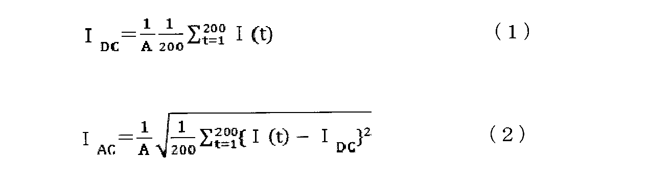
The example shown in FIG. 1B is a case where the commercial AC frequency of the AC corrosion source is 50 Hz (cycle is 20 ms). In this case, one subunit is set to 20 ms, and 200 measured values (I (1), I (2), I (3),... I (199), I (200) in this one subunit. ) Is sampled. Then, from this measured value I (t) (t = 1 to 200), the coupon DC current density I DC and the coupon AC current density I AC are obtained by the following formulas (1) and (2) (A in the formula is Coupon surface area).
前述した式で定義されるクーポン直流電流密度IDCとクーポン交流電流密度IACを求める際には、交流腐食発生源の商用交流周波数が予め判っていることが前提になっており、その商用交流周波数の1周期でサブユニットを区切って一組のクーポン直流電流密度IDCとクーポン交流電流密度IACを求めている。しかしながら、交流腐食発生源の商用交流周波数には、16-2/3Hz,50Hz,60Hzの3種類があり、地域毎と用途毎に異なる周波数で運用されている。例えば、フランスのように高圧交流送電線と交流電気鉄道輸送システムの周波数が同一の50Hzの国もあれば、ドイツのように高圧交流送電線は50Hz、交流電気鉄道輸送システムは16-2/3Hzという国もある。日本の高圧交流送電線の周波数は、東日本が50Hzで西日本が60Hzであるが、東海道新幹線は東京から60Hzで運転されているので、関東地区は50Hzと60Hzが交流腐食発生源の周波数となり得る。
When the coupon DC current density I DC and the coupon AC current density I AC defined by the above-described equation are obtained, it is assumed that the commercial AC frequency of the AC corrosion source is known in advance. A set of coupon DC current density I DC and coupon AC current density I AC is obtained by dividing the subunits by one cycle of frequency. However, there are three types of commercial AC frequencies of AC corrosion generating sources: 16-2 / 3 Hz, 50 Hz, and 60 Hz, which are operated at different frequencies for each region and for each application. For example, in some countries, such as France, the frequency of the high-voltage AC transmission line and the AC electric railway transport system is the same 50 Hz. There is also a country. The frequency of high-voltage AC power transmission lines in Japan is 50 Hz in eastern Japan and 60 Hz in west Japan, but the Tokaido Shinkansen is operated at 60 Hz from Tokyo.
これに対して、これまでのクーポン直流電流密度IDCとクーポン交流電流密度IACの計測は、一つの商用交流周波数を対象にした固定サブユニットで行われており、異なる商用交流周波数を運用する地域間で計測評価装置を併用することができない問題があった。そして、固定サブユニットの計測評価装置を用いて、固定サブユニットの計測時間と異なる周期の商用交流周波数に対してクーポン交流電流密度IACを求めると、交流腐食リスクを評価するために適する精緻なクーポン交流電流密度IACを得ることができない問題があった。
On the other hand, the coupon DC current density I DC and the coupon AC current density I AC have been measured with a fixed subunit targeting one commercial AC frequency, and different commercial AC frequencies are used. There was a problem that the measurement evaluation device could not be used together between regions. Then, using the measurement and evaluation device for the fixed subunit, the coupon AC current density I AC is obtained for the commercial AC frequency having a period different from the measurement time of the fixed subunit. There was a problem that the coupon alternating current density I AC could not be obtained.
また、クーポン電流密度の計測地点で、交流腐食発生源を明確に特定できない場合や、異なる商用交流周波数を用いた交流腐食発生源の影響が混在している場合があり、計測時においてクーポン電流密度を求めるためのサブユニットの計測時間を設定できない場合がある。このような場合にも、予め設定していた固定サブユニットの計測時間とパイプラインに影響している交流腐食発生源の交流周期が異なる場合には、交流腐食リスクを評価するために適する精緻なクーポン交流電流密度IACを得ることができない問題があった。
In addition, there are cases where the AC corrosion source cannot be clearly identified at the coupon current density measurement point, or there are cases where the influence of AC corrosion sources using different commercial AC frequencies coexist. In some cases, it is not possible to set the measurement time of the subunit for obtaining the value. Even in such a case, if the measurement time of the fixed subunit set in advance and the AC cycle of the AC corrosion source that affects the pipeline are different, the precise precision suitable for evaluating the AC corrosion risk. There was a problem that the coupon alternating current density I AC could not be obtained.
本発明は、このような問題に対処することを課題の一例とするものである。すなわち、パイプラインにおける交流腐食リスクの計測評価方法及び計測評価装置において、異なる商用交流周波数を運用する地域で併用できる計測評価方法及び計測評価装置を提供できること、一つの計測評価装置で異なる商用交流周波数を運用する地域毎に、交流腐食リスクを評価するために適する精緻なクーポン交流電流密度を得ることができること、クーポン電流密度の計測地点で、交流腐食発生源を明確に特定できない場合や、異なる商用交流周波数を用いた交流腐食発生源の影響が混在している場合であっても、交流腐食リスクを評価するために適する精緻なクーポン交流電流密度を得ることができること、などが本発明の目的である。
The present invention is an example of a problem to deal with such a problem. That is, in the measurement and evaluation method and measurement evaluation apparatus for AC corrosion risk in pipelines, it is possible to provide a measurement evaluation method and measurement evaluation apparatus that can be used together in regions where different commercial AC frequencies are operated, and different commercial AC frequencies in one measurement evaluation apparatus It is possible to obtain a precise coupon AC current density suitable for assessing the AC corrosion risk for each region where AC is operated, and when the AC corrosion source cannot be clearly identified at the coupon current density measurement point, or a different commercial For the purpose of the present invention, it is possible to obtain a precise coupon alternating current density suitable for evaluating the risk of alternating current corrosion even when the influence of alternating current corrosion sources using alternating frequency is mixed. is there.
このような目的を達成するために、本発明のパイプラインにおける交流腐食リスクの計測評価方法及び計測評価装置は以下の構成を少なくとも具備している。
In order to achieve such an object, the AC corrosion risk measurement evaluation method and measurement evaluation apparatus in the pipeline of the present invention have at least the following configurations.
地中に埋設された金属製のパイプラインにクーポンを接続し、クーポン電流の計測値から求められるクーポン直流電流密度とクーポン交流電流密度によってパイプラインの交流腐食リスクを評価する方法であって、クーポン電流の計測値波形から交流腐食発生源の周波数を特定する周波数特定工程と、特定された周波数の1周期を1単位時間として、当該1単位時間内のクーポン電流の計測値から1組のクーポン直流電流密度とクーポン交流電流密度を求めるクーポン電流密度算出工程を有し、前記周波数特定工程は、商用交流周波数である16-2/3Hz,50Hz,60Hzの中なら一つの周波数を順次選択して、選択した周波数の1周期でクーポン電流の計測値波形を切り出し、切り出した波形の最大値と最小値の出現時刻の差が選択した周波数の1周期の1/2と一致するか否かを判定し、当該判定の結果が一致する場合に、選択した周波数を交流腐食発生源の周波数として特定することを特徴とするパイプラインにおける交流腐食リスクの計測評価方法。
A coupon is connected to a metal pipeline buried in the ground, and a method of evaluating the AC corrosion risk of a pipeline by a coupon DC current density and a coupon AC current density obtained from a measured value of the coupon current, A frequency identification process for identifying the frequency of the AC corrosion source from the measured current waveform, and one cycle of the identified frequency as one unit time, a set of coupon direct currents from the measured value of the coupon current within the unit time. A coupon current density calculating step for obtaining a current density and a coupon alternating current density, wherein the frequency specifying step sequentially selects one frequency among the commercial alternating frequencies of 16-2 / 3 Hz, 50 Hz, and 60 Hz, The coupon current measurement value waveform is cut out in one cycle of the selected frequency, and the difference between the appearance time of the maximum value and the minimum value of the cut-out waveform is A pipeline characterized in that it is determined whether or not it matches half of one cycle of the selected frequency, and if the result of the determination matches, the selected frequency is specified as the frequency of the AC corrosion source Measurement and evaluation method of AC corrosion risk in Japan.
地中に埋設された金属製のパイプラインにクーポンを接続し、クーポン電流の計測値から求められるクーポン直流電流密度とクーポン交流電流密度によってパイプラインの交流腐食リスクを評価する装置であって、クーポン電流の計測値波形から交流腐食発生源の周波数を特定する周波数特定手段と、特定された周波数の1周期を1単位時間として、当該1単位時間内のクーポン電流の計測値から1組のクーポン直流電流密度とクーポン交流電流密度を求めるクーポン電流密度算出手段とを有し、前記周波数特定手段は、商用交流周波数である16-2/3Hz,50Hz,60Hzの中から一つの周波数を順次選択して、選択した周波数の1周期でクーポン電流の計測値波形を切り出し、切り出した波形の最大値と最小値の出現時刻の差が選択した周波数の1周期の1/2と一致するか否かを判定し、当該判定の結果が一致する場合に、選択した周波数を交流腐食発生源の周波数として特定することを特徴とするパイプラインにおける交流腐食リスクの計測評価装置。
A device for connecting a coupon to a metal pipeline buried in the ground and evaluating the AC corrosion risk of the pipeline based on the coupon DC current density and the coupon AC current density obtained from the measured value of the coupon current. A set of coupon direct currents from the measured value of coupon current within one unit time, with frequency specifying means for specifying the frequency of the AC corrosion source from the measured current waveform and one period of the specified frequency as one unit time. A coupon current density calculating means for obtaining a current density and a coupon alternating current density, and the frequency specifying means sequentially selects one frequency from 16-2 / 3 Hz, 50 Hz, and 60 Hz, which are commercial AC frequencies. Cut out the measured value waveform of the coupon current in one cycle of the selected frequency, and the difference between the appearance time of the maximum value and the minimum value of the cut out waveform A pipeline characterized in that it is determined whether or not it matches half of one cycle of the selected frequency, and if the result of the determination matches, the selected frequency is specified as the frequency of the AC corrosion source AC corrosion risk measurement and evaluation equipment in Japan.
本発明は、このような特徴を備えることで、異なる商用交流周波数を運用する地域で併用できる計測評価方法及び計測評価装置を提供することができる。また、一つの計測評価装置で異なる商用交流周波数を運用する地域毎に、交流腐食リスクを評価するために適する精緻なクーポン交流電流密度を得ることができる。また、クーポン電流密度の計測地点で、交流腐食発生源を明確に特定できない場合や、異なる商用交流周波数を用いた交流腐食発生源の影響が混在している場合であっても、交流腐食発生源の周波数を特定して、交流腐食リスクを評価するために適する精緻なクーポン交流電流密度を得ることができる。
The present invention can provide a measurement evaluation method and a measurement evaluation apparatus that can be used together in regions where different commercial AC frequencies are operated by providing such a feature. Moreover, the precise | minute coupon alternating current density suitable in order to evaluate an alternating current corrosion risk can be obtained for every area which operates a different commercial alternating current frequency with one measurement evaluation apparatus. Moreover, even if the AC corrosion source cannot be clearly identified at the coupon current density measurement point, or the effects of AC corrosion sources using different commercial AC frequencies are mixed, Thus, a precise coupon AC current density suitable for evaluating the AC corrosion risk can be obtained.
以下、図面を参照しながら、本発明の実施形態を説明する。図2は本発明の一実施形態に係るパイプラインにおける交流腐食リスクの計測評価方法を示した説明図(工程フロー)である。本発明の実施形態に係る計測評価方法は、図1に示した方法と同様に、地中に埋設された金属製のパイプラインPにクーポンCを接続し、クーポン電流の計測値から求められるクーポン交流電流密度によってパイプラインPの交流腐食リスクを評価する方法であって、クーポン電流の計測値波形から交流腐食発生源の周波数を特定する周波数特定工程と、特定された周波数の1周期を1単位時間として、1単位時間内のクーポン電流の計測値波形から1つのクーポン交流電流密度を求めるクーポン電流密度算出工程を有する。
Hereinafter, embodiments of the present invention will be described with reference to the drawings. FIG. 2 is an explanatory diagram (process flow) showing a method for measuring and evaluating an AC corrosion risk in a pipeline according to an embodiment of the present invention. The measurement evaluation method according to the embodiment of the present invention is similar to the method shown in FIG. 1, in which a coupon C is connected to a metal pipeline P buried in the ground, and the coupon is obtained from the measured value of the coupon current. This is a method for evaluating the AC corrosion risk of the pipeline P based on the AC current density. The frequency specifying step specifies the frequency of the AC corrosion source from the measured value waveform of the coupon current, and one cycle of the specified frequency is one unit. As a time, it has a coupon current density calculation process which calculates | requires one coupon alternating current density from the measured value waveform of the coupon current within 1 unit time.
周波数特定工程は、パイプラインPに交流誘導電圧を発生させている交流腐食発生源の周波数を特定するための工程である。この工程を設けることで、交流腐食発生源の周波数が予測可能であるか予測不可能であるかに拘わらず、クーポン電流の計測値波形から交流腐食発生源の周波数を特定することができる。
The frequency specifying step is a step for specifying the frequency of the AC corrosion source that generates the AC induction voltage in the pipeline P. By providing this step, the frequency of the AC corrosion source can be specified from the measured waveform of the coupon current regardless of whether the frequency of the AC corrosion source is predictable or unpredictable.
具体的には、先ず、所定時間だけ設定されたサンプリング間隔でクーポン電流I(t)を計測する(STEP1)。ここでのサンプリング間隔は、商用交流周波数である16-2/3Hz,50Hz,60Hzの周期変化が明確に把握できる微細な間隔(例えば、0.1ms間隔)が好ましい。計測されたクーポン電流I(t)は、出現時刻と対応した時系列データとして記憶手段に記憶される。
Specifically, first, the coupon current I (t) is measured at a sampling interval set for a predetermined time (STEP 1). The sampling interval here is preferably a fine interval (for example, 0.1 ms interval) at which the periodic change of commercial AC frequencies of 16-2 / 3 Hz, 50 Hz, and 60 Hz can be clearly grasped. The measured coupon current I (t) is stored in the storage means as time series data corresponding to the appearance time.
次に、商用交流周波数である16-2/3Hz,50Hz,60Hzの中から一つの周波数Fbを順次選択する(STEP2)。そして、選択した周波数Fb[Hz]の1周期T(=1000/Fb)[ms]でクーポン電流I(t)の計測値波形を切り出し(STEP3)、切り出した波形の最大値と最小値の出現時刻差Δtが選択した周波数Fbの1周期Tの1/2と一致するか否かを判定する(STEP5)。Δt≠(1/2)・Tの場合(STEP5:NO)には、選択する周波数Fbを異なる商用交流周波数に換えて、STEP2~STEP5を行う。これにより、Δt=(1/2)・Tとなった場合(STEP5:YES)には、このときに選択した周波数Fbを交流腐食発生源の周波数として特定する。
Next, one frequency Fb is sequentially selected from commercial AC frequencies of 16-2 / 3 Hz, 50 Hz, and 60 Hz (STEP 2). Then, the measured value waveform of the coupon current I (t) is cut out in one cycle T (= 1000 / Fb) [ms] of the selected frequency Fb [Hz] (STEP 3), and the maximum value and the minimum value of the cut out waveform appear. It is determined whether or not the time difference Δt matches 1/2 of one cycle T of the selected frequency Fb (STEP 5). When Δt ≠ (1/2) · T (STEP 5: NO), STEP 2 to STEP 5 are performed by changing the selected frequency Fb to a different commercial AC frequency. Thus, when Δt = (1/2) · T (STEP 5: YES), the frequency Fb selected at this time is specified as the frequency of the AC corrosion source.
図3は、前述した周波数特定工程の具体例を示した説明図である。図示のように、クーポン電流I(t)の計測値波形(時系列データ)が得られている場合に、先ず、周波数Fbとして60Hzを選択する。60Hzの1周期T1は16.7msであるから、図3(a)に示すように、1周期T1で計測値波形を切り出し、切り出した波形の最大値の出現時刻tmaxと最小値の出現時刻tminの出現時刻差Δtを求める。そして、求めたΔtが(1/2)・T1と等しいか否かを判定する。図3(a)に示した例ではΔt≠(1/2)・T1であるから、次に、周波数Fbとして50Hzを選択する。50Hzの1周期T2は20msであるから、図3(b)に示すように、1周期T2で計測値波形を切り出し、切り出した波形の最大値の出現時刻tmaxと最小値の出現時刻tminの出現時刻差Δtを求める。そして、求めたΔtが(1/2)・T2と等しいか否かを判定する。図3(b)に示した例ではΔt≠(1/2)・T2であるから、次に、周波数Fbとして16-2/3Hzを選択する。
FIG. 3 is an explanatory view showing a specific example of the above-described frequency specifying step. As shown in the figure, when a measured value waveform (time series data) of the coupon current I (t) is obtained, first, 60 Hz is selected as the frequency Fb. Since one period T 1 of 60 Hz is 16.7 ms, as shown in FIG. 3A, the measured value waveform is cut out in one period T 1 , and the appearance time t max and the minimum value of the maximum value of the cut out waveform are shown. The appearance time difference Δt of the appearance time t min is obtained. Then, it is determined whether or not the obtained Δt is equal to (1/2) · T 1 . In the example shown in FIG. 3A, since Δt ≠ (½) · T 1 , 50 Hz is next selected as the frequency Fb. Since one cycle T 2 of 50 Hz is 20 ms, as shown in FIG. 3B, the measured value waveform is cut out in one cycle T 2 , and the maximum value appearance time t max and the minimum value appearance time of the cut-out waveform are obtained. An appearance time difference Δt of t min is obtained. Then, it is determined whether or not the obtained Δt is equal to (1/2) · T 2 . In the example shown in FIG. 3B, Δt ≠ (1/2) · T 2 , so next, 16-2 / 3 Hz is selected as the frequency Fb.
16-2/3Hzの1周期T3は60msであるから、図3(c)に示すように、1周期T3で計測値波形を切り出し、切り出した波形の最大値の出現時刻tmaxと最小値の出現時刻tminの出現時刻差Δtを求める。そして、求めたΔtが(1/2)・T3と等しいか否かを判定する。図3(c)に示した例ではΔt=(1/2)・T3であるから、この例のクーポン電流I(t)の計測値波形からは交流腐食発生源の周波数を16-2/3Hzに特定することができる。
Since one cycle T 3 of 16-2 / 3 Hz is 60 ms, as shown in FIG. 3C, the measured value waveform is cut out in one cycle T 3 , and the appearance time t max and the minimum of the maximum value of the cut out waveform are minimized. The appearance time difference Δt of the value appearance time t min is obtained. Then, it is determined whether or not the obtained Δt is equal to (1/2) · T 3 . In the example shown in FIG. 3 (c), Δt = (1/2) · T 3 , so the frequency of the AC corrosion source is determined as 16-2 / from the measured waveform of the coupon current I (t) in this example. 3 Hz can be specified.
図2において、交流腐食発生源の周波数Fbが特定されると(STEP6)、特定された周波数の1周期を1単位時間として、この1単位時間内のクーポン電流I(t)の計測値波形から1つのクーポン交流電流密度IACを求めるクーポン電流密度算出工程が実行される。
In FIG. 2, when the frequency Fb of the AC corrosion source is specified (STEP 6), one cycle of the specified frequency is taken as one unit time, and the measured value waveform of the coupon current I (t) within this one unit time is used. A coupon current density calculation step for obtaining one coupon AC current density I AC is executed.
具体的には、前述した1単位時間をサブユニットとして設定し、更にこのサブユニットを複数連続させた1ユニットを設定する(STEP7)。そして、このサブユニット毎にクーポン直流電流密度IDCとクーポン交流電流密度IACを求める(STEP8)。この際、クーポン交流電流密度IACを求めるためには、必然的にクーポン直流電流密度IDCを求めることが必要になる。
Specifically, the above-mentioned 1 unit time is set as a subunit, and further, one unit in which a plurality of the subunits are continued is set (STEP 7). Then, the coupon direct current density I DC and the coupon alternating current density I AC are obtained for each subunit (STEP 8). At this time, in order to obtain the coupon alternating current density I AC , it is necessary to obtain the coupon direct current density I DC inevitably.
その後、サブユニット毎に求めたクーポン直流電流密度IDC,クーポン交流電流密度IACを1ユニット内で比較して、1ユニット内での平均値IDC
ave,IAC
ave,最大値IDC
max,IAC
max,最小値IDC
min,IAC
minを求める(STEP9)。そして、これらの値(IDC
ave,IDC
max,IDC
min,IAC
ave,IAC
max,IAC
min)によってパイプラインの交流腐食リスクを評価する(STEP10)。
Thereafter, the coupon DC current density I DC and the coupon AC current density I AC obtained for each subunit are compared within one unit, and the average values I DC ave , I AC ave , and the maximum value I DC max within one unit are compared. , I AC max , minimum values I DC min , I AC min are obtained (STEP 9). Then, these values (I DC ave, I DC max , I DC min, I AC ave, I AC max, I AC min) by evaluating the AC corrosion risk of the pipeline (STEP 10).
図4は、クーポン電流密度算出工程の具体例を示した説明図である。周波数Fbが特定された後の各周波数Fbにおける1サブユニットと1ユニットは、下記の表1に示すように設定することができる。
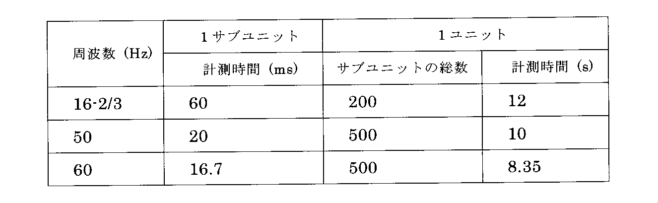
FIG. 4 is an explanatory diagram showing a specific example of the coupon current density calculation step. One subunit and one unit at each frequency Fb after the frequency Fb is specified can be set as shown in Table 1 below.
1ユニットの計測時間は、高速鉄道の通過によってパイプラインPに発生する交流腐食リスクを十分把握できるものでなくてはならない。高速鉄道とは、おもな区間を時速200km以上の速度で走行する列車やそのための路線を指しており、これは日本の新幹線の定義とも一致している。高速鉄道の車両の長さが25m、16両編成とすると1編成の長さは400mとなる。この高速鉄道は、時速200kmでクーポン電流密度の計測地点を通過するのに7.2秒を要することになる。よって、1ユニットの計測時間を8.35~12sに設定しておけば、どの周波数でも高速鉄道の通過によってパイプラインに発生する交流腐食リスクを十分把握できることになる。
∙ The measurement time for one unit must be able to sufficiently grasp the AC corrosion risk that occurs in the pipeline P due to the passage of the high-speed railway. A high-speed railway refers to a train that travels through a major section at a speed of 200 km / h or higher, and a route therefor, which matches the definition of the Japanese Shinkansen. If the length of the high-speed railway vehicle is 25 m and the 16-car train is set, the length of one train is 400 m. This high-speed railway requires 7.2 seconds to pass the coupon current density measurement point at a speed of 200 km / h. Therefore, if the measurement time of one unit is set to 8.35 to 12 s, it is possible to sufficiently grasp the AC corrosion risk generated in the pipeline due to the passage of the high-speed railway at any frequency.
図4(a)には、周波数Fbが16-2/3Hzに特定された場合のクーポン電流密度の算出例を示している。この場合は、表1に示したように、1サブユニットの計測時間は60msに設定され、1ユニットの計測時間は12sに設定されており、クーポン直流電流密度IDCとクーポン交流電流密度IACは下記(3),(4)式によって求められる。

FIG. 4A shows an example of calculating the coupon current density when the frequency Fb is specified as 16-2 / 3 Hz. In this case, as shown in Table 1, the measurement time of one subunit is set to 60 ms, the measurement time of one unit is set to 12 s, and the coupon DC current density I DC and the coupon AC current density I AC are set. Is obtained by the following equations (3) and (4).
図4(b)には、周波数Fbが60Hzに特定された場合のクーポン電流密度の算出例を示している。この場合は、表1に示したように、1サブユニットの計測時間は16.7msに設定され、1ユニットの計測時間は8.35sに設定されており、クーポン直流電流密度IDCとクーポン交流電流密度IACは下記(5),(6)式によって求められる。
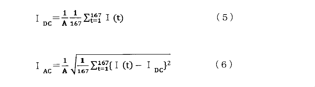
FIG. 4B shows an example of calculating the coupon current density when the frequency Fb is specified as 60 Hz. In this case, as shown in Table 1, the measurement time of one subunit is set to 16.7 ms, the measurement time of one unit is set to 8.35 s, and the coupon DC current density I DC and the coupon AC are set. The current density I AC is obtained by the following equations (5) and (6).
周波数Fbが50Hzに特定された場合のクーポン電流密度の算出例は、図1(b)に示したとおりであり、算出式は前述した(1),(2)式に示したとおりである。
A calculation example of the coupon current density when the frequency Fb is specified as 50 Hz is as shown in FIG. 1B, and the calculation formula is as shown in the above-described formulas (1) and (2).
図5は、本発明の一実施形態に係るパイプラインにおける交流腐食リスクの計測評価装置を示した説明図である。この計測評価装置10は、地中に埋設された金属製のパイプラインPにクーポンCを接続し、クーポン電流の計測値から求められるクーポン直流電流密度とクーポン交流電流密度によってパイプラインPの交流腐食リスクを評価する装置であって、周波数特定手段11とクーポン電流密度算出手段12を備えている。
FIG. 5 is an explanatory diagram showing an AC corrosion risk measurement / evaluation apparatus in a pipeline according to an embodiment of the present invention. This measurement / evaluation apparatus 10 connects a coupon C to a metal pipeline P buried in the ground, and the AC corrosion of the pipeline P is determined by the coupon DC current density and the coupon AC current density obtained from the measured value of the coupon current. It is an apparatus for evaluating risk, and includes a frequency specifying means 11 and a coupon current density calculating means 12.
周波数特定手段11は、携帯型PCやプログラマブルコントローラなどの制御装置によって構成することができ、クーポン電流密度算出手段12から得られるクーポン電流I(t)の計測値波形によって前述した周波数特定工程を実行するためのプログラムを備えている。周波数特定手段11によって特定された周波数がクーポン電流密度算出手段12に出力される。
The frequency specifying means 11 can be configured by a control device such as a portable PC or a programmable controller, and executes the above-described frequency specifying process by the measured value waveform of the coupon current I (t) obtained from the coupon current density calculating means 12. It has a program to do. The frequency specified by the frequency specifying unit 11 is output to the coupon current density calculating unit 12.
クーポン電流密度算出手段12は、前述したクーポン電流密度算出工程を実行するためのプログラムを備えており、周波数特定手段11によって特定された周波数から1サブユニットと1ユニットの計測時間が設定され、0.1msのサンプリング間隔で計測されるクーポン電流I(t)から1サブユニット毎にクーポン直流電流密度IDCとクーポン交流電流密度IACが算出され、1ユニット毎にIDC
ave,IDC
max,IDC
min,IAC
ave,IAC
max,IAC
minが求められる。
The coupon current density calculating unit 12 includes a program for executing the above-described coupon current density calculating step, and the measurement time of one subunit and one unit is set from the frequency specified by the frequency specifying unit 11, The coupon DC current density I DC and coupon AC current density I AC are calculated for each subunit from the coupon current I (t) measured at a sampling interval of 1 ms, and I DC ave , I DC max , I DC min , I AC ave , I AC max , and I AC min are obtained.
このような特徴を有するパイプラインにおける交流腐食リスクの計測評価方法或いはこの方法を実行するための計測評価装置10によると、計測されたクーポン電流I(t)によって交流腐食発生源の周波数を特定することができるので、特定された周波数に基づいて1サブユニットと1ユニットの計測時間がその都度設定されることになる。これによって、交流腐食リスクを評価するための指標となるクーポン直流電流密度IDCとクーポン交流電流密度IACを精緻な値で得ることができる。
According to the measurement and evaluation method of the AC corrosion risk in the pipeline having such characteristics or the measurement and evaluation apparatus 10 for executing this method, the frequency of the AC corrosion source is specified by the measured coupon current I (t). Therefore, the measurement time of one subunit and one unit is set each time based on the specified frequency. This makes it possible to obtain a coupon direct current density I DC coupon alternating current density I AC which is an index for evaluating the AC corrosion risk precise value.
これによると、如何なる地域で交流腐食リスクの計測評価を行う場合であっても、地域毎の商用交流周波数の違いを問題にすること無く、交流腐食リスクを評価するための指標となるクーポン直流電流密度IDCとクーポン交流電流密度IACを精緻な値で得ることができる。また、クーポン電流密度の計測地点で、交流腐食発生源を明確に特定できない場合や、異なる商用交流周波数を用いた交流腐食発生源の影響が混在している場合であっても、計測評価を行う際に交流腐食発生源の周波数を特定することができるので、特定された周波数に基づいてクーポン直流電流密度IDCとクーポン交流電流密度IACを精緻な値で得ることができる。
According to this, regardless of the area where AC corrosion risk is measured and evaluated, coupon DC current can be used as an index for evaluating AC corrosion risk without causing a difference in commercial AC frequency for each area. The density I DC and the coupon alternating current density I AC can be obtained with precise values. In addition, measurement evaluation is performed even when the source of AC corrosion cannot be clearly identified at the coupon current density measurement point, or even when the effects of AC corrosion sources using different commercial AC frequencies are mixed. In this case, since the frequency of the AC corrosion source can be specified, the coupon DC current density I DC and the coupon AC current density I AC can be obtained with precise values based on the specified frequency.
10:計測評価装置,
11:周波数特定手段,12:クーポン電流密度算出手段,
P:パイプライン,P1:コーティング,C:クーポン,W:電線,
Rs:シャント抵抗,M:計測装置 10: Measurement evaluation device,
11: Frequency specifying means, 12: Coupon current density calculating means,
P: Pipeline, P1: Coating, C: Coupon, W: Electric wire
Rs: Shunt resistance, M: Measuring device
11:周波数特定手段,12:クーポン電流密度算出手段,
P:パイプライン,P1:コーティング,C:クーポン,W:電線,
Rs:シャント抵抗,M:計測装置 10: Measurement evaluation device,
11: Frequency specifying means, 12: Coupon current density calculating means,
P: Pipeline, P1: Coating, C: Coupon, W: Electric wire
Rs: Shunt resistance, M: Measuring device
Claims (5)
- 地中に埋設された金属製のパイプラインにクーポンを接続し、クーポン電流の計測値から求められるクーポン直流電流密度とクーポン交流電流密度によってパイプラインの交流腐食リスクを評価する方法であって、
クーポン電流の計測値波形から交流腐食発生源の周波数を特定する周波数特定工程と、
特定された周波数の1周期を1単位時間として、当該1単位時間内のクーポン電流の計測値から1組のクーポン直流電流密度とクーポン交流電流密度を求めるクーポン電流密度算出工程を有し、
前記周波数特定工程は、
商用交流周波数である16-2/3Hz,50Hz,60Hzの中なら一つの周波数を順次選択して、選択した周波数の1周期でクーポン電流の計測値波形を切り出し、切り出した波形の最大値と最小値の出現時刻の差が選択した周波数の1周期の1/2と一致するか否かを判定し、当該判定の結果が一致する場合に、選択した周波数を交流腐食発生源の周波数として特定することを特徴とするパイプラインにおける交流腐食リスクの計測評価方法。 It is a method of connecting a coupon to a metal pipeline buried in the ground, and evaluating the AC corrosion risk of the pipeline by the coupon DC current density and the coupon AC current density obtained from the measured value of the coupon current,
A frequency identification process for identifying the frequency of the AC corrosion source from the measured value waveform of the coupon current;
A coupon current density calculation step for obtaining a set of coupon DC current density and coupon AC current density from a measured value of the coupon current within the one unit time with one cycle of the identified frequency as one unit time,
The frequency specifying step includes
If a commercial AC frequency is 16-2 / 3 Hz, 50 Hz, or 60 Hz, one frequency is selected sequentially, and the measured value waveform of the coupon current is extracted in one cycle of the selected frequency, and the maximum value and minimum value of the extracted waveform are extracted. It is determined whether or not the difference between the appearance times of the values is equal to ½ of one cycle of the selected frequency. If the result of the determination is the same, the selected frequency is specified as the frequency of the AC corrosion source. A method for measuring and evaluating AC corrosion risk in pipelines. - 前記1単位時間をサブユニットとして、当該サブユニットを複数連続させた1ユニットを設定し、前記サブユニット毎に求めたクーポン直流電流密度とクーポン交流電流密度を比較して前記1ユニット内での最大値,最小値を求め、当該最大値,最小値によってパイプラインの交流腐食リスクを評価することを特徴とする請求項1に記載されたパイプラインにおける交流腐食リスクの計測評価方法。 The unit time is set as a subunit, and one unit in which a plurality of the subunits are continuously set is set, and the coupon DC current density obtained for each subunit is compared with the coupon AC current density to obtain the maximum in the unit. The method for measuring and evaluating the AC corrosion risk in a pipeline according to claim 1, wherein the AC corrosion risk of the pipeline is evaluated based on the maximum and minimum values.
- 前記1ユニットの計測時間は、交流腐食発生源の周波数が16-2/3Hzであると特定された場合には12sに設定し、交流腐食発生源の周波数が50Hzであると特定された場合には10sに設定し、交流腐食発生源の周波数が60Hzであると特定された場合には8.35sに設定することを特徴とする請求項2に記載されたパイプラインにおける交流腐食リスクの計測評価方法。 The measurement time of the one unit is set to 12 s when the frequency of the AC corrosion source is specified to be 16-2 / 3 Hz, and when the frequency of the AC corrosion source is specified to be 50 Hz. Is set to 10 s, and is set to 8.35 s when the frequency of the source of AC corrosion generation is specified to be 60 Hz, measurement and evaluation of AC corrosion risk in a pipeline according to claim 2 Method.
- 前記クーポン電流の計測値波形は、0.1msのサンプリング間隔で計測されたクーポン電流の時系列データであることを特徴とする請求項1~3のいずれかに記載されたパイプラインにおける交流腐食リスクの計測評価方法。 The risk of AC corrosion in a pipeline according to any one of claims 1 to 3, wherein the measured value waveform of the coupon current is time-series data of a coupon current measured at a sampling interval of 0.1 ms. Measurement evaluation method.
- 地中に埋設された金属製のパイプラインにクーポンを接続し、クーポン電流の計測値から求められるクーポン直流電流密度とクーポン交流電流密度によってパイプラインの交流腐食リスクを評価する装置であって、
クーポン電流の計測値波形から交流腐食発生源の周波数を特定する周波数特定手段と、
特定された周波数の1周期を1単位時間として、当該1単位時間内のクーポン電流の計測値から1組のクーポン直流電流密度とクーポン交流電流密度を求めるクーポン電流密度算出手段とを有し、
前記周波数特定手段は、
商用交流周波数である16-2/3Hz,50Hz,60Hzの中から一つの周波数を順次選択して、選択した周波数の1周期でクーポン電流の計測値波形を切り出し、切り出した波形の最大値と最小値の出現時刻の差が選択した周波数の1周期の1/2と一致するか否かを判定し、当該判定の結果が一致する場合に、選択した周波数を交流腐食発生源の周波数として特定することを特徴とするパイプラインにおける交流腐食リスクの計測評価装置。 A device for connecting a coupon to a metal pipeline buried in the ground, and evaluating the AC corrosion risk of the pipeline by the coupon DC current density and the coupon AC current density obtained from the measured value of the coupon current,
Frequency identification means for identifying the frequency of the AC corrosion source from the measured value waveform of the coupon current;
One cycle of the identified frequency as one unit time, and a coupon current density calculating means for obtaining a set of coupon DC current density and coupon AC current density from the measured value of the coupon current within the one unit time,
The frequency specifying means includes
One frequency is sequentially selected from the commercial AC frequencies of 16-2 / 3 Hz, 50 Hz, and 60 Hz, and the measured value waveform of the coupon current is cut out in one cycle of the selected frequency, and the maximum and minimum values of the cut-out waveform are cut out. It is determined whether or not the difference between the appearance times of the values is equal to ½ of one cycle of the selected frequency. If the result of the determination is the same, the selected frequency is specified as the frequency of the AC corrosion source. This is a measurement and evaluation device for AC corrosion risk in pipelines.
Priority Applications (2)
| Application Number | Priority Date | Filing Date | Title |
|---|---|---|---|
| EP12853255.3A EP2799850B1 (en) | 2011-11-29 | 2012-06-04 | Pipeline ac corrosion risk measurement and evaluation method and measurement and evaluation device |
| US14/240,944 US9568412B2 (en) | 2011-11-29 | 2012-06-04 | Method and instrumentation for measuring and assessing AC corrosion risk of pipeline |
Applications Claiming Priority (2)
| Application Number | Priority Date | Filing Date | Title |
|---|---|---|---|
| JP2011-260861 | 2011-11-29 | ||
| JP2011260861A JP5586572B2 (en) | 2011-11-29 | 2011-11-29 | Method and apparatus for measuring and evaluating AC corrosion risk in pipelines |
Publications (1)
| Publication Number | Publication Date |
|---|---|
| WO2013080587A1 true WO2013080587A1 (en) | 2013-06-06 |
Family
ID=48535071
Family Applications (1)
| Application Number | Title | Priority Date | Filing Date |
|---|---|---|---|
| PCT/JP2012/064379 WO2013080587A1 (en) | 2011-11-29 | 2012-06-04 | Pipeline ac corrosion risk measurement and evaluation method and measurement and evaluation device |
Country Status (4)
| Country | Link |
|---|---|
| US (1) | US9568412B2 (en) |
| EP (1) | EP2799850B1 (en) |
| JP (1) | JP5586572B2 (en) |
| WO (1) | WO2013080587A1 (en) |
Families Citing this family (8)
| Publication number | Priority date | Publication date | Assignee | Title |
|---|---|---|---|---|
| US9804078B2 (en) * | 2013-07-01 | 2017-10-31 | Bass Corrosion Services, Inc. | Multiple coupon apparatus for cathodic protection testing |
| JP6030518B2 (en) * | 2013-08-20 | 2016-11-24 | 東京瓦斯株式会社 | Method for measuring cathodic protection of buried pipelines |
| JP6045524B2 (en) * | 2014-02-27 | 2016-12-14 | 東京瓦斯株式会社 | AC corrosion risk measurement evaluation method and measurement evaluation system for buried metal bodies |
| JP6259749B2 (en) * | 2014-10-14 | 2018-01-10 | 東京瓦斯株式会社 | AC corrosion risk measurement and evaluation method for buried metal bodies |
| CN111256051A (en) * | 2020-01-21 | 2020-06-09 | 厦门普为光电科技有限公司 | Optical communication lamp |
| US11598714B1 (en) * | 2021-06-17 | 2023-03-07 | Matergenics, Inc. | Alternating current interference corrosion detector |
| CN113981453B (en) * | 2021-09-10 | 2023-11-28 | 北京市燃气集团有限责任公司 | Method and device for evaluating risk of stray current corrosion of gas pipe network with cathode protection |
| CN115219823B (en) * | 2022-07-15 | 2024-01-30 | 北京市燃气集团有限责任公司 | Pipeline multipoint synchronous monitoring analysis method and device under railway dynamic alternating current interference |
Citations (4)
| Publication number | Priority date | Publication date | Assignee | Title |
|---|---|---|---|---|
| JP2002296213A (en) * | 2001-03-29 | 2002-10-09 | Osaka Gas Co Ltd | Corrosion evaluation method and database |
| JP2008281433A (en) * | 2007-05-10 | 2008-11-20 | Tokyo Gas Co Ltd | Method and apparatus for measuring/evaluating cathode corrosion condition of underground pipeline |
| JP2009156707A (en) * | 2007-12-26 | 2009-07-16 | Tokyo Gas Co Ltd | Measurement evaluation method and measurement evaluation system of cathode corrosion protection state |
| JP2011191288A (en) * | 2010-02-22 | 2011-09-29 | Jfe Engineering Corp | Method and device for estimating current density of damaged coating portion of underground pipe, and method and device for controlling electric protection |
Family Cites Families (6)
| Publication number | Priority date | Publication date | Assignee | Title |
|---|---|---|---|---|
| US5216370A (en) * | 1991-10-24 | 1993-06-01 | Corrpro Companies, Inc. | Method and system for measuring the polarized potential of a cathodically protected structures substantially IR drop free |
| JPH06288897A (en) | 1993-03-30 | 1994-10-18 | Tokyo Gas Co Ltd | Measuring method of ac component in conduct ground potential of soil-buried conduit |
| EP1571438A1 (en) * | 2004-03-01 | 2005-09-07 | MetriCorr ApS | A method and a system of diagnosing corrosion risk of a pipe or a pipeline in soil |
| JP5060052B2 (en) * | 2006-01-17 | 2012-10-31 | 東京瓦斯株式会社 | Anticorrosion management method, anticorrosion management device, anticorrosion management program, information recording medium of buried metal body cathodically protected |
| JP4767145B2 (en) * | 2006-10-16 | 2011-09-07 | 東京瓦斯株式会社 | Cathodic protection system and cathodic protection method by galvanic anode method, pipeline soundness evaluation system and soundness evaluation method |
| US20110238347A1 (en) * | 2010-03-24 | 2011-09-29 | Elecsys Corporation | Apparatus and system for automated pipeline testing |
-
2011
- 2011-11-29 JP JP2011260861A patent/JP5586572B2/en active Active
-
2012
- 2012-06-04 US US14/240,944 patent/US9568412B2/en active Active
- 2012-06-04 EP EP12853255.3A patent/EP2799850B1/en active Active
- 2012-06-04 WO PCT/JP2012/064379 patent/WO2013080587A1/en active Application Filing
Patent Citations (4)
| Publication number | Priority date | Publication date | Assignee | Title |
|---|---|---|---|---|
| JP2002296213A (en) * | 2001-03-29 | 2002-10-09 | Osaka Gas Co Ltd | Corrosion evaluation method and database |
| JP2008281433A (en) * | 2007-05-10 | 2008-11-20 | Tokyo Gas Co Ltd | Method and apparatus for measuring/evaluating cathode corrosion condition of underground pipeline |
| JP2009156707A (en) * | 2007-12-26 | 2009-07-16 | Tokyo Gas Co Ltd | Measurement evaluation method and measurement evaluation system of cathode corrosion protection state |
| JP2011191288A (en) * | 2010-02-22 | 2011-09-29 | Jfe Engineering Corp | Method and device for estimating current density of damaged coating portion of underground pipe, and method and device for controlling electric protection |
Non-Patent Citations (2)
| Title |
|---|
| "Handbook of Stray Current Control and Cathodic Protection", 20 January 2011, OHMSHA, LTD., pages: 123 - 156 |
| W. V. BAECKMANN; W. SCHWENK: "Handbuch des kathodischen Korrosionsschutzes", 1999, WILEY-VCH VERLAG GMBH |
Also Published As
| Publication number | Publication date |
|---|---|
| JP2013113742A (en) | 2013-06-10 |
| EP2799850B1 (en) | 2017-10-25 |
| US9568412B2 (en) | 2017-02-14 |
| US20140225631A1 (en) | 2014-08-14 |
| JP5586572B2 (en) | 2014-09-10 |
| EP2799850A4 (en) | 2015-07-08 |
| EP2799850A1 (en) | 2014-11-05 |
Similar Documents
| Publication | Publication Date | Title |
|---|---|---|
| WO2013080587A1 (en) | Pipeline ac corrosion risk measurement and evaluation method and measurement and evaluation device | |
| JP4812687B2 (en) | Method and apparatus for measuring and evaluating cathodic protection of buried pipelines | |
| RU2539830C2 (en) | Method for determining place of damage in air and cable lines of power transmission in networks with insulated neutral | |
| KR20150059089A (en) | The method and apparatus for locating the udnePinpointing the earth leaking point under TN-C environment | |
| CN104233314A (en) | Dynamic interference potential test system for buried pipeline | |
| Mujezinović et al. | Estimating harmful effect of dynamic stray currents on pipeline by simultaneous multiparametric field measurements, continuous wavelet cross‐correlation analysis, and frequency plots | |
| RU2014106435A (en) | METHOD FOR DETERMINING THE SHORT-TERMINAL PLACES OF THE ELECTRIFIED TRANSPORT CONTACT NETWORK | |
| Kolář et al. | Measurement of ground currents leaking from DC electric traction | |
| Mariscotti et al. | Resistance and internal inductance of traction rails at power frequency: A survey | |
| JP6030518B2 (en) | Method for measuring cathodic protection of buried pipelines | |
| JP5231899B2 (en) | Cathodic protection method for pipelines | |
| RU2529566C1 (en) | Method to measure asymmetry of alternating traction current in rail lines under alss coils | |
| TW211067B (en) | ||
| JP4974300B2 (en) | High resistance ground fault detection method and apparatus | |
| ATE489637T1 (en) | METHOD FOR DETERMINING ELECTRICAL PARAMETERS OF A SECTION OF A MAGNETIC TRAIN | |
| JP6045524B2 (en) | AC corrosion risk measurement evaluation method and measurement evaluation system for buried metal bodies | |
| Kolář et al. | Measurement of current flowing through a rail with the use of Ohm’s method; determination of the impedance of a rail | |
| JP6338722B1 (en) | Measurement and evaluation method for DC stray current corrosion risk | |
| Wang et al. | A Systematic Approach for AC Electromagnetic Interference Study between Railways and Nearby Power Lines | |
| RU2576359C2 (en) | Method of resistance determination of catenary and rail systems of railroad transport | |
| JP2004294353A (en) | Device for detecting plate thickness for hollow metallic body | |
| Siranec et al. | Measurement and Evaluation of the Stray Currents from the AC Electric Traction Systems | |
| Faria | The effect of power-line sagged conductors on the evaluation of the differential voltage in a nearby circuit at ground level | |
| Sokolov et al. | Approbation of the State of Track Circuit Data Processing Method in Intelligent Systems of Control and Diagnosis | |
| Kolář et al. | Simulation and measurement of selected electrical parameters for electric drainage |
Legal Events
| Date | Code | Title | Description |
|---|---|---|---|
| 121 | Ep: the epo has been informed by wipo that ep was designated in this application |
Ref document number: 12853255 Country of ref document: EP Kind code of ref document: A1 |
|
| WWE | Wipo information: entry into national phase |
Ref document number: 14240944 Country of ref document: US |
|
| REEP | Request for entry into the european phase |
Ref document number: 2012853255 Country of ref document: EP |
|
| WWE | Wipo information: entry into national phase |
Ref document number: 2012853255 Country of ref document: EP |
|
| NENP | Non-entry into the national phase |
Ref country code: DE |