JP2005291942A - Rotation angle sensor - Google Patents
Rotation angle sensor Download PDFInfo
- Publication number
- JP2005291942A JP2005291942A JP2004107910A JP2004107910A JP2005291942A JP 2005291942 A JP2005291942 A JP 2005291942A JP 2004107910 A JP2004107910 A JP 2004107910A JP 2004107910 A JP2004107910 A JP 2004107910A JP 2005291942 A JP2005291942 A JP 2005291942A
- Authority
- JP
- Japan
- Prior art keywords
- magnetic
- rotation angle
- angle sensor
- magnetism
- sensor
- Prior art date
- Legal status (The legal status is an assumption and is not a legal conclusion. Google has not performed a legal analysis and makes no representation as to the accuracy of the status listed.)
- Withdrawn
Links
- 230000002093 peripheral effect Effects 0.000 claims abstract description 15
- 230000004907 flux Effects 0.000 claims abstract description 13
- 230000005389 magnetism Effects 0.000 claims description 45
- 238000006073 displacement reaction Methods 0.000 abstract description 4
- 238000005259 measurement Methods 0.000 description 7
- 230000000052 comparative effect Effects 0.000 description 5
- 239000000696 magnetic material Substances 0.000 description 5
- 229910001172 neodymium magnet Inorganic materials 0.000 description 5
- 238000000034 method Methods 0.000 description 3
- 230000000694 effects Effects 0.000 description 1
- 238000004519 manufacturing process Methods 0.000 description 1
- 238000005096 rolling process Methods 0.000 description 1
Images

Landscapes
- Transmission And Conversion Of Sensor Element Output (AREA)
Abstract
Description
本発明は軸ずれによって生じる角度誤差を低減可能な回転角度センサに関するものである。 The present invention relates to a rotation angle sensor capable of reducing an angle error caused by an axis deviation.
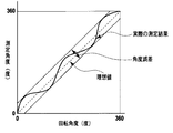
回転角度センサにおける角度誤差は、図1に示すように表すことができる。すなわち、図1に示すように、横軸は回転角度センサの回転角度であり、縦軸は当該回転角度センサによる測定値である測定角度である。回転角度センサの回転角度に、当該回転角度センサによる測定値である測定角度が全回転角度において正確に一致していれば、図1に点線で示すような理想値直線が得られるが、実際の測定結果を示す実線は、理想値直線からはなれるほど、測定誤差が大きいことを示しており、+側(実際の回転角度より測定角度の方が大きい)の最大誤差(絶対値)と、−側(実際の回転角度より測定角度の方が小さい)の最大誤差(絶対値)との合計を角度誤差と定義することができる。 The angle error in the rotation angle sensor can be expressed as shown in FIG. That is, as shown in FIG. 1, the horizontal axis is the rotation angle of the rotation angle sensor, and the vertical axis is the measurement angle that is a measurement value by the rotation angle sensor. If the rotation angle of the rotation angle sensor exactly matches the measurement angle measured by the rotation angle sensor at all rotation angles, an ideal value straight line as shown by a dotted line in FIG. 1 can be obtained. The solid line indicating the measurement result indicates that the measurement error is larger the farther from the ideal value line, the maximum error (absolute value) on the + side (the measurement angle is larger than the actual rotation angle), and − The sum of the maximum error (absolute value) on the side (the measured angle is smaller than the actual rotation angle) can be defined as the angle error.
軸ずれによって生じる角度誤差を低減する従来の回転角度センサとして以下のような技術が知られている。 The following technique is known as a conventional rotation angle sensor that reduces an angle error caused by an axis deviation.
まず、特許文献1においては、変形ベアリングの内輪をテーパ状に形成し、この内輪に固定された回転軸と共に磁石が回転して、磁石の円周直下に近接させて配置された磁気センサから、角度変化に対応した出力が得られるようになっている。回転軸および磁石の自重により、変形ベアリングの内輪が外輪の内側側面に向けて転動体を押し付ける力が働くので、回転軸が横方向の力による影響を受けにくくなり、回転軸の横ずれによる角度測定の誤差を小さくすることができるものである。
First, in
また、特許文献2においては、円板状に形成された磁石は、回転軸に支持されており、この回転軸と共に回転中心線を中心として円周方向に回転する。磁石の円周付近に配置された4つの磁気センサは、磁石の円板面に平行な平面P上に固定されている。1対の磁気センサが平面P上の基準点Oに対称的に配置され、他の1対の磁気センサが基準点Oに対称的に配置されている。平面Pと磁石の回転中心線との交点とほぼ一致する基準点Oから各磁気センサの中心までの距離は、磁石の半径と異なっているというものである。
Moreover, in
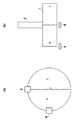
さらに、特許文献3においては、センサ全体のサイズをより小さくし、かつ性能の安定性が良い回転角度センサを提供することを目的としたものであって、図2の(a),(b)に示すように、円板状に形成された磁石1は回転軸2に支持され、この回転軸2を中心として、回転可能に構成された回転角度センサが記載されている。磁気センサAおよびBは、共に等しい温度特性を有するホール素子であり、円板の中心Oと磁気センサAとを通る直線、および中心Oと磁気センサBとを通る直線とがなす角度が概ね90度になるように配置されている。また、磁気センサAおよびBは、共に磁石の円周の直下に配置されている。
Further,
特許文献3の構造を有する回転角度センサには、特許文献1に記述されているように、軸ずれにより角度精度が低下するという問題があった。特許文献1に開示されている技術を用いれば内輪と外輪がテーパ状に形成された変形ベアリングを用いてケース本体を構成することによって軸ずれによる角度誤差を低減することが出来るが、回転角度センサ専用のケースを用いない場合や非接触で回転角度を測定できるという特長を活かして、円盤型磁石と磁気センサ等が配置されているセンサ部が異なるケースに封入されている場合は特許文献1による方法により軸ずれによる角度精度の低下を改善することが出来ない。
As described in
通常、径方向着磁した円盤型磁石が生成するZ軸方向の磁束密度は、図3に示すように、磁石の最端部付近が最大となるため、良好な分解能や外来磁場の影響を最小限にするために、磁気センサはこの磁石の端部付近に設置される。しかしながら、この磁石端部付近の磁束密度は、磁石の径方向の位置の変化に対する磁束密度の変化率が非常に大きいため軸ずれにより磁気センサが検出する磁束密度が大きく変化し、結果として大きな角度誤差を生ずることとなる。特許文献2に記載のセンサではこの問題は解消できない。
Normally, the magnetic flux density in the Z-axis direction generated by a radially magnetized disk-type magnet is maximized near the end of the magnet as shown in FIG. In order to limit, the magnetic sensor is installed near the end of the magnet. However, the magnetic flux density near the end of the magnet has a very large change rate of the magnetic flux density with respect to the change in the radial position of the magnet, so that the magnetic flux density detected by the magnetic sensor greatly changes due to the axis deviation, resulting in a large angle. An error will occur. This problem cannot be solved by the sensor described in
そこで本発明の目的は以上のような問題を解消し、回転角度センサのケース本体の構造に依らずに軸ずれによる角度誤差を低減することができる回転角度センサを提供することにある。 SUMMARY OF THE INVENTION Accordingly, an object of the present invention is to provide a rotation angle sensor that solves the above-described problems and can reduce an angle error due to an axis deviation without depending on the structure of the case body of the rotation angle sensor.
発明者は、磁気発生部の形状を所定の断面形状にすることによって、磁気発生部の端部での磁束密度変化が緩和出来ることを見出し、ケース本体有無に依らずに軸ずれによる角度誤差を低減することが出来ることを見出した。 The inventor has found that the magnetic flux density change at the end of the magnetism generating portion can be reduced by making the shape of the magnetism generating portion a predetermined cross-sectional shape. It was found that it can be reduced.
本発明は上記知見に基づいてなされたものであって、回転軸線を含む平面上の断面形状が当該回転軸の周りの全周で等しい磁気発生部と、前記前記磁気発生部の回転軸を中心とする回転により生じる磁束密度の変化を検出する複数の磁気センサと、からなる回転角度センサにおいて、前記磁気発生部の前記磁気センサに対向する部分は、周辺部分の方がその他の部分よりも前記磁気センサとの間の距離が大になるように構成されていることを特徴とする。 The present invention has been made on the basis of the above-described knowledge, and a magnetism generating section having a cross-sectional shape on a plane including a rotation axis is the same around the entire circumference of the rotation axis, and the rotation axis of the magnetism generation section is the center. And a rotation angle sensor comprising a plurality of magnetic sensors for detecting a change in magnetic flux density caused by the rotation, wherein the portion of the magnetism generator that faces the magnetic sensor has a peripheral portion that is more than the other portions. The distance between the magnetic sensor and the magnetic sensor is large.
ここで、前記磁気発生部の前記磁気センサに対向する部分は、当該磁気発生部の周縁に向かって傾斜または曲面が形成されていることとすることができる。 Here, the portion of the magnetism generating portion that faces the magnetic sensor may be inclined or curved toward the periphery of the magnetism generating portion.
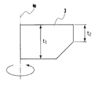
また、前記回転軸線を含む平面上の断面における、前記磁気発生部の最大厚さt1と周辺部の厚さt2がt1>t2となっていることとすることができる。 Further, the maximum thickness t1 of the magnetism generating portion and the thickness t2 of the peripheral portion in a cross section on a plane including the rotation axis may be t1> t2.
さらに、前記断面の最大厚さt1と前記周辺部の厚さt2がt1>t2≧0.5×t1となっていることとすることができる。 Furthermore, the maximum thickness t1 of the cross section and the thickness t2 of the peripheral portion may be t1> t2 ≧ 0.5 × t1.
さらに、前記磁気発生部の前記磁気センサに対向する部分は、前記周辺部の傾斜または曲線の平均線とその他の部分との間の角度が0.5度以上45度以下であることとすることができる。 Further, in the portion of the magnetism generation portion facing the magnetic sensor, the angle between the slope of the peripheral portion or the average line of the curve and the other portion is not less than 0.5 degrees and not more than 45 degrees. Can do.
さらに、前記磁気発生部の前記磁気センサに対向する部分は、段差が形成されていることとすることができる。 Furthermore, a step may be formed in a portion of the magnetism generating portion that faces the magnetic sensor.
さらに、前記段差は、半径が異なる円板を積層して形成されていることとすることができる。 Further, the step may be formed by stacking discs having different radii.
本発明によれば、磁気発生部と複数の磁気センサから構成される回転角度センサにおいて、ケース本体の構造に依存することなく、軸ずれによって生ずる角度誤差を低減することができる。これにより、磁気センサ等の電気部品と磁石等の機械部品がそれぞれ異なるケースに封入されたような場合でも軸ずれによる角度誤差を低減した回転角度センサが得られる。 According to the present invention, in a rotation angle sensor composed of a magnetism generation unit and a plurality of magnetic sensors, an angle error caused by an axis deviation can be reduced without depending on the structure of the case body. Thereby, even when electrical parts such as a magnetic sensor and mechanical parts such as magnets are sealed in different cases, a rotation angle sensor can be obtained in which the angle error due to the axis deviation is reduced.
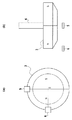
図4は本発明にかかる回転角度センサの基本構造の一例を示すものであって、(a)は磁気発生部の底面図、(b)は磁気発生部の側面図であり、磁気発生部3と磁気センサ4,5との間の位置関係も示してある。すなわち、回転軸線を含む平面上の断面形状が当該回転軸の周りの全周で等しい磁気発生部の一例としての、円板状に形成された永久磁石を含む磁気発生部3は、径方向に着磁されており、また、回転軸6に支持され、この回転軸6を中心として回転する。磁気センサ4および5は、例えばホール素子からなり、共に磁気発生部3の周辺部の直下に配置されており、且つ、(a)に示すように、磁気発生部3の円の中心Oと磁気センサ4とを通る直線、および中心Oと磁気センサ5とを通る直線とがなす角度が概ね90度になるように配置されている。さらに、磁気発生部3の磁気センサ4,5に対向する部分は、周辺部分の方がその他の部分よりも磁気センサ4,5との間の距離が大になるように構成されている。このように構成されているので、軸ずれが生じても、磁気発生部3の端部での磁束密度変化が緩和される。そのため、例えば、回転角度センサを収容するケース本体の構造に依らずに軸ずれによる角度誤差を低減することが出来る。
4A and 4B show an example of the basic structure of the rotation angle sensor according to the present invention, in which FIG. 4A is a bottom view of the magnetism generator, FIG. 4B is a side view of the magnetism generator, and
なお、磁気発生部3の構成は、磁気発生部の磁気センサに対向する部分に、当該磁気発生部の周縁に向かって傾斜または曲面を形成することによって実現することができる。その具体例を図5に示す。図5に示すように、回転軸を含む断面における、磁気発生部3の最大厚さt1と最外周部の厚さt2との間の関係はt1>t2となっている。例えば、磁気発生部が均一な磁石から構成されている場合、断面の最大厚さt1に比して最外周部の厚さt2が小さい磁気発生部は、断面の最大厚さt1と周辺部の厚さt2が同じである(t1=t2)磁気発生部より体積が減少することによって磁束密度が低下し回転角度センサの分解能や本来の角度精度が劣化する。また、外部磁場による角度誤差の影響も大きくなるので、概ね、t2の値はt1の値の1/4以上であることが好ましく、さらには1/2以上であることが一層好ましい。
In addition, the structure of the
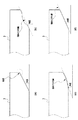
また、磁気発生部3の形状は機械的加工が容易で量産時の安定性が良い形状であれば良く、当該磁気発生部の磁気センサに対向する部分の一例としての、傾斜を構成する部分の形状は、図6の(a),(b),(c),(d)に例示するように、直線でも曲線でも良い。また、直線と曲線を併用しても良く、複数の変曲点を持つ曲線でも良い。前記周辺部の傾斜または曲線の平均線とその他の部分との間の角度は0.5度以上45度以下であることが好ましい。前記角度が大きくなると磁束密度の変化が急峻になるため所期の目的とする効果を得ることが出来ない。従って、この角度は制限を受け、概ね0.5度から45度の範囲内にすることが好ましく、さらには、9度から30度の範囲内であることがより好ましい。
The shape of the
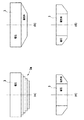
さらに、磁気発生部3の構成は、その全てを磁石によって構成してもよく、磁石と磁性体の組み合わせによって構成しても良い。図7の(a),(b),(c),(d)にその各例を示す。磁石と磁性体の組み合わせによって断面形状を構成する場合は、磁石が生成する磁束が磁性体内だけを通過し、磁気センサを通過しないような「閉磁気回路」にならないようにすることが肝要である。なお、(a)は、半径が異なる磁性体の円板3aを積層して、磁気発生部3の磁気センサに対向する部分に、段差を形成したものである。
Further, the configuration of the
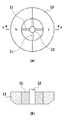
さらに、図7の(a)〜(d)は、回転軸線を含む平面上の断面形状が当該回転軸の周りの全周で等しい磁気発生部として、円板上の磁気発生部の構成の各例を示したが、回転軸線を含む平面上の断面形状が当該回転軸の周りの全周で等しい磁気発生部の他の例としては、図8に示すようなリング状の構造の磁気発生部であっても良い。図8の(a)は、リング状の磁気発生部13の平面図、(b)は、そのA−A断面図であり、リング状の磁気発生部13は、永久磁石で構成され、径方向に着磁され、磁性体または非磁性体からなる4個の支持部材11によって回転軸12に固定されている。
Further, (a) to (d) of FIG. 7 show each of the configurations of the magnetic generator on the disk as a magnetic generator having a cross-sectional shape on the plane including the rotation axis that is the same all around the rotation axis. Although an example has been shown, another example of the magnetic generator having the same cross-sectional shape on the plane including the rotation axis on the entire circumference around the rotation axis is as shown in FIG. It may be. FIG. 8A is a plan view of the ring-shaped
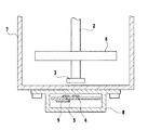
なお、磁気発生部と磁気センサ(センサ回路基板)とが異なるケースに収容されている例を図9に示す。6は回転軸2に固定されたギアであり、回転軸2の下端には磁気発生部3が取り付けられており、これらはギアケース7内に収容されている。このギアケース7の下にはセンサケース8が設けられており、このセンサケース8内にはセンサ回路基板9が収容されており、このセンサ回路基板9上に磁気センサ4,5が取り付けられている。このような構成においても、回転軸の軸ずれによる角度誤差は最小に抑えられる。
FIG. 9 shows an example in which the magnetism generation unit and the magnetic sensor (sensor circuit board) are accommodated in different cases.
以下に本発明の実施例を比較例(従来例)とともに説明する。
(比較例)
まず、比較例として、次の条件で回転角度センサを構成した。
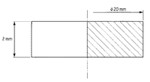
磁石(磁気発生部):ネオジウム磁石20mmΦ 厚み2mmt(図10)
磁気センサ:ホール素子(2個)
磁気センサと磁石底面との距離:1.0mm
なお、磁石とホール素子との位置関係は図2の通りである。このような構成の比較回転角度センサによる各軸ずれ量(mm)と、各軸ずれ量のときに磁気センサによって測定された角度誤差(±角度)との関係を調べた。
Examples of the present invention will be described below together with comparative examples (conventional examples).
(Comparative example)
First, as a comparative example, a rotation angle sensor was configured under the following conditions.
Magnet (magnetic generating part):
Magnetic sensor: Hall element (2 pieces)
Distance between magnetic sensor and magnet bottom: 1.0mm
The positional relationship between the magnet and the Hall element is as shown in FIG. The relationship between each axis deviation amount (mm) by the comparative rotation angle sensor having such a configuration and the angle error (± angle) measured by the magnetic sensor at each axis deviation amount was examined.
(実施例1)
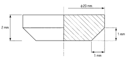
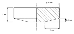
ついで、本発明の実施例1として、次の条件で回転角度センサを構成した。磁気発生部の断面形状(寸法)は図10の通りであり、全てを磁石で構成した。
磁石(磁気発生部):ネオジウム磁石20mmΦ 厚み2mmt(図11)
磁気センサ:ホール素子(2個)
磁気センサと磁石底面(傾斜部以外の平面)との距離:1.0mm
(Example 1)
Next, as Example 1 of the present invention, a rotation angle sensor was configured under the following conditions. The cross-sectional shape (dimensions) of the magnetism generating part is as shown in FIG. 10, and all were composed of magnets.
Magnet (magnetic generation part):
Magnetic sensor: Hall element (2 pieces)
Distance between magnetic sensor and magnet bottom (plane other than inclined part): 1.0 mm
なお、磁石とホール素子との位置関係は図4の通りである。このような構成の本発明回転角度センサ1による各軸ずれ量(mm)と、各軸ずれ量のときに磁気センサによって測定された角度誤差(±角度)との関係を調べた。
The positional relationship between the magnet and the Hall element is as shown in FIG. The relationship between each axis deviation amount (mm) by the
(実施例2)
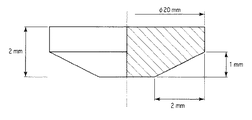
ついで、本発明の実施例2として、次の条件で回転角度センサを構成した。磁気発生部の断面形状(寸法)は図11の通りであり、全てを磁石で構成した。
磁石(磁気発生部):ネオジウム磁石20mmΦ 厚み2mmt(図12)
磁気センサ:ホール素子(2個)
磁気センサと磁石底面(傾斜部以外の平面)との距離:1.0mm
なお、磁石とホール素子との位置関係は図4の通りである。このような構成の本発明回転角度センサ2による各軸ずれ量(mm)と、各軸ずれ量のときに磁気センサによって測定された角度誤差(±角度)との関係を調べた。
(Example 2)
Next, as Example 2 of the present invention, a rotation angle sensor was configured under the following conditions. The cross-sectional shape (dimensions) of the magnetism generating part is as shown in FIG. 11, and all were composed of magnets.
Magnet (magnetic generating part):
Magnetic sensor: Hall element (2 pieces)
Distance between magnetic sensor and magnet bottom (plane other than inclined part): 1.0 mm
The positional relationship between the magnet and the Hall element is as shown in FIG. The relationship between each axis deviation amount (mm) by the
(実施例3)
ついで、本発明の実施例3として、次の条件で回転角度センサを構成した。磁気発生部の断面形状(寸法)は図12の通りであり、全てを磁石で構成した。
磁石(磁気発生部):ネオジウム磁石20mmΦ 厚み2mmt(図13)
磁気センサ:ホール素子(2個)
磁気センサと磁石底面(傾斜部以外の平面)との距離:1.0mm
なお、磁石とホール素子との位置関係は図4の通りである。このような構成の本発明回転角度センサ3による各軸ずれ量(mm)と、各軸ずれ量のときに磁気センサによって測定された角度誤差(±角度)との関係を調べた。
(Example 3)
Next, as Example 3 of the present invention, a rotation angle sensor was configured under the following conditions. The cross-sectional shape (dimensions) of the magnetism generating part is as shown in FIG. 12, and all were composed of magnets.
Magnet (magnet generation part): Neodymium magnet 20mmΦ Thickness 2mmt (Fig. 13)
Magnetic sensor: Hall element (2 pieces)
Distance between magnetic sensor and magnet bottom (plane other than inclined part): 1.0 mm
The positional relationship between the magnet and the Hall element is as shown in FIG. The relationship between each axis deviation amount (mm) by the
(実施例4)
ついで、本発明の実施例4として、次の条件で回転角度センサを構成した。磁気発生部の断面形状(寸法)は図12の通りであり、全てを磁石で構成した。
磁石(磁気発生部):ネオジウム磁石20mmΦ 厚み2mmt(図14)
磁気センサ:ホール素子(2個)
磁気センサと磁石底面(傾斜部以外の平面)との距離:1.0mm
Example 4
Next, as Example 4 of the present invention, a rotation angle sensor was configured under the following conditions. The cross-sectional shape (dimensions) of the magnetism generating part is as shown in FIG. 12, and all were composed of magnets.
Magnet (magnetic generating part):
Magnetic sensor: Hall element (2 pieces)
Distance between magnetic sensor and magnet bottom (plane other than inclined part): 1.0 mm
なお、磁石とホール素子との位置関係は図4の通りである。このような構成の本発明回転角度センサ4による各軸ずれ量(mm)と、各軸ずれ量のときに磁気センサによって測定された角度誤差(±角度)との関係を調べた。
The positional relationship between the magnet and the Hall element is as shown in FIG. The relationship between each axis deviation amount (mm) by the
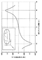
以上の比較回転角度センサと、本発明回転角度センサ1〜4の各軸ずれ量と角度誤差とを表1にまとめて示す。
Table 1 summarizes the amounts of axial misalignment and angle errors of the comparative rotation angle sensor and the

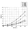
表1に示すように、本発明によれば、角度誤差が効果的に抑えられていることが明らかである。なお、以上の関係をグラフにして図15に示す。 As shown in Table 1, according to the present invention, it is clear that the angle error is effectively suppressed. The above relationship is shown as a graph in FIG.
本発明の応用例は、例えば、スロットルポジションセンサやモーターや手動動力によってギア位置を切り替える、2WD−4WD切替器やオートマチックシフト切替器などの回転位置センサに適用できる。 The application example of the present invention can be applied to a rotational position sensor such as a 2WD-4WD switch or an automatic shift switch that switches a gear position by a throttle position sensor, a motor, or manual power, for example.
2 回転軸
3 磁気発生部
4,5 磁気センサ
2 Rotating
Claims (7)
前記磁気発生部の前記磁気センサに対向する部分は、周辺部分の方がその他の部分よりも前記磁気センサとの間の距離が大になるように構成されていることを特徴とする回転角度センサ。 A magnetism generating section having a cross-sectional shape on a plane including the rotation axis is the same all around the rotation axis, and a plurality of magnetic sensors for detecting a change in magnetic flux density caused by rotation about the rotation axis of the magnetism generation section In the rotation angle sensor consisting of
The rotation angle sensor is characterized in that the portion of the magnetism generation portion facing the magnetic sensor is configured such that the distance between the peripheral portion and the magnetic sensor is greater than the other portion. .
The rotation angle sensor according to claim 6, wherein the step is formed by stacking discs having different radii.
Priority Applications (1)
| Application Number | Priority Date | Filing Date | Title |
|---|---|---|---|
| JP2004107910A JP2005291942A (en) | 2004-03-31 | 2004-03-31 | Rotation angle sensor |
Applications Claiming Priority (1)
| Application Number | Priority Date | Filing Date | Title |
|---|---|---|---|
| JP2004107910A JP2005291942A (en) | 2004-03-31 | 2004-03-31 | Rotation angle sensor |
Publications (1)
| Publication Number | Publication Date |
|---|---|
| JP2005291942A true JP2005291942A (en) | 2005-10-20 |
Family
ID=35325027
Family Applications (1)
| Application Number | Title | Priority Date | Filing Date |
|---|---|---|---|
| JP2004107910A Withdrawn JP2005291942A (en) | 2004-03-31 | 2004-03-31 | Rotation angle sensor |
Country Status (1)
| Country | Link |
|---|---|
| JP (1) | JP2005291942A (en) |
Cited By (12)
| Publication number | Priority date | Publication date | Assignee | Title |
|---|---|---|---|---|
| JP2009281978A (en) * | 2008-05-26 | 2009-12-03 | Asahi Kasei Electronics Co Ltd | Rotation angle sensor |
| JPWO2008050581A1 (en) * | 2006-10-26 | 2010-02-25 | 古河電気工業株式会社 | Rotation angle detector |
| JP2010066203A (en) * | 2008-09-12 | 2010-03-25 | Mitsubishi Electric Corp | Position detector of movable part, and two-degree-of-freedom actuator |
| DE112010003574T5 (en) | 2009-09-08 | 2012-10-04 | Ntn Corp. | Rotational angle detecting sensor |
| KR20150100746A (en) * | 2012-12-21 | 2015-09-02 | 알레그로 마이크로시스템스, 엘엘씨 | Magnetic field sensor arrangements and associated methods |
| CN104976949A (en) * | 2014-04-14 | 2015-10-14 | 罗伯特·博世有限公司 | Measuring Device For Contactless Determination Of Angle Of Rotation |
| JP2017161470A (en) * | 2016-03-11 | 2017-09-14 | Tdk株式会社 | Rotation angle detection device |
| JP2017161471A (en) * | 2016-03-11 | 2017-09-14 | Tdk株式会社 | Rotation angle detection device and rotary machine device |
| JP2018063209A (en) * | 2016-10-14 | 2018-04-19 | ミネベアミツミ株式会社 | Absolute encoder |
| CN113390440A (en) * | 2020-03-11 | 2021-09-14 | 深圳绿米联创科技有限公司 | Method, device and storage medium for detecting position state of target object |
| US11150125B2 (en) | 2017-06-07 | 2021-10-19 | Aisan Kogyo Kabushiki Kaisha | Method for producing remaining fuel detection device and fuel supply module |
| JP2024003378A (en) * | 2022-06-27 | 2024-01-15 | 内山工業株式会社 | detection device |
-
2004
- 2004-03-31 JP JP2004107910A patent/JP2005291942A/en not_active Withdrawn
Cited By (20)
| Publication number | Priority date | Publication date | Assignee | Title |
|---|---|---|---|---|
| JPWO2008050581A1 (en) * | 2006-10-26 | 2010-02-25 | 古河電気工業株式会社 | Rotation angle detector |
| JP2009281978A (en) * | 2008-05-26 | 2009-12-03 | Asahi Kasei Electronics Co Ltd | Rotation angle sensor |
| JP2010066203A (en) * | 2008-09-12 | 2010-03-25 | Mitsubishi Electric Corp | Position detector of movable part, and two-degree-of-freedom actuator |
| DE112010003574T5 (en) | 2009-09-08 | 2012-10-04 | Ntn Corp. | Rotational angle detecting sensor |
| US8896297B2 (en) | 2009-09-08 | 2014-11-25 | Ntn Corporation | Rotating angle detecting sensor |
| DE112010003574B4 (en) | 2009-09-08 | 2024-09-19 | Ntn Corp. | Rotation angle detection sensor |
| KR20150100746A (en) * | 2012-12-21 | 2015-09-02 | 알레그로 마이크로시스템스, 엘엘씨 | Magnetic field sensor arrangements and associated methods |
| KR102176106B1 (en) | 2012-12-21 | 2020-11-09 | 알레그로 마이크로시스템스, 엘엘씨 | Sensor for sensing a movement of an object and method of sensing a movement of an object |
| CN104976949A (en) * | 2014-04-14 | 2015-10-14 | 罗伯特·博世有限公司 | Measuring Device For Contactless Determination Of Angle Of Rotation |
| CN107179045A (en) * | 2016-03-11 | 2017-09-19 | Tdk株式会社 | Rotation angle detection apparatus and rotation mechanism |
| CN107179094A (en) * | 2016-03-11 | 2017-09-19 | Tdk株式会社 | Rotation angle detection apparatus |
| CN107179094B (en) * | 2016-03-11 | 2019-12-17 | Tdk株式会社 | Rotation angle detecting device |
| US10775195B2 (en) | 2016-03-11 | 2020-09-15 | Tdk Corporation | Rotation angle sensing device |
| JP2017161471A (en) * | 2016-03-11 | 2017-09-14 | Tdk株式会社 | Rotation angle detection device and rotary machine device |
| JP2017161470A (en) * | 2016-03-11 | 2017-09-14 | Tdk株式会社 | Rotation angle detection device |
| JP2018063209A (en) * | 2016-10-14 | 2018-04-19 | ミネベアミツミ株式会社 | Absolute encoder |
| US11150125B2 (en) | 2017-06-07 | 2021-10-19 | Aisan Kogyo Kabushiki Kaisha | Method for producing remaining fuel detection device and fuel supply module |
| CN113390440A (en) * | 2020-03-11 | 2021-09-14 | 深圳绿米联创科技有限公司 | Method, device and storage medium for detecting position state of target object |
| CN113390440B (en) * | 2020-03-11 | 2023-10-20 | 深圳绿米联创科技有限公司 | Method, device and storage medium for detecting target position status |
| JP2024003378A (en) * | 2022-06-27 | 2024-01-15 | 内山工業株式会社 | detection device |
Similar Documents
| Publication | Publication Date | Title |
|---|---|---|
| JP5399713B2 (en) | Magnetic position sensor with a short stroke, especially for measuring the twist of the handle shaft | |
| JP6711362B2 (en) | Magnetic transmission | |
| CN100553073C (en) | rotating electrical machine | |
| JP2013021810A (en) | Rotary electric machine | |
| JP2010160037A (en) | Rotation angle detector | |
| JPWO2008050581A1 (en) | Rotation angle detector | |
| JP2017161471A (en) | Rotation angle detection device and rotary machine device | |
| JP5202343B2 (en) | Rotation angle detector | |
| JP7284177B2 (en) | Rotor and motor equipped with the same | |
| JP5252724B2 (en) | Rotation angle sensor | |
| JP4452976B2 (en) | Magnetic Geneva gear mechanism | |
| WO2018131693A1 (en) | Sensor magnet assembly and motor | |
| US9541373B2 (en) | Magnetic detector equipped with rotor including signal generation unit | |
| JP5440125B2 (en) | Encoder | |
| JP2010249670A (en) | Rotation angle sensor | |
| JP7210003B2 (en) | Shield structure of resolver | |
| JP2009038910A (en) | Brushless motor | |
| JP2006214985A (en) | Potentiometer | |
| JP7209911B1 (en) | RPM detector | |
| JP5007922B2 (en) | Magnetic encoder device | |
| JP4383231B2 (en) | Non-contact position sensor | |
| US6738340B2 (en) | Device for reducing the radial and axial play of a motor shaft in a deck for playing information discs | |
| JP4891855B2 (en) | Non-contact angle sensor | |
| JP2021071463A (en) | Magnetic encoder shaft structure, disk unit, and magnetic encoder | |
| JP2006296057A (en) | motor |
Legal Events
| Date | Code | Title | Description |
|---|---|---|---|
| A300 | Withdrawal of application because of no request for examination |
Free format text: JAPANESE INTERMEDIATE CODE: A300 Effective date: 20070605 |