JP2005291852A - Humidity sensor element - Google Patents
Humidity sensor element Download PDFInfo
- Publication number
- JP2005291852A JP2005291852A JP2004105646A JP2004105646A JP2005291852A JP 2005291852 A JP2005291852 A JP 2005291852A JP 2004105646 A JP2004105646 A JP 2004105646A JP 2004105646 A JP2004105646 A JP 2004105646A JP 2005291852 A JP2005291852 A JP 2005291852A
- Authority
- JP
- Japan
- Prior art keywords
- group
- general formula
- represent
- sensor element
- humidity sensor
- Prior art date
- Legal status (The legal status is an assumption and is not a legal conclusion. Google has not performed a legal analysis and makes no representation as to the accuracy of the status listed.)
- Withdrawn
Links
- 125000004433 nitrogen atom Chemical group N* 0.000 claims abstract description 35
- 150000001875 compounds Chemical class 0.000 claims abstract description 30
- 229910052757 nitrogen Inorganic materials 0.000 claims abstract description 18
- 239000000203 mixture Substances 0.000 claims abstract description 12
- 239000011243 crosslinked material Substances 0.000 claims abstract description 3
- -1 halide ions Chemical class 0.000 claims description 28
- 230000008859 change Effects 0.000 claims description 14
- 229920006395 saturated elastomer Polymers 0.000 claims description 3
- 239000000758 substrate Substances 0.000 description 28
- 238000005192 partition Methods 0.000 description 25
- 238000001514 detection method Methods 0.000 description 24
- 229920000642 polymer Polymers 0.000 description 24
- 238000000034 method Methods 0.000 description 21
- XLYOFNOQVPJJNP-UHFFFAOYSA-N water Substances O XLYOFNOQVPJJNP-UHFFFAOYSA-N 0.000 description 21
- OKKJLVBELUTLKV-UHFFFAOYSA-N Methanol Chemical compound OC OKKJLVBELUTLKV-UHFFFAOYSA-N 0.000 description 18
- 125000000217 alkyl group Chemical group 0.000 description 11
- 238000004519 manufacturing process Methods 0.000 description 11
- 150000003242 quaternary ammonium salts Chemical class 0.000 description 11
- 229940125904 compound 1 Drugs 0.000 description 10
- 238000000576 coating method Methods 0.000 description 9
- 239000000126 substance Substances 0.000 description 9
- WABPQHHGFIMREM-UHFFFAOYSA-N lead(0) Chemical compound [Pb] WABPQHHGFIMREM-UHFFFAOYSA-N 0.000 description 8
- 125000003342 alkenyl group Chemical group 0.000 description 7
- 230000000052 comparative effect Effects 0.000 description 7
- 239000000463 material Substances 0.000 description 7
- 230000008569 process Effects 0.000 description 7
- CSCPPACGZOOCGX-UHFFFAOYSA-N Acetone Chemical compound CC(C)=O CSCPPACGZOOCGX-UHFFFAOYSA-N 0.000 description 6
- 238000001035 drying Methods 0.000 description 6
- 239000000178 monomer Substances 0.000 description 6
- 239000002244 precipitate Substances 0.000 description 6
- 229910000077 silane Inorganic materials 0.000 description 6
- ZNQVEEAIQZEUHB-UHFFFAOYSA-N 2-ethoxyethanol Chemical compound CCOCCO ZNQVEEAIQZEUHB-UHFFFAOYSA-N 0.000 description 5
- CPELXLSAUQHCOX-UHFFFAOYSA-M Bromide Chemical compound [Br-] CPELXLSAUQHCOX-UHFFFAOYSA-M 0.000 description 5
- KFZMGEQAYNKOFK-UHFFFAOYSA-N Isopropanol Chemical compound CC(C)O KFZMGEQAYNKOFK-UHFFFAOYSA-N 0.000 description 5
- 238000006243 chemical reaction Methods 0.000 description 5
- 239000011248 coating agent Substances 0.000 description 5
- 229940125782 compound 2 Drugs 0.000 description 5
- 125000001453 quaternary ammonium group Chemical group 0.000 description 5
- VEXZGXHMUGYJMC-UHFFFAOYSA-M Chloride anion Chemical compound [Cl-] VEXZGXHMUGYJMC-UHFFFAOYSA-M 0.000 description 4
- 238000010521 absorption reaction Methods 0.000 description 4
- 229940126214 compound 3 Drugs 0.000 description 4
- 230000007423 decrease Effects 0.000 description 4
- 125000005843 halogen group Chemical group 0.000 description 4
- 125000002496 methyl group Chemical group [H]C([H])([H])* 0.000 description 4
- 239000003505 polymerization initiator Substances 0.000 description 4
- 239000000047 product Substances 0.000 description 4
- 238000005160 1H NMR spectroscopy Methods 0.000 description 3
- LFQSCWFLJHTTHZ-UHFFFAOYSA-N Ethanol Chemical compound CCO LFQSCWFLJHTTHZ-UHFFFAOYSA-N 0.000 description 3
- 125000002947 alkylene group Chemical group 0.000 description 3
- 230000015572 biosynthetic process Effects 0.000 description 3
- 238000004132 cross linking Methods 0.000 description 3
- 238000010438 heat treatment Methods 0.000 description 3
- 238000005259 measurement Methods 0.000 description 3
- 238000001226 reprecipitation Methods 0.000 description 3
- 229910000679 solder Inorganic materials 0.000 description 3
- 239000002904 solvent Substances 0.000 description 3
- 125000000391 vinyl group Chemical group [H]C([*])=C([H])[H] 0.000 description 3
- XNWFRZJHXBZDAG-UHFFFAOYSA-N 2-METHOXYETHANOL Chemical compound COCCO XNWFRZJHXBZDAG-UHFFFAOYSA-N 0.000 description 2
- 125000003903 2-propenyl group Chemical group [H]C([*])([H])C([H])=C([H])[H] 0.000 description 2
- FLCAEMBIQVZWIF-UHFFFAOYSA-N 6-(dimethylamino)-2-methylhex-2-enamide Chemical compound CN(C)CCCC=C(C)C(N)=O FLCAEMBIQVZWIF-UHFFFAOYSA-N 0.000 description 2
- 229910000906 Bronze Inorganic materials 0.000 description 2
- 238000005481 NMR spectroscopy Methods 0.000 description 2
- CBENFWSGALASAD-UHFFFAOYSA-N Ozone Chemical compound [O-][O+]=O CBENFWSGALASAD-UHFFFAOYSA-N 0.000 description 2
- OAICVXFJPJFONN-UHFFFAOYSA-N Phosphorus Chemical compound [P] OAICVXFJPJFONN-UHFFFAOYSA-N 0.000 description 2
- 125000004450 alkenylene group Chemical group 0.000 description 2
- 125000000732 arylene group Chemical group 0.000 description 2
- 229940006460 bromide ion Drugs 0.000 description 2
- 239000010974 bronze Substances 0.000 description 2
- KUNSUQLRTQLHQQ-UHFFFAOYSA-N copper tin Chemical compound [Cu].[Sn] KUNSUQLRTQLHQQ-UHFFFAOYSA-N 0.000 description 2
- 238000005336 cracking Methods 0.000 description 2
- 230000018044 dehydration Effects 0.000 description 2
- 238000006297 dehydration reaction Methods 0.000 description 2
- 230000006866 deterioration Effects 0.000 description 2
- 238000007598 dipping method Methods 0.000 description 2
- 125000001495 ethyl group Chemical group [H]C([H])([H])C([H])([H])* 0.000 description 2
- 239000007789 gas Substances 0.000 description 2
- 239000011521 glass Substances 0.000 description 2
- 125000004435 hydrogen atom Chemical group [H]* 0.000 description 2
- 150000002500 ions Chemical class 0.000 description 2
- 230000000873 masking effect Effects 0.000 description 2
- 239000012528 membrane Substances 0.000 description 2
- FQPSGWSUVKBHSU-UHFFFAOYSA-N methacrylamide Chemical compound CC(=C)C(N)=O FQPSGWSUVKBHSU-UHFFFAOYSA-N 0.000 description 2
- 238000007650 screen-printing Methods 0.000 description 2
- 230000008961 swelling Effects 0.000 description 2
- ZJJATABWMGVVRZ-UHFFFAOYSA-N 1,12-dibromododecane Chemical compound BrCCCCCCCCCCCCBr ZJJATABWMGVVRZ-UHFFFAOYSA-N 0.000 description 1
- 238000001644 13C nuclear magnetic resonance spectroscopy Methods 0.000 description 1
- 229940093475 2-ethoxyethanol Drugs 0.000 description 1
- ZCYVEMRRCGMTRW-UHFFFAOYSA-N 7553-56-2 Chemical compound [I] ZCYVEMRRCGMTRW-UHFFFAOYSA-N 0.000 description 1
- WKBOTKDWSSQWDR-UHFFFAOYSA-N Bromine atom Chemical compound [Br] WKBOTKDWSSQWDR-UHFFFAOYSA-N 0.000 description 1
- ZAMOUSCENKQFHK-UHFFFAOYSA-N Chlorine atom Chemical compound [Cl] ZAMOUSCENKQFHK-UHFFFAOYSA-N 0.000 description 1
- 229940126062 Compound A Drugs 0.000 description 1
- RYGMFSIKBFXOCR-UHFFFAOYSA-N Copper Chemical compound [Cu] RYGMFSIKBFXOCR-UHFFFAOYSA-N 0.000 description 1
- NLDMNSXOCDLTTB-UHFFFAOYSA-N Heterophylliin A Natural products O1C2COC(=O)C3=CC(O)=C(O)C(O)=C3C3=C(O)C(O)=C(O)C=C3C(=O)OC2C(OC(=O)C=2C=C(O)C(O)=C(O)C=2)C(O)C1OC(=O)C1=CC(O)=C(O)C(O)=C1 NLDMNSXOCDLTTB-UHFFFAOYSA-N 0.000 description 1
- IHWJXGQYRBHUIF-UHFFFAOYSA-N [Ag].[Pt] Chemical compound [Ag].[Pt] IHWJXGQYRBHUIF-UHFFFAOYSA-N 0.000 description 1
- 150000001298 alcohols Chemical class 0.000 description 1
- 125000005336 allyloxy group Chemical group 0.000 description 1
- PNEYBMLMFCGWSK-UHFFFAOYSA-N aluminium oxide Inorganic materials [O-2].[O-2].[O-2].[Al+3].[Al+3] PNEYBMLMFCGWSK-UHFFFAOYSA-N 0.000 description 1
- 125000003277 amino group Chemical group 0.000 description 1
- 150000001450 anions Chemical class 0.000 description 1
- 238000013459 approach Methods 0.000 description 1
- 239000003125 aqueous solvent Substances 0.000 description 1
- LFYJSSARVMHQJB-QIXNEVBVSA-N bakuchiol Chemical compound CC(C)=CCC[C@@](C)(C=C)\C=C\C1=CC=C(O)C=C1 LFYJSSARVMHQJB-QIXNEVBVSA-N 0.000 description 1
- GDTBXPJZTBHREO-UHFFFAOYSA-N bromine Substances BrBr GDTBXPJZTBHREO-UHFFFAOYSA-N 0.000 description 1
- 229910052794 bromium Inorganic materials 0.000 description 1
- 125000004369 butenyl group Chemical group C(=CCC)* 0.000 description 1
- 125000000484 butyl group Chemical group [H]C([*])([H])C([H])([H])C([H])([H])C([H])([H])[H] 0.000 description 1
- 125000002915 carbonyl group Chemical group [*:2]C([*:1])=O 0.000 description 1
- 239000000919 ceramic Substances 0.000 description 1
- 229910052801 chlorine Inorganic materials 0.000 description 1
- 239000000460 chlorine Substances 0.000 description 1
- 238000009833 condensation Methods 0.000 description 1
- 230000005494 condensation Effects 0.000 description 1
- 229920001940 conductive polymer Polymers 0.000 description 1
- 229920001577 copolymer Polymers 0.000 description 1
- 229910052802 copper Inorganic materials 0.000 description 1
- 239000010949 copper Substances 0.000 description 1
- 230000007797 corrosion Effects 0.000 description 1
- 238000005260 corrosion Methods 0.000 description 1
- 238000004453 electron probe microanalysis Methods 0.000 description 1
- UYMKPFRHYYNDTL-UHFFFAOYSA-N ethenamine Chemical group NC=C UYMKPFRHYYNDTL-UHFFFAOYSA-N 0.000 description 1
- 230000004907 flux Effects 0.000 description 1
- 238000007646 gravure printing Methods 0.000 description 1
- 229910052736 halogen Inorganic materials 0.000 description 1
- 150000002367 halogens Chemical class 0.000 description 1
- PYGSKMBEVAICCR-UHFFFAOYSA-N hexa-1,5-diene Chemical group C=CCCC=C PYGSKMBEVAICCR-UHFFFAOYSA-N 0.000 description 1
- VLKZOEOYAKHREP-UHFFFAOYSA-N hexane Substances CCCCCC VLKZOEOYAKHREP-UHFFFAOYSA-N 0.000 description 1
- 238000007654 immersion Methods 0.000 description 1
- 230000006872 improvement Effects 0.000 description 1
- XMBWDFGMSWQBCA-UHFFFAOYSA-M iodide Chemical compound [I-] XMBWDFGMSWQBCA-UHFFFAOYSA-M 0.000 description 1
- 229940006461 iodide ion Drugs 0.000 description 1
- 229910052740 iodine Inorganic materials 0.000 description 1
- 239000011630 iodine Substances 0.000 description 1
- 239000007788 liquid Substances 0.000 description 1
- 230000007774 longterm Effects 0.000 description 1
- 239000012299 nitrogen atmosphere Substances 0.000 description 1
- 125000001820 oxy group Chemical group [*:1]O[*:2] 0.000 description 1
- 239000004014 plasticizer Substances 0.000 description 1
- 238000001556 precipitation Methods 0.000 description 1
- 125000004368 propenyl group Chemical group C(=CC)* 0.000 description 1
- 125000001436 propyl group Chemical group [H]C([*])([H])C([H])([H])C([H])([H])[H] 0.000 description 1
- 238000010992 reflux Methods 0.000 description 1
- 238000005245 sintering Methods 0.000 description 1
- 238000000638 solvent extraction Methods 0.000 description 1
- 238000003892 spreading Methods 0.000 description 1
- 230000007480 spreading Effects 0.000 description 1
- 238000003756 stirring Methods 0.000 description 1
Images
Landscapes
- Investigating Or Analyzing Materials By The Use Of Fluid Adsorption Or Reactions (AREA)
Abstract
Description
本発明は、湿度センサ素子に関する。 The present invention relates to a humidity sensor element.
気体中の相対湿度の変化を電気抵抗の変化として湿度の値を測定する抵抗変化型湿度センサ素子が知られている。この抵抗変化型湿度センサ素子は一般に、絶縁基板と、絶縁基板の一面上に形成される一対の電極と、一対の電極上に設けられる感湿膜とを備えている。 2. Description of the Related Art A resistance change type humidity sensor element that measures a humidity value using a change in relative humidity in gas as a change in electrical resistance is known. This resistance change type humidity sensor element generally includes an insulating substrate, a pair of electrodes formed on one surface of the insulating substrate, and a moisture sensitive film provided on the pair of electrodes.
従来、このような抵抗変化型湿度センサ素子の感湿膜に用いる感湿材料として、下記一般式:
下記一般式:
で表される化合物と、下記一般式:
で表される化合物との架橋性共重合体を含むものを用いた湿度センサ素子が提案されている(例えば下記特許文献1参照)。この湿度センサ素子によれば、耐水性に優れ、安定した出力特性が得られることとされている。
The following general formula:
And the following general formula:
A humidity sensor element that includes a crosslinkable copolymer with a compound represented by formula (1) has been proposed (for example, see
ところで、近年、湿度センサ素子においては、動作後の出力変動(ドリフト値)をより小さくすることが求められている。 By the way, in recent years, in the humidity sensor element, it is required to further reduce output fluctuation (drift value) after operation.
前述した特許文献1に記載の湿度センサ素子は、安定した出力特性が得られるものの、動作後の出力変動をより小さくするという観点からは、未だ改良の余地がある。
Although the humidity sensor element described in
そこで、本発明は、出力特性の安定性を十分に向上させることができる湿度センサ素子を提供することを目的とする。 Therefore, an object of the present invention is to provide a humidity sensor element that can sufficiently improve the stability of output characteristics.
本発明者らは、上記課題を解決するため鋭意検討した結果、式(I)の化合物と式(X)の化合物とを紫外線照射により架橋させた場合に、上記一般式(X)のY31とY32のいずれもがエチレン性不飽和反応性基を有することに起因して感湿膜が固くなりやすく、このように感湿膜が固くなると、時間の経過とともにわずかではあるが高分子鎖が断裂して吸水性が上がり、出力が上昇する傾向があることを見出した。そして、本発明者らは、更に鋭意研究を重ねた結果、以下の発明により上記課題を解決し得ることを見出し、本発明を完成するに至った。 As a result of intensive studies to solve the above problems, the present inventors have found that when the compound of formula (I) and the compound of formula (X) are cross-linked by ultraviolet irradiation, Y 31 of the above general formula (X) And Y 32 both have an ethylenically unsaturated reactive group, the moisture sensitive film tends to become hard. When the moisture sensitive film becomes hard like this, the polymer chain is slightly over time. Has been found to tend to tear and increase water absorption and output. As a result of further earnest studies, the present inventors have found that the above problems can be solved by the following invention, and have completed the present invention.
即ち本発明は、抵抗変化を検出する一対の電極と、前記一対の電極上に設けられる感湿膜とを備えており、前記感湿膜が下記一般式:
で表される化合物と、下記一般式:
で表される化合物とを含む混合物の架橋物を含有することを特徴とする湿度センサ素子である。
That is, the present invention includes a pair of electrodes for detecting a resistance change, and a moisture sensitive film provided on the pair of electrodes, and the moisture sensitive film has the following general formula:
And the following general formula:
It is a humidity sensor element characterized by containing the crosslinked material of the mixture containing the compound represented by these.
この湿度センサ素子によれば、式(II)におけるYl1およびY12のいすれか一方がエチレン性不飽和反応性基を末端に有することにより、出力安定性を十分に向上させることができる。 According to this humidity sensor element, any one of Y 11 and Y 12 in the formula (II) has an ethylenically unsaturated reactive group at the terminal, so that the output stability can be sufficiently improved.
上記混合物は、下記一般式:
で表される化合物を更に含むことが好ましい。
The above mixture has the following general formula:
It is preferable that the compound further represented by these is included.
この場合、感湿膜の柔軟性が増すために、感湿膜の膨潤収縮によるクラッキングが発生しにくくなる。また膜の吸水速度と脱水速度が等しくなる傾向が高まり、ヒステリシスがなくなる。
上記感湿膜に含まれる架橋物において、上記一般式(I)で表される化合物に対する上記一般式(II)で表される化合物の重量比は8%以下であることが好ましい。上記重量比が8%を超えると、重量比が8%以下である場合に比べて湿度センサ素子100の耐水性が著しく悪化する傾向がある。
In this case, since the flexibility of the moisture sensitive film is increased, cracking due to swelling and shrinkage of the moisture sensitive film is less likely to occur. Moreover, the tendency for the water absorption rate and dehydration rate of the membrane to become equal increases, and hysteresis is eliminated.
In the crosslinked product contained in the moisture sensitive film, the weight ratio of the compound represented by the general formula (II) to the compound represented by the general formula (I) is preferably 8% or less. When the weight ratio exceeds 8%, the water resistance of the
本発明の湿度センサ素子によれば、出力安定性を十分に向上させることができる。 According to the humidity sensor element of the present invention, the output stability can be sufficiently improved.
以下、図面とともに本発明に係る湿度センサ素子の実施形態について詳細に説明する。なお、全図面中、同一又は同等の要素には同一符号を用い、重複する説明を省略する。 Hereinafter, embodiments of a humidity sensor element according to the present invention will be described in detail with reference to the drawings. In all drawings, the same or equivalent elements are denoted by the same reference numerals, and redundant description is omitted.
まず本発明に係る湿度センサ素子の一実施形態について説明する。 First, an embodiment of a humidity sensor element according to the present invention will be described.
(湿度センサ素子)
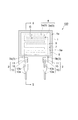
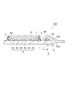
図1は、本発明に係る湿度センサ素子の好適な実施形態を模式的に示す平面図である。図2は、図1のII−II線に沿った概略断面図である。
(Humidity sensor element)
FIG. 1 is a plan view schematically showing a preferred embodiment of a humidity sensor element according to the present invention. FIG. 2 is a schematic sectional view taken along line II-II in FIG.
図1及び図2に示すように、湿度センサ素子100は絶縁基板1を有し、絶縁基板1の一面1a上には、抵抗変化を検出する一対の櫛形電極3が設けられている。一対の櫛形電極3は、それぞれ抵抗変化の検出に寄与する検出部3aと、抵抗変化の検出に寄与しない非検出部3bとで構成されている。一対の櫛形電極3の検出部3a同士は、一定のギャップGを介して互いに噛み合うように対向配置されている。これら一対の検出部3aは、後述する感湿膜9の抵抗変化を検出する検出電極部4として機能する。各櫛形電極3の端部、詳細には非検出部3bの端部には端子2が接続されている。従って、検出部3aと端子2とは非検出部3bを介して電気的に接続されることとなる。
As shown in FIGS. 1 and 2, the
端子2は、絶縁基板1の一面1a上に設けられた電極パッド11と、電極パッド11に対して電気的に接続されたリード線13とを有している。電極パッド11は、半田15を介してリード線13と電気的に接続されている。
The
なお、リード線13は、本体部13aの途中から分岐する挟持部13bを有しており、挟持部13bと本体部13aの先端部13cとによって絶縁基板1の縁部及び電極パッド11が挟まれており、これによりリード線13が電極パッド11に強固に固定されることになる。
The
また、絶縁基板1の一面1a上には、検出電極部4を取り囲む環状仕切り部5が設けられている。詳細には、環状仕切り部5は、検出電極部4が内側に配置され、端子2が外側に配置されるように設けられている。ここで、環状仕切り部5の一部は、各櫛形電極3上において櫛形電極3を検出部3aと非検出部3bとに仕切るように設けられている。また、絶縁基板1の一面1a上であって環状仕切り部5の内側には、環状仕切り部5の内側の面5aに接するように下地膜7が設けられている。この下地膜7上に感湿膜9が設けられている。
Further, on the one
ここで、感湿膜9について詳細に説明する。
Here, the moisture
感湿膜9は、下記一般式:
で表される化合物と、下記一般式:
で表される化合物とを含む混合物の架橋物を含有するものである。
The moisture
And the following general formula:
Containing a cross-linked product of a mixture containing
上記湿度センサ素子100によれば、上記式(II)におけるY11およびY12のいずれか一方がエチレン性不飽和反応性基を末端に有することにより、出力安定性を十分に向上させることができる。従って、湿度センサ素子100は、より長期間の使用にも耐えることができる。
According to the
上記一般式(I)で表される化合物は、4級アンモニウム塩基を主鎖中に含む4級アンモニウム塩ポリマーであり、上記一般式(I)において、Y1 〜Y6 は一価基を表し、Y1 〜Y6 のうち少なくとも一つは、エチレン性不飽和反応性基を末端に有する基である。このような一価基としては、アクリロイルオキシ基、メタクリロイルオキシ基、アクリロイルイミノ基、メタクリロイルイミノ基、ビニル基、アリル基、ジアリルメチル基、アリルオキシ基、ジアクリロイルイミノ基、ジメタクリロイルイミノ基等が挙げられる。 The compound represented by the general formula (I) is a quaternary ammonium salt polymer containing a quaternary ammonium base in the main chain. In the general formula (I), Y 1 to Y 6 represent a monovalent group. , Y 1 to Y 6 are groups having an ethylenically unsaturated reactive group at the terminal. Examples of such monovalent groups include an acryloyloxy group, a methacryloyloxy group, an acrylo leumino group, a methacrylo leumino group, a vinyl group, an allyl group, a diallyl methyl group, an allyloxy group, a diacrylo leumino group, and a dimethacrylo rimino group. It is done.
また、Y1 〜Y6 で表されるエチレン性不飽和反応性基を末端に有する基以外の基としては、アルキル基、アルケニル基、ハロゲン原子等が挙げられる。ハロゲン原子としては塩素、臭素、ヨウ素等が挙げられる。 Examples of the group other than the group having an ethylenically unsaturated reactive group represented by Y 1 to Y 6 at the terminal include an alkyl group, an alkenyl group, and a halogen atom. Examples of the halogen atom include chlorine, bromine and iodine.
Aで表される二価基としては、アルキレン基、アルケニレン基、アリーレン基またはこれらの組合せが好ましい。 As the divalent group represented by A, an alkylene group, an alkenylene group, an arylene group or a combination thereof is preferable.
Bで表される二価基としては、アルキレン基、オキシ基(−O−)およびカルボニル基(−CO−)のうちの1種以上が介在したアルキレン基、アルケニレン基、アリーレン基またはこれらの組合せが好ましい。 Examples of the divalent group represented by B include an alkylene group, an alkenylene group, an arylene group, or a combination thereof, in which one or more of an alkylene group, an oxy group (—O—), and a carbonyl group (—CO—) are interposed. Is preferred.
X1 −、X2 −はハロゲン化物イオンを表し、具体的には塩化物イオン、臭化物イオン、ヨウ化物イオン等であってよいが、塩化物イオン、臭化物イオンが好ましい。これらを複数組み合わせて、所望の特性が得られるようにしてもよい。これらのX1 −、X2 −は通常同一であるが、各々異なっていてもよい。 X 1 − and X 2 − each represent a halide ion, and specifically may be a chloride ion, a bromide ion, an iodide ion, or the like, but a chloride ion or a bromide ion is preferable. A plurality of these may be combined to obtain desired characteristics. These X 1 − and X 2 − are usually the same, but may be different from each other.
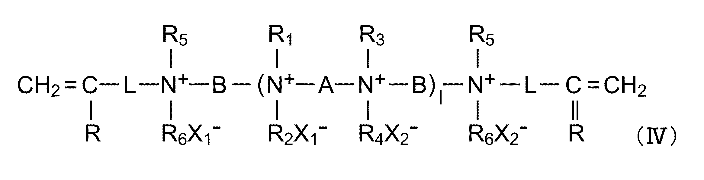
上記4級アンモニウム塩ポリマーとしては、好ましくは下記一般式:
上記式(IV)、(V)において、R1 、R2 、R3 およびR4 は各々アルキル基またはアルケニル基を表す。R1 〜R4 で表されるアルキル基としては、具体的には、メチル基、エチル基、プロピル基、ブチル基等が挙げられる。 In the above formulas (IV) and (V), R 1 , R 2 , R 3 and R 4 each represents an alkyl group or an alkenyl group. Specific examples of the alkyl group represented by R 1 to R 4 include a methyl group, an ethyl group, a propyl group, and a butyl group.
R1 〜R4 で表されるアルケニル基としては、具体的にはビニル基、アリル基、プロペニル基、ブテニル基等が挙げられる。 Specific examples of the alkenyl group represented by R 1 to R 4 include a vinyl group, an allyl group, a propenyl group, and a butenyl group.
上記式(IV)において、R5 およびR6 は、それぞれアルキル基またはアルケニル基を表す。なかでも、アルキル基が好ましく、アルキル基としては、メチル基、エチル基等が好ましいものとして挙げられる。また、R5 、R6 で表されるアルケニル基としては、R1 〜R4 におけるものと同様のものが挙げられる。 In the above formula (IV), R 5 and R 6 each represents an alkyl group or an alkenyl group. Of these, an alkyl group is preferable, and examples of the alkyl group include a methyl group and an ethyl group. As the alkenyl group represented by R 5, R 6, include the same ones in R 1 to R 4.
上記式(IV)、上記式(V)において、Lは二価基を表す。式(II)におけるLの好ましいものとしては、−COO(CH2 )2 −、−CONH(CH2 )3 −、−(CH2 )m −(mは1〜20の整数)などが挙げられる。また、式(III)におけるLの好ましいものとしては、−OCH2 CH2 −、−(CH2 )m −(mは1〜20の整数)、−COO(CH2 )2 −、−COOCH2 CH(OH)CH2 −、−CH2 −C6 H4 −(p−またはm−)などが挙げられる。 In the above formula (IV) and the above formula (V), L represents a divalent group. Preferred examples of L in the formula (II) include —COO (CH 2 ) 2 —, —CONH (CH 2 ) 3 —, — (CH 2 ) m — (m is an integer of 1 to 20), and the like. . As the preferred of L in formula (III), -OCH 2 CH 2 -, - (CH 2) m - (m is an integer of 1 to 20), - COO (CH 2) 2 -, - COOCH 2 CH (OH) CH 2 -, - CH 2 -C 6 H 4 - (p- or m-) and the like.
上記式(IV)、上記式(V)において、Rは水素原子またはアルキル基を表すが、水素原子、メチル基が特に好ましい。 In the formula (IV) and the formula (V), R represents a hydrogen atom or an alkyl group, and a hydrogen atom and a methyl group are particularly preferable.
上記式(IV)、上記式(V)において、X1 −、X2 −はハロゲン化物イオンを表し、具体的には塩化物イオン、臭化物イオン、ヨウ化物イオン等であってよいが、塩化物イオン、臭化物イオンが好ましい。これらを複数組み合わせて、所望の特性が得られるようにしてもよい。これらのX1 −、X2 −は通常同一であるが、各々異なっていてもよい。 In the above formulas (IV) and (V), X 1 − and X 2 − represent halide ions, which may be specifically chloride ions, bromide ions, iodide ions, and the like. Ions and bromide ions are preferred. A plurality of these may be combined to obtain desired characteristics. These X 1 − and X 2 − are usually the same, but may be different from each other.
上記式(I)、上記式(IV)、上記式(V)で示される重合体の数平均分子量Mn は500〜100万、特に1000〜100万、さらには500〜10万程度である。また、ハンドリング性を考慮すると分子量は小さい方が好ましく、1万程度以下がよい。 The number average molecular weight M n of the polymer represented by the above formula (I), the above formula (IV) or the above formula (V) is about 500 to 1,000,000, particularly 1,000 to 1,000,000, and more preferably about 500 to 100,000. Moreover, when handling property is considered, the one where molecular weight is smaller is preferable and about 10,000 or less is good.
上記式(IV)の重合体は、化13に示すようなスキームに従って得られる。
即ちまず、ジアミン化合物とジハロゲン化合物との反応から、4級アンモニウム塩基を有し末端基がハロゲンである中間重合体Iを得る。 That is, first, an intermediate polymer I having a quaternary ammonium base and a terminal group being halogen is obtained from the reaction of a diamine compound and a dihalogen compound.
このときの反応はメタノール、イソプロパノール、メトキシエタノール、2−エトキシエタノール等の非水溶媒中で還流温度あるいは100℃程度の温度にて5〜100時間程度行う。 The reaction at this time is carried out for about 5 to 100 hours at a reflux temperature or a temperature of about 100 ° C. in a non-aqueous solvent such as methanol, isopropanol, methoxyethanol or 2-ethoxyethanol.
次に、エチレン性不飽和反応性基を有する化合物Aを中間重合体Iと反応させ、中間重合体Iの両末端にエチレン性不飽和反応性基を導入して上記一般式(IV)の重合体を得る。 Next, the compound A having an ethylenically unsaturated reactive group is reacted with the intermediate polymer I, an ethylenically unsaturated reactive group is introduced into both ends of the intermediate polymer I, and the above-described general formula (IV) Get coalesced.
一方、式(V)の重合体は、化14に示すようなスキームに従って得られる。
まず、ジアミン化合物とジハロゲン化合物との反応から、4級アンモニウム塩基を有し末端基がアミノ基である中間重合体IIを得る。なお、XはX1 −又はX2 −を表す。 First, an intermediate polymer II having a quaternary ammonium base and having an amino group as a terminal group is obtained from a reaction between a diamine compound and a dihalogen compound. Incidentally, X is X 1 - or X 2 - represents a.
次に、エチレン性不飽和反応性基を有する化合物Bを中間重合体IIと反応させ、中間重合体IIの両末端エチレン性不飽和反応性基を導入して式(V)の重合体を得る。 Next, the compound B having an ethylenically unsaturated reactive group is reacted with the intermediate polymer II, and both end ethylenically unsaturated reactive groups of the intermediate polymer II are introduced to obtain a polymer of the formula (V). .
式(IV)、式(V)で示される重合体は、ジアミン化合物とジハロゲン化合物との反応によって得られるものであり、化10,化11のスキームに従う反応が可能なものであれば、用いられるジアミン化合物およびジハロゲン化合物はいずれであってもよく、特に限定されるものではない。
The polymers represented by the formulas (IV) and (V) are obtained by the reaction of a diamine compound and a dihalogen compound, and can be used as long as they can react according to the schemes of
また上記一般式(II)で表される化合物は、4級アンモニウム塩基を主鎖中に含む4級アンモニウム塩ポリマーであり、上記一般式(II)において、Y11 〜Y16は一価基を表し、Y11 〜Y16は一価基を表し、Y11 およびY16のいずれか一方は、エチレン性不飽和反応性基を末端に有する基である。このような一価基としては、上記一般式(I)におけるY1〜Y6と同様の基が挙げられる。
The compound represented by the general formula (II) is a quaternary ammonium salt polymer containing a quaternary ammonium base in the main chain. In the general formula (II), Y 11 to Y 16 represent a monovalent group. represents,
また、Y11 〜Y16 で表されるエチレン性不飽和反応性基を末端に有する基以外の基は、上記一般式(I)におけるY1〜Y6と同様である。
Also, groups other than the groups with an ethylenically unsaturated reactive group represented by
A11は、上記一般式(I)におけるA11と同様である。B11は、上記一般式(I)におけるB11と同様である。X11 −、X12 −は、上記一般式(I)におけるX1 −、X2 −と同様である。 A 11 is the same as A 11 in the general formula (I). B 11 is the same as B 11 in the general formula (I). X 11 − and X 12 − are the same as X 1 − and X 2 − in the general formula (I).
上記4級アンモニウム塩ポリマーとしては、好ましくは下記一般式:
上記式(VI)、(VII)において、R1 、R2 、R3 およびR4 は、上記一般式(IV)、(V)におけるR1 、R2 、R3 およびR4 と同様である。 The formula (VI), in (VII), R 1, R 2, R 3 and R 4, the general formula (IV), is the same as R 1, R 2, R 3 and R 4 in (V) .
上記式(VI)、上記式(VII)において、Lは上記一般式(IV)、(V)におけるLと同様である。 In the above formulas (VI) and (VII), L is the same as L in the above general formulas (IV) and (V).
上記式(VI)、上記式(VII)において、R7はエチレン性不飽和反応性基以外の一価基を表し、このようなエチレン性不飽和反応性基以外の一価基としては、例えばアルキル基、アルケニル基、ハロゲン原子等が挙げられる。 In the above formulas (VI) and (VII), R 7 represents a monovalent group other than the ethylenically unsaturated reactive group. Examples of the monovalent group other than such an ethylenically unsaturated reactive group include: Examples thereof include an alkyl group, an alkenyl group, and a halogen atom.
上記式(VI)、(VII)において、X11 −、X12 −は、上記一般式(IV)、(V)におけるX1 −、X2 −と同様である。 In the above formulas (VI) and (VII), X 11 − and X 12 − are the same as X 1 − and X 2 − in the general formulas (IV) and (V).
上記一般式(I)で表される化合物と上記一般式(II)で表される化合物とを含む混合物は、さらに下記一般式:
で表される化合物を含むことが好ましい。
A mixture containing the compound represented by the above general formula (I) and the compound represented by the above general formula (II) is further represented by the following general formula:
It is preferable that the compound represented by these is included.
この場合、感湿膜の柔軟性が増すために、温湿度変化による膨潤収縮での感湿膜のクラッキングが減少する。また膜の吸水速度と脱水速度が等しくなる傾向が高まり、ヒステリシスがなくなる。 In this case, since the flexibility of the moisture sensitive film increases, cracking of the moisture sensitive film due to swelling and shrinkage due to temperature and humidity changes decreases. Moreover, the tendency for the water absorption rate and dehydration rate of the membrane to become equal increases, and hysteresis is eliminated.
また上記一般式(III)で表される化合物は、4級アンモニウム塩基を主鎖中に含む4級アンモニウム塩ポリマーであり、上記一般式(III)において、Y21〜Y26 は一価基を表し、Y21 〜Y26 は一価基を表し、Y21 およびY26のいずれも、エチレン性不飽和反応性基を末端に有する基以外の基である。このような一価基としては、上記一般式(I)におけるY1〜Y6と同様の基が挙げられる。 The compound represented by the general formula (III) is a quaternary ammonium salt polymer containing a quaternary ammonium base in the main chain. In the general formula (III), Y 21 to Y 26 each represent a monovalent group. It represents, Y 21 to Y 26 represents a monovalent group, none of Y 21 and Y 26, is a group other than a group having an ethylenically unsaturated reactive group at the terminal. Examples of such a monovalent group include the same groups as Y 1 to Y 6 in the general formula (I).
また、Y21 〜Y26 で表されるエチレン性不飽和反応性基を末端に有する基以外の基は、上記一般式(I)におけるY1〜Y6と同様である。 Also, groups other than the groups with an ethylenically unsaturated reactive group represented by Y 21 to Y 26 at the end is the same as Y 1 to Y 6 in the general formula (I).
A21は、上記一般式(I)におけるAと同様である。B21は、上記一般式(I)におけるBと同様である。X21 −、X22 −は、上記一般式(I)におけるX1 −、X2 −と同様である。 A 21 is the same as A in the general formula (I). B 21 is the same as B in the general formula (I). X 21 − and X 22 − are the same as X 1 − and X 2 − in the general formula (I).
上記4級アンモニウム塩ポリマーとしては、好ましくは下記一般式:
上記式(VIII)、(IX)において、R1 、R2 、R3 およびR4 は、上記一般式(IV)、(V)におけるR1 、R2 、R3 およびR4 と同様である。 The formula (VIII), in (IX), R 1, R 2, R 3 and R 4, the general formula (IV), is the same as R 1, R 2, R 3 and R 4 in (V) .
上記式(VIII)、上記式(IX)において、Lは上記一般式(IV)、(V)におけるLと同様である。 In the above formulas (VIII) and (IX), L is the same as L in the above general formulas (IV) and (V).
上記式(VIII)、上記式(IX)において、R7はエチレン性不飽和反応性基以外の一価基を表し、このようなエチレン性不飽和反応性基以外の一価基としては、例えばアルキル基、アルケニル基、ハロゲン原子等が挙げられる。 In the above formula (VIII) and the above formula (IX), R 7 represents a monovalent group other than the ethylenically unsaturated reactive group. Examples of the monovalent group other than such an ethylenically unsaturated reactive group include: Examples thereof include an alkyl group, an alkenyl group, and a halogen atom.
上記式(VIII)、(IX)において、X21 −、X22 −は、上記一般式(IV)、(V)におけるX1 −、X2 −と同様である。 In the above formulas (VIII) and (IX), X 21 − and X 22 − are the same as X 1 − and X 2 − in the general formulas (IV) and (V).
また感湿膜9に含まれる架橋物において、上記一般式(I)で表される化合物に対する上記一般式(II)で表される化合物の重量比は、8%以下であることが好ましく、5%以下であることがより好ましい。上記重量比が8%を超えると、重量比が8%以下である場合に比べて湿度センサ素子100の耐水性が著しく悪化する傾向がある。
In the crosslinked product contained in the moisture
また感湿膜9の膜厚は、好ましくは1〜10μmであり、より好ましくは3〜8μmである。感湿膜9の膜厚が1μm未満では、感湿膜9の膜厚が1μm以上である場合に比べてガスの影響で出力が変動する傾向がある。一方、感湿膜9の膜厚が10μmを超えると、10μm未満である場合に比べて感湿膜9が剥がれ易くなったり、表面にクラックが発生する傾向が見られる。
The film thickness of the moisture
(湿度センサ素子の製造方法)
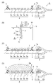
次に、図2及び図3(A)〜図3(D)を参照して、上述した湿度センサ素子100の製造方法の一形態について説明する。図3(A)〜図3(D)は、それぞれ湿度センサ素子100の製造工程を示す概略図である。
(Method for manufacturing humidity sensor element)
Next, with reference to FIG.2 and FIG.3 (A)-FIG.3 (D), one form of the manufacturing method of the
まず、上記一般式(I)で表される4級アンモニウム塩ポリマーと、上記一般式(IV)で表される4級アンモニウム塩ポリマーと、これらを溶解する溶媒とを混合して感湿膜溶液を調製する。 First, a quaternary ammonium salt polymer represented by the above general formula (I), a quaternary ammonium salt polymer represented by the above general formula (IV), and a solvent for dissolving them are mixed to obtain a moisture sensitive film solution. To prepare.
上記溶媒は、上記一般式(I)及び(IV)で表される4級アンモニウム塩ポリマーを溶解できるものであれば特に制限されず、かかる溶媒としては、例えばエチルセロソルブ、メチルセロソルブ等のアルコールケトン類、メタノール、エタノール等のアルコール類などが挙げられる。 The solvent is not particularly limited as long as it can dissolve the quaternary ammonium salt polymer represented by the general formulas (I) and (IV). Examples of the solvent include alcohol ketones such as ethyl cellosolve and methyl cellosolve. And alcohols such as methanol and ethanol.
上記感湿膜溶液は重合開始剤を更に含むことが好ましい。重合開始剤としては、特に制限されないが、例えばイルガキュアシリーズ(千葉スペシャリティケミカルズ製)、KAYACUREシリーズ(日本化薬社製)などが用いられる。 The moisture sensitive film solution preferably further contains a polymerization initiator. Although it does not restrict | limit especially as a polymerization initiator, For example, Irgacure series (made by Chiba Specialty Chemicals), KAYACURE series (made by Nippon Kayaku Co., Ltd.), etc. are used.
(櫛形電極及び端子形成工程)
一方、図3(A)に示すように、絶縁基板1の一面1a上に一対の櫛形電極3、端子2及び環状仕切り部5が形成された絶縁基板1(以下、「構造体A」という)を準備する。
(Comb electrode and terminal formation process)
On the other hand, as shown in FIG. 3A, an insulating substrate 1 (hereinafter referred to as “structure A”) in which a pair of comb-shaped
構造体Aを製造するためにはまず絶縁基板1を用意する。絶縁基板1は、必要に応じて公知の方法により洗浄及び乾燥されてもよい。
In order to manufacture the structure A, first, the insulating
続いて、絶縁基板1の一面1a上に一対の電極パッド11を形成した後に、一対の櫛形電極3を形成する。このとき、電極パッド11と櫛形電極3とが電気的に接続されるように櫛形電極3を形成する。櫛形電極3は、例えばガラスフリットを含有する低抵抗ペーストをスクリーン印刷した後に高温焼結することにより得られる。ここでは、電極パッド11として、例えば銀−白金でコーティングされた銅パッドを用い、リード線13として、リン青銅を用いることとする。なお、櫛形電極3は、抵抗変化の検出に寄与する検出部3aをそれぞれ有している。
Subsequently, after forming a pair of
続いて、電極パッド11にリード線13を取り付ける。その後、図3(A)に示すように、半田15によりリード線13を電極パッド11に固定する。なお、この後、必要に応じて、例えば半田フラックスを除去するためにリード線13の周辺をアルコール洗浄してもよい。このようにして、櫛形電極3の検出部3aに電気的に接続された端子2が形成される。
Subsequently, the
(仕切り部形成工程)
次に、図3(A)に示されるように、絶縁基板1の一面1a上に、検出電極部4が内側に配置され一対の端子2が外側に配置されるように検出電極部4を取り囲む環状仕切り部5を形成する。このとき、環状仕切り部5の一部が検出部3aと非検出部3bとの間を横切るようにする。こうして検出電極部4と端子2とが環状仕切り部5によって仕切られることとなる。環状仕切り部5の形成は、例えばディスペンサ法を用いてフッ素樹脂を環状に塗布した後に乾燥させることで行うことができる。ディスペンサ法を用いると、検出電極部4上にマスキング材等を塗布する必要がないので、可塑剤等の有機物が検出電極部4上に残存することがない。このため、マスキング材等に起因する異物の混入を防止できると共に、かかる異物に起因する感湿膜9の剥離及び湿度センサ素子100の特性劣化を十分に防止できる。こうして構造体Aが得られる。
(Partition formation process)
Next, as shown in FIG. 3A, the
(水処理工程)
次に、図3(B)に示されるように、水槽bに収容された水wに、構造体Aを浸漬させる。このとき、端子2が水wに浸漬しないようにする。これにより絶縁基板1を水wに浸漬させる。また構造体Aを水wに浸漬させている間は、必要に応じて超音波をかける。その後、構造体Aを水wから引き上げて乾燥させる。
(Water treatment process)
Next, as shown in FIG. 3B, the structure A is immersed in the water w accommodated in the water tank b. At this time, the
(下地膜形成工程)
次に、図3(C)に示されるように、絶縁基板1の一面1a上であって環状仕切り部5の内側に下地膜7を形成する。下地膜7は、環状仕切り部5の内側の面5aに接するように形成する。下地膜7は、例えば下地膜形成用溶液を絶縁基板1上に塗布した後に乾燥することで形成することができる。この場合、下地膜7の厚さは環状仕切り部5に近づくにつれて厚くなる傾向にある。下地膜形成用溶液の塗布方法としては、浸漬法等を用いることができる。なお、こうして形成される下地膜7の厚さは、EPMA等を用いて解析することができる。
(Under film forming process)
Next, as shown in FIG. 3C, a
下地膜形成用溶液は、上述のシラン化合物を含む。このようにしてシラン化合物を用いて下地膜7を形成すると、絶縁基板1と下地膜7との接着性が向上する。
The base film forming solution contains the above-described silane compound. When the
(感湿膜形成工程)
次に、図3(D)に示されるように、環状仕切り部5の内側の下地膜7上に、感湿膜9を形成するための感湿膜溶液9aを塗布する。
(Moisture sensitive film formation process)
Next, as shown in FIG. 3D, a moisture
感湿膜溶液9aとしては、上記のようにして得られる感湿膜溶液が用いられる。感湿膜溶液中の4級アンモニウム塩ポリマーとしては、例えば上記一般式(I)、(IV)に示した4級アンモニウム塩ポリマー中のX−、X11 −、X12 −が、臭化物イオン又は塩化物イオン等であるものを用いる。
As the moisture
塗布方法としてはディスペンス法が特に好ましい。その他には、例えば浸漬(ディッピング)法、刷毛塗り法、グラビア印刷法、スクリーン印刷法、スピナー塗布法、インクジェット法等種々の方法が使用でき、工程や製品の用途・種類等により選択すればよい。浸漬法は簡便な方法であるが、ディスペンス法に比べて塗布量の制御が困難となる傾向にある。ディスペンス法では、感湿膜溶液9aの滴下量の制御が可能であるので、塗布量の制御も容易である。
As a coating method, a dispensing method is particularly preferable. In addition, various methods such as a dipping method, a brush coating method, a gravure printing method, a screen printing method, a spinner coating method, and an ink jet method can be used, and may be selected depending on the process and the use / type of the product. . The dipping method is a simple method, but it tends to be difficult to control the coating amount as compared with the dispensing method. In the dispensing method, it is possible to control the dripping amount of the moisture-
続いて、感湿膜溶液9aを乾燥させる。その後、感湿膜溶液9a中の感湿材料を架橋処理する(架橋工程)。架橋処理は、具体的には紫外線照射等によって行うことができる。こうして、図2に示すように、下地膜7上に感湿膜9が形成される。
Subsequently, the moisture
このとき、下地膜7がシラン化合物を用いて形成されている場合には、シラン化合物を用いないで下地膜7を形成する場合に比べて、下地膜7と感湿膜9との接着性が向上する。またシラン化合物を用いて下地膜7を形成する場合には、上記水処理工程が行われると、水処理工程を行わない場合に比べて、絶縁基板1とシラン化合物を含む下地膜7との接着性をより十分に向上させることができる。このため、下地膜7の剥離に伴う感湿膜9の剥離を十分に防止できる。また感湿材料が架橋処理されているため、この場合、結露等により感湿膜9に水分が付着しても、感湿膜9の剥離が十分に防止される湿度センサ素子100を得ることができる。
At this time, when the
上記各工程を経ることによって、湿度センサ素子100が得られる。
The
上記湿度センサ素子100の製造方法によれば、耐水性及び出力安定性が十分に高い湿度センサ素子100が得られる。
According to the manufacturing method of the
なお、上記製造方法によれば、下地膜7が環状仕切り部5の内側の面に接するように形成されるため、環状仕切り部5と下地膜7との間の境界が十分にシールされることになる。このため、感湿膜溶液9aを用いて感湿膜9を形成する場合でも、感湿膜溶液9aが環状仕切り部5と下地膜7との間の境界から環状仕切り部5の外側に漏れ出すことが十分に防止され、感湿膜溶液9aと端子2との接触が十分に防止される。ここで、感湿膜溶液9a中の感湿材料がハロゲン化物イオンを含んでおり、端子2がリン青銅を含んでいるため、仮に、感湿材料が端子2に接触した場合には端子2が腐食してしまう状況にある。しかし、上述したように、上記製造方法では、感湿膜9の形成時において、感湿膜溶液9aと端子2との接触が十分に防止される。このため、ハロゲン化物イオンによる端子2の腐食が十分に防止される。従って、信頼性が高く寿命が長い湿度センサ素子100を製造することができる。
In addition, according to the said manufacturing method, since the
また、上述した湿度センサ素子100の製造方法では、上記感湿膜溶液9aがイオン導電性高分子を含んでいるが、上述したように、感湿膜9の形成時において、感湿膜溶液9aが環状仕切り部5の外側に染み出すことが十分に防止される。従って、感湿膜溶液9aが一対の端子2間に広がることによるショートの発生が十分に防止され、湿度センサ素子の著しい特性劣化が十分に防止される。
Moreover, in the manufacturing method of the
更に、感湿膜溶液9aは、フッ素樹脂で構成される環状仕切り部5に対して撥液性を有する。このため、感湿膜溶液9aは、感湿膜9の形成時において、環状仕切り部5の中央部で環状仕切り部5よりも高く盛り上がることとなり、感湿膜9の厚さを十分に大きくすることができるとともに、感湿膜9の膜厚の面内バラツキを低減できる。
Furthermore, the moisture
本発明は、上記実施形態に限定されるものではない。例えば上記実施形態では、絶縁基板1の一面1a及び検出電極部4の上に下地膜7を形成しているが、下地膜形成工程は本発明の湿度センサ素子の製造方法において必ずしも必要なものではなく、省略することが可能である。
The present invention is not limited to the above embodiment. For example, in the above embodiment, the
また上記実施形態では、絶縁基板1の一面1a上に環状仕切り部5が形成されているが、環状仕切り部5も、本発明の湿度センサ素子の製造方法において必ずしも必要なものではなく、省略することが可能である。
Moreover, in the said embodiment, although the
以下、実施例及び比較例を用いて本発明を更に具体的に説明するが、本発明は以下の実施例に限定されるものではない。 EXAMPLES Hereinafter, although this invention is demonstrated further more concretely using an Example and a comparative example, this invention is not limited to a following example.
<実施例1>
N,N,N’,N’−テトラメチルジアミノ−1,6−ヘキサン6.30g(36.6mmol)と1,12−ジブロモドデカン14.39g(43.9mmol)を、25gのメタノールに溶解し、110℃に加熱したオイルバスの加温により48時間反応させた。反応後溶液を冷却してさらに5gのメタノールを加えた。この溶液を2Lのアセトンに攪拌しながら加え、再沈殿を起こさせて18.47gの白色沈殿を得た。
<Example 1>
N, N, N ′, N′-tetramethyldiamino-1,6-hexane 6.30 g (36.6 mmol) and 1,12-dibromododecane 14.39 g (43.9 mmol) were dissolved in 25 g of methanol. The mixture was reacted for 48 hours by heating an oil bath heated to 110 ° C. After the reaction, the solution was cooled and an additional 5 g of methanol was added. This solution was added to 2 L of acetone with stirring to cause reprecipitation to obtain 18.47 g of a white precipitate.
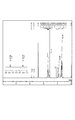
続いて、この白色沈殿5.07gとジメチルアミノプロピルメタクリルアミド2.98gをメタノール20gに溶解し、80℃に加熱したオイルバスの加温により24時間反応させ、アセトン中の逆再沈操作により淡黄色沈殿を5.07g得た。数平均分子量は5200であった。この物質は式(I)の化合物でY1とY6の両方がエチレン性不飽和反応性基に相当する(以下、この化合物を「化合物1」という)。こうして得られた物質についてNMR測定を行った。結果を図4に示す。図4は、上記化合物1のH−NMRチャート図である。なお、C−NMRとあわせた吸収の帰属を表1に示す。
ここで、帰属がはっきりしていて、ピークが重なり合わない部分のH−NMRの積分比から、化合物1のリピートユニット数と、末端に導入したメタクリル酸アミドの数比が決定される。末端ビニルアミド基のビニル基の部分と、化合物1のN−メチル基の部分は、各々ケミカルシフトが5.4ppm付近と3.1ppmと離れているため、両者のピークの積分から計算が可能であり、計算した結果、化合物1は、両末端のメタクリルアミド基に対して、ポリマーのユニットは10個相当であることが分かった。
Here, the number ratio of the repeat unit of
さらに、先の白色沈殿5.33gとジメチルアミノプロピルメタクリルアミド1.02gをメタノール20gに溶解し、70℃に加熱したオイルバスの加温により24時間反応させ、アセトン中の逆再沈操作により淡黄色沈殿を4.83g得た。数平均分子量は5200であった。この物質は式(IV)の化合物でY11かY12のいずれか一方がエチレン不飽和基である化合物(以下、「化合物2」という)と、Y11とY12がいずれもエチレン性不飽和反応性基ではない化合物(以下、「化合物3」という)の混合物(以下、「混合物1」という)である。ここで、化合物1と化合物2の量比を、NMRで確認した。
Further, 5.33 g of the white precipitate and 1.02 g of dimethylaminopropyl methacrylamide were dissolved in 20 g of methanol, reacted for 24 hours by heating in an oil bath heated to 70 ° C., and lightly precipitated by reverse reprecipitation operation in acetone. 4.83 g of a yellow precipitate was obtained. The number average molecular weight was 5200. This substance is a compound of the formula (IV) in which either Y11 or Y12 is an ethylenically unsaturated group (hereinafter referred to as “
その結果、同一のユニットを使って合成した化合物で化合物2と化合物3との混合物1においては、95%がいずれか一方が化合物2であり、残りの5%が化合物3であった。
As a result, in the
そして、上記化合物1と、上記化合物2及び化合物3の混合物1とを9:1の割合で混合して、その5%(質量百分率)エチルセルソルブ溶液を10ml作成し、重合開始剤として0.2%(質量百分率)のKAYACURE ABQ(日本化薬社製)を添加し、こうして得られる溶液を感湿膜形成用モノマー液とした。感湿膜形成用モノマー液は4℃で保管した。
And the said
他方、絶縁基板としてアルミナ製の多孔性セラミック基板を用意し、絶縁基板の一面上に、RuO2とガラスフリットとを含むペーストをスクリーン印刷し、高温焼成して櫛形電極を形成した。このとき、櫛形電極間のギャップは200μm程度とした。こうして、絶縁基板の一面上に櫛形電極が形成された電極付き基板を得た。 On the other hand, a porous ceramic substrate made of alumina was prepared as an insulating substrate, and a paste containing RuO 2 and glass frit was screen-printed on one surface of the insulating substrate and fired at a high temperature to form a comb electrode. At this time, the gap between the comb electrodes was about 200 μm. In this way, a substrate with an electrode in which a comb electrode was formed on one surface of an insulating substrate was obtained.
続いて、この電極付き基板をイソプロピルアルコール100mlに浸漬し、10分間超音波を印加して洗浄した後、放置により乾燥した。 Subsequently, this electrode-attached substrate was immersed in 100 ml of isopropyl alcohol, washed by applying ultrasonic waves for 10 minutes, and then dried by standing.
乾燥後、日本レーザー電子製UVオゾンクリーナーNL−UV252(4.5W出力UV発生管2本使用)で10分間UVオゾン処理を行った。 After drying, UV ozone treatment was carried out for 10 minutes with a UV ozone cleaner NL-UV252 manufactured by Nippon Laser Electronics (using two 4.5 W output UV generator tubes).
処理後直ちにディスペンサを使って、感湿膜形成用モノマー液を2.75μL塗布した。そして、25℃の状態で15分放置し乾燥させ塗膜を作成した。 Immediately after the treatment, 2.75 μL of the monomer solution for forming a moisture sensitive film was applied using a dispenser. And it was left to stand for 15 minutes in the state of 25 degreeC, and it was made to dry and the coating film was created.
次に、この塗膜に窒素雰囲気下で1分間紫外線を照射し、塗膜中の混合物を架橋させて、感湿膜を得た。この時の紫外線照射量は、1000mJ/cm2で、感湿膜の膜厚は5μmであった。こうして湿度センサ素子を得た。 Next, this coating film was irradiated with ultraviolet rays for 1 minute in a nitrogen atmosphere, and the mixture in the coating film was crosslinked to obtain a moisture sensitive film. The amount of ultraviolet irradiation at this time was 1000 mJ / cm 2 , and the thickness of the moisture sensitive film was 5 μm. A humidity sensor element was thus obtained.
こうして得られた湿度センサ素子について、以下のようにして出力特性の安定性の評価を行った。 The stability of the output characteristics of the thus obtained humidity sensor element was evaluated as follows.
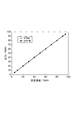
まず、特開平7−229866号公報の第1図に記載の回路に湿度センサ素子を組み込み、回路に組み込んだ湿度センサ素子を分流式湿度発生装置(モデルSRH−1、神栄株式会社製)内に設置し、25℃にて相対湿度を低湿度側から高湿度側へ、続いて高湿度側から低湿度側へ変化させ、その各過程における5%RH、10%RH、20%RH、30%RH、40%RH、50%RH、60%RH、70%RH、80%RH、90%RH、95%RHの各湿度条件下に湿度センサ素子を30分間放置したときの出力電圧を測定した。結果を図5に示す。 First, a humidity sensor element is incorporated in the circuit shown in FIG. 1 of JP-A-7-229866, and the humidity sensor element incorporated in the circuit is installed in a shunt-type humidity generator (model SRH-1, manufactured by Shinei Co., Ltd.). Install and change the relative humidity from low humidity side to high humidity side and then from high humidity side to low humidity side at 25 ° C, 5% RH, 10% RH, 20% RH, 30% in each process The output voltage was measured when the humidity sensor element was left for 30 minutes under each humidity condition of RH, 40% RH, 50% RH, 60% RH, 70% RH, 80% RH, 90% RH, and 95% RH. . The results are shown in FIG.
次に、この湿度センサ素子を60℃90%RHの環境下に置き、240時間放置後の出力特性変化を測定した。結果を図5に示す。 Next, this humidity sensor element was placed in an environment of 60 ° C. and 90% RH, and a change in output characteristics after being left for 240 hours was measured. The results are shown in FIG.
図5に示す結果より、240時間後の出力変動は最大で0.2%RHであった。 From the results shown in FIG. 5, the maximum output fluctuation after 240 hours was 0.2% RH.
また、湿度センサ素子を水に付けて15分間放置し、乾燥後の出力を調べたところ、出力の低下量は0.2%RH以下であった。 Further, when the humidity sensor element was immersed in water and allowed to stand for 15 minutes and the output after drying was examined, the decrease in output was 0.2% RH or less.
<比較例1>
実施例1において上記化合物1の5%(質量百分率)エチルセルソルブ溶液を作成し、重合開始剤として0.2%(質量百分率)のKAYACURE ABQ(日本化薬社製)を添加し、こうして得られる溶液を感湿膜形成用モノマー液としたこと以外は実施例1と同様にして湿度センサ素子を作製した。
<Comparative Example 1>
In Example 1, a 5% (mass percentage) ethyl cellosolve solution of the
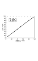
そして、この湿度センサ素子について実施例1と同様にして出力特性の安定性を評価した。結果を図6に示す。図6に示す結果より、240時間後の出力は最大で1.4%RH変化することが分かった。 The stability of the output characteristics of the humidity sensor element was evaluated in the same manner as in Example 1. The results are shown in FIG. From the results shown in FIG. 6, it was found that the output after 240 hours changed by 1.4% RH at the maximum.
また、湿度センサ素子を水に付けて15分間放置し、乾燥後の出力を調べたところ、出力の低下量は0.2%RH以上であった。 Further, when the humidity sensor element was placed in water and allowed to stand for 15 minutes and the output after drying was examined, the amount of decrease in output was 0.2% RH or more.
<比較例2>
実施例1で合成した化合物1と白色沈殿を9:1の割合(質量比)で混合してその5%(質量百分率)のエチルセロソルブ溶液を作製し、重合開始剤として0.2%(質量百分率)のKAYACURE ABQ(日本化薬社製)を添加し、こうして得られる溶液を感湿膜形成用モノマー液としたこと以外は実施例1と同様にして湿度センサ素子を作製した。
<Comparative example 2>
なお、白色沈殿は式(I)で示されるモノマーのうちY1とY2はアルキル基であり、エチレン性不飽和反応基ではない。 In the white precipitation, Y1 and Y2 of the monomers represented by the formula (I) are alkyl groups, not ethylenically unsaturated reactive groups.
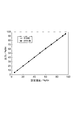
上記のようにして得られた湿度センサ素子について、実施例1と同様にして出力特性の安定性を評価した。結果を図7に示す。図7に示す結果より、240時間後の出力は最大で1.3%RH変化することが分かった。 The stability of the output characteristics of the humidity sensor element obtained as described above was evaluated in the same manner as in Example 1. The results are shown in FIG. From the results shown in FIG. 7, it was found that the output after 240 hours changed by 1.3% RH at the maximum.
また、湿度センサ素子を水に付けて15分間放置し、乾燥後の出力を調べたところ出力の低下量は7%RHであった。 Further, when the humidity sensor element was put on water and allowed to stand for 15 minutes and the output after drying was examined, the amount of decrease in output was 7% RH.
以上の実施例1及び比較例1〜2の結果より、実施例1の湿度センサ素子は、比較例1,2の湿度センサ素子に比べて、出力特性の安定性が十分に高く、且つ耐水性も高いことが分かった。 From the results of Example 1 and Comparative Examples 1 and 2 described above, the humidity sensor element of Example 1 has sufficiently high output characteristics and water resistance compared to the humidity sensor elements of Comparative Examples 1 and 2. It turned out to be expensive.
よって、本発明の湿度センサ素子によれば、耐水性及び出力特性を十分に向上させることができることが確認された。 Therefore, according to the humidity sensor element of this invention, it was confirmed that water resistance and an output characteristic can fully be improved.
1…絶縁基板、3…櫛形電極(電極)、9…感湿膜、100…湿度センサ素子。
DESCRIPTION OF
Claims (3)
前記一対の電極上に設けられる感湿膜とを備えており、
前記感湿膜が下記一般式:
で表される化合物と、下記一般式:
で表される化合物とを含む混合物の架橋物を含有することを特徴とする湿度センサ素子。 A pair of electrodes for detecting a resistance change;
A moisture-sensitive film provided on the pair of electrodes,
The moisture sensitive film has the following general formula:
And the following general formula:
The humidity sensor element characterized by containing the crosslinked material of the mixture containing the compound represented by these.
で表される化合物を更に含むことを特徴とする請求項1に記載の湿度センサ素子。 The mixture has the following general formula:
The humidity sensor element according to claim 1, further comprising a compound represented by the formula:
The cross-linked product contained in the moisture-sensitive film has a weight ratio of the compound represented by the general formula (II) to the compound represented by the general formula (I) of 8% or less. The humidity sensor element according to 1 or 2.
Priority Applications (1)
| Application Number | Priority Date | Filing Date | Title |
|---|---|---|---|
| JP2004105646A JP2005291852A (en) | 2004-03-31 | 2004-03-31 | Humidity sensor element |
Applications Claiming Priority (1)
| Application Number | Priority Date | Filing Date | Title |
|---|---|---|---|
| JP2004105646A JP2005291852A (en) | 2004-03-31 | 2004-03-31 | Humidity sensor element |
Publications (1)
| Publication Number | Publication Date |
|---|---|
| JP2005291852A true JP2005291852A (en) | 2005-10-20 |
Family
ID=35324951
Family Applications (1)
| Application Number | Title | Priority Date | Filing Date |
|---|---|---|---|
| JP2004105646A Withdrawn JP2005291852A (en) | 2004-03-31 | 2004-03-31 | Humidity sensor element |
Country Status (1)
| Country | Link |
|---|---|
| JP (1) | JP2005291852A (en) |
Cited By (2)
| Publication number | Priority date | Publication date | Assignee | Title |
|---|---|---|---|---|
| JP2010186864A (en) * | 2009-02-12 | 2010-08-26 | Shin-Etsu Chemical Co Ltd | Method of manufacturing solar cell, and solar cell |
| WO2015133347A1 (en) * | 2014-03-07 | 2015-09-11 | 富士フイルム株式会社 | Ion-exchange polymer and production method therefor, electrolyte membrane and production method therefor, and composition for producing ion-exchange polymer |
-
2004
- 2004-03-31 JP JP2004105646A patent/JP2005291852A/en not_active Withdrawn
Cited By (4)
| Publication number | Priority date | Publication date | Assignee | Title |
|---|---|---|---|---|
| JP2010186864A (en) * | 2009-02-12 | 2010-08-26 | Shin-Etsu Chemical Co Ltd | Method of manufacturing solar cell, and solar cell |
| WO2015133347A1 (en) * | 2014-03-07 | 2015-09-11 | 富士フイルム株式会社 | Ion-exchange polymer and production method therefor, electrolyte membrane and production method therefor, and composition for producing ion-exchange polymer |
| JP2015180486A (en) * | 2014-03-07 | 2015-10-15 | 富士フイルム株式会社 | Ion-exchangeable polymer and production method thereof, electrolyte film and production method thereof, and composition for producing ion-exchangeable polymer |
| US10279342B2 (en) | 2014-03-07 | 2019-05-07 | Fujifilm Corporation | Ion-exchange polymer and production method therefor, electrolyte membrane and production method therefor, and composition for producing ion-exchange polymer |
Similar Documents
| Publication | Publication Date | Title |
|---|---|---|
| US6568265B2 (en) | Humidity sensor and method for making | |
| WO2002073178A1 (en) | Humidity sensor element and method for manufacture thereof | |
| EP0076131A1 (en) | Humidity sensor and method for preparing a humidity sensor | |
| US5546802A (en) | Humidity sensor and method for making | |
| RU2602489C1 (en) | Gaseous medium capacitive moisture content sensor | |
| JP2005291852A (en) | Humidity sensor element | |
| JP2004531641A (en) | Method for etching a layer deposited on a glass substrate type transparent substrate | |
| JP2808255B2 (en) | Humidity sensor element | |
| JP2005291880A (en) | Humidity sensor element | |
| KR101761891B1 (en) | Method for measuring metal ion permeability of polymer film and apparatus for measuring metal ion permeability of polymer film | |
| JP2003262600A (en) | Humidity sensor element and method of manufacturing the same | |
| JP3967886B2 (en) | Humidity sensor element and manufacturing method thereof | |
| JP2004301766A (en) | Composition for moisture-sensitive material, moisture-sensitive material and humidity sensor element | |
| JP3866991B2 (en) | Humidity sensor element and manufacturing method thereof | |
| JP2006105628A (en) | Humidity sensor element | |
| JP2002340833A (en) | Humidity sensor element and manufacturing method thereof | |
| JP2004354083A (en) | Method of manufacturing humidity sensor element | |
| JP2004271228A (en) | Manufacturing method of humidity sensor element | |
| JP2001221764A (en) | Humidity sensor element and its manufacturing method | |
| JPH10275745A (en) | Conductive polymer terminal and solid electrolytic capacitor | |
| JPS60113140A (en) | Production of moisture sensor element using ionene polymer | |
| JPH0649213A (en) | Ionic electrically conductive material | |
| JPS61237044A (en) | Moisture detection element and manufacture thereof | |
| JPH0630364B2 (en) | Method for encapsulating electrically conductive regions of electronic components and chemical and physical sensors | |
| JP3332423B2 (en) | Electrochemical element |
Legal Events
| Date | Code | Title | Description |
|---|---|---|---|
| A300 | Withdrawal of application because of no request for examination |
Free format text: JAPANESE INTERMEDIATE CODE: A300 Effective date: 20070605 |