JP2005291806A - Radar equipment - Google Patents
Radar equipment Download PDFInfo
- Publication number
- JP2005291806A JP2005291806A JP2004104515A JP2004104515A JP2005291806A JP 2005291806 A JP2005291806 A JP 2005291806A JP 2004104515 A JP2004104515 A JP 2004104515A JP 2004104515 A JP2004104515 A JP 2004104515A JP 2005291806 A JP2005291806 A JP 2005291806A
- Authority
- JP
- Japan
- Prior art keywords
- pulse signal
- radar
- radar apparatus
- transmission
- signal
- Prior art date
- Legal status (The legal status is an assumption and is not a legal conclusion. Google has not performed a legal analysis and makes no representation as to the accuracy of the status listed.)
- Pending
Links
Images

Landscapes
- Radar Systems Or Details Thereof (AREA)
Abstract
【課題】より確実に目標からの反射信号を検出可能なレーダ装置を得ること。
【解決手段】本発明にかかるレーダ装置は、相対距離算出部21が、自レーダ装置の位置情報および所定の伝送路を介して通知される近隣に存在する他のレーダ装置の位置情報に基づいて他のレーダ装置との相対距離を算出し、送信タイミング制御部22が、自レーダ装置が送信するパルス信号の送信時刻を所定の伝送路を介して他のレーダ装置に対して送信し、その後、送信時刻に達した段階でパルス信号を送信し、受信タイミング制御部23が、前記パルス信号の送信時間帯および他のレーダ装置が出力するパルス信号の受信時間帯において受信信号を通過させないように制御し、目標距離算出部24が、自レーダ装置が送信したパルス信号の送信時刻およびそのパルス信号に対する反射信号の受信時刻に基づいて目標との距離を算出する。
【選択図】 図1
A radar apparatus capable of more reliably detecting a reflected signal from a target.
In a radar apparatus according to the present invention, a relative distance calculation unit 21 is based on position information of its own radar apparatus and position information of another radar apparatus existing in the vicinity notified via a predetermined transmission path. The relative distance to the other radar apparatus is calculated, and the transmission timing control unit 22 transmits the transmission time of the pulse signal transmitted by the own radar apparatus to the other radar apparatus via a predetermined transmission path. When the transmission time is reached, a pulse signal is transmitted, and the reception timing control unit 23 controls so that the reception signal does not pass in the transmission time zone of the pulse signal and the reception time zone of the pulse signal output by another radar device. Then, the target distance calculation unit 24 calculates the distance to the target based on the transmission time of the pulse signal transmitted by the radar device and the reception time of the reflected signal with respect to the pulse signal. .
[Selection] Figure 1
Description
本発明は、反射信号から目標の距離を検出するレーダ装置に関するものであり、特に、衛星を利用して近隣に存在するレーダ装置間で位置情報を共有可能なレーダ装置に関するものである。 The present invention relates to a radar apparatus that detects a target distance from a reflected signal, and more particularly to a radar apparatus that can share position information between neighboring radar apparatuses using a satellite.
一般的に、レーダ装置は、空中にパルス変調した電波を送信し、目標(ターゲット)から反射して戻ってきた信号を受信することによって、目標の距離を検出する。このとき、目標からの反射信号は、レーダ装置と目標との相対距離に比例した時間だけ遅延が付加される。 In general, a radar apparatus detects a target distance by transmitting a pulse-modulated radio wave in the air and receiving a signal reflected back from the target (target). At this time, the reflected signal from the target is delayed by a time proportional to the relative distance between the radar apparatus and the target.
ここで、従来のレーダ装置における信号の送受信タイミングについて説明する。従来のレーダ装置は、パルス信号を送信する時間帯については、ブランク動作を行って、受信した信号を通過させず、それ以外の時間帯で受信した信号を通過させる(非特許文献1参照)。すなわち、ブランク動作の時間帯以外で受信した信号を目標からの反射信号として扱い、レーダ装置では、上記相対距離に比例した遅延時間に基づいて目標の距離を検出する。 Here, the signal transmission / reception timing in the conventional radar apparatus will be described. A conventional radar apparatus performs a blank operation for a time zone in which a pulse signal is transmitted, and does not pass a received signal, but passes a signal received in another time zone (see Non-Patent Document 1). That is, a signal received outside the blank operation time zone is treated as a reflected signal from the target, and the radar apparatus detects the target distance based on the delay time proportional to the relative distance.
また、従来のレーダ装置においては、一般的に近隣に存在するレーダ装置が単独で動作するので、通常、近隣に存在するレーダ装置同士は双方の正確な距離情報を把握していない。また、各レーダ装置が個別のタイミングでパルス信号やレンジゲートを動作させている。すなわち、従来のレーダ装置は、目標からの反射信号のほかに、近隣に存在するレーダ装置からのパルス信号等も受信し、その中から目標の距離を検出している(非特許文献1参照)。 In the conventional radar apparatus, since the radar apparatuses existing in the vicinity generally operate independently, the radar apparatuses existing in the vicinity usually do not grasp the accurate distance information of both. Each radar apparatus operates a pulse signal and a range gate at individual timing. That is, the conventional radar apparatus receives not only the reflected signal from the target but also a pulse signal from a nearby radar apparatus, and detects the target distance from the received signal (see Non-Patent Document 1). .
しかしながら、上記従来のレーダ装置では、上述したとおり、目標からの反射信号と近隣に存在するレーダ装置からの送信信号とが受信タイミング(上記ブランク動作の時間帯以外)において共存することとなるため、これらの信号のどれが目標からの反射信号であるのかを区別することが困難である、という問題があった。 However, in the conventional radar device, as described above, the reflected signal from the target and the transmission signal from the radar device existing in the vicinity coexist at the reception timing (other than the time zone of the blank operation), There is a problem that it is difficult to distinguish which of these signals is a reflected signal from the target.
また、従来のレーダ装置では、上述したとおり、近隣に存在するレーダ装置の正確な位置情報を把握することができないので、すなわち、近隣に存在するレーダ装置からのパルス信号が到着するタイミングを推定することができないので、その時間帯にブランク動作を行うことができず、たとえば、近隣に存在するレーダ装置からのパルス信号がジャミングと同じ作用を引き起こして自レーダ装置が誤動作し、本来必要な目標からの反射信号を検出できない場合がある、という問題があった。 Further, as described above, the conventional radar apparatus cannot grasp the accurate position information of the radar apparatus existing in the vicinity, that is, the timing at which the pulse signal from the radar apparatus existing in the vicinity arrives is estimated. Therefore, the blanking operation cannot be performed during that time period. For example, the pulse signal from the radar device in the vicinity causes the same effect as jamming, and the own radar device malfunctions. There is a problem that the reflected signal cannot be detected.
本発明は、上記に鑑みてなされたものであって、近隣に存在する他のレーダ装置の正確な位置および他のレーダ装置の送信タイミングを把握し、より確実に目標からの反射信号を検出可能なレーダ装置を得ることを目的とする。 The present invention has been made in view of the above, and can accurately detect a reflected signal from a target by grasping an accurate position of another radar apparatus in the vicinity and a transmission timing of the other radar apparatus. It is an object to obtain a simple radar device.
上述した課題を解決し、目的を達成するために、本発明にかかるレーダ装置は、送信パルス信号に対する反射信号から目標の距離を検出するレーダ装置において、自レーダ装置の位置情報、および所定の伝送路を介して通知される近隣に存在する他のレーダ装置の位置情報、に基づいて、前記他のレーダ装置との相対距離を算出する相対距離算出手段(後述する実施の形態の相対距離算出部21に相当)と、自レーダ装置が送信するパルス信号の送信開始時刻および送信間隔を、前記所定の伝送路を介して前記他のレーダ装置に対して送信し、その後、前記送信開始時刻および前記送信間隔から得られる送信時刻に達した段階でパルス信号を送信する送信タイミング制御手段(送信タイミング制御部22に相当)と、前記パルス信号の送信時間帯において受信信号を通過させないように制御し、また、前記他のレーダ装置から前記所定の伝送路を介して通知されるパルス信号の送信開始時刻および送信間隔と、前記他のレーダ装置との相対距離と、に基づいて、前記他のレーダ装置が出力するパルス信号の受信時刻を算出し、当該パルス信号の受信時間帯において受信信号を通過させないように制御し、一方で、その他の時間帯において受信信号を通過させる受信タイミング制御手段(受信タイミング制御部23に相当)と、自レーダ装置が送信したパルス信号に対する反射信号を受け取り、自レーダ装置が送信したパルス信号の送信時刻および当該反射信号の受信時刻に基づいて目標との距離を算出する目標距離算出手段(目標距離算出部24に相当)と、を備えることを特徴とする。 In order to solve the above-described problems and achieve the object, a radar apparatus according to the present invention is a radar apparatus that detects a target distance from a reflected signal with respect to a transmission pulse signal. Relative distance calculating means for calculating a relative distance to the other radar device based on the position information of the other radar device existing in the vicinity notified via the road (relative distance calculating unit of the embodiment described later) 21), and the transmission start time and transmission interval of the pulse signal transmitted by the own radar apparatus are transmitted to the other radar apparatus via the predetermined transmission path, and then the transmission start time and the transmission time Transmission timing control means (corresponding to the transmission timing control unit 22) for transmitting a pulse signal when the transmission time obtained from the transmission interval is reached, and at the time of transmission of the pulse signal Control is performed so that the received signal does not pass in the band, and the transmission start time and transmission interval of the pulse signal notified from the other radar device via the predetermined transmission path are relative to the other radar device. Based on the distance, the reception time of the pulse signal output by the other radar device is calculated, and control is performed so that the reception signal is not passed in the reception time zone of the pulse signal, while in other time zones A reception timing control means (corresponding to the reception timing control unit 23) for passing the received signal, and a reflected signal for the pulse signal transmitted by the own radar device are received, and the transmission time of the pulse signal transmitted by the own radar device and the reflected signal And target distance calculation means (corresponding to the target distance calculation unit 24) for calculating the distance from the target based on the reception time. That.
この発明によれば、たとえば、GPS衛星および準天頂衛星を利用して、近隣に存在するレーダ装置の正確な位置を把握し、近隣に存在するレーダ装置が送信するパルス信号の受信時刻(受信タイミング)を特定可能な構成とした。さらに、自レーダ装置が送信したパルス信号に対する反射信号と、近隣に存在するレーダ装置が送信するパルス信号と、が受信タイミングにおいて共存する場合であっても、他のレーダ装置が送信するパルス信号の受信時間帯で受信パルス信号を通過させない構成とした。 According to the present invention, for example, the GPS satellite and the quasi-zenith satellite are used to grasp the accurate position of the radar device existing in the vicinity, and the reception time (reception timing) of the pulse signal transmitted by the radar device existing in the vicinity. ) Can be specified. Furthermore, even when the reflected signal for the pulse signal transmitted by the own radar device and the pulse signal transmitted by the radar device existing in the vicinity coexist at the reception timing, the pulse signal transmitted by another radar device The reception pulse signal is not allowed to pass during the reception time zone.
この発明によれば、上記のように、近隣に存在するレーダ装置の正確な位置を把握し、他のレーダ装置が送信するパルス信号の受信時間帯で受信パルス信号を通過させないこととしたので、より確実に自レーダ装置が送信したパルス信号に対応する反射信号を検出できる、という効果を奏する。 According to the present invention, as described above, the accurate position of the radar device existing in the vicinity is grasped, and the received pulse signal is not allowed to pass in the reception time zone of the pulse signal transmitted by the other radar device. There is an effect that the reflected signal corresponding to the pulse signal transmitted by the own radar apparatus can be detected more reliably.
以下に、本発明にかかるレーダ装置の実施の形態を図面に基づいて詳細に説明する。なお、この実施の形態によりこの発明が限定されるものではない。 Hereinafter, embodiments of a radar apparatus according to the present invention will be described in detail with reference to the drawings. Note that the present invention is not limited to the embodiments.
本実施の形態では、確実に目標からの反射信号を検出可能なレーダ装置の一例として、準天頂衛星システムを介して、近隣に存在する他のレーダ装置との間で位置情報を送受信するレーダ装置について説明する。なお、本発明にかかるレーダ装置は、飛行機,艦船,自動車等、どのような移動体に対しても搭載可能である。 In the present embodiment, as an example of a radar apparatus that can reliably detect a reflected signal from a target, a radar apparatus that transmits / receives position information to / from other radar apparatuses in the vicinity via a quasi-zenith satellite system Will be described. The radar apparatus according to the present invention can be mounted on any moving body such as an airplane, a ship, an automobile, and the like.
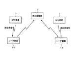
図1は、本発明にかかるレーダ装置を含む衛星通信システムの構成を示す図であり、このシステムは、レーダ装置1−1〜1−N(Nは2以上の整数)と、準天頂衛星2と、GPS(Global Positioning System)衛星3と、から構成されている。ここでは、レーダ装置が、一例として、GPS受信機を備え、GPS衛星3を用いて自レーダ装置の正確な位置を測定する場合について記載している。なお、本実施の形態では、GPS衛星3を用いて自レーダ装置の位置を測定しているが、これに限らず、GPS以外の方法、たとえば、INS(慣性航法装置:Inertial Navigation System)等により自レーダ装置の位置を測定することとしてもよい。
FIG. 1 is a diagram showing a configuration of a satellite communication system including a radar apparatus according to the present invention. This system includes radar apparatuses 1-1 to 1-N (N is an integer of 2 or more) and a
なお、上記準天頂衛星システムは、3機の準天頂衛星2が所定の軌道を通って1日で地球を一周し、3機の準天頂衛星2の少なくとも1機が常に日本の上空(天頂)付近に存在する地域限定型の衛星システムである。また、準天頂衛星2の切り換えを8時間毎に行えば、日本各地において常に60度以上の仰角が確保され、ユーザは、常に、ビル等による通信回線の遮断が少ない良好な移動体通信サービス(自動車電話サービス、携帯電話サービス、GPSとは別の簡易測位システム等)の提供を受けられる。具体的には、日本の主要地域から見た場合は常に天頂から20度以内に準天頂衛星2が存在するため、たとえば、移動体のアンテナを天頂方向に向けておくだけで、移動体の進行方向、飛行体の場合はバンク角が変化しても、常に良好な通信が可能となり、さらに衛星追尾が不要となるため通信装置を簡略化することができる。
In the quasi-zenith satellite system, three quasi-zenith
また、上記レーダ装置(1−1〜1−N)に搭載されるGPS受信機は、4機のGPS衛星3からの電波(測位用信号)を受信することによって各GPS衛星3までの距離を個別に測定し、これらの4つの測定結果から3次元での自レーダ装置の位置を求める。GPS衛星3からの距離は、GPS衛星3が電波を送信して(送信時刻)からGPS受信機に届くまでの時間(受信時刻)に基づいて測定する。なお、GPS衛星3には高精度な原子時計が搭載されているため、GPS衛星3からの測位用信号を受信することにより、各GPS衛星3と同程度の精度の時刻情報を共有することができる。なお、準天頂衛星2からも、GPS衛星3と同様の測位用信号が送信されているため、GPS衛星4機の内の1機を準天頂衛星2としても良い。
In addition, the GPS receivers mounted on the radar devices (1-1 to 1-N) receive the radio waves (positioning signals) from the four
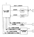
図2は、本発明にかかるレーダ装置の構成を示す図であり、このレーダ装置は、受信ゲート(送受切替管)を制御する送受信タイミング制御機能と、近隣に存在する他のレーダ装置との相対距離および目標(ターゲット)までの距離等を算出する信号処理機能と、を有するタイミング制御/信号処理部11と、測距用の電波を送信する送信機12と、目標からの反射信号を受信する受信機13と、GPS衛星3からの測位用信号に基づいて位置情報を生成するGPS受信機14と、準天頂衛星2との間で必要な情報を送受信する準天頂衛星用送受信機15と、タイミング制御/信号処理部11からの制御で送信/受信動作の切り替えを行う受信ゲート16と、を備えている。なお、上記受信ゲート16は、たとえば、送信/受信をそれぞれ切り離して動作させることを目的とした、導波管の一部に挿入して使用する放電管の一種であるTR管およびATR管である。一般に、レーダ装置は、導波管のT分岐を通して送信機と受信機が接続されているが、上記受信ゲート16により、たとえば、送信時の大きなパルス電力による受信機の損傷を防止することができる。
FIG. 2 is a diagram showing a configuration of a radar apparatus according to the present invention. This radar apparatus has a relative relationship between a transmission / reception timing control function for controlling a reception gate (transmission / reception switching pipe) and other radar apparatuses in the vicinity. A timing control /
また、図3は、上記タイミング制御/信号処理部11の詳細構成を示す図であり、このタイミング制御/信号処理部11は、近隣に存在する他のレーダ装置との相対距離を算出する相対距離算出部21と、パルス信号の送信を制御する送信タイミング制御部22と、受信ゲートの送信/受信動作の切り替えを制御する受信タイミング制御部23と、目標との距離を算出する目標距離算出部24と、を備えている。
FIG. 3 is a diagram illustrating a detailed configuration of the timing control /
ここで、上記のように構成される本発明にかかるレーダ装置の動作を、図面にしたがって説明する。なお、ここでは、一例として、GPS受信機14が、上記で説明したように、近隣に存在するレーダ装置間で共通の時刻情報を生成し、各レーダ装置間で同期が確立されていることとする。なお、上記共通の時刻情報については、これに限らず、通信総合研究所が福島と九州から60KHzおよび40KHzで送信している標準電波でも得ることができる。また、本実施の形態では、図1に示すように、N個のレーダ装置が、準天頂衛星2を介した通信により、他のレーダ装置の位置情報を受信する場合を想定しているが、ここでは、説明の便宜上、レーダ装置1−1の動作について説明する。他のレーダ装置についてはレーダ装置1−1と同様の動作を行う。
Here, the operation of the radar apparatus according to the present invention configured as described above will be described with reference to the drawings. Here, as an example, as described above, the
まず、GPS受信機14では、自受信機の時刻情報と、GPS衛星3から送られてくる測位用信号(送信時刻を含む)と、に基づいて、自レーダ装置1−1の位置情報を生成する。そして、その位置情報を相対距離算出部21に通知する。同時に、生成した自レーダ装置1−1の位置情報を、準天頂衛星用送受信機15,準天頂衛星2経由で、近隣に存在する他のすべてのレーダ装置に対して送信する。なお、本実施の形態においては、たとえば、DGPS(Differential GPS)の補正信号を利用した高精度測位を想定することとしてもよい(図示せず)。高精度測位を想定する場合は、たとえば、GPS受信機14のアンテナで準天頂衛星2からの航法メッセージを受信し、航法メッセージに付加された補正情報に基づいて、上記で求めた自レーダ装置1−1の位置の誤差を補正し、高精度な自レーダ装置1−1の位置を算出することになる。なお、準天頂衛星2から送られてくる航法メッセージは、GPS受信機14のアンテナ(指向性が鋭くない小型のアンテナ)にて受信可能であり、GPS受信機14では、航法メッセージのIDを確認しなければ、GPS衛星3からの信号か、準天頂衛星2からの信号か、を区別することができない。
First, the
一方で、準天頂衛星用送受信機15では、準天頂衛星2経由で、近隣に存在する他のすべてのレーダ装置からの位置情報を受信し、それらの位置情報を相対距離算出部21に通知する。
On the other hand, the
相対距離算出部21では、自レーダ装置1−1の位置情報および上記で受信した近隣に存在する各レーダ装置の位置情報に基づいて、各レーダ装置との相対距離を個別に算出する。そして、求めた他のすべてのレーダ装置との相対距離を受信タイミング制御部23および目標距離算出部24に通知する。なお、相対位置とは、自レーダ装置1−1の位置を(X1,Y1,Z1)とし、近隣に存在する他のレーダ装置の位置を、たとえば、(Xn,Yn,Zn)とした場合(nは2〜Nのいずれか1つで、2〜Nはそれぞれレーダ装置1−2,…1−Nに対応する)、(X1−Xn,Y1−Yn,Z1−Zn)で表すことができる。つまり、自レーダ装置1−1と、各レーダ装置との相対距離lnは、((X1−Xn)2+(Y1−Yn)2+(Z1−Zn)2)1/2で示せる。
The relative
送信タイミング制御部22では、上記GPS受信機14から得られる時刻情報に基づいてパルス信号の送信開始時刻および送信間隔を任意に設定し、設定した送信開始時刻および送信間隔を送信タイミング情報として、準天頂衛星用送受信機15,準天頂衛星2経由で、近隣に存在するすべてのレーダ装置に対して送信する。同時に、上記送信タイミング情報を受信タイミング制御部23および目標距離算出部24に通知する。これにより、すべてのレーダ装置間でレーダ装置1−1の送信タイミング情報を共有することができる。その後、送信タイミング制御部22では、上記時刻情報が送信開始時刻に達した場合、さらには、送信間隔毎に、所定のパルス信号を送信する。
The transmission
受信タイミング制御部23では、上記GPS受信機14から得られる時刻情報および送信タイミング制御部22から通知される送信タイミング情報に基づいて、自レーダ装置1−1のパルス信号の送信開始時刻および送信間隔毎に、受信ゲート16を「送信(OFF)」に設定するための受信ゲート制御信号を生成し、それらの間の受信信号を通過させないように制御する(ブランク動作)。
In the reception
また、受信タイミング制御部23では、他のすべてのレーダ装置から準天頂衛星2,準天頂衛星用送受信機15経由で通知される送信タイミング情報(送信開始時刻,送信間隔)および相対処理算出部21から通知される他のすべてのレーダ装置との相対距離に基づいて、他のすべてのレーダ装置が出力するパルス信号の受信時刻を計算し、当該受信時刻で受信ゲートを「OFF」に設定するための受信ゲート制御信号を生成し、その間の受信信号を通過させないように制御する(ブランク動作)。たとえば、レーダ装置1−nがパルス信号を送信し、そのパルス信号の受信時刻をtRとし、レーダ装置1−nの送信時刻をtTとし、レーダ装置1−nとの相対距離をlとし、光速をcとした場合、上記受信時刻は、「tR=tT+(l÷c)」を演算することにより求められる。なお、上記送信時刻tTは、送信開始時刻tT1、および送信間隔により求められる時刻tT2,tT3,tT4,…のことをいう。ただし、上記ブランク動作の時間帯以外については、受信ゲートを「受信(ON:受信信号通過)」に設定するための受信ゲート制御信号を生成する。
The reception
目標距離算出部24では、受信機13にて受信した自レーダ装置1−1が送信したパルス信号に対する反射信号を受け取り、送信タイミング制御部22から通知される送信タイミング情報(送信開始時刻,送信間隔)および反射信号の受信時刻に基づいて、目標との距離を算出する。たとえば、目標との距離をlTとし、パルス信号を送信してから反射信号を受信するまでの時間をtTRとし、光速をcとした場合、上記目標との距離は、「lT=tTR×c÷2」を演算することにより求められる。
The target
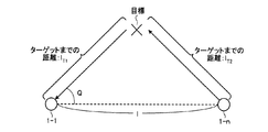
さらに、本実施の形態では、目標距離算出部24が、たとえば、自レーダ装置1−1以外の他のレーダ装置1−n(1−nは1−2〜1−Nのうちのいずれか一つ)が送信したパルス信号に対する反射信号を受け取り、さらに、レーダ装置1−nから準天頂衛星2,準天頂衛星用送受信機15経由で通知される送信タイミング情報(送信開始時刻,送信間隔),相対距離算出部21から得られるレーダ装置1−nとの相対距離,および当該反射信号の受信時刻に基づいて、目標との距離を算出することも可能である。図4は、レーダ装置1−nが送信したパルス信号に対する反射信号をレーダ装置1−1が受信した場合の、レーダ装置1−1による目標までの距離の計算方法を示す図である。たとえば、レーダ装置1−1から目標までの距離をlT1とし、レーダ装置1−nから目標までの距離をlT2とし、レーダ装置1−nがパルス信号を送信してから(送信時刻:tT)レーダ装置1−1が反射信号を受信する(受信時刻:tR)までの時間をtTR(=tT−tR)とし、光速をcとした場合、目標を経由したレーダ装置間の距離lT1+lT2は、
lT1+lT2=tTR×c …(1)
と表すことができる。また、レーダ装置1−1とレーダ装置1−nとを結ぶ直線を基準とした反射電波方向をθとし、上記相対距離算出部21から得られるレーダ装置1−nとの相対距離をlとした場合、
lT1 2+l2−2lT1×l×cosθ=lT2 2 …(2)
が成立する。したがって、目標距離算出部24では、(1)式,(2)式に基づいてレーダ装置1−1から目標までの距離をlT1を算出する。これにより、各レーダ装置が送信するパルス信号を低減できるので、送信パルス信号と反射信号が干渉を起こす確率を低減できる。さらに、秘匿性を向上させることができる。
Furthermore, in the present embodiment, the target
l T1 + l T2 = t TR × c (1)
It can be expressed as. The reflected radio wave direction with reference to the straight line connecting the radar apparatus 1-1 and the radar apparatus 1-n is defined as θ, and the relative distance from the radar apparatus 1-n obtained from the relative
l T1 2 + l 2 -2 l T1 × l × cos θ = l T2 2 (2)
Is established. Therefore, the target
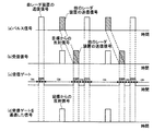
図5は、たとえば、上記のように動作するレーダ装置1−1の特徴的な処理の一例を示す図であり、パルス信号を送信する例を示すが、何らかの変調を掛けても同じである。(a)の処理では、レーダ装置1−1が定期的に特定のパルス幅のパルス信号を送信している様子の一例、および他のレーダ装置1−nが定期的に特定のパルス幅でパルス信号を送信している様子の一例、を表している。なお、ここでは、説明の便宜上、パルス信号を送信している他のレーダ装置が1つの場合を記載しているが、これに限らず、通常は、複数のレーダ装置がパルス信号を送信している。(b)は、レーダ装置1−1が送信したパルス信号に対する目標からの反射信号の受信タイミング、および他のレーダ装置が送信するパルス信号の受信タイミングを表している。他のレーダ装置の送信信号は、上記受信タイミング制御部23にて計算した、他のレーダ装置が送信したパルス信号の受信時刻に到着する。上記(c)では、レーダ装置1−1が送信するパルス信号の送信時刻で受信ゲートをOFF(受信信号を通過させない設定)に設定する処理と、他のレーダ装置が出力するパルス信号の受信時刻で受信ゲートをOFF(受信信号を通過させない設定)に設定する処理、を表している。ここでは、受信パルス信号のパルス幅に応じた受信ゲート制御信号を生成している。(d)では、受信ゲートを通過した信号を表している。すなわち、ここでは、レーダ装置1−1が送信したパルス信号に対する目標からの反射信号のみが受信ゲートを通過している様子、を表している。
FIG. 5 is a diagram illustrating an example of characteristic processing of the radar apparatus 1-1 that operates as described above. For example, a pulse signal is transmitted, but the same applies even if some modulation is applied. In the process (a), an example in which the radar device 1-1 periodically transmits a pulse signal having a specific pulse width, and the other radar device 1-n periodically pulses with a specific pulse width. An example of a state of transmitting a signal is shown. Here, for convenience of explanation, the case where there is one other radar device transmitting a pulse signal is described, but this is not a limitation, and normally, a plurality of radar devices transmit pulse signals. Yes. (B) represents the reception timing of the reflected signal from the target with respect to the pulse signal transmitted by the radar apparatus 1-1 and the reception timing of the pulse signal transmitted by another radar apparatus. The transmission signal of the other radar apparatus arrives at the reception time of the pulse signal transmitted by the other radar apparatus, calculated by the reception
上記の処理によって、レーダ装置1−1では、(b)に示すように、受信信号として、自レーダ装置1−1が送信したパルス信号に対する反射信号と、他のレーダ装置1−nから送られてくるパルス信号と、が共存しているが、(c)に示すように、他のレーダ装置1−nが送信するパルス信号の受信時刻で受信ゲートを「OFF」にしているので、結果として、(d)に示すように、他のレーダ装置1−nが送信するパルス信号を通過させずに、自レーダ装置1−1が送信したパルス信号に対する反射信号のみを通過させることが可能となる。 Through the above processing, as shown in (b), the radar apparatus 1-1 receives the reflection signal for the pulse signal transmitted from the radar apparatus 1-1 and the other radar apparatus 1 -n as received signals. As shown in (c), the reception gate is turned “OFF” at the reception time of the pulse signal transmitted by the other radar apparatus 1-n, as a result. As shown in (d), it is possible to pass only the reflected signal for the pulse signal transmitted by the own radar apparatus 1-1 without passing the pulse signal transmitted by the other radar apparatus 1-n. .
このように、本実施の形態においては、GPS衛星および準天頂衛星を利用して、近隣に存在するレーダ装置の正確な位置を把握し、近隣に存在するレーダ装置が送信するパルス信号の受信時刻(受信タイミング)を特定可能な構成とした。さらに、自レーダ装置が送信したパルス信号に対する反射信号と、近隣に存在するレーダ装置が送信するパルス信号と、が受信タイミングにおいて共存する場合であっても、他のレーダ装置が送信するパルス信号の受信時刻で受信ゲートをOFFに設定し、他のレーダ装置が送信するパルス信号を通過させない構成とした。これにより、確実に、自レーダ装置が送信したパルス信号に対応する反射信号を検出できる。 As described above, in the present embodiment, the GPS satellite and the quasi-zenith satellite are used to grasp the accurate position of the radar device existing in the vicinity, and the reception time of the pulse signal transmitted by the radar device existing in the vicinity (Reception timing) can be specified. Furthermore, even when the reflected signal for the pulse signal transmitted by the own radar device and the pulse signal transmitted by the radar device existing in the vicinity coexist at the reception timing, the pulse signal transmitted by another radar device The reception gate is set to OFF at the reception time, and a pulse signal transmitted by another radar apparatus is not allowed to pass. Thereby, the reflected signal corresponding to the pulse signal transmitted by the own radar apparatus can be reliably detected.
なお、本実施の形態においては、特に準天頂衛星を利用した場合について説明したが、これに限らず、たとえば、アンテナを天頂方向に向けておくだけで常に良好な通信が可能となるような位置に存在する衛星であれば、準天頂衛星以外であっても同様の効果を得ることができる。 In the present embodiment, the case where the quasi-zenith satellite is used has been described. However, the present invention is not limited to this. For example, a position where good communication is always possible by simply pointing the antenna in the zenith direction. The same effect can be obtained with satellites other than the quasi-zenith satellite.
また、本実施の形態においては、送信タイミング制御部22によるパルス信号の送信時刻を特定していない(任意に設定可能)が、一例として、受信ゲートが「OFF」であることを利用して、他のレーダ装置が出力するパルス信号の受信時刻にあわせてパルス信号を送信することとしてもよい。
In the present embodiment, the transmission timing of the pulse signal by the transmission
以上のように、本発明にかかるレーダ装置は、一例として、自動車、航空機等の飛翔体、艦船等に搭載されるレーダ装置として有用であり、特に、他のレーダ装置の位置情報を利用してターゲットを検出するレーダ装置として適している。 As described above, the radar apparatus according to the present invention is useful, for example, as a radar apparatus mounted on a flying object such as an automobile or an aircraft, a ship, and the like, and particularly using position information of other radar apparatuses. It is suitable as a radar device for detecting a target.
1−1〜1−N レーダ装置
2 準天頂衛星
3 GPS衛星
11 タイミング制御/信号処理部
12 送信機
13 受信機
14 GPS受信機
15 準天頂衛星用送受信機
16 受信ゲート
21 相対距離算出部
22 送信タイミング制御部
23 受信タイミング制御部
24 目標距離算出部
1-1 to 1-
Claims (4)
自レーダ装置の位置情報、および所定の伝送路を介して通知される近隣に存在する他のレーダ装置の位置情報、に基づいて、前記他のレーダ装置との相対距離を算出する相対距離算出手段と、
自レーダ装置が送信するパルス信号の送信開始時刻および送信間隔を、前記所定の伝送路を介して前記他のレーダ装置に対して送信し、その後、前記送信開始時刻および前記送信間隔から得られる送信時刻に達した段階でパルス信号を送信する送信タイミング制御手段と、
前記パルス信号の送信時間帯において受信信号を通過させないように制御し、また、前記他のレーダ装置から前記所定の伝送路を介して通知されるパルス信号の送信開始時刻および送信間隔と、前記他のレーダ装置との相対距離と、に基づいて、前記他のレーダ装置が出力するパルス信号の受信時刻を算出し、当該パルス信号の受信時間帯において受信信号を通過させないように制御し、一方で、その他の時間帯において受信信号を通過させる受信タイミング制御手段と、
自レーダ装置が送信したパルス信号に対する反射信号を受け取り、自レーダ装置が送信したパルス信号の送信時刻および当該反射信号の受信時刻に基づいて目標との距離を算出する目標距離算出手段と、
を備えることを特徴とするレーダ装置。 In a radar apparatus that detects a target distance from a reflected signal with respect to a transmission pulse signal,
Relative distance calculating means for calculating a relative distance to the other radar device based on the position information of the own radar device and the position information of another radar device existing in the vicinity notified via a predetermined transmission path When,
The transmission start time and transmission interval of the pulse signal transmitted by the own radar device are transmitted to the other radar device via the predetermined transmission path, and then the transmission obtained from the transmission start time and the transmission interval. Transmission timing control means for transmitting a pulse signal when the time is reached;
Control is performed so that the received signal does not pass in the transmission time zone of the pulse signal, and the transmission start time and transmission interval of the pulse signal notified from the other radar device via the predetermined transmission path, and the other On the basis of the relative distance to the other radar device, the reception time of the pulse signal output by the other radar device is calculated, and control is performed so as not to pass the reception signal in the reception time zone of the pulse signal, Receiving timing control means for passing the received signal in other time zones;
A target distance calculation means for receiving a reflection signal for the pulse signal transmitted by the own radar apparatus and calculating a distance from the target based on a transmission time of the pulse signal transmitted by the own radar apparatus and a reception time of the reflection signal;
A radar apparatus comprising:
Priority Applications (1)
| Application Number | Priority Date | Filing Date | Title |
|---|---|---|---|
| JP2004104515A JP2005291806A (en) | 2004-03-31 | 2004-03-31 | Radar equipment |
Applications Claiming Priority (1)
| Application Number | Priority Date | Filing Date | Title |
|---|---|---|---|
| JP2004104515A JP2005291806A (en) | 2004-03-31 | 2004-03-31 | Radar equipment |
Publications (1)
| Publication Number | Publication Date |
|---|---|
| JP2005291806A true JP2005291806A (en) | 2005-10-20 |
Family
ID=35324912
Family Applications (1)
| Application Number | Title | Priority Date | Filing Date |
|---|---|---|---|
| JP2004104515A Pending JP2005291806A (en) | 2004-03-31 | 2004-03-31 | Radar equipment |
Country Status (1)
| Country | Link |
|---|---|
| JP (1) | JP2005291806A (en) |
Cited By (6)
| Publication number | Priority date | Publication date | Assignee | Title |
|---|---|---|---|---|
| JP2008241429A (en) * | 2007-03-27 | 2008-10-09 | Mitsubishi Electric Corp | Moving object information sharing system |
| WO2012066737A1 (en) * | 2010-11-16 | 2012-05-24 | パナソニック株式会社 | Radar device |
| JP2012221206A (en) * | 2011-04-08 | 2012-11-12 | Nec Corp | Data collection system through satellite |
| US10769239B2 (en) | 2014-11-26 | 2020-09-08 | Maritime Radar Systems Limited | System for monitoring a maritime environment |
| JP2022006248A (en) * | 2020-06-24 | 2022-01-13 | 株式会社エヌエステイー | Distance measuring device and distance measuring method using the same |
| KR102904454B1 (en) * | 2025-03-10 | 2025-12-26 | 국방과학연구소 | Method of correcting alignment status of radar and electronic apparatus therefor |
-
2004
- 2004-03-31 JP JP2004104515A patent/JP2005291806A/en active Pending
Cited By (8)
| Publication number | Priority date | Publication date | Assignee | Title |
|---|---|---|---|---|
| JP2008241429A (en) * | 2007-03-27 | 2008-10-09 | Mitsubishi Electric Corp | Moving object information sharing system |
| WO2012066737A1 (en) * | 2010-11-16 | 2012-05-24 | パナソニック株式会社 | Radar device |
| JP2012107947A (en) * | 2010-11-16 | 2012-06-07 | Panasonic Corp | Radar device |
| US9664777B2 (en) | 2010-11-16 | 2017-05-30 | Panasonic Intellectual Property Management Co., Ltd. | Radar device |
| JP2012221206A (en) * | 2011-04-08 | 2012-11-12 | Nec Corp | Data collection system through satellite |
| US10769239B2 (en) | 2014-11-26 | 2020-09-08 | Maritime Radar Systems Limited | System for monitoring a maritime environment |
| JP2022006248A (en) * | 2020-06-24 | 2022-01-13 | 株式会社エヌエステイー | Distance measuring device and distance measuring method using the same |
| KR102904454B1 (en) * | 2025-03-10 | 2025-12-26 | 국방과학연구소 | Method of correcting alignment status of radar and electronic apparatus therefor |
Similar Documents
| Publication | Publication Date | Title |
|---|---|---|
| US11921184B2 (en) | Methods and apparatus for characterising the environment of a user platform | |
| CN1689191B (en) | A system and method for the mitigation of multipath and the improvement of signal-to-noise ratios in time division multiple access (TDMA) location networks | |
| EP2523019B1 (en) | Global positioning system signal reception with increased resistance to interference | |
| US20100090882A1 (en) | Bi-static radar processing for ads-b sensors | |
| RU2365939C1 (en) | Method of underwater navigation | |
| JPH083522B2 (en) | Navigation method using satellite | |
| AU774161B2 (en) | Improvements in or relating to object location | |
| KR20030041128A (en) | Digital receiving system for dense environment of aircraft | |
| JP5669168B2 (en) | Distance measuring system and distance measuring method | |
| CN101156077A (en) | Positioning system with sparse antenna array | |
| EP1910860B1 (en) | A positioning system and method | |
| JP3613120B2 (en) | Bistatic radar device | |
| US11719782B2 (en) | One-way time-of-flight localization using sonic and electromagnetic signals for mobile ad hoc networks | |
| JP2005291806A (en) | Radar equipment | |
| KR20100064287A (en) | Apparatus and method for avoiding collision | |
| JP3753121B2 (en) | Radar apparatus and radar system | |
| JP2010256133A (en) | Interference prevention radar equipment | |
| CA2741844C (en) | System for positioning a geostationary satellite | |
| KR20190140328A (en) | Electronic scanner to detect moving target | |
| CN119213329A (en) | Method and apparatus for improving co-channel operation of independent radio systems | |
| RU2854085C1 (en) | Method for direction finding of two radio beacons | |
| EP1924029A1 (en) | Method for controlling beam-forming at a base station, and a base station | |
| JP2007147534A (en) | Radar equipment | |
| JP2647054B2 (en) | Precise measurement approach radar system | |
| JP6012235B2 (en) | Interference control device |