JP2005291802A - Magnetic exploration method - Google Patents
Magnetic exploration method Download PDFInfo
- Publication number
- JP2005291802A JP2005291802A JP2004104440A JP2004104440A JP2005291802A JP 2005291802 A JP2005291802 A JP 2005291802A JP 2004104440 A JP2004104440 A JP 2004104440A JP 2004104440 A JP2004104440 A JP 2004104440A JP 2005291802 A JP2005291802 A JP 2005291802A
- Authority
- JP
- Japan
- Prior art keywords
- magnetic field
- magnetic
- axis
- exploration
- axis direction
- Prior art date
- Legal status (The legal status is an assumption and is not a legal conclusion. Google has not performed a legal analysis and makes no representation as to the accuracy of the status listed.)
- Pending
Links
- 238000000034 method Methods 0.000 title claims abstract description 28
- 229910000831 Steel Inorganic materials 0.000 claims abstract description 11
- 239000010959 steel Substances 0.000 claims abstract description 11
- 238000005259 measurement Methods 0.000 claims description 24
- 239000000463 material Substances 0.000 claims description 4
- 238000001514 detection method Methods 0.000 abstract description 6
- XEEYBQQBJWHFJM-UHFFFAOYSA-N Iron Chemical compound [Fe] XEEYBQQBJWHFJM-UHFFFAOYSA-N 0.000 abstract description 4
- 229910052742 iron Inorganic materials 0.000 abstract description 2
- 230000003014 reinforcing effect Effects 0.000 abstract description 2
- 230000005389 magnetism Effects 0.000 description 11
- 238000004364 calculation method Methods 0.000 description 7
- 238000010586 diagram Methods 0.000 description 5
- 230000000694 effects Effects 0.000 description 4
- 239000011150 reinforced concrete Substances 0.000 description 4
- 238000013215 result calculation Methods 0.000 description 4
- 241000238366 Cephalopoda Species 0.000 description 1
- BZHJMEDXRYGGRV-UHFFFAOYSA-N Vinyl chloride Chemical compound ClC=C BZHJMEDXRYGGRV-UHFFFAOYSA-N 0.000 description 1
- 239000003990 capacitor Substances 0.000 description 1
- 239000004567 concrete Substances 0.000 description 1
- 239000000470 constituent Substances 0.000 description 1
- 238000010276 construction Methods 0.000 description 1
- 238000000926 separation method Methods 0.000 description 1
- 229910001220 stainless steel Inorganic materials 0.000 description 1
- 239000010935 stainless steel Substances 0.000 description 1
Images
Landscapes
- Geophysics And Detection Of Objects (AREA)
Abstract
【課題】 本発明は、場所打ち杭等のように鉄筋量が少ない杭や、フーチングによって探査孔を杭から離れたところに配置しなければならない場合にも、高い検知精度で杭長を特定することができる磁気探査方法を提供することを課題とする。
【解決手段】 非磁性ガイド管3にコイル等からなる磁場発生装置4を挿入し、磁場発生装置4を探査軸方向に移動させながら、電源装置5から磁場発生装置4に電源を供給して磁場を発生させ、基礎杭1を磁化させる。基礎杭1に使用されている鉄等の鋼材は、磁場発生装置4によって発生させた磁場によって着磁されることはないが、磁場発生装置4によって発生させた磁場によって残留磁気の磁極の向きが揃うため、基礎杭1の周辺の磁場が強くなる。
【選択図】 図1
PROBLEM TO BE SOLVED: To specify a pile length with high detection accuracy even when a pile having a small amount of reinforcing bars such as cast-in-place piles or when an exploration hole needs to be arranged away from a pile by footing. It is an object of the present invention to provide a magnetic exploration method that can be used.
A magnetic field generator 4 comprising a coil or the like is inserted into a non-magnetic guide tube 3 and the magnetic field generator 4 is moved in the direction of the search axis while power is supplied from the power supply device 5 to the magnetic field generator 4. And the foundation pile 1 is magnetized. Steel such as iron used for the foundation pile 1 is not magnetized by the magnetic field generated by the magnetic field generator 4, but the direction of the remanent magnetic pole is changed by the magnetic field generated by the magnetic field generator 4. Since they are aligned, the magnetic field around the foundation pile 1 becomes stronger.
[Selection] Figure 1
Description
本発明は、磁気探査方法に関し、特に地中に埋設されている基礎杭の先端位置を検出する磁気探査方法に関する。 The present invention relates to a magnetic exploration method, and more particularly to a magnetic exploration method for detecting a tip position of a foundation pile buried in the ground.
施行年度の古い構造物の耐震性判定のためや、老朽化した構造物の更新のためには、基礎杭の杭長を確認しておく必要があるが、図面等が存在しない場合には、基礎杭の杭長を調査しなければならない。 It is necessary to confirm the pile length of the foundation pile for the seismic assessment of the old structure in the year of enforcement or for the replacement of an aged structure. The pile length of the foundation pile must be investigated.
従来、基礎杭の杭長の調査には、両コイル型磁気傾度計を用いた磁気探査方法が行われている。磁気探査方法は、基礎杭の残留磁気や地球磁場による感応磁気を測定することによって杭長を特定するもので、ロータリーボーリング等によって測定対象の基礎杭の近傍に探査孔を掘削し、当該探査孔に両コイル型磁気傾度計を挿入して一定速度で移動させることによって磁気傾度、すなわち磁場の強さの変化率を測定し、杭長を特定している(例えば、非特許文献1参照)。 Conventionally, in order to investigate the pile length of a foundation pile, a magnetic exploration method using a double-coil magnetic inclinometer has been performed. The magnetic exploration method specifies the pile length by measuring the residual magnetism of the foundation pile and the sensitive magnetism due to the earth's magnetic field. The exploration hole is excavated in the vicinity of the foundation pile to be measured by rotary boring, etc. A magnetic gradient, that is, a rate of change in the strength of the magnetic field is measured by inserting a double-coil magnetic inclinometer and moving at a constant speed, and the pile length is specified (for example, see Non-Patent Document 1).
しかしながら、従来技術では、H型鋼杭等の比較的鋼材量が多く、残留磁気量が大きい対象物に対しては実績が得られているものの、場所打ち杭等のように鉄筋量が少ない杭や、フーチングによって探査孔を杭から離れたところに配置しなければならない場合には、高い検知精度が期待できないという問題点があった。
本発明は斯かる問題点を鑑みてなされたものであり、その目的とするところは、場所打ち杭等のように鉄筋量が少ない杭や、フーチングによって探査孔を杭から離れたところに配置しなければならない場合にも、高い検知精度で杭長を特定することができる磁気探査方法を提供する点にある。 The present invention has been made in view of such problems. The purpose of the present invention is to place the exploration hole away from the pile by footing such as a cast-in-place pile or the like with a small amount of reinforcing bars. It is in providing a magnetic exploration method that can specify the pile length with high detection accuracy even when it is necessary.
本発明は上記課題を解決すべく、以下に掲げる構成とした。
請求項1記載の発明の要旨は、地中に埋設された鋼材を含む測定対象物の近傍の磁気探査を行って、前記測定対象物の先端位置を非接触で検出する磁気探査方法であって、前記測定対象物の近傍で磁場を発生させることによって、前記測定対象物を一旦磁化させて前記測定対象物が有する残留磁気の磁極の方向を揃えた後に、探査軸方向の異なる箇所の磁場の強さをそれぞれ測定することを特徴とする磁気探査方法に存する。
また請求項2記載の発明の要旨は、磁場発生源の磁場の方向を一定にした状態で探査軸方向に移動させながら磁場を発生させることによって、前記測定対象物を磁化させることを特徴とする請求項1記載の磁気探査方法に存する。
また請求項3記載の発明の要旨は、前記磁場発生源を探査軸方向に移動させながら、前記磁場発生源に対してパルス電流を供給して磁場を発生させることによって、前記測定対象物を磁化させることを特徴とする請求項2記載の磁気探査方法に存する。
また請求項4記載の発明の要旨は、探査軸方向に磁場を発生させることを特徴とする請求項1乃至3記載の磁気探査方法に存する。
また請求項5記載の発明の要旨は、互いに直交するx軸、y軸およびz軸の磁気量を測定可能な3次元磁気センサをz軸が探査軸方向になるように位置決めした状態でz軸方向に移動させて、探査軸方向の異なる箇所の磁場の強さをそれぞれ測定することを特徴とする請求項1乃至4記載の磁気探査方法に存する。
In order to solve the above problems, the present invention has the following configuration.
The gist of the invention described in claim 1 is a magnetic exploration method for performing a magnetic exploration in the vicinity of a measurement object including a steel material embedded in the ground and detecting the tip position of the measurement object in a non-contact manner. By generating a magnetic field in the vicinity of the measurement object, the measurement object is once magnetized to align the direction of the remanent magnetic pole of the measurement object, and then the magnetic field at different locations in the search axis direction It exists in the magnetic exploration method characterized by measuring each strength.
According to a second aspect of the present invention, the measurement object is magnetized by generating a magnetic field while moving in the direction of the search axis while keeping the direction of the magnetic field of the magnetic field generation source constant. A magnetic exploration method according to claim 1.
According to a third aspect of the present invention, the object to be measured is magnetized by generating a magnetic field by supplying a pulse current to the magnetic field generation source while moving the magnetic field generation source in the direction of the search axis. The magnetic exploration method according to
The gist of the invention described in
The gist of the invention described in claim 5 is that the three-dimensional magnetic sensor capable of measuring the magnetic quantities of the x-axis, y-axis and z-axis orthogonal to each other is positioned with the z-axis in the direction of the search axis. The magnetic exploration method according to any one of claims 1 to 4, wherein the magnetic field strength is measured at different locations in the exploration axis direction by moving in the direction.
本発明の磁気探査方法は、測定対象物の近傍で磁場を発生させることによって、測定対象物を一旦磁化させて測定対象物が有する残留磁気の磁極の方向を揃えた後に、探査軸方向の異なる箇所の磁場の強さをそれぞれ測定することにより、測定対象物が有する残留磁気による磁場を強くした状態で測定することができるため、場所打ち杭等のように鉄筋量が少ない杭や、フーチングによって探査孔を杭から離れたところに配置しなければならない場合にも、高い検知精度で杭長を特定することができるという効果を奏する。 In the magnetic exploration method of the present invention, a magnetic field is generated in the vicinity of a measurement object, and after the measurement object is once magnetized to align the direction of the magnetic pole of the residual magnetism of the measurement object, the direction of the exploration axis is different. By measuring the strength of the magnetic field at each location, it is possible to measure in a state in which the magnetic field due to the residual magnetism of the measurement object is strengthened. Even when the exploration hole must be arranged away from the pile, the pile length can be specified with high detection accuracy.
さらに、本発明の磁気探査方法は、磁場発生源を磁場の方向を一定にした状態で探査軸方向に移動させながら磁場を発生させることによって、測定対象物を磁化させることにより、強力な磁場を発生させることなく測定対象物の全体を一旦磁化させることができるため、使用する装置を小型化することができるという効果を奏する。 Furthermore, in the magnetic exploration method of the present invention, a strong magnetic field is generated by magnetizing a measurement object by generating a magnetic field while moving the magnetic field generation source in the direction of the exploration axis while keeping the direction of the magnetic field constant. Since the entire measurement object can be once magnetized without being generated, an effect that the apparatus to be used can be reduced in size is produced.
さらに、本発明の磁気探査方法は、探査軸方向の所定間隔毎にパルス電流を前記磁場発生源に供給して磁場を発生させることによって、測定対象物を磁化させることにより、直流電源を用いることなく測定対象物の全体を一旦磁化させることができるため、使用する装置をさらに小型化することができるという効果を奏する。 Furthermore, the magnetic exploration method of the present invention uses a direct current power source by magnetizing a measurement object by generating a magnetic field by supplying a pulse current to the magnetic field generation source at predetermined intervals in the exploration axis direction. Since the entire measurement object can be once magnetized, there is an effect that the apparatus to be used can be further downsized.
以下、本発明の実施の形態を図面に基づいて詳細に説明する。 Hereinafter, embodiments of the present invention will be described in detail with reference to the drawings.
図1および図2は、本発明に係る磁気探査方法の実施の形態で使用する測定対象物を磁化させる機器の構成を示す図であり、図3は、本発明に係る磁気探査方法の実施の形態で使用する測定対象物の残留磁気量を測定する機器の構成を示す図であり、図4は、図3に示す形状解析装置の構成を示すブロック図であり、図5は、図4に示す水平磁場算出部における水平磁場の算出方法を説明するための図であり、図6は、図4に示す探査結果算出部において算出された探査結果を説明するための図である。 1 and 2 are diagrams showing a configuration of a device for magnetizing a measurement object used in the embodiment of the magnetic exploration method according to the present invention, and FIG. 3 shows the implementation of the magnetic exploration method according to the present invention. It is a figure which shows the structure of the apparatus which measures the amount of residual magnetism of the measuring object used by a form, FIG. 4 is a block diagram which shows the structure of the shape analyzer shown in FIG. 3, FIG. 5 is FIG. FIG. 6 is a diagram for explaining a horizontal magnetic field calculation method in the horizontal magnetic field calculation unit shown in FIG. 6, and FIG. 6 is a diagram for explaining a search result calculated in the search result calculation unit shown in FIG.
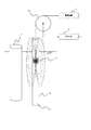
まず、図1に示すように、地中に埋設されている測定対象物である基礎杭1の近傍に磁場の強さを測定するための探査孔2を掘削し、探査孔2の全長にわたってステンレスや塩化ビニール等の非磁性ガイド管3を挿入する。本実施の形態では、探査孔2を基礎杭1と平行(鉛直)に掘削したが、基礎杭1に対して斜めに掘削しても良い。なお、測定対象物である基礎杭1としては、具体的には、杭(鋼杭,場所打ち杭)の他、ケーソン(鋼製,鉄筋コンクリート製)、井筒(鉄筋コンクリート製)、フーチング(鉄筋コンクリート製)、鋼矢板、埋設管(鋼管、鉄筋コンクリート製)等が考えられる。
First, as shown in FIG. 1, an
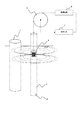
次に、非磁性ガイド管3にコイル等からなる磁場発生装置4を挿入し、磁場発生装置4を探査孔2の軸方向(以下、探査孔2の軸方向を探査軸方向と称す)に移動させながら、電源装置5から磁場発生装置4に電源を供給して磁場を発生させ、基礎杭1を磁化させる。磁場発生装置4によって発生させる磁場の向きは、図1に示すように、探査軸方向でも良く、図2に示すように、探査軸に対して直角方向でも良いが、磁場発生装置4によって探査軸方向に磁場を発生させるようにすると、コイルの長さを長くすることができるため、磁場生成範囲を大きくでき、好適である。なお、本明細書において、「磁場の向き」とは、磁場を発生させている磁石等の磁場発生源のN極とS極とを結ぶ線の向きのことを示し、従って、「探査軸方向に磁場を発生させる」とは、N極とS極とを結ぶ線が探査軸方向と平行である状態の磁石等の磁場発生源によって磁場を発生させることを示す。
Next, a
磁場発生装置4を探査軸方向に移動させるに際し、磁場の向きが変化しないようにすることが必要である。すなわち、磁場発生装置4によって探査軸方向に磁場を発生させる場合には、磁場発生装置4を探査軸方向に位置決めした状態で移動させ、磁場の向きが常に探査軸方向になるように移動させる。なお、探査孔2が鉛直に掘削されている場合には、磁場発生装置4を吊り下げた時に、発生させる磁場の向きが探査軸方向になるように構成すれば良い。
When moving the
また、磁場発生装置4によって探査軸に対して直角方向に磁場を発生させる場合には、磁場発生装置4を探査軸に対して直角方向に位置決めした状態で移動させる必要があり、この場合には、また、探査孔2内に探査軸方向と平行なガイド棒を設置し、当該ガイド棒で磁場発生装置4を探査軸に対して直角方向に位置決めした状態でガイドしながら探査軸方向に移動させるようにすれば良い。
Further, when the
電源装置5から磁場発生装置4に供給する電源としては、直流電流を供給する直流電源と、コンデンサを利用してパルス電流を供給するパルス電源とを使用することができる。電源装置5として直流電源を使用した場合には、一定の直流電流を磁場発生装置4に供給して一定の強さの磁場を発生させた状態で磁場発生装置4を探査軸方向に移動させる。電源装置5としてパルス電源を使用した場合には、プーリー6に接続されたカウンタ7からの深さ情報に基づいて、磁場発生装置4が探査軸方向の所定の深さ毎にパルス電流を磁場発生装置4に供給して磁場を発生させる。
As a power source to be supplied from the power source device 5 to the
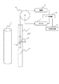
次に、磁場発生装置4を非磁性ガイド管3から抜き取り、図3に示すように、非磁性ガイド管3に3次元磁気センサ8を挿入し、基礎杭1の軸方向、すなわち探査軸方向に深さを変えながらx軸方向、y軸方向、z軸方向の磁場の強さをそれぞれ測定する。基礎杭1に使用されている鉄等の鋼材は、磁場発生装置4によって発生させた磁場によって残留磁気の磁極の向きが揃うため、基礎杭1の周辺の磁場が強くなっている。
Next, the
3次元磁気センサ8は、互いに直交する向き(x軸、y軸、z軸)の磁場の強さを測定可能な、例えば互いに直交する向きに配置された3つのホール素子からなるもので、静止状態で互いに直交する向きの磁場の強さを測定することが可能な構成となっている。なお、ホール素子の替わりにフラックスゲート型センサやSQUID型センサ等を用いることもできる。 The three-dimensional magnetic sensor 8 is composed of three Hall elements arranged in directions orthogonal to each other, for example, which can measure the strength of magnetic fields in directions orthogonal to each other (x axis, y axis, z axis). In this state, it is possible to measure the strengths of magnetic fields in directions orthogonal to each other. Note that a fluxgate type sensor, a SQUID type sensor, or the like can be used instead of the Hall element.
3次元磁気センサ8は、z軸が探査軸方向になるように位置決めされ、x軸およびy軸がz軸と垂直な平面(水平面)上に位置する。なお、3次元磁気センサ8は、吊り下げることによって鉛直方向がz軸になるように構成されており、探査孔2が鉛直に掘削されている場合には、図3に示すように吊り下げるだけでも各軸の位置決めが可能であるが、より精度良く位置決めする場合には、探査孔2内に基礎杭1と平行なガイド棒を設置し、当該ガイド棒でガイドしながらz軸方向を移動させるようにすれば良い。
The three-dimensional magnetic sensor 8 is positioned so that the z-axis is in the search axis direction, and the x-axis and the y-axis are located on a plane (horizontal plane) perpendicular to the z-axis. The three-dimensional magnetic sensor 8 is configured such that the vertical direction becomes the z-axis when suspended, and when the
3次元磁気センサ8からの出力は、増幅器9で増幅され、プーリー6に接続されたカウンタ7からの深さ情報と共にデータ収集器10に入力される。従って、データ収集器10には、深さ毎のx軸方向、y軸方向およびz軸方向の磁場の強さが探査データとして収集されることになる。
The output from the three-dimensional magnetic sensor 8 is amplified by the amplifier 9 and input to the
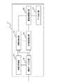
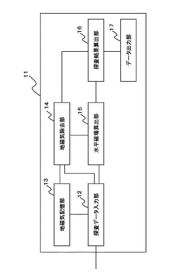
形状解析装置11は、図4を参照すると、データ収集器10からの探査データが入力される探査データ入力部12と、予め測定しておいた地磁気データが記憶される地磁気記憶部13と、地磁気記憶部13に記憶されている地磁気データに基づいて探査データから地磁気を除去する地磁気除去部14と、水平磁場算出部15と、探査結果算出部16と、データ出力部17とからなる。
Referring to FIG. 4, the
探査データ入力部12には、データ収集器10から探査データとして深さ毎のx軸方向の磁場の強さBXと、y軸方向の磁場の強さBYと、z軸方向の磁場の強さBZとが入力される。
Exploration data input unit 12, and strength B X in the x-axis direction of the magnetic field from the
地磁気記憶部13に記憶させる地磁気は、周囲の磁性体から十分離れた位置に3次元磁気センサ8を置き、z軸が鉛直方向になるように調整し、x軸方向、y軸方向、z軸方向の3方向成分の磁場の強さ(μT)をそれぞれ測定し、当該測定結果をそれぞれ地磁気Bx0、By0、Bz0として記憶させておく。また、地磁気記憶部13に記憶させる地磁気としては、探査軸方向の複数箇所でx軸方向、y軸方向、z軸方向の3方向成分の磁場の強さ(μT)をそれぞれ測定し、3方向成分毎の平均値を地磁気Bx0、By0、Bz0として記憶させるようにしても良い。
The geomagnetism stored in the
水平磁場算出部15は、以下に示す数式1によって水平成分の磁場の強さBHを算出する。すなわち、図5に示すように、3次元磁気センサ8が回転してx軸およびy軸が変化しても、x軸方向の磁場の強さBXと、y軸方向の磁場の強さBYとから正確な水平成分の磁場の強さBHを算出する。 The horizontal magnetic field calculation unit 15 calculates the magnetic field strength B H of the horizontal component according to Equation 1 shown below. That is, as shown in FIG. 5, a three-dimensional even x-axis and y-axis magnetic sensor 8 rotates and changes, and strength B X of the magnetic field in the x-axis direction, the strength of the magnetic field in the y-axis direction B An accurate horizontal component magnetic field strength B H is calculated from Y.
地磁気除去部14は、以下に示す式によって水平成分の地磁気Bh0を算出し、地磁気を除去した水平成分の磁場の強さBh=BH−Bh0と、地磁気を除去した鉛直方向の磁場の強さBz=BZ−Bz0を算出する。
The
探査結果算出部16は、地磁気を除去した水平成分の磁場の強さBhと、地磁気を除去した鉛直方向の磁場の強さBzとからtanθ=Bh/Bzを算出する。
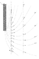
このようにして深さ毎のtanθ=Bh/Bzを算出してプリンタ等のデータ出力部17にグラフや表として出力する。
The exploration
In this way, tan θ = B h / B z for each depth is calculated and output to the
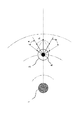
基礎杭1を磁石してみなすと、基礎杭1からは、図6に示すような磁力線がでていることになり、tanθ=Bh/Bzを算出して水平成分の磁場の強さBhと鉛直方向の磁場の強さBzとの比として捉えることにより、磁力線の角度の変化を検出できるため、データ出力部17から出力されるグラフや表には、基礎杭1の先端位置を中心とした明らかな変動が確認でき、基礎杭1の杭長を検出することが可能になる。
When the foundation pile 1 is regarded as a magnet, magnetic lines of force as shown in FIG. 6 are generated from the foundation pile 1, and tan θ = B h / B z is calculated to calculate the horizontal component magnetic field strength B. Since the change in the angle of the magnetic lines of force can be detected by grasping it as the ratio of h and the magnetic field strength Bz in the vertical direction, the graph and table output from the
また、鉛直方向の磁場の強さBzのみでは、基礎杭1と3次元磁気センサ8との離隔が大きいときに誤差が大きくなるが、水平成分の磁場の強さBh、鉛直方向の磁場の強さBzとも同じレベルで磁気量が低下するため、tanθ=Bh/Bzとすれば、磁気量が小さくても精度が良く基礎杭1の先端位置を検出することが可能になる。さらに、tanθ=Bh/Bzとすることで、θ=0で正負が入れ替わり、検出の信頼性が向上する。 In addition, with only the vertical magnetic field strength B z , the error increases when the separation between the foundation pile 1 and the three-dimensional magnetic sensor 8 is large, but the horizontal component magnetic field strength B h , the vertical magnetic field since quantity of magnetism at the same level as the strength B z of drops, if tanθ = B h / B z, it becomes possible amount magnetism detecting the position of the front end of good foundation pile 1 accuracy even small . Furthermore, by setting tan θ = B h / B z , positive and negative are switched when θ = 0, and the detection reliability is improved.
なお、本実施の形態では、3次元磁気センサ8の回転を考慮して水平成分の磁場の強さBHを、x軸方向の磁場の強さBXと、y軸方向の磁場の強さBYとから算出するように構成したが、z軸(鉛直方向)の移動に際して3次元磁気センサ8が回転しないように、すなわちx軸およびy軸が動かないように位置決めすると、地磁気の除去をより正確に行うことができる。 In this embodiment, the strength B H of the magnetic field of the horizontal component in consideration of the rotation of the 3D magnetic sensor 8, and strength B X of the magnetic field in the x-axis direction, of the magnetic field in the y-axis direction strength It is configured to calculate from BY , but if positioning is performed so that the three-dimensional magnetic sensor 8 does not rotate during the movement of the z-axis (vertical direction), that is, the x-axis and the y-axis do not move, the removal of the geomagnetism is performed. It can be done more accurately.
この場合には、地磁気除去部14によって、成分毎に地磁気を除去し、地磁気を除去したx軸方向の磁場の強さBx=BX−Bx0と、地磁気を除去したy軸方向の磁場の強さBy=BY−By0と、地磁気を除去したz軸方向(鉛直方向)の磁場の強さBz=BZ−Bz0をそれぞれ算出し、水平磁場算出部15によって、地磁気を除去したx軸方向の磁場の強さBxと、地磁気を除去したy軸方向の磁場の強さByとから以下に示す式によって水平成分の磁場の強さBhを算出するようにすれば良い。
In this case, the
また、x軸およびy軸が動かないように位置決めした場合には、水平成分の磁場の強さBhを算出することなく、探査結果算出部16において、地磁気を除去したx軸方向の磁場の強さBxもしくは地磁気を除去したy軸方向の磁場の強さByを用いてtanθ=Bx/Bzもしくはtanθ=By/Bzを算出するようにしても良く、この場合には、3次元磁気センサ8の替わりに互いに直交する向き(x軸もしくはy軸、z軸)の磁場の強さを測定可能な2次元磁気センサを用いることができる。
Also, when positioned so as not to move the x and y axes, without calculating the intensity B h of the magnetic field of the horizontal component, the search result in the
以上説明したように、本実施の形態によれば、基礎杭1の近傍で磁場を発生させることによって、基礎杭1の鋼材を一旦磁化させて基礎杭1が有する残留磁気の磁極の方向を揃えた後に、探査軸方向の異なる箇所の磁場の強さをそれぞれ測定することにより、基礎杭が有する残留磁気による磁場を強くした状態で測定することができるため、場所打ち杭等のように鉄筋量が少ない杭や、フーチングによって探査孔2を杭から離れたところに配置しなければならない場合にも、高い検知精度で杭長を特定することができるという効果を奏する。
As described above, according to the present embodiment, by generating a magnetic field in the vicinity of the foundation pile 1, the steel material of the foundation pile 1 is once magnetized to align the direction of the residual magnetic poles of the foundation pile 1. After that, by measuring the magnetic field strength at different locations in the exploration axis direction, it is possible to measure in the state where the magnetic field due to the residual magnetism of the foundation pile is strengthened. Even when there are few piles or when the
さらに、本実施の形態によれば、磁場発生装置4を磁場の方向を一定にした状態で探査軸方向に移動させながら磁場を発生させることによって、基礎杭1を磁化させることにより、強力な磁場を発生させることなく基礎杭1の全体を一旦磁化させることができるため、使用する磁場発生装置4および電源装置5を小型化することができるという効果を奏する。
Furthermore, according to the present embodiment, a strong magnetic field is generated by magnetizing the foundation pile 1 by generating a magnetic field while moving the
さらに、本実施の形態によれば、探査軸方向の所定間隔毎にパルス電流を磁場発生装置4に供給して磁場を発生させることによって、基礎杭1を磁化させることにより、直流電源を用いることなく基礎杭1の全体を一旦磁化させることができるため、使用する磁場発生装置4および電源装置5をさらに小型化することができるという効果を奏する。
Furthermore, according to this embodiment, a DC power source is used by magnetizing the foundation pile 1 by supplying a pulse current to the
なお、本実施の形態では、磁場発生装置4を移動させながら基礎杭1を磁化させるように構成したが、磁場発生装置4によって基礎杭1の全体を磁化させる強力な磁場を発生させることができるならば、磁場発生装置4を固定した状態で基礎杭1を磁化させるようにしても良い。
In the present embodiment, the foundation pile 1 is magnetized while moving the
なお、本発明が上記各実施の形態に限定されず、本発明の技術思想の範囲内において、各実施の形態は適宜変更され得ることは明らかである。また、上記構成部材の数、位置、形状等は上記実施の形態に限定されず、本発明を実施する上で好適な数、位置、形状等にすることができる。なお、各図において、同一構成要素には同一符号を付している。 Note that the present invention is not limited to the above-described embodiments, and it is obvious that the embodiments can be appropriately changed within the scope of the technical idea of the present invention. In addition, the number, position, shape, and the like of the constituent members are not limited to the above-described embodiment, and can be set to a suitable number, position, shape, and the like in practicing the present invention. In each figure, the same numerals are given to the same component.
1 基礎杭
2 探査孔
3 非磁性ガイド管
4 磁場発生装置
5 電源装置
6 プーリー
7 カウンタ
8 3次元磁気センサ
9 増幅器
10 データ収集器
11 形状解析装置
12 探査データ入力部
13 地磁気記憶部
14 地磁気除去部
15 水平磁場算出部
16 探査結果算出部
17 データ出力部
DESCRIPTION OF SYMBOLS 1
Claims (5)
前記測定対象物の近傍で磁場を発生させることによって、前記測定対象物を一旦磁化させて前記測定対象物が有する残留磁気の磁極の方向を揃えた後に、探査軸方向の異なる箇所の磁場の強さをそれぞれ測定することを特徴とする磁気探査方法。 A magnetic exploration method for detecting the tip position of the measurement object in a non-contact manner by performing a magnetic exploration in the vicinity of the measurement object including a steel material embedded in the ground,
By generating a magnetic field in the vicinity of the measurement object, the measurement object is once magnetized to align the direction of the remanent magnetic pole of the measurement object, and then the magnetic field strength at different locations in the search axis direction is increased. A magnetic exploration method characterized by measuring each thickness.
The three-dimensional magnetic sensor capable of measuring the magnetic amounts of the x-axis, y-axis and z-axis orthogonal to each other is moved in the z-axis direction in a state where the z-axis is positioned in the search axis direction, so that the search axis directions are different. 5. The magnetic exploration method according to claim 1, wherein the magnetic field strength at each location is measured.
Priority Applications (1)
| Application Number | Priority Date | Filing Date | Title |
|---|---|---|---|
| JP2004104440A JP2005291802A (en) | 2004-03-31 | 2004-03-31 | Magnetic exploration method |
Applications Claiming Priority (1)
| Application Number | Priority Date | Filing Date | Title |
|---|---|---|---|
| JP2004104440A JP2005291802A (en) | 2004-03-31 | 2004-03-31 | Magnetic exploration method |
Publications (1)
| Publication Number | Publication Date |
|---|---|
| JP2005291802A true JP2005291802A (en) | 2005-10-20 |
Family
ID=35324908
Family Applications (1)
| Application Number | Title | Priority Date | Filing Date |
|---|---|---|---|
| JP2004104440A Pending JP2005291802A (en) | 2004-03-31 | 2004-03-31 | Magnetic exploration method |
Country Status (1)
| Country | Link |
|---|---|
| JP (1) | JP2005291802A (en) |
Cited By (4)
| Publication number | Priority date | Publication date | Assignee | Title |
|---|---|---|---|---|
| JP5165808B1 (en) * | 2012-08-27 | 2013-03-21 | 有限会社沖縄基礎開発 | Differential magnetic exploration system |
| JP2018021444A (en) * | 2016-06-01 | 2018-02-08 | バウアー マシーネン ゲーエムベーハー | Method and apparatus for extracting pile elements from the ground |
| CN114371515A (en) * | 2021-03-08 | 2022-04-19 | 天津商业大学 | Device and method for auxiliary measurement of horizontal component of geomagnetic field by using smart phone |
| CN118327066A (en) * | 2024-06-13 | 2024-07-12 | 上海勘测设计研究院有限公司 | Flood control wall foundation detection method |
-
2004
- 2004-03-31 JP JP2004104440A patent/JP2005291802A/en active Pending
Cited By (4)
| Publication number | Priority date | Publication date | Assignee | Title |
|---|---|---|---|---|
| JP5165808B1 (en) * | 2012-08-27 | 2013-03-21 | 有限会社沖縄基礎開発 | Differential magnetic exploration system |
| JP2018021444A (en) * | 2016-06-01 | 2018-02-08 | バウアー マシーネン ゲーエムベーハー | Method and apparatus for extracting pile elements from the ground |
| CN114371515A (en) * | 2021-03-08 | 2022-04-19 | 天津商业大学 | Device and method for auxiliary measurement of horizontal component of geomagnetic field by using smart phone |
| CN118327066A (en) * | 2024-06-13 | 2024-07-12 | 上海勘测设计研究院有限公司 | Flood control wall foundation detection method |
Similar Documents
| Publication | Publication Date | Title |
|---|---|---|
| Breiner | Applications manual for portable magnetometers | |
| Gibson | Application of resistivity and magnetometry geophysical techniques for near-surface investigations in karstic terranes in Ireland | |
| JPH0637825B2 (en) | Mooring equipment | |
| CN109883450A (en) | Method for positioning magnetic marker of detector in buried steel pipeline | |
| CN102877830A (en) | Underground orientation method based on rotating magnetic field | |
| Bevan et al. | Magnetic exploration of archaeological sites | |
| Narkhov et al. | Novel quantum NMR magnetometer non-contact defectoscopy and monitoring technique for the safe exploitation of gas pipelines | |
| Herwanger et al. | 3-D inversions of magnetic gradiometer data in archeological prospecting: Possibilities and limitations | |
| US11566511B2 (en) | Imaging inside a structure using magneto quasistatic fields | |
| CN113050182B (en) | A geomagnetic field observation method and system in water areas | |
| JP2005291802A (en) | Magnetic exploration method | |
| KR100264630B1 (en) | Rebar detection and detection method in concrete foundation piles by measuring 3-axis magnetic field in borehole | |
| CN113687425B (en) | Electric prospecting method and system | |
| JP4164747B2 (en) | Magnetic exploration method | |
| JP2005291818A (en) | Penetration tool and magnetic exploration method used for magnetic exploration | |
| JP2005291812A (en) | Magnetic exploration method | |
| JP4164746B2 (en) | Penetration tool and magnetic exploration method used for magnetic exploration | |
| CN214225443U (en) | Instrument fixing device for magnetic measurement in water area | |
| CN102621583B (en) | The method of three-component gradiometry in magnetic field to the outer magnetic orientation of well, location in well | |
| JP2010078585A (en) | Method for finding the location of buried magnetic object | |
| JPH05281366A (en) | Position display device for metal bodies embedded in concrete | |
| CN107728220A (en) | A kind of buried abandoned well artificial magnetization device and detection method | |
| Kristjánsson | Notes on paleomagnetic sampling in Iceland | |
| JP2004347533A (en) | Method and device for magnetic prospecting | |
| CN206863252U (en) | Calibrating installation for magnetic logger |
Legal Events
| Date | Code | Title | Description |
|---|---|---|---|
| A621 | Written request for application examination |
Free format text: JAPANESE INTERMEDIATE CODE: A621 Effective date: 20060724 |
|
| A977 | Report on retrieval |
Effective date: 20070921 Free format text: JAPANESE INTERMEDIATE CODE: A971007 |
|
| A131 | Notification of reasons for refusal |
Effective date: 20080902 Free format text: JAPANESE INTERMEDIATE CODE: A131 |
|
| A02 | Decision of refusal |
Effective date: 20090106 Free format text: JAPANESE INTERMEDIATE CODE: A02 |