JP2005291818A - Penetration tool and magnetic exploration method used for magnetic exploration - Google Patents
Penetration tool and magnetic exploration method used for magnetic exploration Download PDFInfo
- Publication number
- JP2005291818A JP2005291818A JP2004104901A JP2004104901A JP2005291818A JP 2005291818 A JP2005291818 A JP 2005291818A JP 2004104901 A JP2004104901 A JP 2004104901A JP 2004104901 A JP2004104901 A JP 2004104901A JP 2005291818 A JP2005291818 A JP 2005291818A
- Authority
- JP
- Japan
- Prior art keywords
- magnetic
- magnetic field
- exploration
- rod
- penetrating
- Prior art date
- Legal status (The legal status is an assumption and is not a legal conclusion. Google has not performed a legal analysis and makes no representation as to the accuracy of the status listed.)
- Pending
Links
- 230000005291 magnetic effect Effects 0.000 title claims abstract description 220
- 238000000034 method Methods 0.000 title claims abstract description 22
- 230000035515 penetration Effects 0.000 title abstract description 16
- 230000000149 penetrating effect Effects 0.000 claims abstract description 52
- 238000005259 measurement Methods 0.000 claims description 17
- 229910000831 Steel Inorganic materials 0.000 claims description 9
- 239000010959 steel Substances 0.000 claims description 9
- 239000000463 material Substances 0.000 claims description 6
- 239000000696 magnetic material Substances 0.000 claims description 3
- 238000001514 detection method Methods 0.000 abstract description 11
- 230000005389 magnetism Effects 0.000 abstract description 5
- 230000003014 reinforcing effect Effects 0.000 abstract description 4
- 238000004364 calculation method Methods 0.000 description 7
- 238000010586 diagram Methods 0.000 description 7
- 238000013215 result calculation Methods 0.000 description 6
- 239000011150 reinforced concrete Substances 0.000 description 4
- 238000006073 displacement reaction Methods 0.000 description 3
- 229910000838 Al alloy Inorganic materials 0.000 description 2
- 230000000694 effects Effects 0.000 description 2
- 239000010935 stainless steel Substances 0.000 description 2
- 229910001256 stainless steel alloy Inorganic materials 0.000 description 2
- 241000238366 Cephalopoda Species 0.000 description 1
- 230000015572 biosynthetic process Effects 0.000 description 1
- 239000000470 constituent Substances 0.000 description 1
- 238000010276 construction Methods 0.000 description 1
- 238000005553 drilling Methods 0.000 description 1
- 239000004576 sand Substances 0.000 description 1
- 238000011144 upstream manufacturing Methods 0.000 description 1
- 238000004804 winding Methods 0.000 description 1
Images
Landscapes
- Geophysics And Detection Of Objects (AREA)
- Measurement Of Length, Angles, Or The Like Using Electric Or Magnetic Means (AREA)
Abstract
【課題】 本発明は、探査孔を掘削することなく磁気探査を行うことができ、作業効率を向上させることができると共に、場所打ち杭等のように鉄筋量が少ない杭や、フーチングによって基礎杭から離れたところを探査しなければならない場合にも、地磁気に影響されることなく高い検知精度で杭長を特定することができる磁気探査に用いる貫入具および磁気探査方法を提供することを課題とする。
【解決手段】 貫入先端ロッド1もしくは継ぎロッド2の中空部に取り付けられた磁場発生装置8によって、基礎杭3を磁化させ、貫入先端ロッド1もしくは継ぎロッド2の中空部に取り付けられた3次元磁気センサ6によって少なくとも探査軸方向の磁場の強さを測定するように構成し、貫入先端ロッド1および継ぎロッド2を圧入しながら探査軸方向の異なる箇所、すなわち深さ毎の磁場の強さを探査データとして測定する。
【選択図】 図4
PROBLEM TO BE SOLVED: To perform magnetic exploration without excavating an exploration hole, improve work efficiency, and have a small amount of reinforcing bars such as cast-in-place piles or foundation piles by footing. It is an object to provide a penetrating tool and a magnetic exploration method used for magnetic exploration that can identify a pile length with high detection accuracy without being affected by geomagnetism even when it is necessary to explore a place away from To do.
Three-dimensional magnetism in which a foundation pile 3 is magnetized by a magnetic field generator 8 attached to a hollow portion of a penetrating tip rod 1 or a joint rod 2 and attached to a hollow portion of the penetrating tip rod 1 or the joint rod 2. The sensor 6 is configured to measure at least the strength of the magnetic field in the direction of the search axis, and searches for different locations in the direction of the search axis, that is, the strength of the magnetic field at each depth, while pressing the penetration tip rod 1 and the joint rod 2. Measure as data.
[Selection] Figure 4
Description
本発明は、磁気探査に用いる貫入具および磁気探査方法に関し、特に基礎杭等の地中に埋設された杭の先端位置を検出する磁気探査に用いる貫入具および磁気探査方法に関する。 The present invention relates to a penetrating tool and a magnetic exploration method used for magnetic exploration, and more particularly to an penetrating tool and a magnetic exploration method used for magnetic exploration for detecting a tip position of a pile embedded in the ground such as a foundation pile.
施行年度の古い構造物の耐震性判定のためや、老朽化した構造物の更新のためには、基礎杭の杭長を確認しておく必要があるが、図面等が存在しない場合には、基礎杭の杭長を調査しなければならない。 It is necessary to confirm the pile length of the foundation pile for the seismic assessment of the old structure in the year of enforcement or for the replacement of an aged structure. The pile length of the foundation pile must be investigated.
従来、基礎杭の杭長を調査には、両コイル型磁気傾度計を用いた磁気探査方法が行われている。磁気探査方法は、基礎杭の残留磁気や地球磁場による感応磁気を測定することによって杭長を特定するもので、ロータリーボーリング等によって測定対象の基礎杭の近傍に探査孔を掘削し、当該探査孔に両コイル型磁気傾度計を挿入して一定速度で移動させることによって磁気傾度、すなわち磁場の強さの変化率を測定し、杭長を特定する(例えば、非特許文献1参照)。 Conventionally, in order to investigate the pile length of a foundation pile, a magnetic exploration method using a double coil type magnetic inclinometer has been performed. The magnetic exploration method specifies the pile length by measuring the residual magnetism of the foundation pile and the sensitive magnetism due to the earth's magnetic field. The exploration hole is excavated in the vicinity of the foundation pile to be measured by rotary boring, etc. The magnetic gradient, that is, the rate of change in the strength of the magnetic field is measured by inserting a double coil type magnetic inclinometer and moving at a constant speed, and the pile length is specified (for example, see Non-Patent Document 1).
しかしながら、従来の磁気探査方法では、ロータリーボーリング等によって所定深さの探査孔を掘削する必要があり、大掛かりな機械を必要とすると共に、磁気探査後に探査孔を埋め戻す必要があるため、作業が煩雑になってしまうという問題点があった。また、砂層等の緩い地層に探査孔を掘削する場合には、孔壁の崩落を防ぐために非磁性ガイド管を随時挿入する必要があり、作業効率が低下してしまうという問題点があった。 However, in the conventional magnetic exploration method, it is necessary to excavate an exploration hole of a predetermined depth by rotary boring or the like, and a large-scale machine is required and the exploration hole needs to be backfilled after magnetic exploration. There was a problem of becoming complicated. Further, when excavating a survey hole in a loose formation such as a sand layer, it is necessary to insert a non-magnetic guide tube as needed to prevent the collapse of the hole wall, resulting in a problem that work efficiency is lowered.
さらに、従来の磁気探査方法では、H型鋼杭等の比較的鋼材量が多く、残留磁気量が大きい対象物に対しては実績が得られているものの、場所打ち杭等のように鉄筋量が少ない杭や、フーチングによって基礎杭から離れたところで探査しなければならない場合には、地磁気の影響で高い検知精度が期待できないという問題点があった。
本発明は斯かる問題点を鑑みてなされたものであり、その目的とするところは、探査孔を掘削することなく磁気探査を行うことができ、作業効率を向上させることができると共に、場所打ち杭等のように鉄筋量が少ない杭や、フーチングによって基礎杭から離れたところを探査しなければならない場合にも、地磁気に影響されることなく高い検知精度で杭長を特定することができる磁気探査に用いる貫入具および磁気探査方法を提供する点にある。 The present invention has been made in view of such problems, and the object of the present invention is to perform magnetic exploration without excavating the exploration hole, improve work efficiency, Magnetics that can specify pile length with high detection accuracy without being affected by geomagnetism, even when piles with a small amount of reinforcing bars, such as piles, or when it is necessary to explore places away from the foundation pile by footing It is the point which provides the penetration tool and magnetic exploration method which are used for exploration.
本発明は上記課題を解決すべく、以下に掲げる構成とした。
請求項1記載の発明の要旨は、鋼材を含む測定対象物の近傍の磁場の強さを測定して、前記測定対象物の先端位置を非接触で検出する磁気探査に用いる貫入具であって、非磁性体で構成され、突状の先端部が形成された筒状体である貫入先端ロッドと、該貫入先端ロッドに継ぎ足される非磁性体で構成された筒状体である継ぎロッドと、前記貫入先端ロッドもしくは前記継ぎロッドの中空部に取り付けられ、磁場の強さを測定可能な磁気センサと、前記貫入先端ロッドもしくは前記継ぎロッドの中空部に取り付けられ、前記測定対象物を磁化させる磁場を発生させる磁場発生手段とを具備することを特徴とする磁気探査に用いる貫入具に存する。
また請求項2記載の発明の要旨は、前記磁場発生手段は、探査軸方向に磁場を発生させるように前記貫入先端ロッドもしくは前記継ぎロッドの中空部に取り付けられていることを特徴とする請求項1記載の磁気探査に用いる貫入具に存する。
また請求項3記載の発明の要旨は、請求項1又は2記載の磁気探査に用いる貫入具を用いて磁気探査を行う磁気探査方法であって、前記磁場発生手段によって発生された磁場によって前記測定対象物を磁化させた状態で、前記磁気センサによって磁場の強さを測定することを特徴とする磁気探査方法に存する。
また請求項4記載の発明の要旨は、請求項1又は2記載の磁気探査に用いる貫入具を用いて磁気探査を行う磁気探査方法であって、前記磁場発生手段によって発生された磁場によって前記測定対象物を一旦磁化させて前記測定対象物が有する残留磁気の磁極の方向を揃えた後に、前記磁気センサによって磁場の強さを測定することを特徴とする磁気探査方法に存する。
In order to solve the above problems, the present invention has the following configuration.
The gist of the invention described in
According to a second aspect of the present invention, the magnetic field generating means is attached to the hollow portion of the penetrating tip rod or the connecting rod so as to generate a magnetic field in the direction of the search axis. It exists in the penetration tool used for the magnetic exploration of 1 description.
The gist of the invention described in
According to a fourth aspect of the present invention, there is provided a magnetic exploration method for performing magnetic exploration using the penetrating tool used for magnetic exploration according to
本発明の磁気探査に用いる貫入具および磁気探査方法は、貫入先端ロッドもしくは継ぎロッドの中空部に取り付けられた磁場発生手段によって、測定対象物を磁化させ、貫入先端ロッドもしくは継ぎロッドの中空部に取り付けられた磁気センサによって少なくとも探査軸方向の磁場の強さを測定するように構成することにより、貫入先端ロッドおよび継ぎロッドを圧入するだけで、貫入先端ロッドもしくは継ぎロッドの中空部に取り付けられた磁気センサによって磁場の強さを測定できるため、探査孔を掘削することなく磁気探査を行うことができ、作業効率を向上させることができると共に、測定対象物を磁化させて測定対象物からの磁場を強くすることができるため、場所打ち杭等のように鉄筋量が少ない杭や、フーチングによって測定対象物から離れたところで探査しなければならない場合にも、地磁気に影響されることなく測定対象物からの磁場の強さを測定することができ、高い検知精度で杭長を特定することができるという効果を奏する。 The penetrating tool and the magnetic exploration method used in the magnetic exploration of the present invention magnetize the measurement object by the magnetic field generating means attached to the hollow portion of the penetrating tip rod or joint rod, and to the hollow portion of the penetrating tip rod or joint rod. By mounting at least the penetrating tip rod and the connecting rod, it is attached to the hollow portion of the penetrating tip rod or the connecting rod by configuring the magnetic sensor to measure at least the strength of the magnetic field in the exploration axis direction. Since the magnetic field strength can be measured by the magnetic sensor, magnetic exploration can be performed without drilling the exploration hole, the work efficiency can be improved, and the magnetic field from the measurement object can be magnetized. Measured with piles with a small amount of reinforcing bars, such as cast-in-place piles, and footing Even when it is necessary to explore at a distance from the object, the strength of the magnetic field from the measurement object can be measured without being affected by geomagnetism, and the pile length can be specified with high detection accuracy. There is an effect.
以下、本発明の実施の形態を図面に基づいて詳細に説明する。 Hereinafter, embodiments of the present invention will be described in detail with reference to the drawings.
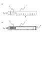
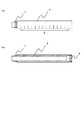
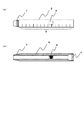
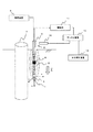
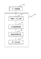
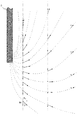
図1は、本発明に係る磁気探査に用いる貫入具の実施の形態の貫入先端ロッドの構成を示す図であり、(a)は、側面図であり、(b)は、縦断面図である。図2は、本発明に係る磁気探査に用いる貫入具の実施の形態の継ぎロッドの構成を示す図であり、(a)は、側面図であり、(b)は、縦断面図である。図3は、中空部分に磁場発生装置が取り付けられている図2に示す継ぎロッドの構成を示す図であり、図4は、本発明に係る磁気探査方法の実施の形態で使用する機器構成を示す図であり、図5は、図4に示す形状解析装置の構成を示すブロック図であり、図6は、図4に示す水平磁場算出部における水平磁場の算出方法を説明するための図であり、図7は、図4に示す探査結果算出部において算出された探査結果を説明するための図である。
である。
FIG. 1 is a diagram showing a configuration of a penetrating tip rod of an embodiment of a penetrating tool used for magnetic exploration according to the present invention, (a) is a side view, and (b) is a longitudinal sectional view. . 2A and 2B are diagrams showing the configuration of the joint rod of the embodiment of the penetrating tool used for magnetic exploration according to the present invention, wherein FIG. 2A is a side view and FIG. 2B is a longitudinal sectional view. FIG. 3 is a diagram showing a configuration of the joint rod shown in FIG. 2 in which a magnetic field generator is attached to the hollow portion, and FIG. 4 shows a configuration of equipment used in the embodiment of the magnetic exploration method according to the present invention. FIG. 5 is a block diagram showing the configuration of the shape analysis apparatus shown in FIG. 4, and FIG. 6 is a diagram for explaining a horizontal magnetic field calculation method in the horizontal magnetic field calculation unit shown in FIG. FIG. 7 is a diagram for explaining the search results calculated by the search result calculation unit shown in FIG.
It is.
本実施の形態では、探査孔を掘削する替わりに、図1に示す貫入先端ロッド1と、図2および図3に示す継ぎロッド2とからなる貫入具を、図4に示すように、測定対象物である基礎杭3の近傍に圧入させることによって磁気探査を行う。なお、測定対象の基礎杭3としては、杭(鋼杭,場所打ち杭)の他、ケーソン(鋼製,鉄筋コンクリート製)、井筒(鉄筋コンクリート製)、フーチング(鉄筋コンクリート製)、鋼矢板、埋設管(鋼管、鉄筋コンクリート製)が考えられる。
In this embodiment, instead of excavating the exploration hole, the penetrating tool comprising the
貫入先端ロッド1は、図1を参照すると、ステンレス鋼製、アルミ合金製等の非磁性体で構成され、突状の先端部が形成されている筒状体であり、後端部には、継ぎロッド2を継ぎ足すための雌ネジ4が形成されている。また、外周には、目盛り5が軸方向に等間隔に設けられている。なお、本実施の形態で使用する貫入先端ロッド1の先端角は、60°とし、底面積は、10cm2程度とする。
Referring to FIG. 1, the penetrating
貫入先端ロッド1の中空部分には、互いに直交する向き(x軸、y軸、z軸)の磁場の強さを測定可能な3次元磁気センサ6が、z軸が貫入先端ロッド1の軸方向と一致するように取り付けられている(以下、貫入先端ロッド1の軸方向を探査軸方向と称す)。3次元磁気センサ6は、例えば互いに直交する向きに配置された3つのホール素子からなるもので、静止状態で互いに直交する向きの磁場の強さを測定することが可能な構成となっている。なお、ホール素子の替わりにフラックスゲート型センサやSQUID型センサ等を用いることもできる。
In the hollow portion of the
継ぎロッド2は、図2を参照すると、ステンレス鋼製、アルミ合金製等の非磁性体で構成された筒状体であり、先端部には、貫入先端ロッド1および前段の継ぎロッド2の後端部と螺合する雄ネジ7が形成されており、後端部には、後段の継ぎロッド2を継ぎ足すための雌ネジ4が形成されている。また、外周には、目盛り5が軸方向に等間隔に設けられている。
Referring to FIG. 2, the
継ぎロッド2は、複数個用意され、継ぎ足して使用するものであるが、複数個の継ぎロッド2の内のいずれかには、図3に示すように、中空部分に、基礎杭3を磁化させるためのコイル等からなる磁場発生装置8が、発生させる磁場の向きが貫入先端ロッド1の軸方向と一致するように取り付けられている。なお、本明細書において、「磁場の向き」とは、磁場を発生させている磁石等の磁場発生源のN極とS極とを結ぶ線の向きのことを示す。
A plurality of
磁気探査に際して、図4に示すように、貫入先端ロッド1に磁場発生装置8が取り付けられている継ぎロッド2を繋ぎ、測定対象物である基礎杭3の近傍に継ぎロッド2を継ぎ足しながら鉛直に圧入していく。なお、貫入先端ロッド1および継ぎロッド2の圧入には、パイプ(細径鋼管等)を貫入する既存の圧入機を使用することができる。また、貫入先端ロッド1に設けられた3次元磁気センサ6からの出力ケーブルと、継ぎロッド2に設けられた磁場発生装置8に電流を供給する電源ラインとは、継ぎ足す継ぎロッド2を貫通させる必要があるため、コネクタ等で一端切り離すことができるようになっている。
In the magnetic exploration, as shown in FIG. 4, the
磁場発生装置8と3次元磁気センサ6との距離は、3次元磁気センサ6によって磁場を測定するに際し、磁化された基礎杭3からの磁場が磁場発生装置8で発生させた磁場に埋もれてしまわないように、基礎杭3と貫入先端ロッド1(3次元磁気センサ6)との距離の少なくとも2倍以上に設定する。貫入先端ロッド1に磁場発生装置8が取り付けられている継ぎロッド2を繋いだだけでは、磁場発生装置8と3次元磁気センサ6との距離が基礎杭3と貫入先端ロッド1(3次元磁気センサ6)との距離の2倍以上にならない場合には、貫入先端ロッド1と、磁場発生装置8が取り付けられている継ぎロッド2との間に、磁場発生装置8が取り付けられていない継ぎロッド2を繋ぐようにすれば良い。
The distance between the
また、磁場発生装置8によって発生させる磁場の強さは、3次元磁気センサ6によって磁場を測定するに際し、地磁気の影響を無視できる程度に設定される。すなわち、日本付近の地磁気の強さは、50,000(nT)程度であり、3次元磁気センサ6によって測定される磁場の強さが0.2(mT)=200,000(nT)以上になるように磁場発生装置8によって発生させる磁場の強さを設定し、地磁気の影響を減少させる。
The intensity of the magnetic field generated by the
磁場発生装置8には、図4に示すように、電源ラインを介して電源装置9から電流が供給されるが、電源装置9から磁場発生装置8に供給する電源としては、直流電流を供給する直流電源と、交流電流を供給する交流電源とを使用することができる。電源装置9として直流電源を使用した場合には、一定の直流電流を磁場発生装置8に供給して一定の強さの磁場を発生させた状態で、貫入先端ロッド1および継ぎロッド2の圧入に伴い磁場発生装置8を探査軸方向に移動させる。また、電源装置9として交流電源を使用した場合には、磁場発生装置8によって発生される磁場の強さが周期的に変動すると共に、磁場の向きが周期的に反転することになるが、周期性が存在するため、測定結果を信号処理することによって所望の磁場を測定することができる。
As shown in FIG. 4, the
貫入先端ロッド1および継ぎロッド2の外周に設けられた目盛り5を検出するための目盛り検出センサ10を設置し、貫入先端ロッド1および継ぎロッド2の圧入に並行して、目盛り検出センサ10による目盛り検出タイミングでx軸方向、y軸方向、z軸方向の磁場の強さをそれぞれ測定していく。すなわち、3次元磁気センサ6からの出力は、増幅器11で増幅され、目盛り検出センサ10による目盛り検出タイミングでデータ収集器12に入力される。従って、データ収集器12には、深さ(目盛り5)毎のx軸方向、y軸方向およびz軸方向の磁場の強さが探査データとして収集されることになる。
A
データ収集器12に収集された探査データは、形状解析装置13によって解析され、形状解析装置13は、図5を参照すると、データ収集器12からの探査データが入力される探査データ入力部14と、水平磁場算出部15と、探査結果算出部16と、データ出力部17とからなる。
The exploration data collected by the
探査データ入力部14には、データ収集器12から探査データとして深さ毎のx軸方向の磁場の強さBXと、y軸方向の磁場の強さBYと、z軸方向の磁場の強さBZとが入力される。
The survey
水平磁場算出部15は、以下に示す数式1によって水平成分の磁場の強さBHを算出する。すなわち、図6に示すように、3次元磁気センサ6が回転してx軸およびy軸が変化しても、x軸方向の磁場の強さBXと、y軸方向の磁場の強さBYとから正確な水平成分の磁場の強さBHを算出する。
The horizontal magnetic
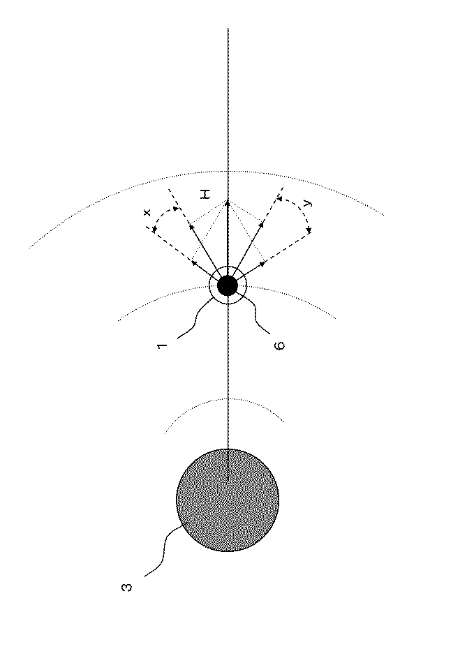
探査結果算出部16は、水平成分の磁場の強さBHと、鉛直方向(z軸方向)の磁場の強さBZとからtanθ=BH/BZを算出する。
このようにして深さ毎のtanθ=BH/BZを算出してプリンタ等のデータ出力部17にグラフや表として出力する。
The exploration
In this way, tan θ = B H / B Z for each depth is calculated and output to the
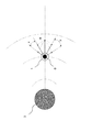
磁化された基礎杭3を磁石してみなすと、基礎杭3からは、図7に示すような磁力線がでていることになり、tanθ=BH/BZを算出して水平成分の磁場の強さBHと鉛直方向の磁場の強さBZとの比として捉えることにより、磁力線の角度の変化を検出できるため、データ出力部17から出力されるグラフや表には、基礎杭3の先端位置を中心とした明らかな変動が確認でき、基礎杭3の杭長を検出することが可能になる。
When the
なお、本実施の形態では、3次元磁気センサ6によってx軸方向、y軸方向およびz軸方向の磁場の強さを測定するようにしたが、z軸方向の磁場の強さのみを測定する磁気センサを用いても良い。磁場発生装置8によって発生された磁場によって地磁気の影響が弱められているので、z軸方向の磁場の強さBzが0になる深さ、すなわち、磁化された基礎杭3からの探査軸方向の磁場が反転している深さに基づいて基礎杭3の杭長を検出することが可能である。
In the present embodiment, the magnetic field strength in the x-axis direction, the y-axis direction, and the z-axis direction is measured by the three-dimensional
さらに、本実施の形態では、3次元磁気センサ6の回転を考慮して水平成分の磁場の強さBHを、x軸方向の磁場の強さBXと、y軸方向の磁場の強さBYとから算出するように構成したが、z軸(鉛直方向)の移動に際して3次元磁気センサ6が回転しないように、すなわちx軸およびy軸が動かないように位置決めすると、水平成分の磁場の強さBHを算出することなく、探査結果算出部16において、x軸方向の磁場の強さBXもしくはy軸方向の磁場の強さBYを用いてtanθ=BX/BZもしくはtanθ=BY/BZを算出するようにしても良く、この場合には、3次元磁気センサ6の替わりに互いに直交する向き(x軸もしくはy軸、z軸)の磁場の強さを測定可能な2次元磁気センサを用いることができる。
Furthermore, in the present embodiment, taking into account the rotation of the three-dimensional
次に、本発明の他の実施の形態について図8に基づいて詳細に説明する。
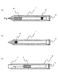
図8は、本発明に係る磁気探査に用いる貫入具の他の実施の形態の構成を示す縦断面図である。
Next, another embodiment of the present invention will be described in detail with reference to FIG.
FIG. 8 is a longitudinal sectional view showing the configuration of another embodiment of the penetrating tool used for magnetic exploration according to the present invention.
図8(a)には、貫入先端ロッド1の中空部分に、3次元磁気センサ6と、磁場発生装置8とが取り付けられている。このように、磁場発生装置8と3次元磁気センサ6との距離を、基礎杭3と3次元磁気センサ6との距離の少なくとも2倍以上に設定できる場合には、同一のロッド(貫入先端ロッド1もしくは継ぎロッド2)に3次元磁気センサ6と磁場発生装置8とを取り付けるようにしても良い。
In FIG. 8A, a three-dimensional
また、図8(b)に示すように、貫入先端ロッド1の中空部分に磁場発生装置8を取り付けると共に、図8(c)に示すように、継ぎロッド2の中空部分に3次元磁気センサ6を取り付けるようにしても良い。すなわち、磁場発生装置8と3次元磁気センサ6との上下位置の関係は、どちらが上でも良い。
8B, a
以上説明したように、本実施の形態によれば、貫入先端ロッド1もしくは継ぎロッド1の中空部に取り付けられた磁場発生装置8によって、基礎杭3を磁化させ、貫入先端ロッド1もしくは継ぎロッド2の中空部に取り付けられた3次元磁気センサ6によって少なくとも探査軸方向の磁場の強さを測定するように構成することにより、貫入先端ロッド1および継ぎロッド2を圧入するだけで、貫入先端ロッド1もしくは継ぎロッド2の中空部に取り付けられた3次元磁気センサ6によって磁場の強さを測定できるため、探査孔を掘削することなく磁気探査を行うことができ、作業効率を向上させることができると共に、基礎杭3を磁化させて基礎杭3からの磁場を強くすることができるため、場所打ち杭等のように鉄筋量が少ない杭や、フーチングによって基礎杭3から離れたところで探査しなければならない場合にも、地磁気に影響されることなく基礎杭3からの磁場の強さを測定することができ、高い検知精度で杭長を特定することができるという効果を奏する。
As described above, according to the present embodiment, the
なお、本実施の形態では、貫入先端ロッド1および継ぎロッド2の外周に設けた目盛り5によって深さを検知するように構成しているが、巻き取り式変位計(継ぎロッド2の長さを1mとした場合、1m計測用の変位計)を押し込み(圧入)機械本体に設置し、ロッドの押し込み(圧入)量を電気的に検出することによって深さを検知するように構成しても良い。この場合には、継ぎロッド2の継ぎ足し工程で毎回、変位計の目盛り変えを併せて実施する。
In the present embodiment, the depth is detected by the
また、本実施の形態では、磁場発生装置8によって基礎杭3を磁化させた状態で磁場を測定するように構成したが、磁場発生装置8によって基礎杭3を一旦磁化させた後に、磁場発生装置8による磁場の発生を止めて、磁場を測定するようにしても良い。この場合にも、基礎杭3が有する残留磁気の磁極の方向が一旦磁化されることにより揃えられるため、残留磁気による磁場が強くなり、高い精度で検出することが可能になる。
In this embodiment, the magnetic field is measured in a state where the
なお、本発明が上記各実施の形態に限定されず、本発明の技術思想の範囲内において、各実施の形態は適宜変更され得ることは明らかである。また、上記構成部材の数、位置、形状等は上記実施の形態に限定されず、本発明を実施する上で好適な数、位置、形状等にすることができる。なお、各図において、同一構成要素には同一符号を付している。 Note that the present invention is not limited to the above-described embodiments, and it is obvious that the embodiments can be appropriately changed within the scope of the technical idea of the present invention. In addition, the number, position, shape, and the like of the constituent members are not limited to the above-described embodiment, and can be set to a suitable number, position, shape, and the like in practicing the present invention. In each figure, the same numerals are given to the same component.
1 貫入先端ロッド
2 継ぎロッド
3 基礎杭
4 雌ネジ
5 目盛り
6 3次元磁気センサ
7 雄ネジ
8 磁場発生装置
9 電源装置
10 目盛り検出センサ
11 増幅器
12 データ収集器
13 形状解析装置
14 探査データ入力部
15 水平磁場算出部
16 探査結果算出部
17 データ出力部
DESCRIPTION OF
Claims (4)
非磁性体で構成され、突状の先端部が形成された筒状体である貫入先端ロッドと、
該貫入先端ロッドに継ぎ足される非磁性体で構成された筒状体である継ぎロッドと、
前記貫入先端ロッドもしくは前記継ぎロッドの中空部に取り付けられ、磁場の強さを測定可能な磁気センサと、
前記貫入先端ロッドもしくは前記継ぎロッドの中空部に取り付けられ、前記測定対象物を磁化させる磁場を発生させる磁場発生手段とを具備することを特徴とする磁気探査に用いる貫入具。 An intruder used for magnetic exploration that measures the strength of a magnetic field in the vicinity of a measurement object including a steel material and detects the tip position of the measurement object in a non-contact manner,
A penetrating tip rod that is a cylindrical body formed of a non-magnetic material and having a protruding tip portion formed thereon;
A joint rod that is a cylindrical body composed of a non-magnetic material joined to the penetrating tip rod;
A magnetic sensor attached to the hollow portion of the penetrating tip rod or the joint rod and capable of measuring the strength of the magnetic field;
A penetrating tool used for magnetic exploration, comprising: a magnetic field generating means for generating a magnetic field for magnetizing the measurement object, attached to a hollow portion of the penetrating tip rod or the joint rod.
前記磁場発生手段によって発生された磁場によって前記測定対象物を磁化させた状態で、前記磁気センサによって磁場の強さを測定することを特徴とする磁気探査方法。 A magnetic exploration method for performing magnetic exploration using the penetrating tool used for magnetic exploration according to claim 1 or 2,
A magnetic exploration method characterized by measuring the strength of a magnetic field by the magnetic sensor in a state where the measurement object is magnetized by a magnetic field generated by the magnetic field generation means.
前記磁場発生手段によって発生された磁場によって前記測定対象物を一旦磁化させて前記測定対象物が有する残留磁気の磁極の方向を揃えた後に、前記磁気センサによって磁場の強さを測定することを特徴とする磁気探査方法。
A magnetic exploration method for performing magnetic exploration using the penetrating tool used for magnetic exploration according to claim 1 or 2,
The magnetic field is measured by the magnetic sensor after the measurement object is once magnetized by the magnetic field generated by the magnetic field generation means and the direction of the remanent magnetic pole of the measurement object is aligned. Magnetic exploration method.
Priority Applications (1)
| Application Number | Priority Date | Filing Date | Title |
|---|---|---|---|
| JP2004104901A JP2005291818A (en) | 2004-03-31 | 2004-03-31 | Penetration tool and magnetic exploration method used for magnetic exploration |
Applications Claiming Priority (1)
| Application Number | Priority Date | Filing Date | Title |
|---|---|---|---|
| JP2004104901A JP2005291818A (en) | 2004-03-31 | 2004-03-31 | Penetration tool and magnetic exploration method used for magnetic exploration |
Publications (1)
| Publication Number | Publication Date |
|---|---|
| JP2005291818A true JP2005291818A (en) | 2005-10-20 |
Family
ID=35324923
Family Applications (1)
| Application Number | Title | Priority Date | Filing Date |
|---|---|---|---|
| JP2004104901A Pending JP2005291818A (en) | 2004-03-31 | 2004-03-31 | Penetration tool and magnetic exploration method used for magnetic exploration |
Country Status (1)
| Country | Link |
|---|---|
| JP (1) | JP2005291818A (en) |
Cited By (6)
| Publication number | Priority date | Publication date | Assignee | Title |
|---|---|---|---|---|
| CN100519959C (en) * | 2006-03-10 | 2009-07-29 | 南京大学 | Method for detecting reinforcing bar cage length of concrete pouring pile by electric logging method |
| CN103898931A (en) * | 2014-04-11 | 2014-07-02 | 广州建设工程质量安全检测中心有限公司 | Three-dimensional foundation pile detection device and method based on borehole radar |
| CN104234094A (en) * | 2014-07-23 | 2014-12-24 | 郑州市市政工程总公司 | Underwater concrete spouting-height detecting device |
| CN105971031A (en) * | 2016-06-22 | 2016-09-28 | 昆山市建设工程质量检测中心 | Magnetic-induction-based pile length detection device for tubular pile construction and detection method |
| CN115573402A (en) * | 2022-10-25 | 2023-01-06 | 中铁第六勘察设计院集团有限公司 | A detection system and method for measuring the embedding depth of foundation pile reinforcement cage |
| CN119981170A (en) * | 2025-02-27 | 2025-05-13 | 浙江大学 | A method for testing pile length based on the pile body without reaching the pile bottom hole |
-
2004
- 2004-03-31 JP JP2004104901A patent/JP2005291818A/en active Pending
Cited By (8)
| Publication number | Priority date | Publication date | Assignee | Title |
|---|---|---|---|---|
| CN100519959C (en) * | 2006-03-10 | 2009-07-29 | 南京大学 | Method for detecting reinforcing bar cage length of concrete pouring pile by electric logging method |
| CN103898931A (en) * | 2014-04-11 | 2014-07-02 | 广州建设工程质量安全检测中心有限公司 | Three-dimensional foundation pile detection device and method based on borehole radar |
| CN103898931B (en) * | 2014-04-11 | 2016-06-08 | 广州建设工程质量安全检测中心有限公司 | A kind of base stake three-dimensional detection device based on boring radar and base stake 3 D detection method |
| CN104234094A (en) * | 2014-07-23 | 2014-12-24 | 郑州市市政工程总公司 | Underwater concrete spouting-height detecting device |
| CN104234094B (en) * | 2014-07-23 | 2016-08-24 | 郑州市市政工程总公司 | Underwater gliders height detecting device |
| CN105971031A (en) * | 2016-06-22 | 2016-09-28 | 昆山市建设工程质量检测中心 | Magnetic-induction-based pile length detection device for tubular pile construction and detection method |
| CN115573402A (en) * | 2022-10-25 | 2023-01-06 | 中铁第六勘察设计院集团有限公司 | A detection system and method for measuring the embedding depth of foundation pile reinforcement cage |
| CN119981170A (en) * | 2025-02-27 | 2025-05-13 | 浙江大学 | A method for testing pile length based on the pile body without reaching the pile bottom hole |
Similar Documents
| Publication | Publication Date | Title |
|---|---|---|
| CN105604066B (en) | Application of the resistivity profiling in the detection of building foundation pit building enclosure percolating water | |
| CN101713285B (en) | Calculation method for measuring distance between adjacent wells by electromagnetic detection while drilling | |
| CN101852078A (en) | A dual solenoid group electromagnetic ranging and guiding system while drilling | |
| CN111173451A (en) | A trenchless underground guidance system | |
| US11299979B2 (en) | Magnetic distance and direction measurements from a first borehole to a second borehole | |
| CN110989001A (en) | A three-dimensional borehole CT detection method of pile foundation using HDD technology | |
| JP2005291818A (en) | Penetration tool and magnetic exploration method used for magnetic exploration | |
| JP2008051502A (en) | Multi-electrode electrical logging method for small diameter | |
| CN113050182B (en) | A geomagnetic field observation method and system in water areas | |
| CN213709647U (en) | Be used for foundation ditch stagnant water curtain leakage detection device | |
| KR19990075023A (en) | Device and method for detecting rebar in concrete foundation piles by measuring 3-axis magnetic field in borehole | |
| CN114658423B (en) | Active magnetic measurement system and method for magnetic shielding mode | |
| JP2005291802A (en) | Magnetic exploration method | |
| JP4164746B2 (en) | Penetration tool and magnetic exploration method used for magnetic exploration | |
| JP2010078585A (en) | Method for finding the location of buried magnetic object | |
| CN214225443U (en) | Instrument fixing device for magnetic measurement in water area | |
| CN211692312U (en) | Non-excavation underground guiding system | |
| JP4164747B2 (en) | Magnetic exploration method | |
| JP2005291812A (en) | Magnetic exploration method | |
| KR100409048B1 (en) | Drilling system for discontinuty orientation measurements | |
| Mooney et al. | Assessment of jet grout column diameter during construction using electrical resistivity imaging | |
| CN114518598A (en) | Underground karst cave intersection detection method | |
| JP3858003B2 (en) | Magnetic exploration method and apparatus | |
| Li et al. | Pipeline positioning by the surface-to-borehole electromagnetic induction method in a clayey deposit | |
| Collar et al. | Application of drillhole vector magnetic measurements to resolve the position of existing underground structures |
Legal Events
| Date | Code | Title | Description |
|---|---|---|---|
| A621 | Written request for application examination |
Free format text: JAPANESE INTERMEDIATE CODE: A621 Effective date: 20060724 |
|
| A977 | Report on retrieval |
Free format text: JAPANESE INTERMEDIATE CODE: A971007 Effective date: 20080725 |
|
| A131 | Notification of reasons for refusal |
Effective date: 20081021 Free format text: JAPANESE INTERMEDIATE CODE: A131 |
|
| A02 | Decision of refusal |
Effective date: 20090310 Free format text: JAPANESE INTERMEDIATE CODE: A02 |