JP2005291663A - Gas cookstove - Google Patents
Gas cookstove Download PDFInfo
- Publication number
- JP2005291663A JP2005291663A JP2004110613A JP2004110613A JP2005291663A JP 2005291663 A JP2005291663 A JP 2005291663A JP 2004110613 A JP2004110613 A JP 2004110613A JP 2004110613 A JP2004110613 A JP 2004110613A JP 2005291663 A JP2005291663 A JP 2005291663A
- Authority
- JP
- Japan
- Prior art keywords
- combustion gas
- heat
- exhaust hole
- plate
- cooking vessel
- Prior art date
- Legal status (The legal status is an assumption and is not a legal conclusion. Google has not performed a legal analysis and makes no representation as to the accuracy of the status listed.)
- Pending
Links
- 239000000567 combustion gas Substances 0.000 claims abstract description 102
- 238000010411 cooking Methods 0.000 claims abstract description 63
- 239000007789 gas Substances 0.000 claims abstract description 38
- 230000005540 biological transmission Effects 0.000 claims description 35
- 230000005855 radiation Effects 0.000 abstract description 8
- 238000010438 heat treatment Methods 0.000 abstract description 7
- 230000000630 rising effect Effects 0.000 abstract 1
- 210000000078 claw Anatomy 0.000 description 22
- 238000002485 combustion reaction Methods 0.000 description 11
- 230000007423 decrease Effects 0.000 description 8
- 239000002737 fuel gas Substances 0.000 description 4
- 230000002093 peripheral effect Effects 0.000 description 4
- 238000009792 diffusion process Methods 0.000 description 2
- 239000000919 ceramic Substances 0.000 description 1
- 235000011389 fruit/vegetable juice Nutrition 0.000 description 1
- 239000011521 glass Substances 0.000 description 1
- 239000002241 glass-ceramic Substances 0.000 description 1
- 238000009413 insulation Methods 0.000 description 1
- 239000000203 mixture Substances 0.000 description 1
- 239000004570 mortar (masonry) Substances 0.000 description 1
- 238000005192 partition Methods 0.000 description 1
- 239000012466 permeate Substances 0.000 description 1
- 230000009278 visceral effect Effects 0.000 description 1
Images

Classifications
-
- Y—GENERAL TAGGING OF NEW TECHNOLOGICAL DEVELOPMENTS; GENERAL TAGGING OF CROSS-SECTIONAL TECHNOLOGIES SPANNING OVER SEVERAL SECTIONS OF THE IPC; TECHNICAL SUBJECTS COVERED BY FORMER USPC CROSS-REFERENCE ART COLLECTIONS [XRACs] AND DIGESTS
- Y02—TECHNOLOGIES OR APPLICATIONS FOR MITIGATION OR ADAPTATION AGAINST CLIMATE CHANGE
- Y02B—CLIMATE CHANGE MITIGATION TECHNOLOGIES RELATED TO BUILDINGS, e.g. HOUSING, HOUSE APPLIANCES OR RELATED END-USER APPLICATIONS
- Y02B40/00—Technologies aiming at improving the efficiency of home appliances, e.g. induction cooking or efficient technologies for refrigerators, freezers or dish washers
Landscapes
- Incineration Of Waste (AREA)
Abstract
Description
本発明は、輻射バーナを備えたガスこんろに関する。 The present invention relates to a gas stove provided with a radiation burner.
従来から、輻射バーナの上方をガラスセラミック等の平板状熱透過板で覆って、その熱透過板の上に調理容器を直接載置して加熱する輻射式ガスこんろが知られている。
しかしながら、このような輻射式ガスこんろは、調理容器を間接加熱する構成となっているため、排気熱が全く利用されず、熱効率が悪かった。
そこで、熱効率を向上させるために、特許文献1で示すものでは、熱透過板の上面に調理容器載置用の突起を設けるとともに、中央に排気孔を開口した輻射式ガスこんろが提案されている。
この輻射式ガスこんろでは、燃焼ガスは排気孔から上昇し、調理容器と熱透過板の上面との間の燃焼ガス通路を通過する間にその排気熱で調理容器を直接加熱することによって、輻射式ガスこんろ本来の間接加熱を補助することができ熱効率が向上する。
However, such a radiant gas stove is configured to indirectly heat the cooking vessel, so exhaust heat is not used at all, and thermal efficiency is poor.
Therefore, in order to improve the thermal efficiency, the one shown in
In this radiant gas stove, the combustion gas rises from the exhaust hole and directly heats the cooking vessel with its exhaust heat while passing through the combustion gas passage between the cooking vessel and the upper surface of the heat transmission plate, The indirect heating of the radiant gas stove can be assisted to improve the thermal efficiency.
しかしながら、上述したガスこんろでは、燃焼ガスが調理容器の底面全周にわたって自由に拡散できてしまうために、燃焼ガスの流れやすいところとそうでないところができやすく流れに偏りができてしまい、調理容器の底面との伝熱効率が悪くなるという問題があった。この結果、熱効率を思うように向上させることができなかった。
本発明のガスこんろは上記課題を解決し、燃焼ガスと調理容器との間の伝熱効率を向上させて高い熱効率を得ることを目的とする。
However, in the gas stove described above, the combustion gas can freely diffuse over the entire circumference of the bottom surface of the cooking vessel, so that the location where the combustion gas tends to flow and the location where the combustion gas does not flow easily can be easily created, and the flow can be biased. There was a problem that the heat transfer efficiency with the bottom of the deteriorated. As a result, the thermal efficiency could not be improved as expected.
The gas stove of the present invention aims to solve the above-described problems and improve the heat transfer efficiency between the combustion gas and the cooking vessel to obtain a high thermal efficiency.
上記課題を解決する本発明の請求項1記載のガスこんろは、
上方に輻射熱を放射する輻射バーナの上方を熱透過板で覆うとともに、該熱透過板に燃焼ガス通過用の排気孔を開口し、該熱透過板の上面の該排気孔の周囲に調理容器載置用の突起を設けて、該熱透過板の上面と調理容器底面との間に該排気孔を中心にひろがる燃焼ガス通路を形成するガスこんろにおいて、
上記突起は、上記燃焼ガス通路をしきって、複数の燃焼ガス通路に分割して燃焼ガスを外側に導くことを要旨とする。
The gas stove according to
The upper part of the radiant burner that radiates radiant heat is covered with a heat-transmitting plate, an exhaust hole for passage of combustion gas is opened in the heat-transmitting plate, and a cooking container is mounted around the exhaust hole on the upper surface of the heat-transmitting plate. In a gas stove that is provided with a projection for placement and forms a combustion gas passage extending around the exhaust hole between the upper surface of the heat-transmitting plate and the bottom surface of the cooking vessel,
The gist of the projection is to guide the combustion gas outward by dividing the combustion gas passage into a plurality of combustion gas passages.
また、本発明の請求項2記載のガスこんろは、上記請求項1記載のガスこんろにおいて、
上記突起は、上から見て内側から外側に向かって広がる渦巻き状で、その内側先端から外側先端にかけて上記熱透過板上面から立設される板状壁を形成し、調理容器を載置した時に、上記突起の上端が上記調理容器と渦巻ライン上に当接して、上記燃焼ガス通路を、上記熱透過板上面と上記突起と調理容器底面とにより囲まれる渦巻き状に区画形成することを要旨とする。
The gas stove according to
When the protrusion is placed in a spiral shape spreading from the inside to the outside as viewed from above, forming a plate-like wall erected from the upper surface of the heat transmission plate from the inner tip to the outer tip, and the cooking container is placed The upper end of the projection is in contact with the cooking vessel and the spiral line, and the combustion gas passage is partitioned and formed in a spiral shape surrounded by the upper surface of the heat-transmitting plate, the projection and the bottom surface of the cooking vessel. To do.
また、本発明の請求項3記載のガスこんろは、上記請求項1又は請求項2記載のガスこんろにおいて、
上記熱透過板は、上記排気孔の中心から外側に向かって上り傾斜して形成され、上記燃焼ガス通路の高さを外側ほど絞ったことを要旨とする。
Further, the gas stove according to
The heat transmission plate is formed so as to be inclined upward from the center of the exhaust hole toward the outside, and the height of the combustion gas passage is narrowed toward the outside.
また、本発明の請求項4記載のガスこんろは、上記請求項3記載のガスこんろにおいて、
上記熱透過板の上り傾斜は、上記燃焼ガス通路の通路断面積が、上記排気孔の中心からの距離が遠くなるほど狭くなる、あるいは、該距離が遠くなっても同等となるように形成されることを要旨とする。
Moreover, the gas stove according to
The upward inclination of the heat transmission plate is formed so that the cross-sectional area of the combustion gas passage becomes narrower as the distance from the center of the exhaust hole becomes longer, or becomes equal even if the distance becomes longer. This is the gist.
上記構成を有する本発明の請求項1記載のガスこんろは、輻射バーナが燃焼を開始すると燃焼面から輻射熱が放射される。この輻射熱は、熱透過板を透過して調理容器底面を間接的に加熱する。さらに、輻射バーナからの燃焼ガスは、熱透過板に設けられた排気孔を通って上昇し、調理容器の底面と熱透過板の上面との間の燃焼ガス通路を通過する間に、その排気熱で調理容器を直接加熱する。この結果、輻射式ガスこんろ本来の輻射熱による間接加熱が燃焼ガスによる直接加熱によって補助されて熱効率が向上する。
そして、熱透過板上面に設けられる調理容器載置用の突起によって、燃焼ガス通路をしきって複数の燃焼ガス通路に分割しているため、燃焼ガスを狭い空間に均一に分配して流すことが可能となり、伝熱効率を向上させてより一層高い熱効率を得ることができる。
In the gas stove according to
And, the combustion gas passage is completely divided into a plurality of combustion gas passages by the projection for placing the cooking container provided on the upper surface of the heat transmission plate, so that the combustion gas can be uniformly distributed and flowed in a narrow space. It becomes possible, and heat transfer efficiency can be improved and higher heat efficiency can be obtained.
また、本発明の請求項2記載のガスこんろは、突起が上から見て内側から外側に向かって広がる渦巻き状で、その内側先端から外側先端にかけて熱透過板上面から立設される板状壁を形成しており、調理容器を載置した時に、突起の上端が調理容器と渦巻ライン状に当接して、燃焼ガス通路を、熱透過板上面と突起と調理容器底面とにより囲まれる渦巻き状に区画形成する。
このため、輻射バーナの燃焼ガスは、渦巻き状に区画形成された燃焼ガス通路に流入し、そこで、突起と衝突しながら通過する。そして、燃焼ガスは突起と衝突した際に、水平方向から上方向に流れを変化させ、調理容器底面に衝突する。この結果、燃焼ガス通路内では、燃焼ガスが乱流状態となって流れ、調理容器底面には伝熱境界膜(薄い空気断熱層)は形成されなくなり、燃焼ガスの熱が調理容器底面に良好に伝わる。
また、燃焼ガスと調理容器底面との接触距離を長くとることもできる。
さらに、燃焼ガスは、突起に衝突して上方向に流れを変えながら外側に送られるため、調理容器よりも外周部に達すると、そのまま上方向に送られ調理容器側面に沿って流れる。このため、調理容器の外側(横方向)へ燃焼ガスが逃げにくく、燃焼ガスの熱を有効に利用できる。
これらの結果、極めて高い熱効率が得られる。
The gas stove according to
For this reason, the combustion gas of the radiant burner flows into the combustion gas passage formed in a spiral shape, and passes there while colliding with the protrusion. And when a combustion gas collides with a protrusion, a flow is changed from a horizontal direction to an upward direction, and it collides with a cooking vessel bottom face. As a result, in the combustion gas passage, the combustion gas flows in a turbulent state, no heat transfer boundary film (thin air insulation layer) is formed on the bottom surface of the cooking vessel, and the heat of the combustion gas is good on the bottom surface of the cooking vessel. It is transmitted to.
Further, the contact distance between the combustion gas and the bottom surface of the cooking vessel can be increased.
Further, since the combustion gas collides with the protrusion and is sent to the outside while changing the flow upward, when the combustion gas reaches the outer peripheral portion rather than the cooking vessel, it is sent upward and flows along the side surface of the cooking vessel. For this reason, combustion gas cannot escape easily to the outer side (lateral direction) of a cooking container, and can use the heat of combustion gas effectively.
As a result, extremely high thermal efficiency is obtained.
また、本発明の請求項3記載のガスこんろは、熱透過板が排気孔の中心から外側に向かって上り傾斜して形成されているため、熱透過板が平坦であった従来の輻射式のガスこんろに比べて、排気孔の中心から遠くなるほど燃焼ガス通路の高さが絞られる。このため、燃焼ガス通路の排気抵抗を増大させて燃焼ガスの拡散を抑制することができ、調理容器と燃焼ガスとの間の伝熱効率が向上する。
Further, in the gas stove according to
また、本発明の請求項4記載のガスこんろは、燃焼ガス通路の通路断面積が、排気孔の中心からの距離が遠くなるほど狭くなる、あるいは、距離が遠くなっても同等となるように熱透過板の上り傾斜が形成されている。
この通路断面積Aは、排気孔の中心からの距離をr、熱透過板と調理容器底面との距離(高さ)をhとすると、A=2πrhで表わせるものである。
また、一般的に、燃焼ガスと調理容器との間の伝熱効率は、燃焼ガスの流速が速い、つまり燃焼ガス通路断面積が狭いほど良好となる。
従って、本発明のガスこんろでは、熱透過板の上り傾斜によって、燃焼ガスの流速を燃焼ガス通路中で、初速度よりも確実に、速く、あるいは、同じにすることができ、燃焼ガスと調理容器との間の伝熱効率を向上させて、熱効率を向上させることができる。
また、燃焼ガスの体積流量は、排気孔からの距離が遠くなるほど、燃焼ガスの温度低下に伴い減少する。そのため、従来の輻射式のガスこんろのように、燃焼ガス通路の断面積が排気孔からの距離が遠くなるほど広くなるものでは、燃焼ガスが減速して拡散してしまい、熱効率が低下する。
本発明では、排気孔からの距離が遠くなるほど燃焼ガス通路の通路断面積が広くならないようにしたために、燃焼ガスの体積流量減少に伴う燃焼ガスの流速低下を招かない。したがって、燃焼ガスの拡散による熱効率の低下を引き起こすことがない。
Further, in the gas stove according to
This passage cross-sectional area A can be expressed as A = 2πrh, where r is the distance from the center of the exhaust hole and h is the distance (height) between the heat transmission plate and the bottom surface of the cooking vessel.
In general, the heat transfer efficiency between the combustion gas and the cooking vessel becomes better as the flow velocity of the combustion gas is higher, that is, the combustion gas passage cross-sectional area is narrower.
Therefore, in the gas stove according to the present invention, the flow velocity of the combustion gas can be surely made faster or the same as the initial velocity in the combustion gas passage by the upward inclination of the heat transmission plate. It is possible to improve the heat transfer efficiency between the cooking container and the heat efficiency.
In addition, the volumetric flow rate of the combustion gas decreases as the temperature of the combustion gas decreases as the distance from the exhaust hole increases. For this reason, when the cross-sectional area of the combustion gas passage becomes wider as the distance from the exhaust hole increases as in the case of a conventional radiation type gas stove, the combustion gas is decelerated and diffused, resulting in a decrease in thermal efficiency.
In the present invention, since the passage cross-sectional area of the combustion gas passage is not increased as the distance from the exhaust hole is increased, the flow velocity of the combustion gas is not reduced due to the reduction in the volume flow rate of the combustion gas. Therefore, the thermal efficiency is not lowered due to the diffusion of the combustion gas.
以上説明した本発明の構成、作用を一層明らかにするために、以下、本発明のガスこんろの好適な実施例について説明する。 In order to further clarify the configuration and operation of the present invention described above, a preferred embodiment of the gas stove according to the present invention will be described below.
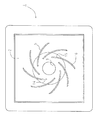
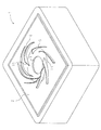
ガスこんろとしてのテーブルこんろ1は、図1、図2、図3に示すようにトッププレートとしての熱透過板2(例えば、透明ガラス板)に排気孔3が開口され、排気孔と同軸上で熱透過板2の下方には、熱透過板2と所定間隔をあけて表面燃焼式の輻射バーナ4が配置される。尚、排気孔3の直径は、輻射バーナ4の燃焼面の上面には排気孔3がかからない程度に小さく形成される。
排気孔3の周りの熱透過板2の上面には、調理容器Pを載置するための複数の五徳爪5(本発明の突起に相当する)が立設される。
As shown in FIGS. 1, 2, and 3, the
A plurality of five virtue claws 5 (corresponding to the protrusions of the present invention) for placing the cooking container P are erected on the upper surface of the heat
この輻射バーナ4は、燃焼に必要な空気の殆どを一次空気として吸入する全一次空気式のバーナであり、燃料ガスと一次空気とが供給されるバーナ本体6と、バーナ本体6に載置される燃焼面としてのバーナプレート7とを備える。輻射バーナ4は、その頭部がリング状であり、頭部の中央に中央開口部8が形成される。また、中央開口部8の下方には、汁受皿9が設けられる。
バーナプレート7は、リング状に形成された多孔質セラミックスの平面プレートで多数の貫通孔を有し、その燃焼面を水平方向に配置して、火炎を上方向に向けて燃焼するように設けられる。
バーナ本体6は、燃料ガスと一次空気とが供給されて混合される混合管10と、バーナプレート7の載置部となるリング状の混合気室11とからなる。混合管10の基端には、燃料ガスを噴出するノズル12が設けられ、ノズル12の周りには、ノズル12からの燃料ガスの噴出に伴い燃焼用一次空気を吸引するための一次空気口13が設けられる。
The
The burner plate 7 is a porous ceramic flat plate formed in a ring shape, and has a large number of through holes. The burner plate 7 is disposed in a horizontal direction so that the flame is burned upward. .
The
五徳爪5上に調理容器Pを載置すると、調理容器Pの底面と熱透過板2の上面との間にリング状の燃焼ガスの通過流路が形成され、燃焼ガスは外側へ導かれる。
また、熱透過板2の排気孔3のまわりは、排気孔3の中心から外側に向かって上向きに傾斜して傾斜部14を形成する。
そして、熱透過板2の上面と調理容器Pの底面とによって上下面を囲んだリング状の燃焼ガス通路においては、その通路断面積Aが、排気孔3の距離が遠くなるほど狭くなるように傾斜部14の角度が設定される。
When the cooking container P is placed on the five
Further, the periphery of the
And in the ring-shaped combustion gas passage which surrounded the upper and lower surfaces by the upper surface of the heat-transmitting
つまり、通路断面積Aは、排気孔3中心(輻射バーナ4中心)からの距離をr、熱透過板2から調理容器P底面までの高さをhとすると、
A=2πrh
として表わされ、rが大きい場所ほど、この通路断面積Aが小さくなるようにhが設定、つまり傾斜部14の角度が設定されている。
That is, the passage cross-sectional area A is defined as r from the center of the exhaust hole 3 (center of the radiant burner 4) and h as the height from the
A = 2πrh
H is set, that is, the angle of the
五徳爪5は、それぞれ排気孔3の中心(輻射バーナ4の中心)から放射状に向けた直線に対して排気孔3周方向に所定角度傾斜して外側に延びる円弧状の板状縦壁を、その内側先端から外側先端にかけて熱透過板2上面から立設して形成される。
従って、この五徳爪5を熱透過板2上面に所定間隔(排気孔3中心に所定角度ピッチ)で配置することにより、上方から見て、五徳爪5が熱透過板2上面に渦巻き状に形成される。
また、五徳爪5は、熱透過板2と一体加工により形成される。尚、五徳爪5は、熱透過板2と一体加工しなくてもよく、別体であっても構わない。
この五徳爪5は、その内周側の爪傾斜部15と、外周側の調理容器載置部16とからなる。
爪傾斜部15は、上端面が内側端から外方向に向かって高くなるように傾斜が設けられる。
調理容器載置部16は、その上端面が略水平に形成され、調理容器Pが載置される部分となる。
各五徳爪5は、同一形状をしているため、それぞれの調理容器載置部16の上端は同一水平面上に位置することとなり、調理容器Pの底面と円弧状に延びた曲線上で直接当接して、その左右空間を区分する。
こうして、リング状の燃焼ガス通路は、五徳爪5により、渦巻き状に細かく区画されて複数の燃焼ガス通路に分割される。
The five
Therefore, by arranging the five
Further, the five
The five
The claw inclined
The cooking
Since each of the five
Thus, the ring-shaped combustion gas passage is divided into a plurality of combustion gas passages in a spiral manner by the five
上述したテーブルこんろ1によれば、輻射バーナ4が燃焼を開始すると、バーナプレート7表面から輻射熱が放射される。この輻射熱は、熱透過板2を透過して調理容器Pの底面を間接的に加熱する。さらに、輻射バーナ4からの燃焼ガスは、熱透過板2に設けられた排気孔3を通って上昇し、調理容器Pの底面と熱透過板2の上面との間の燃焼ガス通路を通過する間に、その排気熱で調理容器Pを直接加熱する。この結果、輻射式ガスこんろ本来の輻射熱による間接加熱が燃焼ガスによる直接加熱によって補助されて、熱効率が向上する。
そして、リング状の燃焼ガス通路をしきって、複数の細かい燃焼ガス通路に分割しているため、燃焼ガスを狭い空間に均一に分配して流すことが可能となり、伝熱効率を向上させて高い熱効率を得ることができる。
さらに、分割した燃焼ガス通路を渦巻き状に区画しているため、燃焼ガスは、この燃焼ガス通路内を、五徳爪5の側面と衝突しながら通過する。五徳爪5と衝突した際に、燃焼ガスは水平方向から上方向に流れを変化させ、調理容器P底面への衝突を繰り返しながら外側に送られていく。
このため、区画された燃焼ガス通路内では、燃焼ガスが乱流して調理容器P底面には伝熱境界膜は形成されなくなり、燃焼ガスの熱が調理容器P底面に良好に伝わる。
さらに、燃焼ガスと調理容器P底面との接触距離を長くとることもできる。
これらの結果、高熱効率が達成される。
According to the
Since the ring-shaped combustion gas passage is completely divided into a plurality of fine combustion gas passages, the combustion gas can be evenly distributed and flown in a narrow space, improving heat transfer efficiency and high thermal efficiency. Can be obtained.
Further, since the divided combustion gas passages are partitioned in a spiral shape, the combustion gas passes through the combustion gas passages while colliding with the side surfaces of the five
For this reason, in the divided combustion gas passage, the combustion gas turbulently flows and the heat transfer boundary film is not formed on the bottom surface of the cooking vessel P, and the heat of the combustion gas is well transmitted to the bottom surface of the cooking vessel P.
Further, the contact distance between the combustion gas and the bottom surface of the cooking container P can be increased.
As a result, high thermal efficiency is achieved.
また、調理容器Pの大きさが五徳爪5のリング径よりも小さい場合には、燃焼ガスは調理容器Pよりも外周部に達すると、渦巻き状の五徳爪5に衝突して、そのまま上方向に送られ、調理容器P側面に沿って流れるため、調理容器P底面に加えて調理容器P側面においても良好に燃焼ガスとの熱交換が行われる。
In addition, when the size of the cooking container P is smaller than the ring diameter of the
さらに、五徳爪5が円弧状に外側に延び、熱透過板2面全体としては渦巻き状に形成されているため、燃焼ガスは五徳爪5側壁に衝突しながらスムーズに外側へ送られると共に、調理容器P底面との接触距離が長くても排気抵抗が少なく、熱分布も偏りが少なくなる。
Furthermore, since the
さらに、排気孔3のまわりの熱透過板2に傾斜部14を形成して、排気孔3(輻射バーナ4)からの距離が遠くなるほど燃焼ガス通路の通路面積を狭くする構成としたために、排気孔3から遠い箇所においては、燃焼ガス通路の通路面積を狭くして、燃焼ガスの流速を速くすることができる。このため、調理容器Pと燃焼ガスとの間の伝熱効率を向上させることができる。
さらに、燃焼ガスの体積流量は、輻射バーナ4からの距離が遠くなるほど、燃焼ガスの温度低下に伴い減少する。そのため、燃焼ガス通路の面積が輻射バーナ4からの距離が遠くなっても変化しなかった場合には、燃焼ガスは減速して拡散してしまい、熱効率は低下するが、本実施例では、輻射バーナ4からの距離が遠くなるほど燃焼ガス通路の通路面積を狭くしたために、燃焼ガスの体積流量減少に伴う燃焼ガスの流速低下を招かない。
したがって、高温の燃焼熱は燃焼ガス通路内で拡散することがなく、調理容器Pに燃焼熱を効率良く伝達することができる。
Further, since the
Further, the volumetric flow rate of the combustion gas decreases as the temperature of the combustion gas decreases as the distance from the
Therefore, the high-temperature combustion heat does not diffuse in the combustion gas passage, and the combustion heat can be efficiently transmitted to the cooking vessel P.
以上本発明の実施例について説明したが、本発明はこうした実施例に何等限定されるものではなく、本発明の要旨を逸脱しない範囲において、種々なる態様で実施し得ることは勿論である。
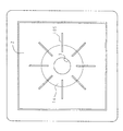
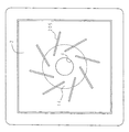
例えば、本実施例では円弧状の板で五徳爪5を形成したが、図4に示すように、直線板状の五徳爪105を排気孔3の中心から放射状に向けたものでもよく、更に、図5に示すように、直線板状の五徳爪205を中心から周方向に所定角度傾斜させて設けてもよい。
また、本実施例では、リング状の燃焼ガス通路を複数の円弧状の五徳爪5によって複数のガス通路に分割しているが、中心から外周方向へ向かった一連の渦巻き状の五徳爪で一続きの渦巻き状のガス通路を形成するようにしてもよい。
また、本実施例では、リング状の燃焼ガス通路の断面積を排気孔3の中心からの距離が遠くなるほど狭くなるようにしたが、距離が遠くなっても同等(通路断面積が変化しない)にしてもよい。また、熱透過板2の傾斜部14の傾斜角度を小さく、すなわち熱透過板2の下り傾斜を小さくすると、排気孔3からの距離が遠くなるにつれて通路断面積が広くなってしまうこともあるが、この場合でも、従来の平坦な熱透過板を備えた輻射式のガスこんろに比べれば、燃焼ガスの流速が遅くなる程度を抑制でき、熱効率を向上させることができる。
また、輻射バーナ4として、給気ファンを用いない自然燃焼式のバーナでの例を示したが、給気ファンを用いた強制燃焼式のバーナであっても構わない。
Although the embodiments of the present invention have been described above, the present invention is not limited to these embodiments, and it is needless to say that the present invention can be implemented in various modes without departing from the gist of the present invention.
For example, in the present embodiment, the
Further, in this embodiment, the ring-shaped combustion gas passage is divided into a plurality of gas passages by a plurality of arc-shaped five
Further, in this embodiment, the cross-sectional area of the ring-shaped combustion gas passage is made narrower as the distance from the center of the
Moreover, although the example by the natural combustion type burner which does not use an air supply fan was shown as the
本発明は、テーブルこんろおよびキッチンユニットに組込まれるビルトインこんろ等の各種のガスこんろに適用可能である。 The present invention can be applied to various gas stoves such as a built-in stove incorporated in a table stove and a kitchen unit.
1 テーブルこんろ
2 熱透過板
3 排気孔
4 輻射バーナ
5、105、205 五徳爪
14 傾斜部
DESCRIPTION OF
Claims (4)
上記突起は、上記燃焼ガス通路をしきって、複数の燃焼ガス通路に分割して燃焼ガスを外側に導くことを特徴とするガスこんろ。 The upper part of the radiant burner that radiates radiant heat is covered with a heat-transmitting plate, an exhaust hole for passage of combustion gas is opened in the heat-transmitting plate, and a cooking container is mounted around the exhaust hole on the upper surface of the heat-transmitting plate. In a gas stove that is provided with a projection for placement and forms a combustion gas passage extending around the exhaust hole between the upper surface of the heat-transmitting plate and the bottom surface of the cooking vessel,
A gas stove characterized in that the projection completely divides the combustion gas passage and is divided into a plurality of combustion gas passages to guide the combustion gas to the outside.
Priority Applications (1)
| Application Number | Priority Date | Filing Date | Title |
|---|---|---|---|
| JP2004110613A JP2005291663A (en) | 2004-04-05 | 2004-04-05 | Gas cookstove |
Applications Claiming Priority (1)
| Application Number | Priority Date | Filing Date | Title |
|---|---|---|---|
| JP2004110613A JP2005291663A (en) | 2004-04-05 | 2004-04-05 | Gas cookstove |
Publications (1)
| Publication Number | Publication Date |
|---|---|
| JP2005291663A true JP2005291663A (en) | 2005-10-20 |
Family
ID=35324781
Family Applications (1)
| Application Number | Title | Priority Date | Filing Date |
|---|---|---|---|
| JP2004110613A Pending JP2005291663A (en) | 2004-04-05 | 2004-04-05 | Gas cookstove |
Country Status (1)
| Country | Link |
|---|---|
| JP (1) | JP2005291663A (en) |
-
2004
- 2004-04-05 JP JP2004110613A patent/JP2005291663A/en active Pending
Similar Documents
| Publication | Publication Date | Title |
|---|---|---|
| US7721727B2 (en) | Cooking stove | |
| WO2022156046A1 (en) | Burner cap, burner and gas stove | |
| CN109000228B (en) | Burner | |
| US20080149093A1 (en) | Heating cooking appliance and burner system thereof | |
| CN106949466B (en) | burner and gas cooker | |
| JP5164594B2 (en) | Cooker | |
| JP4669997B2 (en) | Five virtues and gas stove with the five virtues | |
| CN101641554B (en) | heating cooking utensils | |
| CN207196491U (en) | Burner and gas kitchen ranges | |
| JP2005291663A (en) | Gas cookstove | |
| JP2006010298A (en) | Gas cooking stove | |
| CN110887076A (en) | Energy-gathering cover for stove and gas stove applying same | |
| JP2006010298A5 (en) | ||
| CN114543124A (en) | Hidden suspension burner assembly of stove | |
| JP4375789B2 (en) | Gas stove | |
| JP2005274024A (en) | Gas range | |
| JP2005172278A (en) | Range burner | |
| CN1995816B (en) | Gas radiation burner | |
| CN217356885U (en) | Combustor and gas stove comprising same | |
| CN217274120U (en) | Burner and gas cooker | |
| JP4470062B2 (en) | Gas stove | |
| JP2005291691A (en) | Gas cooking stove | |
| JP4595532B2 (en) | Gas stove | |
| JP5107083B2 (en) | Cooker | |
| JP4947742B2 (en) | Gas stove |
Legal Events
| Date | Code | Title | Description |
|---|---|---|---|
| A621 | Written request for application examination |
Free format text: JAPANESE INTERMEDIATE CODE: A621 Effective date: 20070326 |
|
| A977 | Report on retrieval |
Free format text: JAPANESE INTERMEDIATE CODE: A971007 Effective date: 20080825 |
|
| A131 | Notification of reasons for refusal |
Free format text: JAPANESE INTERMEDIATE CODE: A131 Effective date: 20080902 |
|
| A521 | Written amendment |
Free format text: JAPANESE INTERMEDIATE CODE: A523 Effective date: 20081101 |
|
| A02 | Decision of refusal |
Free format text: JAPANESE INTERMEDIATE CODE: A02 Effective date: 20090414 |