JP2005291691A - Gas cooking stove - Google Patents
Gas cooking stove Download PDFInfo
- Publication number
- JP2005291691A JP2005291691A JP2004330649A JP2004330649A JP2005291691A JP 2005291691 A JP2005291691 A JP 2005291691A JP 2004330649 A JP2004330649 A JP 2004330649A JP 2004330649 A JP2004330649 A JP 2004330649A JP 2005291691 A JP2005291691 A JP 2005291691A
- Authority
- JP
- Japan
- Prior art keywords
- combustion gas
- burner
- cooking container
- combustion
- ring
- Prior art date
- Legal status (The legal status is an assumption and is not a legal conclusion. Google has not performed a legal analysis and makes no representation as to the accuracy of the status listed.)
- Pending
Links
- 238000010411 cooking Methods 0.000 title claims abstract description 247
- 239000000567 combustion gas Substances 0.000 claims abstract description 262
- 210000000078 claw Anatomy 0.000 claims abstract description 128
- 230000002093 peripheral effect Effects 0.000 claims abstract description 77
- 239000007789 gas Substances 0.000 claims description 51
- 238000010438 heat treatment Methods 0.000 claims description 8
- 230000017525 heat dissipation Effects 0.000 claims description 6
- 238000003892 spreading Methods 0.000 claims description 2
- 230000007480 spreading Effects 0.000 claims description 2
- 238000001816 cooling Methods 0.000 abstract description 5
- 238000002485 combustion reaction Methods 0.000 description 93
- 239000000919 ceramic Substances 0.000 description 19
- 230000000694 effects Effects 0.000 description 19
- 239000002737 fuel gas Substances 0.000 description 12
- 230000007423 decrease Effects 0.000 description 10
- 230000009467 reduction Effects 0.000 description 8
- 230000008859 change Effects 0.000 description 7
- 230000006866 deterioration Effects 0.000 description 7
- 235000014347 soups Nutrition 0.000 description 7
- 210000002268 wool Anatomy 0.000 description 7
- 235000011389 fruit/vegetable juice Nutrition 0.000 description 6
- 230000005855 radiation Effects 0.000 description 6
- 239000011810 insulating material Substances 0.000 description 5
- 238000005192 partition Methods 0.000 description 5
- 230000015572 biosynthetic process Effects 0.000 description 4
- 238000011144 upstream manufacturing Methods 0.000 description 4
- 238000010586 diagram Methods 0.000 description 3
- 230000001771 impaired effect Effects 0.000 description 3
- 230000006872 improvement Effects 0.000 description 3
- 238000004519 manufacturing process Methods 0.000 description 3
- 238000003466 welding Methods 0.000 description 3
- UGFAIRIUMAVXCW-UHFFFAOYSA-N Carbon monoxide Chemical compound [O+]#[C-] UGFAIRIUMAVXCW-UHFFFAOYSA-N 0.000 description 2
- 229910002091 carbon monoxide Inorganic materials 0.000 description 2
- 238000009792 diffusion process Methods 0.000 description 2
- 238000009826 distribution Methods 0.000 description 2
- 238000002474 experimental method Methods 0.000 description 2
- 238000009413 insulation Methods 0.000 description 2
- 239000000463 material Substances 0.000 description 2
- 238000005219 brazing Methods 0.000 description 1
- 238000009841 combustion method Methods 0.000 description 1
- 238000005520 cutting process Methods 0.000 description 1
- 230000003247 decreasing effect Effects 0.000 description 1
- 238000005516 engineering process Methods 0.000 description 1
- 238000002347 injection Methods 0.000 description 1
- 239000007924 injection Substances 0.000 description 1
- 238000005304 joining Methods 0.000 description 1
- 230000013011 mating Effects 0.000 description 1
- 238000000034 method Methods 0.000 description 1
- 239000000203 mixture Substances 0.000 description 1
- 238000007789 sealing Methods 0.000 description 1
- 230000035939 shock Effects 0.000 description 1
Images


Classifications
-
- Y—GENERAL TAGGING OF NEW TECHNOLOGICAL DEVELOPMENTS; GENERAL TAGGING OF CROSS-SECTIONAL TECHNOLOGIES SPANNING OVER SEVERAL SECTIONS OF THE IPC; TECHNICAL SUBJECTS COVERED BY FORMER USPC CROSS-REFERENCE ART COLLECTIONS [XRACs] AND DIGESTS
- Y02—TECHNOLOGIES OR APPLICATIONS FOR MITIGATION OR ADAPTATION AGAINST CLIMATE CHANGE
- Y02B—CLIMATE CHANGE MITIGATION TECHNOLOGIES RELATED TO BUILDINGS, e.g. HOUSING, HOUSE APPLIANCES OR RELATED END-USER APPLICATIONS
- Y02B40/00—Technologies aiming at improving the efficiency of home appliances, e.g. induction cooking or efficient technologies for refrigerators, freezers or dish washers
Landscapes
- Gas Burners (AREA)
Abstract
Description
本発明は、調理容器を五徳上に載置してバーナで加熱調理するガスコンロに関する。 The present invention relates to a gas stove in which a cooking container is placed on Gotoku and cooked with a burner.
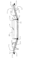
従来から、ガスコンロの分野においては、例えば図44,45に示すテーブルコンロ1のように、トッププレート12に設けられる開口の中央位置に、自然燃焼式ブンゼンバーナであるバーナ14が配置され、その周囲に汁受皿18が載置されるものが知られている。調理容器Pは、バーナ14の上方周囲に設けられた五徳20に載置され、バーナ14の燃焼により加熱される。15はバーナ本体、16はバーナヘッドである。
Conventionally, in the field of a gas stove, a
五徳20は、調理容器Pを載置する複数のL字状の五徳爪22と各五徳爪22の基盤となる五徳リング21とにより一体的に構成され、トッププレート12上に載置される。
五徳リング21の内周側には、リング中心に向かって下向きに傾斜した傾斜鍔部(以下、単に鍔部と呼ぶ)21cが延設される。
この五徳リング21とトッププレート12との間、及び五徳リング21と汁受皿18との間には、二次空気供給用の隙間が形成される。
The five
On the inner peripheral side of the virtually
A gap for supplying secondary air is formed between the five
また、最近では、特許文献1に示すように、調理容器Pの加熱効率を向上させるため、五徳爪22を低くしてバーナ14と調理容器Pとの間隔を小さくしたガスコンロが実用化されている。
このガスコンロは、図46に示すように、五徳20の鍔部21cをバーナヘッド16の主炎口16a近傍まで延ばした構成により、二次空気を火炎の基部から先端にまで供給する。
そして、バーナ14の燃焼ガスを、調理容器Pと五徳リング21との間の隙間(リング状燃焼ガス通路)から外部に放出する構成としている。23は、トッププレート12に嵌め込まれて五徳リング21を支持する突起部である。
この構造により、燃焼性能を良好に維持したまま、五徳爪22の高さを低くして調理容器Pをバーナヘッド16に接近させるとともに、五徳リング21によってバーナ14の燃焼ガスの拡散を防いで、高温の燃焼ガスと調理容器Pとを確実に接触させて、調理容器Pの加熱効率を上げることができる。
Recently, as shown in
As shown in FIG. 46, this gas stove supplies secondary air from the base of the flame to the tip by extending the
And it is set as the structure which discharge | releases the combustion gas of the
With this structure, while maintaining the combustion performance satisfactorily, the height of the five
一方、こうしたガスコンロにおいては、熱効率の向上技術に関して五徳の構成に特徴を有するものもある。
例えば、特許文献2に示すものでは、五徳リング上面に渦巻き状の仕切壁を形成し、その仕切壁の中間位置に上方へ突出した突起を設けて鍋載置部とした五徳が提案されている。
また、特許文献3に示すものでは、外炎式バーナの火炎噴出方向をバーナの中心と炎口とを結ぶ直線に対してバーナ周方向に所定角度傾けると共に、五徳爪の形成方向も同様に傾けることによって火炎と調理容器との接触距離を長くしようとしたガスコンロが提案されている。
On the other hand, some of these gas stoves have a characteristic of the five virtues regarding the technology for improving the thermal efficiency.
For example, in what is shown in
Moreover, in what is shown in
しかしながら、特許文献1のようなガスコンロでは、調理容器Pをバーナヘッド16に接近させることは考えられていても、五徳リング上面と調理容器P底面との間に形成されるリング状の燃焼ガス通路における燃焼ガスの流し方によって熱効率を更に向上させることは考えられてなく、改善の余地を残していた。
一般に、バーナで発生した燃焼ガス(火炎も含む)は、リング状燃焼ガス通路を通過して外側に排出されるが、その通過過程で温度低下して体積流量が減少する。また、リング状燃焼ガス通路は、外側にいくほど通路断面積が増大しているため、リング状燃焼ガス通路内では、その外側ほど燃焼ガスの通過速度が遅くなり熱流が拡散してしまう。
一方、燃焼ガスと調理容器との間の伝熱効率は、燃焼ガスを狭いリング状燃焼ガス通路に通過させたほうが良好となる。
この結果、従来のガスコンロでは、リング状燃焼ガス通路における外側ほど熱流が拡散してしまい充分な熱交換ができていなかった。
However, in the gas stove as in
In general, the combustion gas (including flame) generated in the burner passes through the ring-like combustion gas passage and is discharged to the outside. Further, since the cross-sectional area of the ring-shaped combustion gas passage increases toward the outer side, the passage speed of the combustion gas becomes slower toward the outer side in the ring-shaped combustion gas passage, and the heat flow is diffused.
On the other hand, the heat transfer efficiency between the combustion gas and the cooking vessel is better when the combustion gas is passed through a narrow ring-like combustion gas passage.
As a result, in the conventional gas stove, the heat flow is diffused toward the outer side in the ring-shaped combustion gas passage, and sufficient heat exchange cannot be performed.
そして、特許文献2の五徳では、仕切壁に設けた突起に調理容器を載置するため、調理容器底面と五徳リングとの間の燃焼ガス通路は、分割されていなく上部で連通していることになる。よって、渦巻き状の仕切壁で燃焼熱を蓄熱するに過ぎず、調理容器底面部においては、バーナの燃焼ガス(火炎も含む)は旋回せずにそのまま水平方向に流れてしまう。
また、特許文献3のコンロでは、燃焼ガスの噴出方向を傾け、それと同じ方向に五徳爪の形成方向も傾けるものであるため、燃焼ガスが放射方向に対して斜めに流れるだけで、調理容器との接触が充分に得られない。
つまり、これらの何れのコンロにおいても、燃焼ガスが層流状態のまま調理容器の下方を外側に流れることになる。
この場合、調理容器底面には薄い空気層による伝熱境界膜が形成されてしまい、この伝熱境界膜が断熱層として働き、燃焼ガスの調理容器への伝熱が妨げられていた。
この結果、高い熱効率が得られなかった。
And in Gotoku of
Moreover, in the stove of
That is, in any of these stoves, the combustion gas flows outwardly below the cooking vessel in a laminar flow state.
In this case, a heat transfer boundary film is formed by a thin air layer on the bottom surface of the cooking container, and this heat transfer boundary film functions as a heat insulating layer, preventing heat transfer of the combustion gas to the cooking container.
As a result, high thermal efficiency could not be obtained.
そこで本発明は、上記課題を解決し、五徳の構造やバーナの種類に起因したエネルギーロスをなくし、燃焼ガスと調理容器底面との熱交換による高い熱効率を得ることを目的とする。 Therefore, the present invention has an object to solve the above-described problems, eliminate energy loss due to the structure of the five virtues and the type of burner, and obtain high thermal efficiency by heat exchange between the combustion gas and the bottom surface of the cooking vessel.
上記課題を解決する本発明の請求項1記載のガスコンロは、五徳リング等のリング板の上面で横方向に拡がる燃焼ガスを、上方に向きを変えて調理容器の底面に衝突させる排気ガイド手段を設けたことを特徴とするものである。
請求項2に記載の発明は、請求項1記載のガスコンロにおいて、排気ガイド手段は、バーナの中心から放射状に向けた直線に対してバーナの周方向に傾斜してリング板の外側へ延びるガイド壁を備え、そのガイド壁面に沿ってバーナの燃焼ガスを外周方向に送りながら上方向に偏向させることで、ガイド壁が調理容器底面の下方に位置する部位では燃焼ガスを調理容器の底面に衝突させ、ガイド壁が調理容器底面の下方周囲に位置する部位では燃焼ガスを調理容器の側面に沿って上方に流す構成としたものである。
請求項3に記載の発明は、請求項2記載のガスコンロにおいて、ガイド壁を、上方から見て渦巻き状にリング板から立設させ、バーナの燃焼ガスを渦巻き旋回状に外周方向へ送りながら上方向に偏向させる構成としたものである。
The gas stove according to
According to a second aspect of the present invention, in the gas stove according to the first aspect, the exhaust guide means is a guide wall that is inclined in the circumferential direction of the burner with respect to a straight line radially extending from the center of the burner and extends to the outside of the ring plate. The burner combustion gas collides with the bottom surface of the cooking vessel at the portion where the guide wall is located below the bottom surface of the cooking vessel by deflecting the combustion gas of the burner along the guide wall surface in the outer circumferential direction. In the portion where the guide wall is located at the lower periphery of the bottom surface of the cooking vessel, the combustion gas is made to flow upward along the side surface of the cooking vessel.
According to a third aspect of the present invention, in the gas stove according to the second aspect, the guide wall is erected from the ring plate in a spiral shape when viewed from above, and the combustion gas of the burner is fed upward while being spirally swirled. It is configured to deflect in the direction.
請求項4に記載の発明は、請求項2又は3に記載のガスコンロにおいて、ガイド壁は、調理容器を支持する五徳爪を兼用する構成としたものである。
請求項5に記載の発明は、請求項3又は4に記載のガスコンロにおいて、ガイド壁は、リング板上に立設され、調理容器を載置した際に、その上端が調理容器底面へ渦巻きライン状に当接して、燃焼ガスの通過流路を、リング板上面とガイド壁と調理容器底面とにより囲まれる渦巻き状に区画形成する構成としたものである。
請求項6に記載の発明は、請求項1乃至5の何れかに記載のガスコンロにおいて、リング板の下面からの放熱を抑制する放熱抑制手段を備えたものである。
請求項7に記載の発明は、請求項1乃至6の何れかに記載のガスコンロにおいて、燃焼ガスの通過流路は、リング板の中心からの距離が遠くなる程狭くなる、或いは該距離が遠くなっても同等となるようにしたものである。
According to a fourth aspect of the present invention, in the gas stove according to the second or third aspect, the guide wall is configured to also serve as a virtuosity claw that supports the cooking container.
According to a fifth aspect of the present invention, in the gas stove according to the third or fourth aspect, the guide wall is erected on the ring plate, and when the cooking container is placed, the upper end of the guide wall is a spiral line to the bottom surface of the cooking container. The combustion gas passage is partitioned into a spiral shape surrounded by the upper surface of the ring plate, the guide wall, and the bottom surface of the cooking vessel.
A sixth aspect of the present invention is the gas stove according to any one of the first to fifth aspects, further comprising a heat dissipation suppressing means for suppressing heat dissipation from the lower surface of the ring plate.
According to a seventh aspect of the present invention, in the gas stove according to any one of the first to sixth aspects, the passage through which the combustion gas passes becomes narrower as the distance from the center of the ring plate increases, or the distance increases. Even so, it is the same.
請求項1に記載の発明によれば、排気ガイド手段によって燃焼ガスを上向きにして調理容器の底面に衝突させることで、燃焼ガスと調理容器底面との伝熱効率を向上させて、高い熱効率を得ることができる。また、火炎が調理容器側面よりも外周側に溢れることを抑制して、調理者の安全性を向上させることもできる。
請求項2に記載の発明によれば、燃焼ガスは、ガイド壁に沿って外周方向へ移動する際に、ガイド壁と衝突して上方向に流れを変化させ、調理容器底面に衝突する。
そのため、調理容器底面と燃焼ガスとの間の伝熱効率をより向上させることができる。
また、燃焼ガスは、調理容器よりも外周部に達すると、ガイド壁に衝突してそのまま上方向に送られ、調理容器側面に沿って上方に流れる。
そのため、調理容器底面に加えて調理容器側面においても良好に燃焼ガスとの熱交換が行われて、熱効率は一層向上する。
請求項3に記載の発明によれば、渦巻き状のガイド壁により、燃焼ガスはガイド壁に衝突しながらスムーズに外側へ送られると共に、リング板全体としては渦巻き状に流れるため、調理容器底面との接触距離を長くできる。よって、より効果的な熱効率の向上が期待できる。
According to the first aspect of the present invention, the heat transfer efficiency between the combustion gas and the bottom surface of the cooking vessel is improved by causing the combustion gas to face upward and collide with the bottom surface of the cooking vessel by the exhaust guide means, thereby obtaining high thermal efficiency. be able to. Moreover, it can suppress that a flame overflows to an outer peripheral side rather than a cooking container side surface, and can also improve a chef's safety | security.
According to the second aspect of the present invention, when the combustion gas moves in the outer peripheral direction along the guide wall, the combustion gas collides with the guide wall to change the flow upward, and collides with the bottom surface of the cooking container.
Therefore, the heat transfer efficiency between a cooking vessel bottom face and combustion gas can be improved more.
Moreover, when combustion gas reaches an outer peripheral part rather than a cooking vessel, it will collide with a guide wall and will be sent upwards as it is, and will flow upwards along a cooking vessel side surface.
Therefore, heat exchange with the combustion gas is favorably performed on the side surface of the cooking container in addition to the bottom surface of the cooking container, and the thermal efficiency is further improved.
According to the third aspect of the present invention, the combustion gas is smoothly sent to the outside while colliding with the guide wall by the spiral guide wall, and the entire ring plate flows spirally. The contact distance can be increased. Therefore, more effective improvement in thermal efficiency can be expected.
請求項4に記載の発明によれば、仕切壁を調理容器を載置支持する五徳爪に兼用することで、わざわざ特別に排気ガイド手段を設ける必要がなくなり、製造コストを低減できる。
請求項5に記載の発明によれば、調調理容器を載置した時に、ガイド壁の上端が調理容器と渦巻ライン状に当接して、燃焼ガス通路を、リング板上面とガイド壁と調理容器底面とにより囲まれる渦巻き状に区画形成された複数の燃焼ガス通路に分割する。
このため、バーナの燃焼ガスは、渦巻き状に夫々区画形成された燃焼ガス通路に流入し、そこで、ガイド壁と衝突しながら通過する。そして、燃焼ガスはガイド壁と衝突した際に、水平方向から上方向に流れを変化させ、調理容器底面に衝突する。そのため、調理容器底面と燃焼ガスとの間の伝熱効率を向上させることができる。
According to the fourth aspect of the present invention, it is not necessary to specially provide the exhaust guide means by combining the partition wall with the five virtue claws for placing and supporting the cooking container, and the manufacturing cost can be reduced.
According to the fifth aspect of the present invention, when the cooking container is placed, the upper end of the guide wall comes into contact with the cooking container in a spiral line shape, and the combustion gas passage is formed between the upper surface of the ring plate, the guide wall, and the cooking container. The gas is divided into a plurality of combustion gas passages formed in a spiral shape surrounded by the bottom surface.
For this reason, the combustion gas of the burner flows into the combustion gas passages each formed in a spiral shape, and passes there while colliding with the guide wall. And when a combustion gas collides with a guide wall, a flow is changed from a horizontal direction to an upward direction, and collides with a cooking vessel bottom face. Therefore, the heat transfer efficiency between a cooking vessel bottom face and combustion gas can be improved.
請求項6に記載の発明によれば、放熱抑制手段が、リング板の下面からの放熱を抑制する。そのため、調理容器とリング板との間を通過する燃焼ガスの、リング板下面からの放熱が抑制され、燃焼ガスの温度低下を防止することができる。
従って、バーナの燃焼ガス熱を調理容器の加熱に有効に用いることができ、熱効率を向上させることができる。
また、リング板からの放熱による調理環境の悪化を抑制することができる。
請求項7に記載の発明によれば、バーナからの距離が遠くなるほど燃焼ガス通路の通過流路を狭く、或いは遠くなっても同等としたことで、バーナからの距離が近い、つまり燃焼空間に近い箇所においては、燃焼ガス通路をバーナの燃焼性を損なわせない程度に広く保持することができるとともに、バーナから遠い箇所においては、燃焼ガス通路の通路断面積を狭く、或いは同等として、燃焼ガスと調理容器との間の伝熱効率を向上させることができる。
また、燃焼ガスの体積流量は、バーナからの距離が遠くなるほど、燃焼ガスの温度低下に伴い減少する。そのため、従来のガスコンロのように、燃焼ガス通路の断面積がバーナからの距離が遠くなるほど広くなるものでは、一層、燃焼ガスが減速して拡散してしまい、熱効率が低下する。
しかし、この発明ではバーナからの距離が遠くなるほど燃焼ガス通路の通路断面積が広くならないようにしたために、燃焼ガスの体積流量減少に伴う燃焼ガスの流速低下を招かない。したがって、燃焼ガスの拡散による熱効率の低下を引き起こすことがない。
According to the invention described in claim 6, the heat dissipation suppressing means suppresses heat dissipation from the lower surface of the ring plate. Therefore, the heat release from the lower surface of the ring plate of the combustion gas passing between the cooking vessel and the ring plate is suppressed, and the temperature reduction of the combustion gas can be prevented.
Therefore, the combustion gas heat of the burner can be effectively used for heating the cooking container, and the thermal efficiency can be improved.
Moreover, deterioration of the cooking environment due to heat radiation from the ring plate can be suppressed.
According to the seventh aspect of the present invention, the distance from the burner is short, that is, in the combustion space, by making the passage of the combustion gas passage narrower as the distance from the burner becomes longer or the same even if the distance from the burner becomes longer. In the vicinity, the combustion gas passage can be kept as wide as possible without impairing the burnability of the burner, and in the location far from the burner, the combustion gas passage has a narrow or equivalent passage cross-sectional area. Heat transfer efficiency between the cooking container and the cooking container can be improved.
Further, the volumetric flow rate of the combustion gas decreases with a decrease in the temperature of the combustion gas as the distance from the burner increases. Therefore, when the cross-sectional area of the combustion gas passage becomes wider as the distance from the burner increases as in the conventional gas stove, the combustion gas is further decelerated and diffused, and the thermal efficiency is lowered.
However, in the present invention, the passage cross-sectional area of the combustion gas passage is not increased as the distance from the burner is increased, so that the flow velocity of the combustion gas is not reduced due to the reduction in the volume flow rate of the combustion gas. Therefore, the thermal efficiency is not lowered due to the diffusion of the combustion gas.
以上説明した本発明の構成、作用を一層明らかにするために、以下、本発明のガスコンロにおける好的な実施例について説明する。
尚、従来例と重複する点については同一符号を付して説明を省略する。
In order to further clarify the configuration and operation of the present invention described above, a preferred embodiment of the gas stove according to the present invention will be described below.
In addition, about the point which overlaps with a prior art example, the same code | symbol is attached | subjected and description is abbreviate | omitted.
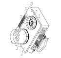
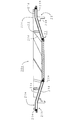
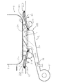
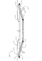
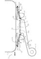
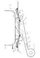
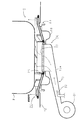
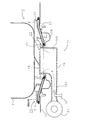
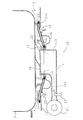
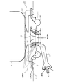
ガスコンロとしてのテーブルコンロは、図3、図4に示すようにトッププレート12に開口が設けられ、その開口の中央位置にバーナ14が配置され、開口外周縁に汁受皿18が載置される。調理容器Pは、汁受皿18の上方に設けられる五徳20に載置される。
As shown in FIGS. 3 and 4, the table stove as a gas stove has an opening in the
バーナ14は、中央に開口部が形成されて環状混合気室を有するバーナ本体15と、バーナ本体15に載置することにより外周縁に多数の主炎口を形成するバーナヘッド16とからなる。
The
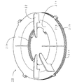
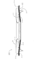
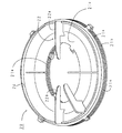
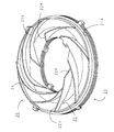
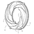
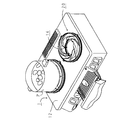
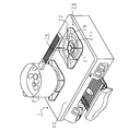
五徳20は、図1、図2に示すように、調理容器Pを載置する複数の五徳爪22と、トッププレート12の開口と汁受皿18との重ね部上部を覆うと共に五徳爪22を立設する基盤となる五徳リング21と、五徳20本体をトッププレート12上に固定するための突起部23とにより一体的に構成される。
As shown in FIGS. 1 and 2, the
五徳リング21はリング板状であり、二次空気を下方からバーナ炎口付近に案内するとともに、調理容器P底面との間に通過流路を形成して、燃焼ガスを外側へ導く。
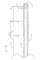
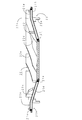
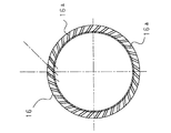
五徳リング21は、調理容器Pと対面する表板21aと、汁受皿18およびトッププレート12と対面する裏板21bとから形成される2重構造である。
この表板21a、裏板21bは、それぞれ外周側において表板水平面部21g、裏板水平面部21hを有するとともに、内周側において、リング中心に向かって下向きに傾斜した表側傾斜鍔部21c、裏側傾斜鍔部21d(以下、表側鍔部21c、裏側鍔部21dと呼ぶ)が延設される。
鍔部21c、21dの先端は、バーナ14炎口の外周面と接近させ、しかも、鍔部21c、21dの傾斜角度は、バーナ14の主炎口16aにおけるガスの噴出角度とほぼ平行に形成する。
また、この表板21aと裏板21bとは、外周端部全周と内周端部全周とにおいて、それぞれ断熱材としてのセラミック21eを挟着して、外周端部および内周端部それぞれ4箇所においてかしめ固定される。
The
The
The
The tips of the
Further, the
五徳爪22は、L字形状であり、固定部22aと調理容器載置部22bとからなる。
固定部22aは、下端において表板21aに溶接固定され、調理容器載置部22bは、固定部22a上部から五徳リング21中心に向かって略水平に延びている。
また、突起部23は、2段形状であり、上端において裏板21bに溶接固定されると共に、最下端の小突起23aのみがトッププレート12の孔にはめ込まれる。この突起部23の段差により、裏板21bとトッププレート12との間に二次空気供給用の隙間が形成される。
The
The fixing part 22a is welded and fixed to the
The
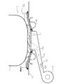
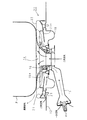
このテーブルコンロ1は、五徳リング21における鍔部21c、21dの先端を主炎口16aに接近して延設したために、バーナ14の燃焼時においては、図4に示すように、燃焼用二次空気が裏板21bとトッププレート12との間から裏側鍔部21dと汁受皿18との間を通って主炎口16a近傍に導かれる。この結果、二次空気が火炎の基部から先端まで全体にわたって供給されて、燃焼性能が向上する。つまり、五徳爪22を低くして調理容器Pの載置面をバーナ14に近づけて調理容器Pへの加熱効率の向上を図っても、燃焼性能を良好に維持することができる構造のものである。
また、主炎口16aに形成された火炎の燃焼ガスは、五徳リング21の表板21aと調理容器Pの間の隙間を通って外部に排出される。ここで、五徳爪22を低くして表板21aと調理容器Pとの間隔を狭く形成しているために、高温の燃焼ガスは、調理容器Pになめるようにして通過する。従って、調理容器Pはバーナ14燃焼ガスと効率よく接触して加熱される。
なお、二次空気の供給は、五徳リング21の裏板21bとトッププレート12との間に形成した隙間から行う構造のものに限らずに、例えば、汁受皿18に二次空気供給用の孔を形成して行う構造のものについても適用でき、この場合も同様の効果が得られる。
Since this
Moreover, the combustion gas of the flame formed in the main flame opening 16a is discharged outside through the gap between the
The supply of the secondary air is not limited to a structure in which the secondary air is supplied from a gap formed between the
さらに、このような五徳リング21と調理容器Pとを対面させて燃焼ガス通路を形成する五徳20において、五徳リング21を高温の燃焼ガスと直接接触する表板21aと、バーナ燃焼ガスとは直接接触しない裏板21bとによる2重構造としたために、表板21aと裏板21bとの間に形成された隙間が断熱層として働き、表板21aに伝熱したバーナ14燃焼ガスの熱は裏面から放熱しない。
また、五徳リング21の内周端部および外周端部全周にわたって、表板21aと裏板21bとの間にセラミック21eを挟着し、表板21aと裏板21bとの連結部(かしめ固定部)を内周端部、外周端部それぞれ4箇所としたために、表板21aに伝熱した燃焼ガス熱が、内周及び外周端部より裏板21bへ伝熱することを抑制することができる。従って、表板21aに伝熱したバーナ燃焼ガス熱の裏板21bへの伝熱を確実に抑制することができる。
なお、この連結部の面積は、小さいほど断熱効果が得られる。例えば、表板21aおよび裏板21bをそれぞれセラミック21eに接着して、表板21aと裏板21bとの連結面積を0とした場合には、いっそうの効果が得られる。
このような構造により、バーナ14燃焼ガスの温度低下を防止することができ、バーナ14の燃焼ガス熱を調理容器Pの加熱に有効に用いることができる。
これにより、熱効率を向上させることができるとともに、五徳20からの放熱による調理環境の悪化を抑制することができる。
Furthermore, in the five
Further, the ceramic 21e is sandwiched between the
In addition, the heat insulation effect is acquired, so that the area of this connection part is small. For example, when the
With such a structure, the temperature reduction of the
Thereby, while being able to improve thermal efficiency, the deterioration of the cooking environment by the heat radiation from
次に実施例2のテーブルコンロについて図5を用いて説明する。
尚、実施例1と異なる部分について説明し、重複する部分に関しては同一符号を付してその説明を省略する。
Next, a table stove according to the second embodiment will be described with reference to FIG.
In addition, a different part from Example 1 is demonstrated, about the overlapping part, the same code | symbol is attached | subjected and the description is abbreviate | omitted.
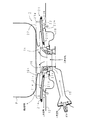
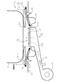
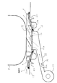
実施例2のテーブルコンロ1bは、燃焼用空気を強制的に供給して燃焼を行う強制燃焼式バーナの上方周囲に、実施例1で説明した2重構造の五徳20を設けたものである。
The table stove 1b of the second embodiment is provided with the double-structured
このバーナ14aは、燃焼に必要な空気の殆どを一次空気として吸入する全一次空気式のバーナであり、燃焼面としてのバーナプレート17と、バーナ本体15とを備える。
バーナプレート17は、多孔質セラミックスの平面プレートで多数の貫通孔を有している。
バーナ本体15は、上流端において、燃焼用空気を供給するための給気ファン31が接続されて、空気供給通路の途中に、燃料ガスを噴出するガスノズル32が設けられる。また、ガスノズル32の下流には、燃料ガスと燃焼用空気とを混合させるための混合管15aが形成される。
なお、五徳20の裏板21bとトッププレート12との間には、実施例1のテーブルコンロ1において形成された2次空気供給用の隙間は形成されない。
The burner 14a is an all-primary air type burner that sucks most of air necessary for combustion as primary air, and includes a
The
An
In addition, between the
バーナ14a燃焼時には、バーナ本体15に、ガスノズル32から燃料ガスが供給されるとともに、給気ファン31により一次空気が強制的に供給される。
そして、バーナプレート17上で燃焼後、燃焼ガスは表板21aと調理容器Pの間の隙間を通って外部に排出される。
During combustion of the burner 14 a, fuel gas is supplied from the
And after combustion on the
このように、燃焼用空気を強制的に供給することにより、同じ燃焼量の場合でも、燃焼用空間を狭くして熱効率を向上させることができる。
つまり、燃焼用空気が自然ドラフト力に供給される場合には、燃焼用空間を狭くしてしまうとドラフト力が形成されず、燃焼空気の給気・排気がスムーズに行われないため、燃焼状態が悪化してしまうが、本実施例では燃焼用空気が空気ファン13により強制的に供給されるために、燃焼用空間を狭くしても良好な燃焼状態を得ることができる。
このように、バーナ14aと調理容器Pとの距離を狭くすることができるために、いっそう熱効率を向上させることができる。
また、燃焼用空気供給用の隙間を設ける必要がないために、燃焼熱が二次空気供給用の隙間から逃げ出すことがない。
さらに、このようにバーナ燃焼ガス通路を五徳リング21で形成した場合には、五徳リング21が高温となり、五徳リング21からの外部への放熱量が多くなってしまうが、五徳リング21を表板21aと裏板21bとによる2重構造としたために、燃焼ガスの五徳からの外部への放熱を抑制することができる。つまり、燃焼ガス熱の高温となるガスコンロにおいて、二重構造とした五徳は断熱効果をいっそう奏する。
As described above, by forcibly supplying the combustion air, it is possible to narrow the combustion space and improve the thermal efficiency even when the combustion amount is the same.
In other words, when combustion air is supplied to natural draft force, if the combustion space is narrowed, draft force is not formed, and combustion air is not supplied or exhausted smoothly. However, in this embodiment, since the combustion air is forcibly supplied by the air fan 13, a good combustion state can be obtained even if the combustion space is narrowed.
As described above, since the distance between the burner 14a and the cooking container P can be reduced, the thermal efficiency can be further improved.
In addition, since it is not necessary to provide a gap for supplying combustion air, combustion heat does not escape from the gap for supplying secondary air.
In addition, when the burner combustion gas passage is formed by the
次に実施例3のテーブルコンロについて説明する。
尚、実施例2と異なる部分について説明し、重複する部分に関しては同一符号を付してその説明を省略する。
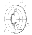
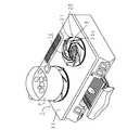
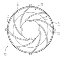
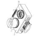
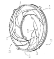
実施例3のテーブルコンロは、調理容器を載置する五徳爪の形状について、図9〜図12に示すように上方から見て渦巻き形状としたものである。
Next, a table stove according to the third embodiment will be described.
In addition, a different part from Example 2 is demonstrated, about the overlapping part, the same code | symbol is attached | subjected and the description is abbreviate | omitted.
The table stove of Example 3 is a spiral shape as seen from above, as shown in FIGS.
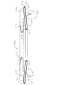
この五徳20aは、五徳リング21と五徳爪22と突起部23とからなり、五徳リング21と突起部23とは、実施例1、2と同様の形状である。
The five
五徳爪22は、調理容器載置部22cと傾斜部22dとを備え、図10に示すように、上方から見て、五徳リング21内周側から外周側に向かって渦巻き状に形成される。この五徳爪22は、下端部全面において表板21aと溶接固定される。
傾斜部22dは、五徳爪22における内周側に形成されて、上端面が中心方向から外周方向に向かって高くなるように傾斜が設けられる。
五徳爪22dの外周側には、調理容器載置部22cが位置する。調理容器載置部22cの上端面は水平に形成される。
この調理容器載置部22cの上端面に、図12に示すように、調理容器Pが載置されて、調理容器載置部22cと調理容器P底面と表板21aとで囲まれる複数の区画された燃焼ガス通路を形成するように構成される。
The
The
A cooking
As shown in FIG. 12, the cooking container P is placed on the upper end surface of the cooking
このテーブルコンロ1aでは、五徳爪22を渦巻き形状としたために、バーナ14の燃焼ガス流は、五徳爪22に沿って渦状に形成される。
そのため、燃焼ガスが外部に排出される前に、その熱を調理容器Pに有効に伝熱させることができる。
またこの場合、燃焼ガスから五徳リング21への伝熱効率も向上するために、表板21aの温度についても上昇してしまうが、五徳リング21を2重構造としたために、五徳リング21の裏面から燃焼ガス熱が放熱してしまうことがない。そのため、熱効率の向上効果をいっそう得ることができる。
In this table stove 1a, since the
Therefore, the heat can be effectively transferred to the cooking container P before the combustion gas is discharged to the outside.
Further, in this case, the heat transfer efficiency from the combustion gas to the virtually
さらに、五徳爪22における内周側に傾斜部22dを設けて、五徳爪22がバーナ火炎の形成される領域内に入らないようにしたために、五徳爪22が火炎にあぶられることがない。そのため、火炎が低温の五徳爪22と接触することによる燃焼性の悪化や、熱効率の低下を招くことがない。
Furthermore, since the
次に実施例4のテーブルコンロについて説明する。
尚、実施例1と異なる部分について説明し、重複する部分に関しては同一符号を付してその説明を省略する。
実施例4のテーブルコンロは、図6に示すように、表板21aと裏板21bとの間の空間に、断熱材としてのセラミックウール21fを隙間なく挟着した構造としたものである。
Next, a table stove according to the fourth embodiment will be described.
In addition, a different part from Example 1 is demonstrated, about the overlapping part, the same code | symbol is attached | subjected and the description is abbreviate | omitted.
As shown in FIG. 6, the table stove of Example 4 has a structure in which ceramic wool 21f as a heat insulating material is sandwiched between the
このような構造により、表板21aに伝熱したバーナ燃焼ガス熱は、セラミックウール21fによって断熱される。
したがって、バーナ燃焼ガス熱の外部への放出を確実に抑制し、熱効率を向上させることができるとともに、調理環境の悪化を抑制することができる。
また、表板21aと裏板21bとの間にセラミックウール21fを詰めて空洞を形成しない構成としたために、五徳リング21の機械的強度を向上させることができる。
さらに、断熱材としてセラミックウール21fを用いたために、セラミックウール21fは緩衝材としても働き、五徳20上に加わった衝撃や振動を吸収する。このため、五徳20をうっかり落としてしまった場合など、五徳20上に衝撃が加わった場合であっても強度を保持することができるとともに、振動による騒音を抑制することができる。
With such a structure, the burner combustion gas heat transferred to the
Therefore, release of burner combustion gas heat to the outside can be reliably suppressed, thermal efficiency can be improved, and deterioration of the cooking environment can be suppressed.
Further, since the ceramic wool 21f is packed between the
Further, since the ceramic wool 21f is used as a heat insulating material, the ceramic wool 21f also functions as a buffer material and absorbs shocks and vibrations applied to the
次に実施例5のテーブルコンロについて説明する。
尚、実施例1と異なる部分について説明し、重複する部分に関しては同一符号を付してその説明を省略する。
実施例5のテーブルコンロは、五徳について、表板と裏板との間の空間を真空状態としたものである。
Next, a table stove according to the fifth embodiment will be described.
In addition, a different part from Example 1 is demonstrated, about the overlapping part, the same code | symbol is attached | subjected and the description is abbreviate | omitted.
In the table stove of Example 5, the space between the front plate and the back plate is in a vacuum state for the five virtues.
この五徳について、図7、図8を用いて説明する。
この五徳20cは、五徳リング21と五徳爪22と突起部23とからなり、五徳爪22と突起部23とは、実施例1と同様の形状である。
The five virtues will be described with reference to FIGS.
The five
五徳リング21は、調理容器Pと対面する表板21aと、汁受皿18およびトッププレート12と対面する裏板21bとによる2重構造である。
この表板21a、裏板21bは、それぞれ外周側において水平面部21g、21hを有するとともに、内周側において鍔部21c、21dが延設される。
そして、内周端全周と外周端全周とにおいて、それぞれ内側に折曲した絞り部21i、21jおよび内周方向および外周方向に突出した溶接代21k、21lが、表板21aと裏板21bとのそれぞれに形成される。
また、裏板21bの下面には、表板21aと裏板21bとの間を真空状態とするための吸引口Hが形成される。
The
Each of the
And in the inner periphery end whole periphery and the outer periphery end whole periphery, the narrow part 21i, 21j and
In addition, a suction port H for forming a vacuum state between the
この表板21aと裏板21bとは、溶接代21k、21lにおいて溶接接合される。
そして、吸引口Hより吸引排気をした後、吸引口Hを蓋体Sにより閉塞して、蓋体Sを裏板21bにろう接接合する。このろう接接合は、表板21aと裏板21bとの間の真空度を所定範囲に保ちながら、接合するために採用されるものである。
The
Then, after suctioning and exhausting from the suction port H, the suction port H is closed by the lid S, and the lid S is brazed to the
このように、表板21aと裏板21bとの間を真空状態としたために、真空部が断熱層として作用する。
真空状態においては、表板21aと裏板21bとの間に分子が存在しないために、分子間の熱移動が起こらない。
したがって、バーナ燃焼ガス熱の外部への放出を一層確実に抑制し、熱効率を向上させることができるとともに、調理環境の悪化を抑制することができる。
Thus, since the space between the
In a vacuum state, since no molecules exist between the
Accordingly, the release of burner combustion gas heat to the outside can be more reliably suppressed, the thermal efficiency can be improved, and the deterioration of the cooking environment can be suppressed.
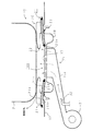
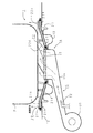
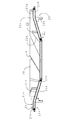
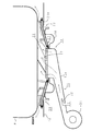
ガスコンロとしてのテーブルコンロは、図13、図14に示すようにトッププレート12に開口が設けられ、その開口の中央位置にバーナ14が配置される。バーナ14の上方周囲には、調理容器Pを載置するための五徳20が設けられる。
As shown in FIGS. 13 and 14, the table stove as a gas stove is provided with an opening in the
このバーナ14は、燃焼に必要な空気の殆どを一次空気として吸入する全一次空気式のバーナであり、燃焼面としてのバーナプレート17と、バーナ本体15とを備える。
バーナプレート17は、多孔質セラミックスの平面プレートで多数の貫通孔を有し、その燃焼面を水平方向に配置して、火炎を上方向に向けて燃焼するように設けられる。
バーナ本体15は、上流端において、燃焼用空気を供給するための給気ファン31が接続されて、空気供給通路の途中に、燃料ガスを噴出するガスノズル32が設けられる。また、ガスノズル32の下流には、燃料ガスと燃焼用空気とを混合させるための混合管15aが形成される。
The
The
An
五徳20は、実施例3で説明した図9〜11のものと同じ構造で、五徳爪22は、上方から見て、五徳リング21内周側から外周側に向かって渦巻き状に形成され、下端部全面において表板21aと溶接固定されるもので、その内周側の傾斜部22dと、外周側の調理容器載置部22cとからなる。
傾斜部22dは、上端面が内側端から外方向に向かって高くなるように傾斜が設けられる。図15に示すように、この傾斜部22dの最上端部Aとバーナ14中心との距離aは、バーナ14半径bの1.5倍である。
調理容器載置部22cは、その上端面が水平に形成され、図14に示すように、調理容器Pが載置される。こうして、五徳リング21上には調理容器載置部22cと調理容器P底面と表板21aとで囲まれる複数の区画された燃焼ガス通路を形成するように構成される。
The
The
The upper end surface of the cooking
バーナ14燃焼時には、バーナ本体15に、ガスノズル32から燃料ガスが供給されるとともに、給気ファン31により一次空気が強制的に供給される。
そして、バーナプレート17上で上向きに形成された燃焼炎は、調理容器P底面に衝突すると、調理容器P底面に沿って、放射状に外方向に向けて形成される。
During combustion of the
When the combustion flame formed upward on the
このように燃焼用空気を強制的に供給するため、燃焼用空気を自然ドラフト力により供給する自然燃焼式ガスコンロと比較して、燃焼空間を狭くしても良好な燃焼状態を得ることができる。また、燃焼用空気を強制的に供給することにより、五徳爪22を渦巻き状とし、燃焼ガス通路に抵抗を設けた場合でも、良好な燃焼を維持することができる。
従って、バーナ14と調理容器P底面との距離を短くして、燃焼炎と調理容器P底面との伝熱効率を向上させることができるとともに、燃焼ガスの流れを制御して、燃焼ガスと調理容器Pとの伝熱効率を向上させることができる。
また、火炎を上向きに形成することにより、調理容器P底面と火炎との接触面積を増加させて、熱効率を向上させることができる。
Since the combustion air is forcibly supplied in this way, a good combustion state can be obtained even if the combustion space is narrowed compared to a natural combustion gas stove that supplies the combustion air by natural draft force. Further, by forcibly supplying the combustion air, good combustion can be maintained even when the
Accordingly, the distance between the
Moreover, by forming the flame upward, the contact area between the bottom surface of the cooking container P and the flame can be increased, and the thermal efficiency can be improved.
また、五徳爪22を渦巻き形状としたために、燃焼ガスは、調理容器P底面と五徳リング21と五徳爪22との間の隙間によって区画形成される燃焼ガス通路を、常に五徳爪22と衝突しながら通過する。この五徳爪22と衝突した際に、燃焼ガスは水平方向から上方向に流れを変化させ、調理容器底面Pに衝突する。
そのため、調理容器P底面と燃焼ガスとの間の伝熱効率を向上させることができる。
また、燃焼ガスは、調理容器Pよりも外周部に達すると、渦巻き状の五徳爪22に衝突して、そのまま上方向に送られ、調理容器P側面に沿って流れる。
この結果、調理容器P底面に加えて調理容器P側面においても良好に燃焼ガスとの熱交換が行われて、熱効率はいっそう向上する。
Further, since the
Therefore, the heat transfer efficiency between the bottom surface of the cooking container P and the combustion gas can be improved.
Moreover, when combustion gas reaches an outer peripheral part rather than the cooking container P, it collides with the
As a result, heat exchange with the combustion gas is favorably performed on the side surface of the cooking container P in addition to the bottom surface of the cooking container P, and the thermal efficiency is further improved.
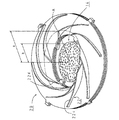
また、図15に示すように、五徳爪22における調理容器載置部内側に傾斜部22dを設けて、傾斜部22dの最上端部Aとバーナ14中心との距離aを、バーナ14半径bの1.5倍としたために、五徳爪22はバーナ火炎の形成される領域内に入らない。
燃焼用空気を強制的に供給して、調理容器Pとバーナプレート17との距離を限界まで近づけた場合には、燃焼炎が形成される領域は、バーナ14半径の約1.5倍となることが、発明者らの実験によって確認されている。そのため、傾斜部22dの最上端部Aとバーナ14中心との距離aを、バーナ14半径bの1.5倍未満とした場合には、五徳爪22は燃焼炎によってあぶられてしまう。
本実施例では、傾斜部22dの最上端部Aとバーナ14中心との距離aを、バーナ14半径bの1.5倍としたために、五徳爪22はバーナ火炎によってあぶられることがない。
従って、火炎が五徳爪22によって冷却され、燃焼性が悪化してしまい、一酸化炭素ガスを発生させてしまうということがない。また、燃焼炎の熱エネルギーが五徳爪22に奪われることがないため、熱効率の低下を引き起こさない。さらに、燃焼炎によって五徳爪22が加熱されてしまい、五徳20の耐久性が失われるということがない。
Further, as shown in FIG. 15, an
When the combustion air is forcibly supplied and the distance between the cooking vessel P and the
In this embodiment, since the distance a between the uppermost end A of the
Accordingly, the flame is not cooled by the five
ここで、バーナ14火炎は、炎口から調理容器P底面に向かって上方向に形成された後、調理容器P底面の中心部から外方向に放射状に形成されるため、五徳爪22において燃焼炎と接触するのは、調理容器Pを載置する上部のみである。
また、五徳爪22内側端とバーナ14との距離を離しすぎてしまった場合には、燃焼ガス流れの渦巻き状に形成される領域が小さくなってしまう。特に、径の小さい調理容器Pを載置した場合には、燃焼ガスは、流れが完全に渦巻き状に形成される前に外部に放出されてしまうために、上述した燃焼ガス流れを渦巻き状に形成することによる伝熱効率の向上効果があまり得られない。
そこで、本実施例では、五徳爪22における内側端に傾斜部22dを設けて、五徳爪22上方において五徳爪22がバーナ14火炎の形成される領域内に入らないようにするとともに、五徳爪22下方においてはバーナ14に近づけて、早い段階で燃焼ガスの流れを渦巻き状に形成する整流効果を保持する構成とした。
これにより、いっそう熱効率が向上する。
Here, after the
In addition, if the distance between the inner end of the five
Therefore, in this embodiment, an
Thereby, thermal efficiency improves further.
さらに、調理容器Pと対面して燃焼ガス通路を形成する五徳リング21において、高温の燃焼ガスと直接接触する表板21aと、バーナ燃焼ガスとは直接接触しない裏板21bとによる2重構造としたために、表板21aと裏板21bとの間に形成された隙間が断熱層として働き、表板21aに伝熱したバーナ14燃焼ガスの熱は裏面から放熱しない。
また、五徳リング21の内周端部および外周端部全周にわたって、表板21aと裏板21bとの間にセラミック21eを挟着し、表板21aと裏板21bとの連結部(かしめ固定部)を内周端部、外周端部それぞれ4箇所としたために、表板21aに伝熱した燃焼ガス熱が、内周及び外周端部より裏板21bへ伝熱することを抑制することができる。従って、表板21aに伝熱したバーナ燃焼ガス熱の裏板21bへの伝熱を確実に抑制することができる。
このような構造により、バーナ燃焼ガスの温度低下を防止することができ、バーナの燃焼ガス熱を調理容器の加熱に有効に用いることができる。
これにより、熱効率を向上させることができるとともに、五徳からの放熱による調理環境の悪化を抑制することができる。
Further, in the
Further, the ceramic 21e is sandwiched between the
With such a structure, the temperature of the burner combustion gas can be prevented from decreasing, and the combustion gas heat of the burner can be effectively used for heating the cooking vessel.
Thereby, while being able to improve thermal efficiency, the deterioration of the cooking environment by the heat radiation from five virtues can be suppressed.
なお、環状バーナの内側に向かって炎が形成される内炎口バーナ(例えば、特開平9−4853)を搭載したテーブルコンロにおいても、上述した効果は同様に得られる。 Note that the above-described effects can be similarly obtained in a table stove equipped with an internal flame burner (for example, JP-A-9-4853) in which a flame is formed toward the inside of the annular burner.
以下、この内炎口バーナについて簡単に説明をする。
内炎口バーナは、環状バーナであって、内周壁に多数の炎口を備える。そして、この炎口に形成される火炎は、中心方向に向かった後、五徳上の調理容器の中央部と接触し、外向きに放射状に形成される。
そのため、バーナ能力の大小にかかわらず、調理容器を均等に加熱することができるとともに、炎を外部に溢れさせない。
Hereinafter, the internal flame burner will be briefly described.
The internal flame burner is an annular burner and includes a large number of flame ports on the inner peripheral wall. And after the flame formed in this flame mouth goes to the center direction, it contacts the center part of the cooking container on Gotoku, and is formed radially outward.
Therefore, the cooking container can be heated evenly regardless of the burner capacity, and the flame does not overflow outside.
このような内炎口バーナでは、火炎は、中心方向に向かった後、五徳上の調理容器の中央部と接触し、外向きに形成されるために、燃焼炎端部のバーナ中心からの距離は、上述した上向き炎口バーナと比較して小さくなる。つまり、燃焼炎が形成される領域は、バーナ半径の1.5倍以下となり、五徳爪の調理容器を載置する載置部の内周側端部とバーナ中心との距離を、バーナ半径の1.5倍以上とする五徳の構造は、内向き炎口バーナを備えたガスコンロにおいても適用できる。また、炎口が完全な上向き、内向きでなくても、所定角度上向きに形成されていれば適用できる。 In such an internal flame burner, since the flame is directed toward the center, and then contacts the center of the cooking container on the virtues and is formed outward, the distance from the burner center at the end of the combustion flame Is smaller than the upward flame burner described above. That is, the area where the combustion flame is formed is 1.5 times or less of the burner radius, and the distance between the inner peripheral side end of the placing portion on which the cooking container for Gotoku nail is placed and the burner center is set to the burner radius. The structure of five virtues that is 1.5 times or more can also be applied to a gas stove equipped with an inward flame burner. Further, even if the flame opening is not completely upward or inward, it can be applied as long as it is formed at a predetermined angle upward.
ガスコンロとしてのテーブルコンロは、図18、図19に示すようにトッププレート12に開口が設けられ、その開口の中央位置に円筒状のバーナ14が配置される。バーナ14の上方周囲には、調理容器Pを載置するための五徳20が設けられる。
As shown in FIGS. 18 and 19, the table stove as a gas stove has an opening in the
このバーナ14は、燃焼に必要な空気の殆どを一次空気として吸入する全一次空気式のバーナであり、燃焼面としてのバーナプレート17と、バーナ本体15とを備える。
バーナプレート17は、多孔質セラミックスの平面プレートで多数の貫通孔を有し、その燃焼面を水平方向に配置して、火炎を上方向に向けて燃焼するように設けられる。
バーナ本体15は、上流端において、燃焼用空気を供給するための給気ファン31が接続されて、空気供給通路の途中に、燃料ガスを噴出するガスノズル32が設けられる。また、ガスノズル32の下流には、燃料ガスと燃焼用空気とを混合させるための混合管15aが形成される。
The
The
An
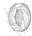
次に、五徳20の形状について、図16〜18を用いて説明する。
五徳20は、調理容器Pを載置支持する複数の五徳爪22と、バーナ14の周囲に設けられトッププレート12の開口と汁受皿18との重ね部上部を覆うと共に五徳爪22を立設する基盤となる五徳リング21(本発明のリング板に相当する)と、五徳リング21外周部上面に上向きに突出して設けられる環状の整流板24と、五徳20本体をトッププレート12上に固定するための突起部23とにより一体的に構成される。
Next, the shape of
The
五徳リング21はリング板状であり、五徳爪22上面に当接される調理容器P底面との間にリング状の燃焼ガスの通過流路を形成して外側へ導く。
五徳リング21は、調理容器Pと対面する表板21aと、汁受皿18およびトッププレート12と対面する裏板21bとから形成される2重構造である。
この表板21a、裏板21bは、それぞれ外周側において水平面部21g、21hを有するとともに、内周側において、リング中心に向かって下向きに傾斜した傾斜鍔部21c、21dが延設される。傾斜鍔部21c、21dの先端は、バーナ14の外周側面に近接して設けられ、五徳リング21とバーナ14との間には、隙間が殆ど形成されない。
従って、五徳リング21上面とバーナ14と調理容器P底面とによって上下面を殆ど隙間なく囲んで殆ど外気が流入しない燃焼ガス通路(バーナの燃焼領域も含む)が形成される。
The
The
The
Therefore, a combustion gas passage (including the burner combustion region) is formed by surrounding the upper and lower surfaces with almost no gap between the upper surface of the virtually
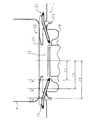
また、バーナ14周囲の五徳リング21上面と調理容器P底面とによって上下面を囲んだリング状の燃焼ガス通路においては、その通路断面積Aが、バーナ14からの距離が遠くなるほど狭くなるように傾斜鍔部21c,dの角度が設定されている。
つまり、バーナ中心(五徳リング中心)からの距離をr、五徳リングと調理容器底面との距離をhとすると、図20に示す(r1、h1)、(r2、h2)、(r3、h3)における断面積A1、A2、A3の関係は、
A1=2πr1h1>A2=2πr2h2>A3=2πr3h3
と示すことができる。
Further, in the ring-shaped combustion gas passage surrounded by the upper surface and the bottom surface of the
That is, if the distance from the burner center (center of the virtuosity ring) is r, and the distance between the virtuosity ring and the bottom of the cooking container is h, (r1, h1), (r2, h2), (r3, h3) shown in FIG. The relationship between the cross-sectional areas A1, A2, and A3 in
A1 = 2πr1h1> A2 = 2πr2h2> A3 = 2πr3h3
Can be shown.
また、五徳リング21の表板21aと裏板21bとは、外周端部全周と内周端部全周とにおいて、それぞれ断熱材としてのセラミック21eを挟着して、外周端部および内周端部それぞれ4箇所においてかしめ固定される。
Further, the
五徳爪22は、L字形の板体であり、固定部22aと調理容器載置部22bとからなる。
固定部22aは、下端において表板21aに溶接固定され、調理容器載置部22bは、固定部22a上部から五徳リング21中心に向かって略水平に延びている。
また、突起部23は、上端において裏板21bに溶接固定されると共に、下端においてトッププレート12の孔にはめ込まれる。
The
The fixing part 22a is welded and fixed to the
The
また、五徳リング21の表板21aには、上向きに突出した環状の整流板24が設けられる。
環状の整流板24は、五徳リング21と同軸上に形成され、その径は、五徳爪22の外周部と同径である。この整流板24は、厳密に五徳リング21の外周端に立設されていなくても、五徳リング21上面の外周端近傍に立設されていればよい。
また、整流板24の上端高さは、五徳爪22の調理容器載置部22bの上端高さよりも低い。
In addition, the
The
Moreover, the upper end height of the rectifying
バーナ14燃焼時には、バーナ本体15に、ガスノズル32から燃料ガスが供給されるとともに、給気ファン31により一次空気が強制的に供給される。
そして、バーナプレート17上で燃焼後、燃焼ガスは表板21aと調理容器Pの間の隙間を半径方向外側に向かって流れ、整流板24に衝突すると、上方向に流れをかえる。この上方向に流れた燃焼ガスは、調理容器P側面に沿って流れた後で、外部に放出される。
During combustion of the
Then, after combustion on the
このように、燃焼用空気を強制的に供給することにより、燃焼用空気が自然ドラフト力に供給される場合と比較して、燃焼用空間を狭くしても良好な燃焼状態を得ることができる。
そのため、バーナ14と調理容器P底面との距離を短くして、燃焼炎と調理容器P底面との接触面積を増加させ、伝熱効率を向上させることができる。
Thus, by forcibly supplying the combustion air, it is possible to obtain a good combustion state even if the combustion space is narrowed compared to the case where the combustion air is supplied to the natural draft force. .
Therefore, the distance between the
また、バーナ14の燃焼ガスを、バーナ14と五徳リング21と調理容器P底面とによって殆ど隙間なく囲んだ燃焼ガス通路を通過させ、その外周部から燃焼ガスを排出する構成としたために、燃焼ガス通路に外気が流入することがなく、燃焼熱の外気による冷却を抑制することができる。また、燃焼ガス通路を薄い円盤形状としたために、燃焼熱が無駄に燃焼ガス通路に拡散することがなく、高温の燃焼ガスは、調理容器P底面をなめるようにして通過した後で外部に排出される。
これにより、調理容器Pは燃焼ガスと効率よく接触して加熱される。
この効果は、特に、2次空気を供給するための隙間を不要とし、円盤状の燃焼ガス通路を薄く密閉できる強制燃焼式バーナを用いた場合に顕著に現れる。
Further, since the combustion gas of the
Thereby, the cooking container P is efficiently brought into contact with the combustion gas and heated.
This effect is particularly prominent when a forced combustion burner is used in which a gap for supplying secondary air is not required and the disk-like combustion gas passage can be thinly sealed.
さらに、五徳リング21に傾斜鍔部21cを設けて、バーナ14からの距離が遠くなるほど燃焼ガス通路の通路面積を狭くする構成としたために、バーナ14からの距離が近い、つまり燃焼空間に近い箇所においては、バーナ14の燃焼性を損なわせないとともに、バーナ14から遠い箇所においては、燃焼ガス通路の通路面積を狭くして、燃焼ガスの流速を速くすることができる。
そのため、バーナ14の燃焼性を良好に保ちつつ、調理容器Pと燃焼ガスとの間の伝熱効率を向上させることができる。
さらに、燃焼ガスの体積流量は、バーナ14からの距離が遠くなるほど、燃焼ガスの温度低下に伴い減少する。そのため、燃焼ガス通路の面積がバーナ14からの距離が遠くなっても変化しなかった場合には、燃焼ガスは減速して拡散してしまい、熱効率は低下する。一方、本実施例では、バーナ14からの距離が遠くなるほど燃焼ガス通路の通路面積を狭くしたために、燃焼ガスの体積流量減少に伴う燃焼ガスの流速低下を招かない。
したがって、高温の燃焼ガスは燃焼ガス通路内で拡散することなく、調理容器P底面をなめるようにして通過した後で外部に排出される。
これにより、調理容器Pは燃焼ガスと効率よく接触して加熱される。
Furthermore, since the
Therefore, the heat transfer efficiency between the cooking vessel P and the combustion gas can be improved while keeping the burnability of the
Furthermore, the volumetric flow rate of the combustion gas decreases with a decrease in the temperature of the combustion gas as the distance from the
Accordingly, the high-temperature combustion gas does not diffuse in the combustion gas passage and is discharged outside after passing through the bottom surface of the cooking vessel P.
Thereby, the cooking container P is efficiently brought into contact with the combustion gas and heated.
また、五徳リング21の表板21aに、環状の整流板24を上向きに形成したため、燃焼ガスは五徳リング21と調理容器Pの間の隙間を半径方向外側に向かって流れた後、整流板24に衝突し、上方向に流れをかえる。
すなわち、整流板24の径よりも小さい調理容器Pを載置した場合には、燃焼ガスは、調理容器P底面と五徳リング21との間を、調理容器P底面に沿って流れた後、五徳リング21外周端部の整流板24に衝突すると、調理容器側面に沿って流れる。
この結果、調理容器P底面に加えて調理容器P側面においても良好に燃焼ガスとの熱交換が行われて、熱効率は向上する。
また、整流板24の径よりも大きい調理容器Pを載置した場合には、図21に示すように、燃焼ガスは、整流板24に衝突し、上方向に流れを変化させた後、調理容器P底面に衝突する。そのため、調理容器P底面と燃焼ガスとの間の伝熱効率をいっそう向上させることができる。
Further, since the
That is, when the cooking container P smaller than the diameter of the rectifying
As a result, heat exchange with the combustion gas is favorably performed on the side surface of the cooking container P in addition to the bottom surface of the cooking container P, and the thermal efficiency is improved.
Moreover, when the cooking container P larger than the diameter of the rectifying
また、調理容器Pとを対面して燃焼ガス通路を形成する五徳リング21において、高温の燃焼ガスと直接接触する表板21aと、バーナ燃焼ガスとは直接接触しない裏板21bとによる2重構造としたために、表板と裏板との間に形成された隙間が断熱層として働き、表板21aに伝熱したバーナ14燃焼ガスの熱は裏面から放熱しない。
また、五徳リング21の内周端部および外周端部全周にわたって、表板21aと裏板21bとの間にセラミック21eを挟着し、表板21aと裏板21bとの連結部(かしめ固定部)を内周端部、外周端部それぞれ4箇所としたために、表板21aに伝熱した燃焼ガス熱が、内周及び外周端部より裏板21bへ伝熱することを抑制することができる。従って、表板21aに伝熱したバーナ燃焼ガス熱の裏板21bへの伝熱を確実に抑制することができる。
このような構造により、バーナ燃焼ガスの温度低下を防止することができ、バーナの燃焼ガス熱を調理容器Pの加熱に有効に用いることができる。
これにより、熱効率を向上させることができるとともに、五徳20からの放熱による調理環境の悪化を抑制することができる。
Further, in the
Further, the ceramic 21e is sandwiched between the
With such a structure, the temperature reduction of the burner combustion gas can be prevented, and the combustion gas heat of the burner can be effectively used for heating the cooking vessel P.
Thereby, while being able to improve thermal efficiency, the deterioration of the cooking environment by the heat radiation from
次に実施例8のテーブルコンロについて説明する。
尚、実施例7と異なる部分について説明し、重複する部分に関しては同一符号を付してその説明を省略する。
Next, a table stove according to the eighth embodiment will be described.
In addition, a different part from Example 7 is demonstrated, about the overlapping part, the same code | symbol is attached | subjected and the description is abbreviate | omitted.
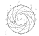
実施例8のテーブルコンロ1は、調理容器を載置する五徳爪の形状について、図22〜図26に示すように上方から見て渦巻き形状としたものである。
この五徳20は、五徳リング21と五徳爪22と突起部23と整流板24とからなり、五徳リング21と突起部23と整流板24とは、実施例1と同様の形状である。また、整流板24の上端高さは、後述する五徳爪22の外周端部の高さよりも低い。
The
The five
五徳爪22は、図22、図23に示すように、それぞれバーナ14の中心(五徳リング21の中心)から放射状に向けた直線に対してバーナ周方向に所定角度傾斜して外側に延びる円弧状の板状縦壁を、その内側先端から外側先端にかけて五徳リング21上面から立設して形成される。
従って、この五徳爪22を五徳リング21上面に所定間隔(リング中心に所定角度ピッチ)で配置することにより、上方から見て、五徳爪22が五徳リング21上面に渦巻き状に形成される。
この五徳爪22は、その内周側の傾斜部22dと、外周側の調理容器載置部22cとからなる。
傾斜部22dは、上端面が内側端から外方向に向かって高くなるように傾斜が設けられる。図27に示すように、この傾斜部22dの最上端部Aとバーナ14中心との距離aは、バーナ14半径bの1.5倍である。
調理容器載置部22cは、その上端面が略水平に形成され、図25に示すように、調理容器Pが載置される。
つまり、調理容器載置部22cは、調理容器Pの底面と渦巻き状に延びた曲線上で直接当接して、その左右空間を区分する。
また、第7実施例と同様に、五徳リング21の内側先端は、バーナ14の外周側面に近接して設けられる為、五徳リング21とバーナ14と間には隙間が殆ど形成されないため、五徳リング21上面とバーナ14と調理容器P底面とによって上下面を殆ど隙間なく囲んで殆ど外気が流入しない燃焼ガス通路が形成される。
更に、バーナ14の周囲の五徳リング21上面と調理容器P底面とによって上下面を囲んだリング状の燃焼ガス通路においても、第1実施例と同様に、その通路断面積Aが、バーナ14からの距離が遠くなるほど狭くなるように傾斜鍔部21c,dの角度が設定されている。
こうして、リング状の燃焼ガス通路は、五徳爪22により、渦巻き状に区画された複数の燃焼ガス通路に分割される。
なお、この調理容器載置部22cにおいては、図30に示すように、製造誤差等により調理容器P底面と当接する最頂端Cの高さhmax と外周端Dの高さhD が相違する場合であっても、その高さの差Δhは、外周端Dの高さhD よりも小さいものとする。つまり、Δh=(hmax −hD )≦hD の条件を満たすものとする。
As shown in FIGS. 22 and 23, the
Therefore, by arranging the five
The five
The
The cooking
That is, the cooking
Similarly to the seventh embodiment, since the inner tip of the virtually
Further, also in the ring-shaped combustion gas passage surrounded by the upper surface and the bottom surface of the
Thus, the ring-shaped combustion gas passage is divided into a plurality of combustion gas passages divided in a spiral shape by the five
In the cooking
調理中においては、バーナ14の燃焼により発生した燃焼ガスは、渦巻き状に区画された複数の燃焼ガス通路に流入し、五徳爪22と衝突しながら渦巻き状に通過する。そして、この五徳爪22と衝突した際に、燃焼ガスは水平方向から上方向に流れを変化させ、調理容器P底面に衝突する。
一般に、燃焼ガスが調理容器P底面を水平方向に流れた場合には、その流れが層流状態となって、調理容器P底面に空気層による伝熱境界膜が形成され、この伝熱境界膜が断熱層として働いてしまうが、本実施例では、燃焼ガスが五徳爪22の側壁に衝突して上方向に向きを変えるため、燃焼ガス通路に流れる燃焼ガスは乱流状態となるため、伝熱境界膜は形成されない。
このため、調理容器P底面と燃焼ガスとの間の伝熱効率を向上させることができる。
また、調理容器Pの大きさが五徳リング21の径よりも小さい場合には、燃焼ガスは調理容器Pよりも外周部に達すると、渦巻き状の五徳爪22に衝突して、そのまま上方向に送られ、調理容器P側面に沿って流れる。
この結果、調理容器P底面に加えて調理容器P側面においても良好に燃焼ガスとの熱交換が行われる。
また、渦巻き状に分割された燃焼ガス通路の通路断面積が、バーナ14から遠くなるほど狭くなるように形成されるため、燃焼ガスの拡散が防止される。
これらの結果、熱効率が極めて向上する。
During cooking, the combustion gas generated by the combustion of the
In general, when the combustion gas flows in the horizontal direction on the bottom surface of the cooking vessel P, the flow becomes a laminar flow state, and a heat transfer boundary film is formed by an air layer on the bottom surface of the cooking vessel P. However, in this embodiment, since the combustion gas collides with the side wall of the
For this reason, the heat transfer efficiency between the bottom face of the cooking vessel P and the combustion gas can be improved.
In addition, when the size of the cooking container P is smaller than the diameter of the virtually
As a result, heat exchange with the combustion gas is favorably performed on the side surface of the cooking container P in addition to the bottom surface of the cooking container P.
Further, since the passage cross-sectional area of the combustion gas passage divided in a spiral shape is formed so as to become farther from the
As a result, the thermal efficiency is greatly improved.
また、調理容器P底面と当接する五徳爪22最頂端Cの高さhmax と五徳爪22外周端Dの高さhD が相違する場合であっても、その高さの差Δhは、外周端Dの高さhD よりも小さいものとしたために、五徳爪上部と調理容器底面との間から燃焼ガスが拡散することを抑制することができる。
そのため、燃焼ガスは、調理容器P底面と五徳リング21と五徳爪22との間の隙間によって区画形成される燃焼ガス通路を確実に通過する。
これにより、燃焼ガスの理想的な渦巻き流れが形成され、燃焼ガスと調理容器Pとの間の伝熱効率を確実に向上させることができる。
Further, even when the height hmax of the topmost end C of the
For this reason, the combustion gas surely passes through the combustion gas passage formed by the gap between the bottom surface of the cooking container P, the five virtue rings 21 and the five
Thereby, an ideal spiral flow of the combustion gas is formed, and the heat transfer efficiency between the combustion gas and the cooking vessel P can be reliably improved.
また、図27に示すように、五徳爪22における調理容器載置部内側に傾斜部22dを設けて、傾斜部22dの最上端部Aとバーナ14中心との距離aを、バーナ14半径bの1.5倍としたために、五徳爪22はバーナ火炎の形成される領域内に入らない。
燃焼用空気を強制的に供給して、調理容器Pとバーナプレート17との距離を限界まで近づけた場合には、上方向の燃焼炎は、調理容器P底面に衝突して放射状に外方向に広がるが、その燃焼炎が形成される領域は、バーナ14半径の約1.5倍となることが発明者らの実験によって確認されている。
そのため、傾斜部22dの最上端部Aとバーナ14中心との距離aを、バーナ14半径bの1.5倍未満とした場合には、五徳爪22はその上部が燃焼炎によってあぶられてしまう。
本実施例では、五徳爪22の内側の上部を斜めにカットした傾斜部22dを形成し、その最上端部Aとバーナ14中心との距離aを、バーナ14半径bの1.5倍(1.5倍以上であればよい)としたために、五徳爪22はバーナ火炎によってあぶられることがない。
従って、火炎が五徳爪22によって冷却され、燃焼性が悪化してしまい、一酸化炭素ガスを発生させてしまうということがない。また、燃焼炎の熱エネルギーが五徳爪22に奪われることがないため、熱効率の低下を引き起こさない。さらに、燃焼炎によって五徳爪22が加熱されてしまい、五徳20の耐久性が失われるということがない。
In addition, as shown in FIG. 27, an
When the combustion air is forcibly supplied and the distance between the cooking vessel P and the
Therefore, when the distance a between the uppermost end A of the
In the present embodiment, an
Accordingly, the flame is not cooled by the five
また、五徳爪22内側端とバーナ14との距離を離しすぎてしまった場合には、燃焼ガス流れの渦巻き状に形成される領域が小さくなってしまう。特に、径の小さい調理容器Pを載置した場合には、燃焼ガスは、流れが完全に渦巻き状に形成される前に外部に放出されてしまうために、上述した燃焼ガス流れを渦巻き状に形成することによる伝熱効率の向上効果があまり得られない。
そこで、本実施例では、五徳爪22における内側端に傾斜部22dを設けて、五徳爪22上方において五徳爪22がバーナ14火炎の形成される領域内に入らないようにするとともに、五徳爪22下方においてはバーナ14に近づけて、早い段階で燃焼ガスの流れを渦巻き状に形成する整流効果を保持する構成とした。
これにより、いっそう熱効率が向上する。
In addition, if the distance between the inner end of the five
Therefore, in this embodiment, an
Thereby, thermal efficiency improves further.
また、整流板24により、燃焼ガスの流れは確実に上向きに変化する。
そのため、調理容器Pの径が整流板24よりも大きい場合には、図28に示すように、燃焼ガスは確実に調理容器P底面に衝突した後、整流板24上端面と調理容器P底面との間の隙間を通過して外部に放出される。従って、燃焼ガスと調理容器P底面との伝熱効率を向上させることができる。
また、調理容器Pの径が整流板24よりも小さい場合には、図25に示すように、燃焼ガスは、渦巻き状の五徳爪22により区画形成された燃焼ガス通路を通過中に上方に送られるものの、その一部は上方に送られずに整流板24まで達することがある。こうした場合でも、整流板24により燃焼ガスは、上方に案内される。
そのため、燃焼ガスと調理容器P側面との伝熱効率を向上させることができる。
しかも、この整流板24の上端面の高さは、五徳爪22の上端面の高さよりも低いために、燃焼ガスの排気出口を塞いでしまうことがない。
In addition, the flow of the combustion gas surely changes upward by the rectifying
Therefore, when the diameter of the cooking vessel P is larger than that of the rectifying
When the diameter of the cooking container P is smaller than that of the rectifying
Therefore, the heat transfer efficiency between the combustion gas and the side surface of the cooking container P can be improved.
In addition, since the height of the upper end surface of the
さらに、五徳爪22が円弧状に外側に延び、五徳リング21面全体としては渦巻き状に形成されているため、燃焼ガスは五徳爪22側壁に衝突しながらスムーズに外側へ送られると共に、調理容器P底面との接触距離が長くても排気抵抗が少なく、熱分布も偏りが少なくなる。
Furthermore, since the
また、バーナ14の燃焼ガスを、バーナ14と五徳リング21と調理容器P底面とによって殆ど隙間なく囲んだ燃焼ガス通路を通過させ、その外周部から燃焼ガスを排出する構成としたために、燃焼ガス通路に外気が流入することがなく、燃焼熱の外気による冷却を抑制することができる。
In addition, since the combustion gas of the
さらに、五徳リング21に傾斜鍔部21cを設けて、バーナ14からの距離が遠くなるほど燃焼ガス通路の通路面積を狭くする構成としたために、バーナ14からの距離が近い、つまり燃焼空間に近い箇所においては、バーナ14の燃焼性を損なわせないとともに、バーナ14から遠い箇所においては、燃焼ガス通路の通路面積を狭くして、燃焼ガスの流速を速くすることができる。
そのため、バーナ14の燃焼性を良好に保ちつつ、調理容器Pと燃焼ガスとの間の伝熱効率を向上させることができる。
さらに、燃焼ガスの体積流量は、バーナ14からの距離が遠くなるほど、燃焼ガスの温度低下に伴い減少する。そのため、燃焼ガス通路の面積がバーナ14からの距離が遠くなっても変化しなかった場合には、燃焼ガスは減速して拡散してしまい、熱効率は低下するが、本実施例では、バーナ14からの距離が遠くなるほど燃焼ガス通路の通路面積を狭くしたために、燃焼ガスの体積流量減少に伴う燃焼ガスの流速低下を招かない。
したがって、高温の燃焼熱は燃焼ガス通路内で拡散することがなく、調理容器Pに燃焼熱を効率良く伝達することができる。
Furthermore, since the
Therefore, the heat transfer efficiency between the cooking vessel P and the combustion gas can be improved while keeping the burnability of the
Furthermore, the volumetric flow rate of the combustion gas decreases with a decrease in the temperature of the combustion gas as the distance from the
Therefore, the high-temperature combustion heat does not diffuse in the combustion gas passage, and the combustion heat can be efficiently transmitted to the cooking vessel P.
次に実施例9のテーブルコンロについて図29を用いて説明する。
実施例9のテーブルコンロ1は、調理容器を載置する五徳爪の配置に関して特徴を有するもので、他の構成については、全て第8実施例と同一である。
この第9実施例の五徳20は、一般的な調理容器であれば、必ず燃焼ガスが五徳爪22に衝突して調理容器P底面に衝突するようにしたものである。
つまり、小鍋を用いた場合には、五徳爪2の配設間隔やその傾斜角度によっては、燃焼ガスが五徳爪22に衝突することなくそのまま外側へ排出されてしまう領域ができてしまうが、この実施例では、バーナ14の中心(五徳リング21の中心)と五徳爪22の調理容器載置部22cの内側先端Aとを結ぶ直線が、隣接する五徳爪22に対してバーナ中心Oから水平方向に70mm以内のところで交差(交点X)するように五徳爪を配設している。
Next, a table stove according to the ninth embodiment will be described with reference to FIG.
The
The
That is, when a small pan is used, an area where combustion gas is discharged to the outside without colliding with the five
一般に、調理容器は、直径160mm以上のものが使用される。そして、鍋の外周部の曲率半径を10mmとすると、バーナ中心から半径70mm以内の範囲は必ず鍋底載置面となる。
従って、燃焼ガスが五徳爪22に衝突することなくそのまま外側へ排出されてしまう領域ができないようにするためには、バーナ中心Oから水平面上での放射方向のどの角度においても、この半径70mmの領域内で調理容器載置部22cが存在すれば良いことになる。
そこで、本実施例では、バーナ中心Oと五徳爪22の調理容器載置部22cの内側先端Aとを結ぶ直線が、隣接する五徳爪22に対してバーナ中心Oから水平方向に70mm以内のところで交差するように五徳爪を配設するのである。
このため、小鍋を用いた場合であっても、全周にわたって燃焼ガスの五徳爪22への衝突を生じさせることができ、先の実施例で示した作用効果を確実に得ることができる。
Generally, a cooking container having a diameter of 160 mm or more is used. And if the curvature radius of the outer peripheral part of a pan shall be 10 mm, the range within the radius of 70 mm from the burner center will necessarily become a pan bottom mounting surface.
Therefore, in order to prevent a region in which the combustion gas is discharged as it is without colliding with the
Therefore, in this embodiment, the straight line connecting the burner center O and the inner tip A of the cooking
For this reason, even if it is a case where a small pan is used, the collision of combustion gas to the five
次に実施例10のテーブルコンロについて説明する。
尚、実施例8と異なる部分について説明し、重複する部分に関しては同一符号を付してその説明を省略する。
Next, a table stove according to the tenth embodiment will be described.
In addition, a different part from Example 8 is demonstrated, about the overlapping part, the same code | symbol is attached | subjected and the description is abbreviate | omitted.
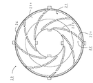
実施例10のテーブルコンロ1は、調理容器を載置する五徳爪の形状について、図31、図32に示すように上方から見て渦巻き形状とするとともに、断続的に形成したものである。
この五徳20は、五徳リング21と五徳爪22と突起部23と整流板24とからなり、五徳リング21と突起部23と整流板24とは、実施例2と同様の形状である。
渦巻き状に形成される五徳爪22は、それぞれ3つの分割片から構成される。
The
The five
The five
このように五徳爪22を非連続とした場合には、五徳爪22を連続とした場合と比較して、五徳爪22の体積が減少する。これにより、五徳爪22によって奪われる燃焼熱の割合を減少させることができる。
したがって、調理容器と五徳リングとの間を流れる燃焼熱の温度低下を防止して、調理容器への伝熱効率を向上させることができる。
また、五徳爪22を完全に非連続としなくても、例えば図39に示すように、調理容器載置部22cのみを切り欠いて非連続としても、効果が得られる。
In this way, when the
Therefore, the temperature reduction of the combustion heat which flows between a cooking vessel and a Gotoku ring can be prevented, and the heat transfer efficiency to a cooking vessel can be improved.
Further, even if the
次に実施例11のテーブルコンロについて説明する。
尚、実施例8と異なる部分について説明し、重複する部分に関しては同一符号を付してその説明を省略する。
Next, a table stove according to the eleventh embodiment will be described.
In addition, a different part from Example 8 is demonstrated, about the overlapping part, the same code | symbol is attached | subjected and the description is abbreviate | omitted.
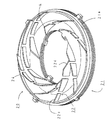
実施例11のテーブルコンロ1は、調理容器を載置する五徳爪の形状について、図33〜図35に示すように、傾斜部22dと調理容器載置部22cとの間に、円弧部22eを設けたものである。
円弧部22eは、上端面が内側端から外方向に向かって高くなるように設けられ、下方にくぼんでいる。
As shown in FIGS. 33 to 35, the
The arc portion 22e is provided such that the upper end surface becomes higher outward from the inner end, and is recessed downward.
一般に、調理容器Pの底面は丸みを帯びている。
底面が丸みを帯びた調理容器Pを、上端面が水平な五徳爪22の調理容器載置部22a上に載置した場合には、図36に示すように、外周側において調理容器Pと五徳爪22上端との間に隙間が形成されてしまう。この場合には、燃焼ガスは調理容器Pと五徳爪22上部との間から外に拡散してしまうことから、渦巻き状に形成されず、所望の熱効率が得られない。
一方、本実施例では、傾斜部22dと調理容器載置部22cとの間に円弧部22eを設けたために、図35に示すように、丸みを帯びた調理容器P底面と五徳爪22上端面との間にあまり隙間が形成されない。
従って、底面が丸みを帯びた調理容器Pを載置した場合であっても、燃焼ガスを理想的な渦巻き状の流れとし、熱効率を向上させることができる。
なお、五徳爪22上端部の形状が調理容器P底面の形状に沿ったものであれば、下方にくぼんだ円弧形状でなくても、同様の効果が得られる。例えば、調理容器P底面に沿って、上端面が内周側から外方向に向かって高くなるように形成された斜面であっても、殆ど同等の効果を奏する。
In general, the bottom surface of the cooking container P is rounded.
When the cooking container P whose bottom surface is rounded is placed on the cooking container placing portion 22a of the
On the other hand, in the present embodiment, since the arc portion 22e is provided between the
Therefore, even when the cooking container P having a round bottom surface is placed, the combustion gas can be made into an ideal spiral flow, and the thermal efficiency can be improved.
In addition, if the shape of the upper end part of the
次に実施例12のテーブルコンロについて説明する。
尚、実施例8と異なる部分について説明し、重複する部分に関しては同一符号を付してその説明を省略する。
Next, a table stove according to the twelfth embodiment will be described.
In addition, a different part from Example 8 is demonstrated, about the overlapping part, the same code | symbol is attached | subjected and the description is abbreviate | omitted.
実施例12のテーブルコンロ1は、図37、図38に示すように、五徳リング21の表板21aの内周端に、上向きに突出した筒状体25を設けたものである。
筒状体25は、五徳リング21と同軸状に設けられ、筒状体25の上端面高さは、五徳爪22の調理容器載置部22aの上端面高さよりも低い。
また、この筒状体25の設置される位置は厳密に五徳リング21内周端でなくても内周端近傍であればよい。
As shown in FIGS. 37 and 38, the
The
In addition, the position where the
このように筒状体25を設けることにより、図38に示すように、バーナ燃焼ガスは筒状体25の内周壁に囲まれた空間を上方に向かう。そして、調理容器P底面中央部と衝突したあと、筒状体25上端面と調理容器P底面との間の隙間を通って、筒状体25外部に排出される。
従って、調理容器P底面中央部に燃焼ガスを確実に接触させて、伝熱効率を向上させることができる。
尚、筒状体25は五徳リング21に形成するものに限らずバーナ14に形成してもよい。また、第1実施例等の他の実施例においても適用でき、上述した作用効果が得られるものである。
By providing the
Therefore, the combustion gas can be reliably brought into contact with the center of the bottom surface of the cooking container P, and the heat transfer efficiency can be improved.
The
なお、実施例6で説明した、環状バーナの内側に向かって炎が形成される内炎口バーナ(例えば、特開平9−4853)を搭載したテーブルコンロにおいても、上述した効果は同様に得られる。 In addition, the above-described effects can be obtained in the same manner with the table stove mounted with the internal flame burner (for example, Japanese Patent Laid-Open No. 9-4853) in which a flame is formed toward the inside of the annular burner described in the sixth embodiment. .
ガスこんろとしてのテーブルこんろ1は、図40、図41に示すようにトッププレート12に開口が設けられ、その開口の中央位置に円筒状のバーナ14が配置され、その周囲に汁受皿18が配置される。バーナ14の上方周囲には、調理容器Pを載置するための五徳20が設けられる。
As shown in FIGS. 40 and 41, the
このバーナ14は、燃焼に必要な空気の殆どを一次空気として吸入する全一次空気式のバーナであり、燃料ガスと燃焼用空気とを混合するバーナ本体15と、バーナ本体15の上に載置されるバーナヘッド16とを備える。
バーナ本体15は、上流端において、燃焼用空気を供給するための給気ファン31が接続されて、空気供給通路の途中に、燃料ガスを噴出するガスノズル32が設けられる。ガスノズル32の下流には、燃料ガスと燃焼用空気とを混合させるための混合管15aが形成される。また、バーナ本体15の頭部には、円筒状の混合室15bが形成され、バーナヘッド16がその混合室15b上に同軸状に載置される。
バーナヘッド16は、図40、図42に示すように、円盤状に形成されており、バーナ本体15との合わせ面を形成する外周縁には多数の炎口溝16aが形成され、バーナ本体15の混合室15b上に載置することにより外周縁に多数の炎口17が形成される。この炎口溝16aの形成方向は、外側に向かって斜め上向き方向に傾斜しており、さらに、バーナ14の中心(バーナヘッド16の中心)から放射状に向けた直線に対してバーナ周方向に所定角度傾斜して形成される。
The
An
The
五徳20は、実施例8で説明したものと同じ構造で、調理容器Pを載置支持する複数の五徳爪22と、バーナ14の周囲に設けられトッププレート12の開口と汁受皿18との重ね部上部を覆うと共に五徳爪22を立設する基盤となる五徳リング21と、五徳リング21外周部上面に上向きに突出して設けられる環状の整流板24と、五徳20本体をトッププレート12上に固定するための突起部23とにより一体的に構成される。
The five
上述したテーブルこんろ1によれば、燃焼ガス(火炎を含む)はバーナ14の炎口17から斜め上向きで全体的にバーナ周方向にねじれるように噴出される。そして、燃焼ガスは、渦巻き状に区画された複数の燃焼ガス通路に流入し、五徳爪22と衝突しながら通過する。五徳爪22と衝突した際に、燃焼ガスは水平方向から上方向に流れを変化させ、調理容器P底面への衝突を繰り返しながら外側に送られていく。
つまり、五徳爪22は、バーナ14の燃焼ガスの流れをガイドする排気ガイドとして働き、燃焼ガスはこの五徳爪22によって、渦巻き旋回状にガイドされながら、調理容器P底面に沿って外周方向に向かって排出される。この結果、燃焼ガス通路内では、燃焼ガスは絶えず方向変更の力を受けることにより流れを乱されるため、調理容器P底面には伝熱境界膜は形成されなくなり、燃焼ガスの熱が調理容器P底面に良好に伝わる。
さらに、燃焼ガスと調理容器P底面との接触距離を長くとることもできる。
これらの結果、高熱効率が達成される。
しかも、調理容器Pを載置支持する五徳爪22を燃焼ガスの流れを導く排気ガイドとして兼用しているため、わざわざ特別に排気ガイドを設ける必要がなく、製造コストを抑制できる。
According to the
In other words, the five
Further, the contact distance between the combustion gas and the bottom surface of the cooking container P can be increased.
As a result, high thermal efficiency is achieved.
Moreover, since the five
また、調理容器Pの大きさが五徳リング21の径よりも小さい場合には、燃焼ガスは調理容器Pよりも外周部に達すると、渦巻き状の五徳爪22に衝突して、そのまま上方向に送られ、調理容器P側面に沿って流れるため、調理容器P底面に加えて調理容器P側面においても良好に燃焼ガスとの熱交換が行われる。
In addition, when the size of the cooking container P is smaller than the diameter of the virtually
さらに、五徳爪22が円弧状に外側に延び、五徳リング21面全体としては渦巻き状に形成されているため、燃焼ガスは五徳爪22側壁に衝突しながらスムーズに外側へ送られると共に、調理容器P底面との接触距離が長くても排気抵抗が少なく、熱分布も偏りが少なくなる。
また、バーナ14の火炎噴出方向にバーナ14の周方向に対する傾斜角度をもたせているため、バーナ14の燃焼ガスは噴出後しばらくの間は五徳爪22と五徳爪22との間を流れ、その後五徳爪22と衝突しながら外周方向に向かって流れていく。
従って、燃焼ガスを完全燃焼させた後に五徳爪22に衝突させる構成となるため、燃焼を良好に維持できる。言い換えれば、噴出後あまりに早期に燃焼ガスを五徳爪22に衝突させると、火炎の温度が下がり不完全燃焼となってしまうが、適切なタイミングで五徳爪と衝突させることにより、燃焼を良好に維持できるのである。
また、噴出後、五徳爪22と衝突するまでのしばらくの間は、噴出速度も速く維持することができ、燃焼ガスは層流になりにくく、熱効率を一層向上させることができる。
また、バーナ14の外径を小さくしたりして、炎口面積を小さくすることによって、噴出速度を速くすれば、より一層熱効率を向上させることができる。
Furthermore, since the
Further, since the flame ejection direction of the
Accordingly, since the combustion gas is completely burned and then collides with the
In addition, for a while until the collision with the
Further, if the jetting speed is increased by reducing the outer diameter of the
また、バーナ14の燃焼ガスを、バーナ14と五徳リング21と調理容器P底面とによって殆ど隙間なく囲んだ燃焼ガス通路を通過させ、その外周部から燃焼ガスを排出する構成としたために、燃焼ガス通路に外気が流入することがなく、燃焼熱の外気による冷却を抑制することができる。
In addition, since the combustion gas of the
さらに、五徳リング21に傾斜鍔部21cを設けて、バーナ14からの距離が遠くなるほど燃焼ガス通路の通路面積を狭くする構成としたために、バーナ14からの距離が近い、つまり燃焼空間に近い箇所においては、バーナ14の燃焼性を損なわせないとともに、バーナ14から遠い箇所においては、燃焼ガス通路の通路面積を狭くして、燃焼ガスの流速を速くすることができる。
そのため、バーナ14の燃焼性を良好に保ちつつ、調理容器Pと燃焼ガスとの間の伝熱効率を向上させることができる。
さらに、燃焼ガスの体積流量は、バーナ14からの距離が遠くなるほど、燃焼ガスの温度低下に伴い減少する。そのため、燃焼ガス通路の面積がバーナ14からの距離が遠くなっても変化しなかった場合には、燃焼ガスは減速して拡散してしまい、熱効率は低下するが、本実施例では、バーナ14からの距離が遠くなるほど燃焼ガス通路の通路面積を狭くしたために、燃焼ガスの体積流量減少に伴う燃焼ガスの流速低下を招かない。
したがって、高温の燃焼熱は燃焼ガス通路内で拡散することがなく、調理容器Pに燃焼熱を効率良く伝達することができる。
Furthermore, since the
Therefore, the heat transfer efficiency between the cooking vessel P and the combustion gas can be improved while keeping the burnability of the
Furthermore, the volumetric flow rate of the combustion gas decreases with a decrease in the temperature of the combustion gas as the distance from the
Therefore, the high-temperature combustion heat does not diffuse in the combustion gas passage, and the combustion heat can be efficiently transmitted to the cooking vessel P.
また、強制燃焼方式を採用しているため、燃焼ガス通路の密閉度を高くして排気抵抗が高くなっても、良好な燃焼性能を維持することができる。
また、五徳リング21の外周端に設けた整流板24により、燃焼ガスの流れは、その全周に渡って確実に上向きに変化する。
そのため、調理容器Pの径が整流板24よりも大きい場合には、図43に示すように、燃焼ガスは調理容器P底面に衝突した後、整流板24上端面と調理容器P底面との間の隙間を通過して外部に放出される。従って、燃焼ガスと調理容器P底面との伝熱効率を向上させることができる。
また、調理容器Pの径が整流板24よりも小さい場合には、燃焼ガスは、渦巻き状の五徳爪22により区画形成された燃焼ガス通路を通過中に上方に送られるものの、その一部は上方に送られずに整流板24まで達することがある。こうした場合でも、整流板24により燃焼ガスは、上方に案内される。
そのため、燃焼ガスと調理容器P側面との伝熱効率を向上させることができる。
これらの結果、熱効率が極めて向上する。
また、他の実施例と同様に五徳リング21の二重構造による熱効率の向上も得られる。
In addition, since the forced combustion method is adopted, good combustion performance can be maintained even if the exhaust gas resistance is increased by increasing the sealing degree of the combustion gas passage.
Further, the flow of the combustion gas surely changes upward over the entire circumference by the rectifying
Therefore, when the diameter of the cooking vessel P is larger than the rectifying
When the diameter of the cooking container P is smaller than that of the rectifying
Therefore, the heat transfer efficiency between the combustion gas and the side surface of the cooking container P can be improved.
As a result, the thermal efficiency is greatly improved.
Moreover, the improvement of the thermal efficiency by the double structure of the
以上、本発明の実施例について説明したが、本発明は、こうした実施形態に何ら限定されるものではなく、本発明の要旨を逸脱しない範囲において種々なる形態で実施しうることはもちろんである。
例えば、各実施例におけるバーナの種類と五徳との組み合わせは任意に行うことができ、実施例に限定するものではない。例えば、実施例5の五徳を実施例3の強制燃焼式バーナを備えたガスコンロに適用してもよい。また、五徳リングの構造は、二重構造のものに限定せず、一枚板で形成したものについても適用できる。
なお、実施例7,8では、リング状の燃焼ガス通路の断面積を五徳リングの中心からの距離が遠くなるほど狭くなるようにしたが、距離が遠くなってて同等(通路断面積が変化しない)にしてもよい。また、渦巻き状の五徳爪の形状としては、傾斜部を設けたものに限定しない。
As mentioned above, although the Example of this invention was described, this invention is not limited to such embodiment at all, Of course, it can implement with a various form in the range which does not deviate from the summary of this invention.
For example, the combination of the burner type and the five virtues in each embodiment can be arbitrarily performed, and is not limited to the embodiment. For example, you may apply the five virtue of Example 5 to the gas stove provided with the forced combustion type burner of Example 3. FIG. In addition, the structure of the Gotoku ring is not limited to a double structure, but can also be applied to a single plate.
In Examples 7 and 8, the cross-sectional area of the ring-shaped combustion gas passage is made narrower as the distance from the center of the Gotoku ring increases, but the distance becomes longer (the cross-sectional area does not change). ). Further, the shape of the spiral virtuosity claw is not limited to that provided with an inclined portion.
また、バーナの種類は、実施例として挙げたものに限定しない。例えば、内炎口バーナについても同様の効果が得られる。また、実施例2、3では、強制燃焼式バーナとして、全一次バーナについて説明をしたが、ブンゼンバーナ・セミブンゼンバーナ・赤火式バーナにおいても効果が得られる。
さらに、実施例1〜4では、断熱材としてセラミック、セラミックウールを用いたが、耐熱性、断熱性を有する材質であればよく、セラミックやセラミックウールに限定しない。
また、表板と裏板との固定方法は、かしめ固定に限定しないし、内周および外周端部それそれ4箇所に限定しない。
Moreover, the kind of burner is not limited to what was mentioned as an Example. For example, the same effect can be obtained for an internal flame burner. Further, in Examples 2 and 3, all the primary burners have been described as the forced combustion burners. However, the effects can be obtained with a Bunsen burner, a semi-Bunsen burner, and a red fire burner.
Furthermore, in Examples 1-4, although ceramic and ceramic wool were used as a heat insulating material, it should just be a material which has heat resistance and heat insulation, and is not limited to ceramic or ceramic wool.
Moreover, the fixing method of a front board and a back board is not limited to caulking fixation, and is not limited to an inner periphery and an outer periphery edge part, respectively four places.
本発明は、テーブルコンロおよびキッチンユニットに組込まれるビルトインコンロ等の各種のガスコンロに適用可能である。
The present invention is applicable to various gas stoves such as a built-in stove incorporated in a table stove and a kitchen unit.
1‥テーブルコンロ、14‥バーナ、15‥バーナ本体、20‥五徳、21‥五徳リング、22‥五徳爪、23‥突起部、24‥整流板、21a‥表板、21b‥裏板、21c‥傾斜鍔部、21d‥傾斜鍔部、21e‥セラミック、21g、21h‥水平面部、22c‥調理容器載置部、22d‥傾斜部、P‥調理容器。
DESCRIPTION OF
Claims (7)
前記リング板の上面で横方向に拡がる燃焼ガスを、上方に向きを変えて前記調理容器の底面に衝突させる排気ガイド手段を設けたことを特徴とするガスコンロ。 A burner for heating the cooking container from below; a ring plate provided around the burner; and a five-purpose claw for supporting the cooking container above the burner; and between a top surface of the ring plate and a bottom surface of the cooking container And a gas stove that forms a passage for the combustion gas generated in the burner,
A gas stove comprising exhaust gas guide means for causing the combustion gas spreading in the lateral direction on the upper surface of the ring plate to turn upward and collide with the bottom surface of the cooking vessel.
The passage of combustion gas formed between the upper surface of the ring plate and the bottom surface of the cooking vessel becomes narrower as the distance from the center of the ring plate increases, or becomes the same even if the distance increases. Item 7. A gas stove according to any one of Items 1 to 6.
Priority Applications (1)
| Application Number | Priority Date | Filing Date | Title |
|---|---|---|---|
| JP2004330649A JP2005291691A (en) | 2003-12-08 | 2004-11-15 | Gas cooking stove |
Applications Claiming Priority (7)
| Application Number | Priority Date | Filing Date | Title |
|---|---|---|---|
| JP2003408377 | 2003-12-08 | ||
| JP2003421743 | 2003-12-19 | ||
| JP2004039111 | 2004-02-17 | ||
| JP2004039110 | 2004-02-17 | ||
| JP2004039109 | 2004-02-17 | ||
| JP2004065545 | 2004-03-09 | ||
| JP2004330649A JP2005291691A (en) | 2003-12-08 | 2004-11-15 | Gas cooking stove |
Related Parent Applications (1)
| Application Number | Title | Priority Date | Filing Date |
|---|---|---|---|
| JP2004142531 Division | 2003-12-08 | 2004-05-12 |
Publications (1)
| Publication Number | Publication Date |
|---|---|
| JP2005291691A true JP2005291691A (en) | 2005-10-20 |
Family
ID=35324808
Family Applications (1)
| Application Number | Title | Priority Date | Filing Date |
|---|---|---|---|
| JP2004330649A Pending JP2005291691A (en) | 2003-12-08 | 2004-11-15 | Gas cooking stove |
Country Status (1)
| Country | Link |
|---|---|
| JP (1) | JP2005291691A (en) |
Cited By (5)
| Publication number | Priority date | Publication date | Assignee | Title |
|---|---|---|---|---|
| JP2007303723A (en) * | 2006-05-10 | 2007-11-22 | Paloma Ind Ltd | Heating cooker |
| EP1884715A1 (en) * | 2006-07-28 | 2008-02-06 | Paloma Industries, Ltd. | Cooking stove |
| CN103411241A (en) * | 2013-07-23 | 2013-11-27 | 李尚喜 | Energy-saving cooking tray stove |
| CN104501242A (en) * | 2014-12-03 | 2015-04-08 | 昆山富凌能源利用有限公司 | Cooking utensil bearing for energy-saving gas stove |
| CN108006621A (en) * | 2017-06-24 | 2018-05-08 | 宁波方太厨具有限公司 | A kind of burner for gas-cooker |
Citations (11)
| Publication number | Priority date | Publication date | Assignee | Title |
|---|---|---|---|---|
| JPS51128179U (en) * | 1975-04-12 | 1976-10-16 | ||
| JPS5295676U (en) * | 1976-01-12 | 1977-07-18 | ||
| JPS52147577U (en) * | 1976-04-30 | 1977-11-09 | ||
| JPS5512090Y2 (en) * | 1975-03-13 | 1980-03-15 | ||
| JPS5773328A (en) * | 1980-10-23 | 1982-05-08 | Kenichi Kumagai | Spiral pan support for gas pange |
| JPS59170106U (en) * | 1983-04-28 | 1984-11-14 | 奥 靖朗 | Trivet for stove |
| JPS6162731A (en) * | 1984-09-03 | 1986-03-31 | Setsuko Nakamura | Gas table |
| JPS61115827U (en) * | 1985-01-05 | 1986-07-22 | ||
| JPH034311U (en) * | 1989-05-25 | 1991-01-17 | ||
| JP3184951B2 (en) * | 1996-03-04 | 2001-07-09 | 東京瓦斯株式会社 | Flame prevention stove |
| JP2003166718A (en) * | 2001-11-29 | 2003-06-13 | Rinnai Corp | Gas cooking stove |
-
2004
- 2004-11-15 JP JP2004330649A patent/JP2005291691A/en active Pending
Patent Citations (11)
| Publication number | Priority date | Publication date | Assignee | Title |
|---|---|---|---|---|
| JPS5512090Y2 (en) * | 1975-03-13 | 1980-03-15 | ||
| JPS51128179U (en) * | 1975-04-12 | 1976-10-16 | ||
| JPS5295676U (en) * | 1976-01-12 | 1977-07-18 | ||
| JPS52147577U (en) * | 1976-04-30 | 1977-11-09 | ||
| JPS5773328A (en) * | 1980-10-23 | 1982-05-08 | Kenichi Kumagai | Spiral pan support for gas pange |
| JPS59170106U (en) * | 1983-04-28 | 1984-11-14 | 奥 靖朗 | Trivet for stove |
| JPS6162731A (en) * | 1984-09-03 | 1986-03-31 | Setsuko Nakamura | Gas table |
| JPS61115827U (en) * | 1985-01-05 | 1986-07-22 | ||
| JPH034311U (en) * | 1989-05-25 | 1991-01-17 | ||
| JP3184951B2 (en) * | 1996-03-04 | 2001-07-09 | 東京瓦斯株式会社 | Flame prevention stove |
| JP2003166718A (en) * | 2001-11-29 | 2003-06-13 | Rinnai Corp | Gas cooking stove |
Cited By (7)
| Publication number | Priority date | Publication date | Assignee | Title |
|---|---|---|---|---|
| JP2007303723A (en) * | 2006-05-10 | 2007-11-22 | Paloma Ind Ltd | Heating cooker |
| EP1884715A1 (en) * | 2006-07-28 | 2008-02-06 | Paloma Industries, Ltd. | Cooking stove |
| US7841333B2 (en) | 2006-07-28 | 2010-11-30 | Paloma Industries, Limited | Cooking stove |
| CN103411241A (en) * | 2013-07-23 | 2013-11-27 | 李尚喜 | Energy-saving cooking tray stove |
| CN104501242A (en) * | 2014-12-03 | 2015-04-08 | 昆山富凌能源利用有限公司 | Cooking utensil bearing for energy-saving gas stove |
| CN108006621A (en) * | 2017-06-24 | 2018-05-08 | 宁波方太厨具有限公司 | A kind of burner for gas-cooker |
| CN108006621B (en) * | 2017-06-24 | 2024-01-16 | 宁波方太厨具有限公司 | Burner for gas stove |
Similar Documents
| Publication | Publication Date | Title |
|---|---|---|
| US7721727B2 (en) | Cooking stove | |
| JP2008232619A (en) | Gas cooking stove | |
| JP2006010298A5 (en) | ||
| JP2005291691A (en) | Gas cooking stove | |
| JP2006010298A (en) | Gas cooking stove | |
| JP4547560B2 (en) | Comrobana | |
| JP4669994B2 (en) | Gas stove | |
| JP4415167B2 (en) | Gas stove | |
| JP2005274024A (en) | Gas range | |
| JP4150685B2 (en) | Gas stove | |
| JP4415123B2 (en) | Gas stove | |
| JP4595532B2 (en) | Gas stove | |
| JP2022143332A (en) | stove burner | |
| JP2006138594A (en) | Gas cooking stove | |
| JP4452879B2 (en) | Stove | |
| JP4631024B2 (en) | Gas stove | |
| JP4375789B2 (en) | Gas stove | |
| CN222798986U (en) | Burners and cooking appliances | |
| JP4947742B2 (en) | Gas stove | |
| JP4822428B2 (en) | Cooker | |
| JP2024180035A (en) | Gas stove | |
| CN117346195A (en) | Energy-collecting pot holder and kitchen range | |
| JP2005326109A (en) | Gas range | |
| JP2002106856A (en) | Gas stove | |
| JP2004205104A (en) | Portable cooking stove burner |
Legal Events
| Date | Code | Title | Description |
|---|---|---|---|
| A621 | Written request for application examination |
Free format text: JAPANESE INTERMEDIATE CODE: A621 Effective date: 20070424 |
|
| A131 | Notification of reasons for refusal |
Free format text: JAPANESE INTERMEDIATE CODE: A131 Effective date: 20091215 |
|
| A02 | Decision of refusal |
Free format text: JAPANESE INTERMEDIATE CODE: A02 Effective date: 20100518 |