JP2005291625A - Air conditioner - Google Patents

Air conditioner Download PDF

Info

Publication number
JP2005291625A
JP2005291625A JP2004107307A JP2004107307A JP2005291625A JP 2005291625 A JP2005291625 A JP 2005291625A JP 2004107307 A JP2004107307 A JP 2004107307A JP 2004107307 A JP2004107307 A JP 2004107307A JP 2005291625 A JP2005291625 A JP 2005291625A
Authority
JP
Japan
Prior art keywords
air
suction port
centrifugal fan
fan
flow path
Prior art date
Legal status (The legal status is an assumption and is not a legal conclusion. Google has not performed a legal analysis and makes no representation as to the accuracy of the status listed.)
Granted
Application number
JP2004107307A
Other languages
Japanese (ja)
Other versions
JP4670250B2 (en
Inventor
Yoshihisa Kanetsuna
良壽 金綱
Tomonori Tanaka
友規 田中
Current Assignee (The listed assignees may be inaccurate. Google has not performed a legal analysis and makes no representation or warranty as to the accuracy of the list.)
Panasonic Electric Works Co Ltd
Original Assignee
Matsushita Electric Works Ltd
Priority date (The priority date is an assumption and is not a legal conclusion. Google has not performed a legal analysis and makes no representation as to the accuracy of the date listed.)
Filing date
Publication date
Application filed by Matsushita Electric Works Ltd filed Critical Matsushita Electric Works Ltd
Priority to JP2004107307A priority Critical patent/JP4670250B2/en
Publication of JP2005291625A publication Critical patent/JP2005291625A/en
Application granted granted Critical
Publication of JP4670250B2 publication Critical patent/JP4670250B2/en
Anticipated expiration legal-status Critical
Expired - Fee Related legal-status Critical Current

Links

Images

Abstract

<P>PROBLEM TO BE SOLVED: To efficiently blow air, reduce noise, reduce size, save energy, and cool a fan motor and heating parts such as control substrates without lowering air blow amount. <P>SOLUTION: A centrifugal fan 5 rotatingly driven by the fan motor to suck air from an air suction port 2 and blow out the sucked air from an air discharge port 3 is installed in an air blow route 4 allowing the air suction port 2 to communicate with the air discharge port 3. A first suction port 22 and a second suction port 24 are formed in the centrifugal fan 5. A blowout port 40 for blowing out the air sucked from the first suction port 22 and the second suction port 24 to the radial outside of the centrifugal fan 5 is formed in the centrifugal fan 5. The upstream side of the centrifugal fan 5 in the air blow route 4 is formed of a first air flow passage 31 allowing the first suction port 22 of the centrifugal fan 5 to communicate with the air suction port 2 and a second air flow passage 31b allowing the second suction port 24 to communicate with the air suction port 2. <P>COPYRIGHT: (C)2006,JPO&NCIPI

Description

本発明は室内空気の脱臭等を行う空気調和機に関する。   The present invention relates to an air conditioner that deodorizes indoor air.

従来から脱臭、集塵等の室内空気の清浄化や、室内空気の除湿、冷房等の空気調和を行う空気調和機が知られており、この空気調和機は空気吸入口と空気吐出口を連通させる送風経路の途中に設けたファンにより空気吸入口から空気を吸い込むと共にこの吸い込んだ空気を空気吐出口から吹き出すものであって、これにより例えば送風経路内に吸い込んだ空気を空気吸入口に設けた清浄化フィルタにより清浄化する等して室内空気を調和していた。   Conventionally, an air conditioner that cleans room air such as deodorization and dust collection, dehumidification of indoor air, and air conditioning such as cooling is known. This air conditioner communicates an air inlet and an air outlet. The air is sucked in from the air suction port by a fan provided in the middle of the air blowing path and the sucked air is blown out from the air discharge port. For example, the air sucked into the air blowing path is provided in the air suction port. The room air was harmonized, for example, by cleaning with a cleaning filter.

この種の空気調和機のファンとしては軸方向の片側から吸い込んだ空気を径方向外側に吹き出すシロッコファン等の遠心ファンを用いたものがあり、この空気調和機にあっては遠心ファンの中央に形成した吸込口と前記空気吸込口、及び遠心ファンの外周面に形成した吹出口と前記空気吐出口を、夫々送風経路にて連通させている。   As a fan of this type of air conditioner, there is a fan using a centrifugal fan such as a sirocco fan that blows air sucked in from the one side in the axial direction to the outside in the radial direction. The formed suction port, the air suction port, and the blowout port formed on the outer peripheral surface of the centrifugal fan and the air discharge port are communicated with each other through a blowing path.

しかし上記空気調和機にあっては遠心ファンの軸方向における一方の側面部の中央からのみ遠心ファンへ空気が流入するものであるので遠心ファンへの空気供給量が少なく、このため遠心ファンによる送風の効率が悪くて送風量が少なく、室内全域にまんべんなく調和空気を循環させることができないという問題があった。このため従来では送風能力の高い大型の遠心ファンを送風経路に配設していたのだが、この場合空気調和機が大型化してしまい、また大きな騒音も発生してしまい、さらには消費電力が大きいという問題が生じてしまう。また空気調和機には前記遠心ファンを駆動するためのファンモータや、該モータの駆動を制御する制御基板等の発熱部品を内装しており、このようなファンモータや制御基板はファンの運転により発熱する場合があって冷却する必要がある。ここで前記発熱部品を冷却する方法としては、例えば送風経路の流路中に発熱部品を設けて送風経路を流れる空気により発熱部品を冷却すること等が考えられるが、この場合送風経路の途中に流路抵抗となる発熱部品が配設されるためにファンの送風量が低下するといった問題が生じる。
特開平11−51429号公報
However, in the air conditioner described above, since air flows into the centrifugal fan only from the center of one side surface in the axial direction of the centrifugal fan, the amount of air supplied to the centrifugal fan is small, and therefore the air blown by the centrifugal fan There is a problem that the efficiency of the air is low, the amount of air blown is small, and conditioned air cannot be circulated throughout the room. For this reason, a large centrifugal fan having a high blowing capacity has conventionally been arranged in the blowing path. In this case, however, the air conditioner becomes large, noise is generated, and power consumption is high. The problem will arise. The air conditioner is equipped with a heat generating component such as a fan motor for driving the centrifugal fan and a control board for controlling the driving of the motor. Such a fan motor and control board are provided by operating the fan. It may generate heat and needs to be cooled. Here, as a method for cooling the heat generating component, for example, a heat generating component may be provided in the flow path of the air flow path, and the heat generating component may be cooled by air flowing through the air flow path. A problem arises in that the amount of air blown by the fan is reduced because the heat-generating component that provides the flow path resistance is disposed.
Japanese Patent Laid-Open No. 11-51429

本発明は上記従来の問題点に鑑みて発明したものであって、遠心ファンにより効率良く空気を送風できて、室内全域にまんべんなく調和空気を循環させることができ、しかも静音化、小型化、省エネ化が図れ、さらにはファンモータや制御基板等の発熱部品を送風量を落とすことなく冷却できる空気調和機を提供することを課題とする。   The present invention has been invented in view of the above-described conventional problems, and can efficiently blow air by a centrifugal fan, and can circulate conditioned air evenly throughout the room, and can also reduce noise, reduce size, and save energy. It is another object of the present invention to provide an air conditioner that can cool a heat generating component such as a fan motor or a control board without reducing the air flow rate.

上記課題を解決するために本発明に係る空気調和機は、空気吸入口2と空気吐出口3を連通させる送風経路4の途中にファンモータ25により回転駆動して空気吸入口2から空気を吸い込むと共にこの吸い込んだ空気を空気吐出口3から吹き出す遠心ファン5を備え、遠心ファン5に第一吸込口22及び第二吸込口24を形成すると共に前記第一吸込口22及び第二吸込口24から吸い込んだ空気を遠心ファン5の径方向外側に向かって吹き出す吹出口40を形成し、送風経路4における遠心ファン5よりも上流側を、前記遠心ファン5の第一吸込口22と空気吸入口2とを連通させる第一空気流路31aと、第二吸込口24と空気吸入口2とを連通させる第二空気流路31bとで構成して成ることを特徴とする。   In order to solve the above problems, the air conditioner according to the present invention sucks air from the air suction port 2 by being rotationally driven by the fan motor 25 in the middle of the air blowing path 4 that connects the air suction port 2 and the air discharge port 3. In addition, the centrifugal fan 5 that blows out the sucked air from the air discharge port 3 is formed, and the first suction port 22 and the second suction port 24 are formed in the centrifugal fan 5 and the first suction port 22 and the second suction port 24 are formed. A blower outlet 40 is formed to blow out the sucked air toward the outside in the radial direction of the centrifugal fan 5, and the first suction port 22 and the air suction port 2 of the centrifugal fan 5 are disposed upstream of the centrifugal fan 5 in the air blowing path 4. And a second air flow path 31b for communicating the second suction port 24 and the air suction port 2 with each other.

このように遠心ファン5に第一吸込口22及び第二吸込口24を形成し、送風経路4における遠心ファン5よりも上流側を、前記遠心ファン5の第一吸込口22と空気吸入口2とを連通させる第一空気流路31aと、第二吸込口24と空気吸入口2とを連通させる第二空気流路31bとで構成することで、遠心ファン5への空気供給量を増大させることができ、これにより効率良く遠心ファン5で空気を送風できて送風量を増大させることができ、この場合、小型で送風能力が低い遠心ファン5を用いて室内全域にまんべんなく調和空気を循環させることができて、空気調和機1の小型化、静音化、省エネ化が図れ、さらには例えば第二空気流路31bの途中にファンモータ25や制御基板27等の運転時に発熱する冷却が必要な発熱部品を配設することで、発熱部品をファンモータ25の送風により冷却でき、しかもこの場合、第一空気流路31aには流路抵抗となるものがないため第一吸込口22から遠心ファン5に供給される空気量が低下しない。   In this way, the first suction port 22 and the second suction port 24 are formed in the centrifugal fan 5, and the first suction port 22 and the air suction port 2 of the centrifugal fan 5 are disposed upstream of the centrifugal fan 5 in the air blowing path 4. The first air flow path 31a that communicates with the second air flow path 31b that communicates with the second suction port 24 and the air suction port 2 increases the amount of air supplied to the centrifugal fan 5. This makes it possible to efficiently blow air with the centrifugal fan 5 and increase the amount of blown air. In this case, the conditioned air is circulated evenly throughout the room using the small centrifugal fan 5 having a low blowing ability. Thus, the air conditioner 1 can be reduced in size, reduced in noise, and saved in energy, and further, for example, cooling that generates heat during operation of the fan motor 25, the control board 27, and the like is required in the middle of the second air flow path 31b. Heating parts In this case, the heat generating component can be cooled by blowing air from the fan motor 25. In this case, the first air flow path 31a is supplied to the centrifugal fan 5 from the first suction port 22 because there is no flow resistance. Air volume does not decrease.

また水溜部33と、水溜部33から水を搬送する多孔質部材によって形成された搬送部37と、該搬送部37の搬送方向の端部に対向する対向電極35と、水溜部33から搬送部37の搬送方向の端に至る経路中の水に電圧を印加する印加電極36と、を備えて、電圧印加部42により前記印加電極36と対向電極35間に高電圧を印加することで静電霧化がなされる静電霧化装置28を備え、該静電霧化装置28を送風経路4の遠心ファン5よりも下流側に配設することも好ましい。   Also, a water reservoir 33, a transport portion 37 formed by a porous member that transports water from the water reservoir 33, a counter electrode 35 facing the end of the transport portion 37 in the transport direction, and a transport portion from the water reservoir 33 37, and an application electrode 36 for applying a voltage to the water in the path leading to the end in the transport direction 37, and a high voltage is applied between the application electrode 36 and the counter electrode 35 by the voltage application unit 42 to electrostatically It is also preferable to provide an electrostatic atomizer 28 for atomization, and to dispose the electrostatic atomizer 28 on the downstream side of the centrifugal fan 5 in the air blowing path 4.

静電霧化装置28を送風経路4に配設することで、静電霧化装置28の静電霧化によって生じたナノメータサイズの帯電ミストにより送風経路4を流れる空気の脱臭を行うことができ、しかも上記遠心ファン5から送られてきた送風量の大きな送風に乗せて室内全域に送ることができ、これにより帯電ミストが有する活性種により室内空間の臭気成分、特に壁やカーテン等に付着した臭気成分を除去できる。   By disposing the electrostatic atomizer 28 in the blower path 4, it is possible to deodorize the air flowing through the blower path 4 by the nanometer-size charged mist generated by the electrostatic atomization of the electrostatic atomizer 28. Moreover, it can be sent over the entire room with the large amount of air sent from the centrifugal fan 5 and thereby adheres to odor components in the indoor space, particularly walls and curtains, etc. due to the active species of the charged mist. Odor components can be removed.

また遠心ファン5の回転軸方向における一方の側面部の中央に第一吸込口22を形成し、他方の側面部の中心部に駆動軸接続部23を設け、該駆動軸接続部23に遠心ファン5の他方の側面部側に配設したファンモータ25の駆動軸25bを接続し、前記遠心ファン5の他方の側面部の駆動軸接続部23よりも径方向外側に位置する外周部に第二吸込口24を形成することも好ましい。   Further, the first suction port 22 is formed at the center of one side surface portion in the rotation axis direction of the centrifugal fan 5, the drive shaft connection portion 23 is provided at the center portion of the other side surface portion, and the centrifugal fan is provided at the drive shaft connection portion 23. 5 is connected to the drive shaft 25b of the fan motor 25 disposed on the other side surface side of the centrifugal fan 5, and the second outer peripheral portion is positioned radially outside the drive shaft connection portion 23 of the other side surface portion of the centrifugal fan 5. It is also preferable to form the suction port 24.

遠心ファン5の他方の側面部の駆動軸接続部23よりも径方向外側に位置する外周部に第二吸込口24を形成することで、他方の側面部において利用されていない外周部を利用して遠心ファン5への空気供給量を増大でき、しかもこの場合、遠心ファン5の回転軸方向における一方の側面部の中央に第一吸込口を形成してあるので第一吸込口から遠心ファン5に流入した空気は従来同様スムーズに径方向外側に誘導されて吹出口40から吐出されることとなる。   By forming the second suction port 24 in the outer peripheral portion located radially outside the drive shaft connecting portion 23 on the other side surface portion of the centrifugal fan 5, the outer peripheral portion that is not used on the other side surface portion is used. Thus, the amount of air supplied to the centrifugal fan 5 can be increased, and in this case, since the first suction port is formed at the center of one of the side surfaces of the centrifugal fan 5 in the rotation axis direction, the centrifugal fan 5 is connected to the first suction port. The air that flows into the air is smoothly guided to the outside in the radial direction and discharged from the air outlet 40 as in the prior art.

本発明では、遠心ファンにより効率良く空気を送風できて、室内全域にまんべんなく調和空気を循環させることができ、しかも静音化、小型化、省エネ化が図れ、さらにはファンモータや制御基板等の発熱部品を送風量を落とすことなく冷却できる。   In the present invention, air can be efficiently blown by a centrifugal fan, and conditioned air can be circulated evenly throughout the room. Furthermore, noise reduction, miniaturization, and energy saving can be achieved, and heat generation from a fan motor, a control board, etc. Parts can be cooled without reducing the air flow.

以下、本発明を添付図面に示す実施形態の一例を説明する。なお以下の説明では器体8の前面を正面と規定して説明する。   Hereinafter, an example of an embodiment shown in the accompanying drawings will be described. In the following description, the front surface of the body 8 is defined as the front surface.

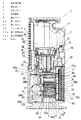
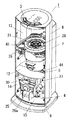
図1〜9に示す本実施形態の空気調和機1は、空気吸入口2と空気吐出口3とを連通させる送風経路4の途中に配設した遠心ファンによって空気吸入口2から室内空気を吸い込み、この吸い込んだ室内空気を脱臭すると共に室内空気に含まれる塵や埃等を捕集した後、空気吐出口3から吐出するものであって、空気清浄機として利用されるものである。   The air conditioner 1 according to this embodiment shown in FIGS. 1 to 9 sucks room air from the air suction port 2 by a centrifugal fan disposed in the middle of the air blowing path 4 that allows the air suction port 2 and the air discharge port 3 to communicate with each other. The sucked indoor air is deodorized and dust, dust, etc. contained in the indoor air are collected and then discharged from the air discharge port 3, and is used as an air purifier.

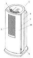
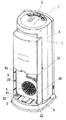
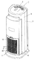
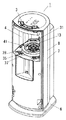
図2に示すように空気調和機1は床に載置されるベース6と、ベース6上に設けた本体部7にて構成されており、本体部7の外殻をなす縦長の器体8の天壁部及び該器体8の前壁部を構成する前カバー39の上部には空気吐出口3を形成している。また図3、図4に示すように器体8の後面部の下部には前方に凹む矩形状の凹部9を形成してあり、該凹部9により器体8の後面部の下部に形成された開口43には該開口43を覆うように上記空気吸入口2を有する吸込グリル10を着脱自在に取り付けている。   As shown in FIG. 2, the air conditioner 1 includes a base 6 placed on the floor and a main body 7 provided on the base 6, and a vertically long body 8 that forms an outer shell of the main body 7. The air discharge port 3 is formed in the upper part of the front cover 39 which comprises the top wall part and the front wall part of the vessel body 8. Further, as shown in FIGS. 3 and 4, a rectangular concave portion 9 that is recessed forward is formed in the lower portion of the rear surface portion of the container body 8, and the concave portion 9 is formed in the lower portion of the rear surface portion of the container body 8. A suction grill 10 having the air suction port 2 is detachably attached to the opening 43 so as to cover the opening 43.

凹部9内には空気吸入口2を内面側から覆うように清浄化フィルタ11を配設してあり、該清浄化フィルタ11は塵や埃を捕捉する集塵フィルタと臭い成分を吸着する活性炭フィルタとの2層で構成されている。   A cleaning filter 11 is disposed in the recess 9 so as to cover the air suction port 2 from the inner surface side. The cleaning filter 11 is a dust collection filter that traps dust and dust and an activated carbon filter that absorbs odor components. And two layers.

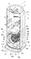
図5に示すように器体8の内部空間は後部の左右方向における一方の端部(図示例では右側端部)を除いて器体8内に配設した仕切り板12によって上下に仕切られており、これにより器体8の内部には仕切り板12よりも上位の前記空気吐出口3と連通する上位空間13と、仕切り板12よりも下位の下位空間14とが形成され、また仕切り板12の後部と器体8の側壁部との間に平面視で器体8の内部空間における後部の左右方向における一方の端部に位置する開口44が形成される。   As shown in FIG. 5, the internal space of the container body 8 is vertically divided by a partition plate 12 disposed in the container body 8 except for one end portion (right end portion in the illustrated example) in the left-right direction of the rear portion. Thus, an upper space 13 communicating with the air discharge port 3 higher than the partition plate 12 and a lower space 14 lower than the partition plate 12 are formed inside the container body 8. An opening 44 is formed between the rear portion and the side wall portion of the container body 8 at one end portion in the left-right direction of the rear portion in the internal space of the container body 8 in plan view.

上記凹部9の奥壁部9aの前方にある下位空間14は正面視で矩形状の空間であって、図1に示すように前側のファンモータ収納空間15と後側のファン収納空間16とからなり、ファン収納空間16は更に図6に示すように正面視で略C字状の隔壁17により渦室18と渦室18を除く部分である外側流路19とに仕切られている。   The lower space 14 in front of the rear wall portion 9a of the recess 9 is a rectangular space when viewed from the front. From the front fan motor storage space 15 and the rear fan storage space 16 as shown in FIG. As shown in FIG. 6, the fan storage space 16 is further divided into a vortex chamber 18 and an outer flow path 19 that is a portion excluding the vortex chamber 18 by a substantially C-shaped partition wall 17 in a front view.

上記略C字状の隔壁17は、左右方向において前記開口44とは反対側に位置して開口44側とは反対側に突となる半円分の弧の長さを有する半円弧状隔壁部17aと、左右方向において前記開口44側に位置して開口44側の斜め下方に突となる1/4円分の弧の長さを有する円弧状隔壁部17bと、器体8の底壁部における前記円弧状隔壁部17bと半円弧状隔壁部17aの間の部分と、器体8の左右方向における開口44側の側壁部とで構成されている。ここで半円弧状隔壁部17aはその上端を前記仕切り板12の後部の開口44側の端に一体に接続すると共にその下端を器体8の底壁部に接続してあり、また円弧状隔壁17bはその上端を器体8の左右方向における開口44側の側壁部に接続すると共にその下端を器体8の底壁部に接続してあり、半円弧状隔壁部17a及び円弧状隔壁部17bは共に凹部9の奥壁部9aから前方に突設してあるものとする。上記により隔壁17の内側に、正面視略円状のファン収納部18aと、ファン収納部18aと前記仕切り板12の開口44とを連通させる連通流路部18bと、で構成された渦室18が形成されることとなる。   The substantially C-shaped partition wall 17 is a semi-arc-shaped partition wall portion having a semicircular arc length located on the side opposite to the opening 44 in the left-right direction and projecting to the side opposite to the opening 44 side. 17a, an arcuate partition wall portion 17b having an arc length of ¼ circle located on the opening 44 side in the left-right direction and projecting obliquely downward on the opening 44 side, and a bottom wall portion of the vessel 8 The portion between the arc-shaped partition wall portion 17b and the semi-arc-shaped partition wall portion 17a and the side wall portion on the opening 44 side in the left-right direction of the body 8 are configured. Here, the semi-arc-shaped partition wall portion 17a is integrally connected at its upper end to the opening 44 side end of the rear portion of the partition plate 12, and its lower end is connected to the bottom wall portion of the body 8, and the arc-shaped partition wall 17b has an upper end connected to the side wall portion on the opening 44 side in the left-right direction of the vessel body 8 and a lower end connected to the bottom wall portion of the vessel body 8, and the semicircular partition wall portion 17a and the arc-shaped partition wall portion 17b. Are assumed to project forward from the back wall 9a of the recess 9. As described above, inside the partition wall 17, the vortex chamber 18 constituted by the fan storage portion 18 a having a substantially circular shape in front view, and the communication flow path portion 18 b communicating the fan storage portion 18 a and the opening 44 of the partition plate 12. Will be formed.

また上記半円弧状隔壁部17a及び円弧状隔壁部17bの夫々を介して渦室18の外側にある外側流路19は正面視で矩形状のファン収納空間16の四隅部の内、左右方向における開口44側且つ上側の一隅部を除く三隅部の夫々に形成された流路19a、19b、19cからなり、左右方向における開口44とは反対側且つ上側の隅部に形成された流路19aと、左右方向における開口44とは反対側且つ下側の隅部に形成された流路19bは連通している。   Further, the outer flow path 19 outside the vortex chamber 18 through the semicircular arc-shaped partition wall portion 17a and the arc-shaped partition wall portion 17b is located in the left and right directions in the four corners of the rectangular fan storage space 16 in front view. It consists of flow paths 19a, 19b, 19c formed at the three corners excluding the one corner on the opening 44 side, and a flow path 19a formed at the upper corner on the opposite side to the opening 44 in the left-right direction. The flow path 19b formed in the corner on the opposite side and the lower side of the opening 44 in the left-right direction is in communication.

上記渦室18のファン収納部18aには遠心ファンとして軸方向を前後方向とする略円筒状のシロッコファン5を回動自在に配設している。隔壁17によって周面部が囲まれたシロッコファン5は軸方向における両側の側面部を構成するエンドプレート20a、20bと、両エンドプレート20a、20b間に回転軸回りに間隔を介して架設したシロッコファン5の周面部を構成する複数枚の羽根21とで構成されており、両エンドプレート20の内、後側にある一方のエンドプレート20aの中央には第一吸込口としてシロッコファン5の回転軸方向に貫通する円形の主吸込口22を形成してある。また前側にある他方のエンドプレート20bの中心部には駆動軸接続部となる軸方向に貫通する駆動軸接続孔部23を形成してあり、エンドプレート20bの駆動軸接続孔部23よりも径方向外側に位置する外周部には第二吸込口として回転軸方向に貫通する副吸込口24を穿設している。ここで上記主吸込口22はシロッコファン5の周面部よりも径方向における内方に形成されており、また上記副吸込口24は回転軸廻りに間隔を介して配した複数の孔24aからなり、これら複数の孔24aは羽根21よりも径方向における内方に形成されているものとする。   In the fan housing portion 18a of the vortex chamber 18, a substantially cylindrical sirocco fan 5 having an axial direction in the front-rear direction as a centrifugal fan is rotatably disposed. The sirocco fan 5 surrounded by the partition wall 17 is a sirocco fan constructed between the end plates 20a, 20b constituting the side surfaces on both sides in the axial direction and between the end plates 20a, 20b with a space around the rotation axis. 5 and a plurality of blades 21 constituting the peripheral surface portion, and the rotation shaft of the sirocco fan 5 serves as a first suction port at the center of one end plate 20a on the rear side of both end plates 20. A circular main suction port 22 penetrating in the direction is formed. In addition, a drive shaft connection hole 23 penetrating in the axial direction as a drive shaft connection portion is formed at the center of the other end plate 20b on the front side, and the diameter is larger than that of the drive shaft connection hole 23 of the end plate 20b. A sub-suction port 24 penetrating in the rotation axis direction is provided as a second suction port in the outer peripheral portion located on the outer side in the direction. Here, the main suction port 22 is formed inward in the radial direction from the peripheral surface portion of the sirocco fan 5, and the sub suction port 24 is composed of a plurality of holes 24a arranged at intervals around the rotation axis. The plurality of holes 24 a are formed inward in the radial direction from the blades 21.

上記外側流路19及び渦室18に連通するファンモータ収納空間15はファン収納空間16のように仕切られておらず、このファンモータ収納空間15には図1に示すようにモータ本体25aと、モータ本体25aによって回転駆動するモータ本体25aから後方に突出した駆動軸25bと、からなるファンモータ25を配設している。ファンモータ25の駆動軸25bは渦室18のファン収納部18aに至るまで突出しており、該駆動軸25bの突端部は前記シロッコファン5の駆動軸接続孔部23に挿入されてナット26により固着されている。またファンモータ収納空間15にはファンモータ25よりも上位にファンモータ25や後述する静電霧化装置28の運転を制御する制御基板27を配設している。ここでモータ本体25aとシロッコファン5の間、及び制御基板27とシロッコファン5の間には夫々ファンモータ収納空間15と副吸込口24とを連通させる隙間が形成されているものとする。   The fan motor storage space 15 communicating with the outer flow path 19 and the vortex chamber 18 is not partitioned like the fan storage space 16, and the fan motor storage space 15 includes a motor main body 25a, as shown in FIG. A fan motor 25 including a drive shaft 25b protruding rearward from the motor body 25a that is rotationally driven by the motor body 25a is disposed. The drive shaft 25 b of the fan motor 25 protrudes to reach the fan housing portion 18 a of the vortex chamber 18, and the projecting end portion of the drive shaft 25 b is inserted into the drive shaft connection hole 23 of the sirocco fan 5 and fixed by the nut 26. Has been. In the fan motor storage space 15, a control board 27 for controlling the operation of the fan motor 25 and the electrostatic atomizer 28 described later is disposed above the fan motor 25. Here, it is assumed that gaps are formed between the motor body 25a and the sirocco fan 5 and between the control board 27 and the sirocco fan 5 so that the fan motor storage space 15 and the auxiliary suction port 24 communicate with each other.

そして図3に示すように前述した矩形状の凹部9の奥壁部9aにおけるシロッコファン5の主吸込口22に対応する部分である中央には複数の孔で構成された円形の主吸込孔部29を穿設してあり、これにより凹部9と主吸込孔部29とで構成された第一空気流路となる主空気流路31aが形成され、該主空気流路31aにより空気吸入口2とシロッコファン5の主吸込口22とが連通することとなる。また図3に示すように凹部9の奥壁部9aにおける矩形状のファン収納空間16の三隅部の夫々に形成された流路19a、19b、19cからなる外側流路19に対応する部分である下端部の左右方向における両端部と、上端部の左右方向における開口44とは反対側の半部の計3箇所の夫々には複数のスリット孔からなる副吸込孔部32を穿設してあり、これにより凹部9と副吸込孔部32と外側流路19とで構成された第二空気流路となる副空気流路31bが形成され、該副空気流路31bにより空気吸入口2とシロッコファン5の副吸込口24とが連通することとなる。そして本実施形態ではシロッコファン5よりも上流側の上流側流路30とシロッコファン5よりも下流側の下流側流路31とで構成された送風経路4の内、上流側流路30を上記主空気流路31aと副空気流路31bとで構成してあり、下流側流路31を上記連通流路部18bと上位空間13とで構成してある。   And as shown in FIG. 3, the circular main suction hole part comprised in the center which is a part corresponding to the main suction inlet 22 of the sirocco fan 5 in the back wall part 9a of the rectangular recessed part 9 mentioned above is comprised. 29 is formed, thereby forming a main air flow path 31a serving as a first air flow path constituted by the recess 9 and the main suction hole 29, and the air intake port 2 is formed by the main air flow path 31a. And the main suction port 22 of the sirocco fan 5 communicate with each other. Further, as shown in FIG. 3, it is a portion corresponding to the outer flow path 19 including flow paths 19 a, 19 b, and 19 c formed at the three corners of the rectangular fan storage space 16 in the back wall section 9 a of the recess 9. Sub-suction hole portions 32 each having a plurality of slit holes are formed in a total of three locations, ie, both ends of the lower end portion in the left-right direction and the half portion opposite to the opening 44 in the left-right direction of the upper end portion. As a result, a sub air flow path 31b, which is a second air flow path constituted by the recess 9, the sub suction hole 32, and the outer flow path 19, is formed, and the air suction port 2 and the sirocco are formed by the sub air flow path 31b. The sub suction port 24 of the fan 5 communicates. In the present embodiment, the upstream flow path 30 of the air flow path 4 constituted by the upstream flow path 30 upstream of the sirocco fan 5 and the downstream flow path 31 downstream of the sirocco fan 5 is described above. The main air flow path 31 a and the sub air flow path 31 b are configured, and the downstream flow path 31 is configured by the communication flow path portion 18 b and the upper space 13.

今、前述したファンモータ25を運転しシロッコファン5を回転駆動した場合、室内空気は空気吸入口2から清浄化フィルタ11を通り、該清浄化フィルタ11にて清浄化された後、凹部9内に流入する。そしてこの凹部9内に流入した空気の内、一部は図1の矢印イに示すように主吸込孔部29から渦室18のファン収納部18aに流入し、この後シロッコファン5の主吸込口22からシロッコファン5内に流入し、また他部は図1及び図6の矢印ロに示すように副吸込孔部32から外側流路19に流入し、この後外側流路19を通ってファンモータ収納空間15に流入し、次いで渦室18のファン収納部18aに流入してシロッコファン5の副吸込口24からシロッコファン5内に流入する。そしてこの主吸込口22及び副吸込口24から別々にシロッコファン5に流入した空気の全部はシロッコファン5の回転軸回りに隣接する羽根21間に形成された吹出口40を通って連通流路部18bを介して上位空間13に流入し、この後空気吐出口3より室内に吐出される。   Now, when the fan motor 25 described above is operated and the sirocco fan 5 is driven to rotate, the room air passes through the cleaning filter 11 from the air suction port 2 and is cleaned by the cleaning filter 11, and then the interior of the recess 9. Flow into. A part of the air flowing into the recess 9 flows into the fan housing portion 18a of the vortex chamber 18 from the main suction hole 29 as shown by an arrow A in FIG. 1, and thereafter the main suction of the sirocco fan 5 It flows into the sirocco fan 5 from the opening 22, and the other part flows into the outer flow path 19 from the auxiliary suction hole 32 as shown by the arrow b in FIGS. 1 and 6, and then passes through the outer flow path 19. It flows into the fan motor storage space 15, then flows into the fan storage portion 18 a of the vortex chamber 18, and flows into the sirocco fan 5 from the auxiliary suction port 24 of the sirocco fan 5. All of the air separately flowing into the sirocco fan 5 from the main suction port 22 and the sub suction port 24 passes through the blowout port 40 formed between the adjacent blades 21 around the rotation axis of the sirocco fan 5. It flows into the upper space 13 via the part 18b and is then discharged into the room through the air discharge port 3.

上記のように本実施形態の空気調和機1は、空気吸入口2と主吸込口22とを主空気流路31aにより連通させてあるので、従来と同様にシロッコファン5の主吸込口22から吸い込んだ空気をシロッコファン5の径方向外側に向かって吹き出すことができるのは勿論、加えてシロッコファン5には上記軸方向における一方の側面部(エンドプレート20a)の中央に設けてある主吸込口22とは別に副吸込口24を設けて、この副吸込口24と空気吸入口2とを副空気流路31bにて連通させているので、シロッコファン5への空気供給量が増加し、これによりシロッコファン5で効率良く空気を送風できて送風量を増大させることができ、従って小型で送風能力が低いシロッコファン5を用いて室内全域にまんべんなく調和空気を循環させることができて、空気調和機1の小型化、静音化、省エネ化が図れる。さらにシロッコファン5への空気供給量を増大させるために設けた上記副空気流路31bには冷却が必要となる部品であるファンモータ25及び制御基板27を配設してあるので、運転により発熱したファンモータ25及び制御基板27を副空気流路31bを通る空気により冷却することができ、ファンモータ25及び制御基板27の故障を防止でき、しかもこの場合、主空気流路31aには流路抵抗となるものが配設されておらず、主空気流路11からシロッコファン5に供給される空気供給量が低下することがない。さらに本実施形態ではシロッコファン5の軸方向における一方の側面部(エンドプレート20a)の中央に主吸込口22を形成し、他方の側面部(エンドプレート20b)の中心部には駆動軸接続孔部23を設け、シロッコファン5の他方の側面部の駆動軸接続孔部23が設けられていない駆動軸接続孔部23よりも径方向外側に位置する外周部に副吸込口24を形成してあるので、従来同様主吸込口22からシロッコファン5内に流入した空気はスムーズに径方向外側に誘導されて吐出されることとなる。また本実施形態では前述したように外側流路19を構成する流路19a、19b、19cを正面視矩形状のファン収納空間16において渦室18を除くデッドスペースとなる三隅部に夫々形成してあるので空気調和機1を更に小型化できる。なお本実施形態では上流側流路30の上流側端部で異なる二流路に分岐して、この分岐点よりも下流側を主空気流路31aと副空気流路31bとで構成した例を示したが、器体8の異なる位置に夫々空気吸入口2を設け、送風経路4の上流側流路30を、一方の空気吸入口2と主吸込口22とを連通させる主空気流路と他方の空気吸入口2と副吸込口とを連通させる副空気流路とで構成しても良いものとする。   As described above, in the air conditioner 1 of the present embodiment, since the air suction port 2 and the main suction port 22 are communicated with each other by the main air flow path 31a, the main suction port 22 of the sirocco fan 5 is connected as in the conventional case. Of course, the sucked air can be blown out radially outward of the sirocco fan 5, and in addition, the sirocco fan 5 has a main suction provided at the center of one side surface (end plate 20a) in the axial direction. Since the sub suction port 24 is provided separately from the port 22 and the sub suction port 24 and the air suction port 2 are communicated with each other through the sub air flow path 31b, the amount of air supplied to the sirocco fan 5 increases. As a result, air can be efficiently blown by the sirocco fan 5 and the amount of blown air can be increased. Therefore, the sirocco fan 5 having a small size and low blowing ability is used to circulate conditioned air evenly throughout the room. And be Rukoto, miniaturization of the air conditioner 1, noise reduction, the energy saving achieved. Further, the sub motor air flow path 31b provided to increase the amount of air supplied to the sirocco fan 5 is provided with the fan motor 25 and the control board 27, which are parts that need to be cooled. The fan motor 25 and the control board 27 can be cooled by the air passing through the sub air flow path 31b, and the failure of the fan motor 25 and the control board 27 can be prevented. In this case, the main air flow path 31a has a flow path. No resistor is provided, and the amount of air supplied from the main air flow path 11 to the sirocco fan 5 does not decrease. Further, in the present embodiment, a main suction port 22 is formed at the center of one side surface (end plate 20a) in the axial direction of the sirocco fan 5, and a drive shaft connection hole is formed at the center of the other side surface (end plate 20b). The auxiliary suction port 24 is formed in the outer peripheral portion located radially outside the drive shaft connection hole 23 where the drive shaft connection hole 23 on the other side surface portion of the sirocco fan 5 is not provided. Therefore, the air flowing into the sirocco fan 5 from the main suction port 22 is smoothly guided to the outside in the radial direction and discharged as in the conventional case. In the present embodiment, as described above, the flow paths 19a, 19b, and 19c constituting the outer flow path 19 are respectively formed at the three corners that are dead spaces except for the vortex chamber 18 in the rectangular fan housing space 16 in front view. Therefore, the air conditioner 1 can be further downsized. In the present embodiment, an example is shown in which the upstream end of the upstream flow passage 30 is branched into two different flow passages, and the downstream side of the branch point is constituted by the main air flow passage 31a and the sub air flow passage 31b. However, the air suction port 2 is provided at a different position of the vessel body 8, and the upstream air flow path 30 of the air blowing path 4 is connected to the main air flow path that connects the one air suction port 2 and the main suction port 22 to the other. The air suction port 2 and the sub suction port may be configured to communicate with each other.

また本実施形態の空気調和機1には図7等に示すように上記送風経路4のシロッコファン5よりも下流側、具体的には上位空間13の下部に静電霧化装置28を配設してあり、該静電霧化装置28により空気吸入口2より流入した室内空気の脱臭効果を高めると共に室内の壁やカーテン等に付着した臭気成分を除去できるようにしている。   Further, in the air conditioner 1 of the present embodiment, as shown in FIG. 7 and the like, an electrostatic atomizer 28 is disposed downstream of the sirocco fan 5 in the air blowing path 4, specifically, in the lower part of the upper space 13. Thus, the electrostatic atomizer 28 enhances the deodorizing effect of the indoor air flowing in from the air inlet 2 and removes the odor components adhering to the indoor walls and curtains.

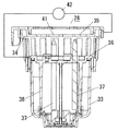
図8に示す静電霧化装置28は霧化させることになる水を収容したカップ状の水溜部33と、円筒状で且つ周面に通風孔が開口するホルダー34と、該ホルダー34の上部に配された対向電極35と、ホルダー34の下部に嵌め込まれて水に対する電圧印加を担う印加電極36と、この印加電極36によって保持されている複数本の棒状の搬送部37とで構成されており、静電霧化装置28の下部に設けた上記水溜部33は上端部が上記ホルダー34の下部に装着されている印加電極36に着脱自在に取り付けられている。   An electrostatic atomizer 28 shown in FIG. 8 has a cup-shaped water reservoir 33 containing water to be atomized, a cylindrical holder 34 with a vent hole in the circumferential surface, and an upper portion of the holder 34. A counter electrode 35 disposed in the holder 34, an application electrode 36 that is fitted in the lower part of the holder 34 and applies a voltage to water, and a plurality of rod-shaped transport units 37 held by the application electrode 36. The water reservoir 33 provided in the lower part of the electrostatic atomizer 28 is detachably attached to the application electrode 36 attached to the lower part of the holder 34 at the upper end.

対向電極35と印加電極36は共にカーボンのような導電材を混入した合成樹脂やSUSのような金属で形成されることで導電性を有しているもので、ホルダー34の上部に被せられる対向電極35は接地され、また印加電極36は器体1に内装した電圧印加部42となる高電圧発生源に接続されている。   Both the counter electrode 35 and the application electrode 36 are made of a synthetic resin mixed with a conductive material such as carbon or a metal such as SUS, and have conductivity. The electrode 35 is grounded, and the application electrode 36 is connected to a high voltage generation source serving as a voltage application unit 42 built in the container 1.

搬送部37は多孔質セラミックで形成されてその上端が針状に尖ったもので、これら搬送部37は上部が印加電極36よりも上方に突出し、下部は下方に突出して上記水溜部33内に入れられた水と接触している。   The transport unit 37 is made of porous ceramic and has an upper end pointed like a needle. The transport unit 37 has an upper part projecting upward from the application electrode 36 and a lower part projecting downward to enter the water reservoir 33. In contact with water.

図8中38は印加電極36から下方に突出している円筒状のスカートで、上記複数本の搬送部37の外側を囲んでおり、その下端は搬送部37の下端よりも下方に位置している。印加電極36における該スカート38は水溜部33内に入れられた水と接触することで水に高電圧を印加すると同時にセラミックで形成されている搬送部37の保護を行うものである。ここでスカート22の周方向の一部にはスカート22の上下方向全長にわたるスリットを設けているものとする。   In FIG. 8, reference numeral 38 denotes a cylindrical skirt that protrudes downward from the application electrode 36, and surrounds the outside of the plurality of transport units 37, and the lower end thereof is positioned below the lower end of the transport unit 37. . The skirt 38 in the application electrode 36 is in contact with water contained in the water reservoir 33 so as to apply a high voltage to the water and at the same time protect the transport unit 37 formed of ceramic. Here, a part of the skirt 22 in the circumferential direction is provided with a slit extending over the entire length of the skirt 22 in the vertical direction.

ホルダー34の上面開口を閉じるように装着された対向電極35は、図7に示すように中央に開口部41を有するとともに、この開口部41の縁は上方から見た時、前記複数本の搬送部37の上端の針状部を中心とする複数の同一径の円弧を他の円弧で滑らかにつないだものとなっている。対向電極35を接地し、印加電極36に高電圧発生源を接続するとともに、搬送部37が毛細管現象で水を吸い上げている時、搬送部37の上端の針状部が印加電極36側の実質的な電極として機能すると同時に、対向電極35の上記円弧が実質的な電極として機能するものである。   The counter electrode 35 mounted so as to close the upper surface opening of the holder 34 has an opening 41 in the center as shown in FIG. 7, and the edge of the opening 41 when viewed from above is the plurality of transports. A plurality of arcs of the same diameter centered on the needle-like portion at the upper end of the portion 37 are smoothly connected by other arcs. The counter electrode 35 is grounded, a high voltage source is connected to the application electrode 36, and when the transport unit 37 sucks up water by capillary action, the needle-like portion at the upper end of the transport unit 37 is substantially on the application electrode 36 side. At the same time, the arc of the counter electrode 35 functions as a substantial electrode.

そして上記印加電極36のスカートに水を接触させると同時に、搬送部37に毛細管現象で水を吸い上げさせ、さらに電圧印加部42により対向電極35及び印加電極36間に電圧を印加した時、この電圧が水にレイリー分裂を起こさせることができる高電圧であれば、搬送部37の上端の針状部に達した水はここでレイリー分裂を起こしてナノメータサイズの粒子径の霧化を生じさせる静電霧化がなされるようになっており、これにより静電霧化装置28から送風経路4にナノメータサイズの帯電ミストが吹き出されることとなる。   Then, when water is brought into contact with the skirt of the application electrode 36, the transport unit 37 sucks up the water by capillary action, and when a voltage is applied between the counter electrode 35 and the application electrode 36 by the voltage application unit 42, this voltage is applied. Is a high voltage capable of causing Rayleigh splitting in the water, the water that has reached the needle-like portion at the upper end of the transport unit 37 will now cause Rayleigh splitting and atomization of a nanometer-sized particle diameter. Electromist atomization is performed, and as a result, nanometer-sized charged mist is blown out from the electrostatic atomizer 28 to the air blowing path 4.

上記のように送風経路4の下流側に静電霧化装置28を配設することで、空気吸入口2から吸い込まれた室内空気を静電霧化で生じたナノメータサイズの帯電ミストにより脱臭することができ、さらにはこの帯電ミストをシロッコファン5による送風に乗せて、帯電ミストを含んだ室内空気を空気吐出口3から室内に吐出することができ、これにより帯電ミストが有している活性種により室内空気中の臭気成分、特に室内壁面やカーテン等へ付着した臭気成分物を除去することができる。   By disposing the electrostatic atomizer 28 on the downstream side of the air blowing path 4 as described above, the indoor air sucked from the air suction port 2 is deodorized by the nanometer-size charged mist generated by electrostatic atomization. Furthermore, this charged mist can be put on the air blown by the sirocco fan 5 and the room air containing the charged mist can be discharged into the room from the air discharge port 3. Odor components in indoor air, particularly odor component adhering to indoor wall surfaces and curtains, can be removed by the seeds.

なお本実施形態では上記したように空気調和機を室内空気の脱臭及び室内空気に含まれる塵や埃を捕集する空気調和機1としたが、これに限定されず、例えば熱交換器を備えて冷房や除湿を行う空気調和機に上記技術を適用しても良いものとする。   In the present embodiment, as described above, the air conditioner is the air conditioner 1 that deodorizes indoor air and collects dust and dirt contained in the indoor air. However, the present invention is not limited thereto, and includes, for example, a heat exchanger. The above technique may be applied to an air conditioner that performs cooling and dehumidification.

本発明の実施の形態の一例を示し、図は空器調和機の側断面図である。An example of embodiment of this invention is shown and the figure is a sectional side view of an air conditioner. 同上の空気調和機の正面斜視図である。It is a front perspective view of an air conditioner same as the above. 同上の空気調和機の吸込グリルを取り外した背面斜視図である。It is the back perspective view which removed the suction grill of the air harmony machine same as the above. 同上の空気調和機の背面斜視図である。It is a back perspective view of an air conditioner same as the above. 同上の空気調和機の前面部の図示を省略した正面斜視図である。It is a front perspective view which omitted illustration of the front part of an air harmony machine same as the above. 同上の第2空気流路を通る空気の流れを示すものであり、図は空気調和機の前面側の部品の図示を省略した正面斜視図である。The flow of the air which passes along the 2nd air flow path same as the above is shown, The figure is a front perspective view which abbreviate | omitted illustration of the components of the front side of an air conditioner. 同上の前カバーを取り外した状態を示す空気調和機の正面斜視図である。It is a front perspective view of the air conditioner which shows the state which removed the front cover same as the above. 同上の静電霧化装置を示す側断面図である。It is a sectional side view which shows an electrostatic atomizer same as the above. 同上の空気調和機の正面図である。It is a front view of an air conditioner same as the above.

符号の説明Explanation of symbols

1 空気調和機
2 空気吸入口
3 空気吐出口
4 送風経路
5 遠心ファン
22 第一吸込口
24 第二吸込口
25 ファンモータ
25b 駆動軸
28 静電霧化装置
31a 第一空気流路
31b 第二空気流路
33 水溜部
35 対向電極
36 印加電極
37 搬送部
40 吹出口
42 電圧印加部
DESCRIPTION OF SYMBOLS 1 Air conditioner 2 Air inlet 3 Air outlet 4 Air supply path 5 Centrifugal fan 22 First inlet 24 Second inlet 25 Fan motor 25b Drive shaft 28 Electrostatic atomizer 31a First air flow path 31b Second air Channel 33 Water reservoir 35 Counter electrode 36 Application electrode 37 Transport unit 40 Air outlet 42 Voltage application unit

Claims (3)

空気吸入口と空気吐出口を連通させる送風経路の途中にファンモータにより回転駆動して空気吸入口から空気を吸い込むと共にこの吸い込んだ空気を空気吐出口から吹き出す遠心ファンを備え、遠心ファンに第一吸込口及び第二吸込口を形成すると共に前記第一吸込口及び第二吸込口から吸い込んだ空気を遠心ファンの径方向外側に向かって吹き出す吹出口を形成し、送風経路における遠心ファンよりも上流側を、前記遠心ファンの第一吸込口と空気吸入口とを連通させる第一空気流路と、第二吸込口と空気吸入口とを連通させる第二空気流路とで構成して成ることを特徴とする空気調和機。   The centrifugal fan is equipped with a centrifugal fan that is driven to rotate by a fan motor and sucks air from the air suction port and blows out the sucked air from the air discharge port in the middle of the air passage that connects the air suction port and the air discharge port. Forms a suction port and a second suction port, and forms a blowout port for blowing out air sucked from the first suction port and the second suction port toward the outside in the radial direction of the centrifugal fan, and is upstream of the centrifugal fan in the air flow path The side is composed of a first air flow path that communicates the first suction port and the air suction port of the centrifugal fan, and a second air flow channel that communicates the second suction port and the air suction port. Air conditioner characterized by. 水溜部と、水溜部から水を搬送する多孔質部材によって形成された搬送部と、該搬送部の搬送方向の端部に対向する対向電極と、水溜部から搬送部の搬送方向の端に至る経路中の水に電圧を印加する印加電極と、を備えて、電圧印加部により前記印加電極と対向電極間に高電圧を印加することで静電霧化がなされる静電霧化装置を備え、該静電霧化装置を送風経路の遠心ファンよりも下流側に配設して成ることを特徴とする請求項1記載の空気調和機。   A water reservoir, a transport portion formed by a porous member that transports water from the water reservoir, a counter electrode facing an end of the transport portion in the transport direction, and the water reservoir to the end of the transport portion in the transport direction An application electrode that applies a voltage to water in the path, and an electrostatic atomization device that performs electrostatic atomization by applying a high voltage between the application electrode and the counter electrode by a voltage application unit. 2. The air conditioner according to claim 1, wherein the electrostatic atomizer is disposed downstream of the centrifugal fan in the air passage. 遠心ファンの回転軸方向における一方の側面部の中央に第一吸込口を形成し、他方の側面部の中心部に駆動軸接続部を設け、該駆動軸接続部に遠心ファンの他方の側面部側に配設したファンモータの駆動軸を接続し、前記遠心ファンの他方の側面部の駆動軸接続部よりも径方向外側に位置する外周部に第二吸込口を形成して成ることを特徴とする請求項1又は請求項2記載の空気調和機。   A first suction port is formed at the center of one side surface portion in the rotation axis direction of the centrifugal fan, a drive shaft connection portion is provided at the center portion of the other side surface portion, and the other side surface portion of the centrifugal fan is provided at the drive shaft connection portion. A drive shaft of a fan motor disposed on the side is connected, and a second suction port is formed in an outer peripheral portion located radially outside the drive shaft connection portion on the other side surface portion of the centrifugal fan. The air conditioner according to claim 1 or 2.
JP2004107307A 2004-03-31 2004-03-31 Air conditioner Expired - Fee Related JP4670250B2 (en)

Priority Applications (1)

Application Number Priority Date Filing Date Title
JP2004107307A JP4670250B2 (en) 2004-03-31 2004-03-31 Air conditioner

Applications Claiming Priority (1)

Application Number Priority Date Filing Date Title
JP2004107307A JP4670250B2 (en) 2004-03-31 2004-03-31 Air conditioner

Publications (2)

Publication Number Publication Date
JP2005291625A true JP2005291625A (en) 2005-10-20
JP4670250B2 JP4670250B2 (en) 2011-04-13

Family

ID=35324746

Family Applications (1)

Application Number Title Priority Date Filing Date
JP2004107307A Expired - Fee Related JP4670250B2 (en) 2004-03-31 2004-03-31 Air conditioner

Country Status (1)

Country Link
JP (1) JP4670250B2 (en)

Cited By (6)

* Cited by examiner, † Cited by third party
Publication number Priority date Publication date Assignee Title
KR100829992B1 (en) 2007-02-02 2008-05-16 (주)에이티앤비 Low-Noise air exhauster
JP2009293830A (en) * 2008-06-03 2009-12-17 Tiger Vacuum Bottle Co Ltd Humidifier
JP2011031202A (en) * 2009-08-04 2011-02-17 Panasonic Corp Electrostatic atomization device
JP2016095097A (en) * 2014-11-14 2016-05-26 象印マホービン株式会社 Blower
CN109442583A (en) * 2018-10-25 2019-03-08 Tcl空调器(中山)有限公司 A kind of window air conditioner
CN113494748A (en) * 2020-03-20 2021-10-12 广东美的环境电器制造有限公司 Humidifying device

Citations (4)

* Cited by examiner, † Cited by third party
Publication number Priority date Publication date Assignee Title
JPH01168315A (en) * 1987-12-23 1989-07-03 Matsushita Electric Works Ltd Air cleaner
JPH1151429A (en) * 1997-07-31 1999-02-26 Matsushita Electric Works Ltd Air cleaner
JP2002295872A (en) * 2001-03-30 2002-10-09 Mitsubishi Electric Corp Humidifier
JP2004085185A (en) * 2002-06-25 2004-03-18 Matsushita Electric Works Ltd Air cleaner

Patent Citations (4)

* Cited by examiner, † Cited by third party
Publication number Priority date Publication date Assignee Title
JPH01168315A (en) * 1987-12-23 1989-07-03 Matsushita Electric Works Ltd Air cleaner
JPH1151429A (en) * 1997-07-31 1999-02-26 Matsushita Electric Works Ltd Air cleaner
JP2002295872A (en) * 2001-03-30 2002-10-09 Mitsubishi Electric Corp Humidifier
JP2004085185A (en) * 2002-06-25 2004-03-18 Matsushita Electric Works Ltd Air cleaner

Cited By (7)

* Cited by examiner, † Cited by third party
Publication number Priority date Publication date Assignee Title
KR100829992B1 (en) 2007-02-02 2008-05-16 (주)에이티앤비 Low-Noise air exhauster
JP2009293830A (en) * 2008-06-03 2009-12-17 Tiger Vacuum Bottle Co Ltd Humidifier
JP2011031202A (en) * 2009-08-04 2011-02-17 Panasonic Corp Electrostatic atomization device
JP2016095097A (en) * 2014-11-14 2016-05-26 象印マホービン株式会社 Blower
CN109442583A (en) * 2018-10-25 2019-03-08 Tcl空调器(中山)有限公司 A kind of window air conditioner
CN113494748A (en) * 2020-03-20 2021-10-12 广东美的环境电器制造有限公司 Humidifying device
CN113494748B (en) * 2020-03-20 2023-03-17 广东美的环境电器制造有限公司 Humidifying device

Also Published As

Publication number Publication date
JP4670250B2 (en) 2011-04-13

Similar Documents

Publication Publication Date Title
JP4701746B2 (en) Air conditioner with air purification function
JP4470710B2 (en) Air conditioner for vehicles
US7387664B2 (en) Wet type air cleaner
US20060230713A1 (en) Wet type air cleaner
WO2013047134A2 (en) Air purifier, and method for using air purifier
JP4096905B2 (en) Air conditioner
JP4551288B2 (en) Air conditioner
JP4670250B2 (en) Air conditioner
JP2003056873A (en) Electric space heater with humidifying function
US20060102002A1 (en) Cleaning unit for wet type air cleaner
JP2010091262A (en) Air conditioner
KR101565094B1 (en) Air Purifier
KR100335324B1 (en) Vacuum cleaner of air circulation type
JP6020805B2 (en) Air cleaner
JP5149765B2 (en) Deodorization device
JP5556341B2 (en) Air purifier
JP5066053B2 (en) Deodorization device
WO2013046994A1 (en) Cleaning robot
JP4085710B2 (en) Air cleaner
JP4649846B2 (en) Electrostatic atomizer and air cleaner provided with the same
JP2008045798A (en) Indoor unit of air conditioner
JP5249893B2 (en) Panel device
JP2003262368A (en) Anion generating device
JP2014117299A (en) Deodorizing apparatus
JP2006100218A (en) Lighting apparatus

Legal Events

Date Code Title Description
A621 Written request for application examination

Free format text: JAPANESE INTERMEDIATE CODE: A621

Effective date: 20061222

A977 Report on retrieval

Free format text: JAPANESE INTERMEDIATE CODE: A971007

Effective date: 20091130

A131 Notification of reasons for refusal

Free format text: JAPANESE INTERMEDIATE CODE: A131

Effective date: 20091208

A521 Request for written amendment filed

Free format text: JAPANESE INTERMEDIATE CODE: A523

Effective date: 20100208

A131 Notification of reasons for refusal

Free format text: JAPANESE INTERMEDIATE CODE: A131

Effective date: 20100608

A521 Request for written amendment filed

Free format text: JAPANESE INTERMEDIATE CODE: A523

Effective date: 20100809

RD04 Notification of resignation of power of attorney

Free format text: JAPANESE INTERMEDIATE CODE: A7424

Effective date: 20100809

TRDD Decision of grant or rejection written
A01 Written decision to grant a patent or to grant a registration (utility model)

Free format text: JAPANESE INTERMEDIATE CODE: A01

Effective date: 20101221

A01 Written decision to grant a patent or to grant a registration (utility model)

Free format text: JAPANESE INTERMEDIATE CODE: A01

A61 First payment of annual fees (during grant procedure)

Free format text: JAPANESE INTERMEDIATE CODE: A61

Effective date: 20110103

FPAY Renewal fee payment (event date is renewal date of database)

Free format text: PAYMENT UNTIL: 20140128

Year of fee payment: 3

LAPS Cancellation because of no payment of annual fees