JP2005291530A - Spray drying device, powder drying method, and method of manufacturing ferrite particle - Google Patents
Spray drying device, powder drying method, and method of manufacturing ferrite particle Download PDFInfo
- Publication number
- JP2005291530A JP2005291530A JP2004103182A JP2004103182A JP2005291530A JP 2005291530 A JP2005291530 A JP 2005291530A JP 2004103182 A JP2004103182 A JP 2004103182A JP 2004103182 A JP2004103182 A JP 2004103182A JP 2005291530 A JP2005291530 A JP 2005291530A
- Authority
- JP
- Japan
- Prior art keywords
- drying
- hot air
- spray
- outlet
- wall
- Prior art date
- Legal status (The legal status is an assumption and is not a legal conclusion. Google has not performed a legal analysis and makes no representation as to the accuracy of the status listed.)
- Withdrawn
Links
- 238000001035 drying Methods 0.000 title claims abstract description 125
- 238000001694 spray drying Methods 0.000 title claims abstract description 57
- 239000000843 powder Substances 0.000 title claims abstract description 18
- 238000004519 manufacturing process Methods 0.000 title claims abstract description 8
- 229910000859 α-Fe Inorganic materials 0.000 title claims description 46
- 239000002245 particle Substances 0.000 title description 12
- 230000002093 peripheral effect Effects 0.000 claims abstract description 32
- 238000007664 blowing Methods 0.000 claims abstract description 17
- 238000004080 punching Methods 0.000 claims abstract description 10
- 239000011550 stock solution Substances 0.000 claims description 16
- 239000007788 liquid Substances 0.000 abstract description 10
- 239000002002 slurry Substances 0.000 description 38
- 239000000463 material Substances 0.000 description 10
- 238000000034 method Methods 0.000 description 9
- 239000002994 raw material Substances 0.000 description 8
- 230000000694 effects Effects 0.000 description 6
- 238000005507 spraying Methods 0.000 description 6
- 238000009825 accumulation Methods 0.000 description 5
- 239000010419 fine particle Substances 0.000 description 5
- 239000008187 granular material Substances 0.000 description 5
- 230000015572 biosynthetic process Effects 0.000 description 4
- 238000010586 diagram Methods 0.000 description 4
- 239000000428 dust Substances 0.000 description 4
- 239000002904 solvent Substances 0.000 description 4
- 239000007921 spray Substances 0.000 description 3
- 239000002184 metal Substances 0.000 description 2
- 239000000126 substance Substances 0.000 description 2
- 240000003473 Grevillea banksii Species 0.000 description 1
- 241001417527 Pempheridae Species 0.000 description 1
- 238000013459 approach Methods 0.000 description 1
- 238000000889 atomisation Methods 0.000 description 1
- 230000004323 axial length Effects 0.000 description 1
- 238000001354 calcination Methods 0.000 description 1
- 230000000052 comparative effect Effects 0.000 description 1
- 238000013329 compounding Methods 0.000 description 1
- 239000004020 conductor Substances 0.000 description 1
- 230000007613 environmental effect Effects 0.000 description 1
- 230000014759 maintenance of location Effects 0.000 description 1
- 238000002156 mixing Methods 0.000 description 1
- 238000010298 pulverizing process Methods 0.000 description 1
- 239000000243 solution Substances 0.000 description 1
- 238000003756 stirring Methods 0.000 description 1
- 238000003260 vortexing Methods 0.000 description 1
- XLYOFNOQVPJJNP-UHFFFAOYSA-N water Substances O XLYOFNOQVPJJNP-UHFFFAOYSA-N 0.000 description 1
- 238000004804 winding Methods 0.000 description 1
Images
Landscapes
- Drying Of Solid Materials (AREA)
- Vaporization, Distillation, Condensation, Sublimation, And Cold Traps (AREA)
- Glanulating (AREA)
Abstract
Description
本発明は、噴霧乾燥装置、粉体の乾燥方法およびフェライト粒の製造方法に関する。 The present invention relates to a spray drying apparatus, a powder drying method, and a ferrite grain manufacturing method.
噴霧乾燥装置は、非特許文献1等にあるように、(i)液状の原料を微粒化し、乾燥筒内に分散させ、(ii)熱風発生装置からの熱風に効果的に接触させ、(iii)乾燥筒内で液滴から粉粒体に造粒・乾燥し、(iv)その粉粒体をガスから分離、回収して製品とする装置である。 As described in Non-Patent Document 1, etc., the spray drying apparatus (i) atomizes a liquid raw material and disperses it in a drying cylinder, (ii) effectively contacts hot air from a hot air generator, and (iii) This is a device that granulates and dries from droplets to powder in a drying cylinder, and (iv) separates and collects the particles from gas to produce a product.
また、噴霧乾燥用微粒化装置には、大きく分けて、回転ディスク方式と加圧ノズル方式がある。本発明の対象設備は、回転ディスク方式の噴霧乾燥用微粒化装置を備えた装置である。 In addition, atomization apparatuses for spray drying are roughly classified into a rotating disk method and a pressure nozzle method. The target equipment of the present invention is an apparatus including a rotary disk type spray drying atomizer.
特に回転ディスク方式の装置においては、乾燥筒の内壁に、粉粒体が凝集して付着しやすい。この乾燥筒内壁に付着した凝集物を除去する方法としては、特許文献1に示すようなエアースイーパー装置が考案されている。この装置では、乾燥筒内壁面に附着した凝集物を吹き落とす為に、一定のピッチで穴の開いたパイプを、一定速度で回転させ、パイプに圧縮空気を送り、その風圧で附着物を除去する。 In particular, in a rotating disk type apparatus, powder particles are likely to aggregate and adhere to the inner wall of the drying cylinder. As a method for removing the agglomerates adhering to the inner wall of the dry cylinder, an air sweeper as shown in Patent Document 1 has been devised. In this device, in order to blow off the agglomerates attached to the inner wall of the drying cylinder, a pipe with holes at a constant pitch is rotated at a constant speed, compressed air is sent to the pipe, and the attachment is removed by the wind pressure. To do.
また、乾燥筒壁面からの加圧空気吹き付け方法に関しては、特許文献2に示すように、多孔性フィルターの目詰まりを壁の外側から加圧空気を吹き付けることにより除去する方法が考案されている。また、乾燥筒内の円錐部への堆積除去の為に気流を導入する方法としては、特許文献3にて示されている。
本発明は、このような実状に鑑みてなされ、その目的は、回転ディスクを使用する噴霧乾燥装置において、乾燥筒内付着物を極力抑え、収率を上げることができる噴霧乾燥装置を提供することである。また同じ噴霧乾燥設備でも、乾燥物処理量を上げる乾燥方法とフェライト粒の製造方法を提供することである。 The present invention has been made in view of such a situation, and an object of the present invention is to provide a spray drying apparatus that can suppress deposits in a drying cylinder as much as possible and increase the yield in a spray drying apparatus that uses a rotating disk. It is. Another object of the present invention is to provide a drying method and a ferrite grain manufacturing method for increasing the amount of dried product even in the same spray drying equipment.
上記目的を達成するために、本発明に係る噴霧乾燥装置は、
粉体を作るための原液を、微小液滴となるように、乾燥筒体の上方中心部に設けられた回転ディスクから前記乾燥筒体の内壁に向けて放射状に噴霧し、噴霧された前記微小液滴を、乾燥用熱風で乾燥し、原液から直ちに粉体を製造する噴霧乾燥装置において、
前記微小液滴が放射状に噴霧される前記乾燥筒体の内壁には、前記乾燥用熱風の少なくとも一部が吹き出される周囲吹出口が、前記乾燥筒体の内壁の全周に沿って具備してあることを特徴とする。
In order to achieve the above object, a spray drying apparatus according to the present invention comprises:
The stock solution for making the powder is sprayed radially from the rotating disk provided at the upper central portion of the drying cylinder toward the inner wall of the drying cylinder so as to be a fine droplet, and the sprayed micro In a spray-drying apparatus for drying droplets with hot air for drying and immediately producing powder from the stock solution,
The inner wall of the drying cylinder to which the microdroplets are sprayed radially is provided with a peripheral air outlet through which at least a part of the hot air for drying is blown out along the entire circumference of the inner wall of the drying cylinder. It is characterized by being.
本発明者は、内壁の周囲吹出口から乾燥用熱風を吹き出すことで、粉体を作るための原液(スラリー)の乾燥時に、乾燥筒体の内壁に付着しようとする物質(凝集物、付着物)を回避し、収率改善につなげることができることを見出した。すなわち、本発明では、スラリーを回転ディスクにより微細粒子として飛散させ、飛行曲線端部と乾燥筒内壁とが接触する部分に付着堆積する物質の成長を阻害させることができる。なお、回転ディスクにより微細化された粒子の飛行曲線端部と乾燥筒体の内壁との間に充分な距離がある場合は、本発明の効果は少ないが、乾燥物処理量が増えるに従い、付着は必ず起こってくる。 The inventor blows hot air for drying from a peripheral outlet on the inner wall to dry the raw liquid (slurry) for making powder, and the substance (aggregate, adhered matter) that is to adhere to the inner wall of the drying cylinder It was found that this could lead to improvement in yield. That is, in the present invention, the slurry is scattered as fine particles by the rotating disk, and the growth of the substance that adheres and accumulates at the portion where the flight curve end and the dry cylinder inner wall contact can be inhibited. In addition, when there is a sufficient distance between the flight curve end of the particles refined by the rotating disk and the inner wall of the dry cylinder, the effect of the present invention is small, but the adhering as the dry matter throughput increases. Will surely happen.
その為にも、乾燥筒体の内壁からの乾燥用熱風の投入は有効な方法である。仮に付着の少ない条件、いわゆる、充分な距離が取れ、処理量が少ない場合であっても、設備の大きさや経済性を考慮すると、本発明の方法は有効である。充分な距離をとる為には、径の大きな乾燥筒体が必要となり、乾燥筒体の強度が必要になったり、乾燥用熱風の使用量が増えたり、コストとエネルギーおよび環境面で多大な負担となる。 For this purpose, the introduction of hot air for drying from the inner wall of the drying cylinder is an effective method. Even in the case of a condition with little adhesion, that is, a case where a sufficient distance can be taken and the processing amount is small, the method of the present invention is effective in consideration of the size of the equipment and the economical efficiency. In order to keep a sufficient distance, a dry cylinder with a large diameter is required, the strength of the dry cylinder is required, the amount of hot air used for drying is increased, and the cost, energy, and environmental burden are great. It becomes.
そこで、経済的な大きさの乾燥筒体と、回転ディスクタイプの微細粒子化装置を備えた噴霧乾燥装置では、乾燥筒内壁に、本発明の周囲吹出口を具備させ、乾燥筒体の内壁から筒内へ向けて乾燥用熱風(乾燥エアー)を投入することにより、付着堆積物を排除しながら噴霧乾燥が可能になる。 Therefore, in a spray drying apparatus provided with an economically sized drying cylinder and a rotating disk type fine particle generator, the inner wall of the drying cylinder is provided with the peripheral outlet of the present invention, from the inner wall of the drying cylinder. By supplying hot air for drying (dry air) toward the inside of the cylinder, spray drying can be performed while removing adhered deposits.
本発明により、乾燥筒内壁に付着する乾燥物の減量が可能となり、乾燥筒径を一回り小さくでき、収率改善と生産性向上が可能となる。なお、乾燥筒体の内壁付着物に関しては、堆積および落下の繰り返しにより、乾燥室下部の回収部分の閉塞が起こることがあった。しかしながら、本発明により、連続して噴霧が可能となる。 According to the present invention, it is possible to reduce the amount of dry matter adhering to the inner wall of the drying cylinder, to reduce the diameter of the drying cylinder by one, and to improve yield and productivity. In addition, with respect to the inner wall deposits on the drying cylinder, the collection part at the bottom of the drying chamber may be clogged due to repeated accumulation and dropping. However, continuous spraying is possible with the present invention.
好ましくは、前記乾燥筒体の上方に形成された上部吹出口から前記回転ディスクの回転軸に沿って前記回転ディスクに向けて、前記乾燥用熱風が吹き出される。その場合において、好ましくは、前記上部吹出口から吹き出される前記乾燥用熱風の旋回方向と、前記周囲吹出口から吹き出される前記乾燥用熱風の旋回方向とが同じとなるように、各吹出口の向き、あるいは、各吹出口に向かう前記熱風の流れが調節してある。そのように吹出の旋回方向を揃えることで、微粒化粒子(粉体)の乾燥筒体内での滞留が長時間となるようアシストすることができ、乾燥効率が向上すると共に、付着物の防止効果が高まる。また、このようなアシスト旋回流によって、乾燥が均一に起こり良好な球形顆粒を得る事ができる。 Preferably, the hot air for drying is blown out from an upper air outlet formed above the drying cylinder toward the rotating disk along a rotating shaft of the rotating disk. In that case, preferably, each of the air outlets is configured such that the swirling direction of the hot air for drying blown from the upper air outlet and the swirling direction of the hot air for drying blown from the surrounding air outlet are the same. Or the flow of the hot air toward each outlet is adjusted. By aligning the swirling direction in this way, it is possible to assist the retention of atomized particles (powder) in the drying cylinder for a long time, improving drying efficiency and preventing deposits. Will increase. In addition, such an assist swirl flow allows uniform drying and good spherical granules.
好ましくは、前記上部吹出口から吹き出される前記乾燥用熱風の第1風量(F1)と、前記周囲吹出口から吹き出される前記乾燥用熱風の第2風量(F2)との比(F1/F2)が、9/1〜1/9となるように、各吹出口に向かう風量が制御してある。このような風量比に制御することで、噴霧乾燥の効率が向上すると同時に、付着物の防止効果が高まる。 Preferably, a ratio (F1 / F2) between a first air volume (F1) of the hot air for drying blown from the upper blower outlet and a second air volume (F2) of the hot air for drying blown from the peripheral air outlet. ) Is controlled so that the ratio is 9/1 to 1/9. By controlling to such an air volume ratio, the efficiency of spray drying is improved, and at the same time, the effect of preventing deposits is enhanced.
好ましくは、前記乾燥用筒体の上部内壁の一部が、多数の孔が全周に形成された多孔部材で構成してあり、前記多孔部材に形成してある孔が前記周囲吹出口に相当する。多孔部材としては、特に限定されず、多孔質金属、あるいはパンチングプレートなどが例示される。パンチングプレートのパンチ径やパンチ数、パンチ間隔、パンチ形状は、乾燥設備の大きさや乾燥エアー投入量により変更できるものとする。 Preferably, a part of the upper inner wall of the drying cylinder is composed of a porous member in which a large number of holes are formed on the entire circumference, and the holes formed in the porous member correspond to the peripheral air outlet. To do. The porous member is not particularly limited, and examples thereof include a porous metal or a punching plate. The punch diameter, the number of punches, the punch interval, and the punch shape of the punching plate can be changed according to the size of the drying equipment and the amount of dry air input.
あるいは、前記乾燥用筒体の上部内壁には、吹出用パイプが周方向に沿って配置してあり、前記吹出用パイプには、周方向に沿って所定間隔で前記周囲吹出口が形成してあても良い。この場合にも、多孔部材と同様な効果が得られる。 Alternatively, a blowing pipe is arranged along the circumferential direction on the upper inner wall of the drying cylinder, and the surrounding blowing outlet is formed at predetermined intervals along the circumferential direction in the blowing pipe. May be. Also in this case, the same effect as the porous member can be obtained.
本発明では、前記周囲吹出口が、前記乾燥用筒体の上部内壁に沿って上下方向に移動自在であることが好ましい。噴霧される微細粒子の飛行曲線は、原液(スラリー)の濃度や粘度、回転ディスクの回転数等、様々な条件により変ることが確認されている。要するに、微細粒子の飛行曲線端部と乾燥筒体の内壁との接点は回転ディスクの同心円上を上下する。本発明では、周囲吹出口を上下移動させることで、回転ディスクから噴霧される微小液体による凝集物が最も付着し易い部分に向けて、周囲吹出口を移動させることができる。 In the present invention, it is preferable that the peripheral outlet is movable in the vertical direction along the upper inner wall of the drying cylinder. It has been confirmed that the flight curve of the fine particles to be sprayed varies depending on various conditions such as the concentration and viscosity of the stock solution (slurry) and the rotational speed of the rotating disk. In short, the contact point between the end of the curve of fine particles and the inner wall of the drying cylinder moves up and down on the concentric circle of the rotating disk. In the present invention, by moving the peripheral air outlet up and down, the peripheral air outlet can be moved toward the portion where the agglomerates due to the fine liquid sprayed from the rotating disk are most likely to adhere.
あるいは、前記周囲吹出口は、前記乾燥用筒体の上部内壁に沿って複数形成しても良い。その場合には、回転ディスクから噴霧される微小液体による凝集物が最も付着し易い部分を含む部分に、周囲吹出口を形成することができる。 Alternatively, a plurality of the peripheral outlets may be formed along the upper inner wall of the drying cylinder. In that case, the peripheral air outlet can be formed in a portion including a portion to which the aggregate due to the fine liquid sprayed from the rotating disk is most likely to adhere.
本発明に係る粉体の乾燥方法は、上記の噴霧乾燥装置を用いて、粉体を製造することを特徴とする。 The method for drying a powder according to the present invention is characterized in that a powder is produced using the spray drying apparatus.
また、本発明に係るフェライト粒の製造方法は、上記の噴霧乾燥装置を用いてフェライト粒を製造することを特徴とする。 Moreover, the manufacturing method of the ferrite grain which concerns on this invention manufactures a ferrite grain using said spray-drying apparatus.
以下、本発明を、図面に示す実施形態に基づき説明する。
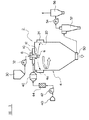
図1は本発明の一実施形態に係る噴霧乾燥システムの全体構成図、
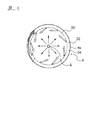
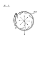
図2は図1に示す周囲吹出口からの吹出風の状態を示す概略横断面図、
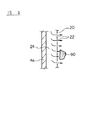
図3は図1に示す周囲吹出口の詳細を示す要部断面図、
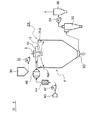
図4は本発明の他の実施形態に係る噴霧乾燥システムの全体構成図、
図5は図4に示す周囲吹出口からの吹出風の状態を示す概略横断面図、
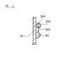
図6は図4に示す周囲吹出口の詳細を示す要部断面図である。
第1実施形態
Hereinafter, the present invention will be described based on embodiments shown in the drawings.
FIG. 1 is an overall configuration diagram of a spray drying system according to an embodiment of the present invention,
FIG. 2 is a schematic cross-sectional view showing the state of the air blowing from the surrounding air outlet shown in FIG.
FIG. 3 is a cross-sectional view of an essential part showing details of the peripheral outlet shown in FIG.
FIG. 4 is an overall configuration diagram of a spray drying system according to another embodiment of the present invention,
FIG. 5 is a schematic cross-sectional view showing a state of the blowing air from the surrounding air outlet shown in FIG.
FIG. 6 is a cross-sectional view of the main part showing details of the peripheral outlet shown in FIG.
First embodiment
図1に示すように、本発明の一実施形態に係る噴霧乾燥システムは、乾燥手段である噴霧乾燥装置2と、原液供給手段(原液タンク30、原液ポンプ32)と、熱風供給手段(エアフィルタ40、送風機42、熱風発生装置44、熱風フィルタ46)と、排気手段(サイクロン52、排風機54、集塵機56)とを有する。
As shown in FIG. 1, the spray drying system according to an embodiment of the present invention includes a
本実施形態の噴霧乾燥システムにおいては、原液供給手段(原液タンク30、原液ポンプ32)からフェライトスラリー(粉体を作るための原液)を噴霧乾燥装置2に供給し、熱風供給手段(エアフィルタ40、送風機42、熱風発生装置44、熱風フィルタ46)から送られる乾燥用熱風により、噴霧乾燥装置2内で、フェライトスラリーの乾燥を行い、顆粒状のフェライト粒を得る。
In the spray drying system of the present embodiment, ferrite slurry (raw solution for making powder) is supplied from the stock solution supply means (
噴霧乾燥装置2は、筒状の乾燥筒体4と、乾燥筒体4の上方中心部に位置する回転ディスク6とを有しており、回転ディスク6の上方にはスラリー供給部8が配置されている。このスラリー供給部8の内部には、回転ディスク6を回転させるための回転軸が配置してある。
The
このスラリー供給部8の外周には、第1熱風供給部10が筒体4の上部に形成してあり、スラリー供給部8の周囲に位置する第1熱風供給部10に設けられた上部吹出口12から、回転ディスク6に向けて第1乾燥用熱風が吹き出されるようになっている。この上部吹出口12から回転ディスク6に向けて吹き出される第1乾燥用熱風は、回転ディスク6の回転方向と同じ方向に旋回して吹き出されても、また、回転ディスクと逆方向に吹き出されても良い。その旋回の方向を調節するには、吹出口12の吹出ノズル方向を設定したり、熱風フィルタ46から分岐部を通して第1熱風供給部10へと入る空気の流れ方向を制御すればよい。
On the outer periphery of the slurry supply unit 8, a first hot air supply unit 10 is formed in the upper part of the cylinder 4, and an upper outlet provided in the first hot air supply unit 10 located around the slurry supply unit 8. 12, the first hot air for drying is blown out toward the rotating disk 6. The first hot air for drying blown from the upper outlet 12 toward the rotating disk 6 is blown in the same direction as the rotating direction of the rotating disk 6 or is blown out in the opposite direction to the rotating disk. May be. In order to adjust the direction of the swirl, the direction of the blow nozzle of the blower outlet 12 may be set, or the flow direction of the air entering the first hot air supply unit 10 from the
筒体4の上部壁には、ディスク対向部4aが形成してある。ディスク対向部4aは、乾燥筒体4において、回転ディスク6の回転平面と交差する部分を含む壁部であり、他の部分よりも外側に膨らんでいる。このディスク対向部4aは、本実施形態では、乾燥筒体4の上部に、所定の軸方向長さ範囲で形成される。 A disk facing portion 4 a is formed on the upper wall of the cylindrical body 4. The disk facing portion 4a is a wall portion including a portion that intersects the rotation plane of the rotating disk 6 in the drying cylinder 4, and swells outward from the other portions. In this embodiment, the disk facing portion 4a is formed in the upper portion of the drying cylinder 4 within a predetermined axial length range.
このディスク対向部4aには、第2熱風供給部24が形成されている。第2熱風供給部24は、熱風フィルタ46から送られる乾燥用熱風の一部を、第2乾燥用熱風として、筒体4の内部に吹き出す部分であり、多数の周囲吹出口22が全周に形成してあるリング状のパンチングプレート20を有する。このパンチングプレート20は、筒体4の内壁面と面一となるように配置される。
A second hot
パンチングプレート20の吹出口22から筒体4の内部に向けて吹き出される第2乾燥用熱風は、第1乾燥用熱風の旋回方向と同じ方向に旋回して吹き出されるようになっている。すなわち、周囲吹出口22から吹き出される熱風の旋回方向は、上部吹出口12から吹き出される熱風の旋回方向と同じである。その旋回の方向を調節する手段は、上部吹出口12から吹き出される熱風の旋回方向を調節するための手段と同様である。
The 2nd hot air for drying blown out from the
パンチングプレート20に形成される周囲吹出口22の数や、形成間隔、口径等は、特に限定されず、スラリーの性状や、スラリーの噴霧速度等に応じて適宜選択すれば良いが、通常、周囲吹出口22の形成ピッチ間隔は、5〜20mm程度、口径は1〜5mm程度である。
The number, the formation interval, the diameter and the like of the
次に、本実施形態のフェライト粒の製造方法について詳述する。
まず、フェライト材料を含有するフェライトスラリーを調整し、調整したフェライトスラリーを原液タンク30に供給する。フェライト材料は、たとえば、数種類のフェライト原料を配合し、粉砕し、仮焼きを行うことにより得ることができる。フェライトスラリー中のフェライト材料の濃度は、特に限定されないが、フェライトスラリー全体に対して、通常50〜70重量%程度である。また、原液タンク30には、必要に応じて、供給したフェライトスラリーの増粘や分離等を防止するための撹拌手段を設けても良い。
Next, the manufacturing method of the ferrite grain of this embodiment is explained in full detail.
First, a ferrite slurry containing a ferrite material is prepared, and the adjusted ferrite slurry is supplied to the
次いで、フェライトスラリーを、原液タンク30よりポンプ32を介して、噴霧乾燥装置2の上部に設けられたスラリー供給部8に供給する。スラリー供給部8へのスラリー供給速度は、ポンプ32により適宜調整可能となっている。
Next, the ferrite slurry is supplied from the
次いで、スラリー供給部8から供給されたフェライトスラリーを、噴霧乾燥装置2内で、乾燥することにより顆粒状のフェライト粒を得る。噴霧乾燥装置2においては、まず、スラリー供給部8から供給されたフェライトスラリーが、回転ディスク6上に滴下される。回転ディスク6は、スラリー供給部8から滴下されるスラリーを、遠心力により乾燥筒体4の内壁に向けて、放射状に噴霧し、スラリーを微小液滴とする。
Next, the ferrite slurry supplied from the slurry supply unit 8 is dried in the
なお、回転ディスク6の回転数は、特に限定されないが、2000〜15000rpm程度とする。 The rotational speed of the rotary disk 6 is not particularly limited, but is about 2000 to 15000 rpm.
スラリーの噴霧は、回転ディスク6の遠心力により行われるため、微小液滴は、最初に、乾燥筒体4のディスク対向部4aにおける内周壁に向けて、渦を巻きながら放射状に放出される。その後、筒体4の内部を渦巻き状に下に向けて流れて滞留し、その間に乾燥されて、乾燥されたフェライト粒が乾燥材料排出口50より排出される。
Since the spraying of the slurry is performed by the centrifugal force of the rotating disk 6, the micro droplets are first discharged radially while vortexing toward the inner peripheral wall of the disk facing portion 4 a of the drying cylinder 4. Thereafter, the inside of the cylindrical body 4 flows downward in a spiral shape and stays therein, and is dried during that time, and the dried ferrite particles are discharged from the dry
微小液滴の乾燥は、第1熱風供給部10および第2熱風供給部24から乾燥筒体4内に吹き出される第1および第2乾燥用熱風により行われる。第1熱風供給部10および第2熱風供給部24への乾燥用熱風の供給は、熱風供給手段(エアフィルタ40、送風機42、熱風発生装置44、熱風フィルタ46)により行われる。
The fine droplets are dried by the first and second hot air for drying blown out from the first hot air supply unit 10 and the second hot
熱風供給手段から噴霧乾燥装置2への乾燥用熱風の供給は、次のようにして行われる。まず、エアフィルタ40を介して、送風機42により送られた空気を熱風発生装置44に通し、乾燥用熱風を発生させる。次いで、熱風発生装置44により発生させた乾燥用熱風を、熱風フィルタ46に通し、その後に、噴霧乾燥装置2へと乾燥用熱風は送られる。
The supply of hot air for drying from the hot air supply means to the
本実施形態においては、乾燥手段から送られる乾燥用熱風は、分岐部により、乾燥筒体4の上部に位置する第1熱風供給部10と、ディスク対向部4aに形成された第2熱風供給部24とに、それぞれ分けられる。なお、第1熱風供給部10および第2熱風供給部24への乾燥用熱風の供給割合は、インバーター可変バルブ等により適宜調整可能としても良い。
In the present embodiment, the hot air for drying sent from the drying means is divided into a first hot air supply unit 10 located above the drying cylinder 4 and a second hot air supply unit formed in the disk facing portion 4a. And 24. In addition, the supply ratio of the hot air for drying to the 1st hot air supply part 10 and the 2nd hot
第1および第2乾燥用熱風の温度は、特に限定されず、スラリー中の溶媒の種類および溶媒の含有量に合わせて適宜選択すれば良いが、好ましくは、150〜400°C、より好ましくは200〜300°C程度である。第1および第2乾燥用熱風の温度が低すぎると溶媒の乾燥が不十分となり、乾燥筒体4内壁への付着物の堆積が顕著になる傾向にあり、温度が高すぎると、微小液滴の乾燥が不均一となり、良好な球形の顆粒が得られなくなる傾向にある。 The temperature of the first and second drying hot air is not particularly limited, and may be appropriately selected according to the type of solvent and the content of the solvent in the slurry, but is preferably 150 to 400 ° C, more preferably It is about 200-300 degreeC. If the temperature of the first and second hot air for drying is too low, the solvent is not sufficiently dried, and deposits tend to be noticeably deposited on the inner wall of the drying cylinder 4. As a result, drying tends to be uneven and good spherical granules tend not to be obtained.
なお、第1および第2乾燥用熱風の温度は、同じであることが好ましいが、異なっていても良い。 In addition, although it is preferable that the temperature of the 1st and 2nd hot air for drying is the same, you may differ.
また、上部吹出口12より吹き出される第1乾燥用熱風の第1風量(F1)と周囲吹出口22より吹き出される第2乾燥用熱風の第2風量(F2)との比(F1/F2)は、9/1〜1/9となるように制御することが好ましく、より好ましくは8/2〜5/5とする。第1風量(F1)と第2風量(F2)との比(F1/F2)が大きすぎると、従来技術に近づき、微小液滴による内壁への堆積物60が多くなり、本発明の効果が得られなくなる傾向にある。また、小さすぎると、微小液滴の乾燥が不均一となり、良好な球形の顆粒が得られなくなる傾向にある。
Further, the ratio (F1 / F2) between the first air volume (F1) of the first drying hot air blown from the upper outlet 12 and the second air volume (F2) of the second drying hot air blown from the peripheral outlet 22 ) Is preferably controlled to be 9/1 to 1/9, more preferably 8/2 to 5/5. If the ratio (F1 / F2) between the first air volume (F1) and the second air volume (F2) is too large, it approaches the prior art, and the
なお、噴霧乾燥装置2に送られた第1および第2乾燥用熱風は、排気手段であるサイクロン52、俳風機54およびバグフィルタ・スクラバー等の集塵機56により、噴霧乾燥により気化した溶媒や粉塵と共に回収される。
The first and second hot air for drying sent to the
微小液滴を乾燥することにより得られたフェライト粒を乾燥材料排出口50より排出し、顆粒状のフェライト粒を得る。このようにして得られたフェライト粒は、通常、所定形状に成形され、焼成されることにより、フェライト焼結体とされる。フェライト焼結体は、たとえば、所定径の導線を所定回数巻回することによりコイル用のコアや、トランス用のコアとして使用される。
The ferrite particles obtained by drying the fine droplets are discharged from the dry
本実施形態に係る噴霧乾燥装置2では、スラリーを回転ディスク6により微細粒子として飛散させ、飛行曲線端部と乾燥筒体4の内壁とが接触する部分4aに付着堆積する物質60の成長を阻害させることができる。
In the
本実施形態に係る装置2により、乾燥筒体4の内壁に付着する乾燥物60の減量が可能となり、乾燥筒体の内径を一回り小さくでき、収率改善と生産性向上が可能となる。なお、乾燥筒体4の内壁付着物60に関しては、堆積および落下の繰り返しにより、乾燥室下部の回収部分の閉塞が起こることがあった。しかしながら、本実施形態の装置2により、連続して噴霧が可能となる。
The
さらに本実施形態では、上部吹出口12より吹き出される第1乾燥用熱風と、周囲吹出口22より吹き出される第2乾燥用熱風との送風方向が同一であるために、微小液滴の乾燥筒体4内での滞留が長時間となるようアシストすることができる。その結果、乾燥効率が向上すると共に、付着物の堆積防止効果が高まり、微小液滴の乾燥を均一に行うことができ、良好な球形の顆粒とすることができる。
第2実施形態
Furthermore, in this embodiment, since the blowing direction of the 1st hot air for drying blown from the upper blower outlet 12 and the 2nd hot air for drying blown from the surrounding
Second embodiment
本実施形態の噴霧乾燥装置2Aは、第1実施形態の装置2と以下に示す以外は、同一な構成と作用を有し、その重複する説明は省略する。
The
本実施形態の噴霧乾燥装置2Aでは、第1実施形態と異なり、図4〜図6に示すように、第2熱風供給部24Aが、吹出用パイプ20Aで構成してある。このパイプ20Aは、筒体4の上部に位置するディスク対向部4a1の内周壁面に沿って周方向に配置してある。なお、このパイプ20Aの配置位置は、ディスク対向部4a1よりも若干上方でも良い。
In the
吹出用パイプ20Aは、図6に示すように、断面形状が中空となっており、この中空部には、第2乾燥用熱風を送るための第2熱風供給部24Aが形成されている。吹出用パイプ20Aの下方には、周方向に沿って所定間隔で複数の周囲吹出口22Aが形成してある。この周囲吹出口22Aから、第2乾燥用熱風が、ディスク対向部4a1の内周壁面に沿って下方に吹き出される。
As shown in FIG. 6, the blowing
吹出用パイプ20Aに形成される周囲吹出口22Aの数や、形成間隔、口径等は、特に限定されないが、通常、周囲吹出口22の形成ピッチ間隔は、5〜20mm程度、口径は1〜5mm程度である。
The number, the formation interval, the diameter, and the like of the
周囲吹出口22Aから吹き出される乾燥用熱風の送風方向は、上述の実施形態と同様に、図5に示すように、旋回流を形成するようにすることが好ましく、より好ましくは、上部吹出口12より吹き出される乾燥用熱風の送風方向と同一とする。
As in the above-described embodiment, the blowing direction of the hot air for drying blown from the surrounding
また、吹出用パイプ20Aは、微小液滴が噴霧される方向に応じて、乾燥筒体4の内壁に沿って上下方向に移動自在とすることも可能である。また、図4〜図6に示す噴霧乾燥装置2Aでは、1個の吹出用パイプ20Aを有する構造としたが、必要に応じて、複数個の吹出用パイプ20Aを形成することも可能である。
その他の実施形態
Further, the blowing
Other embodiments
なお、本発明は、上述した実施形態に限定されるものではなく、本発明の範囲内で種々に改変することができる。
たとえば、上述した第1実施形態では、周囲吹出口22を形成するための多孔部材として、パンチングプレート20を使用したが、周囲吹出口22を形成可能な多孔部材であれば特に限定されず、たとえば多孔質金属等を使用することも可能である。
The present invention is not limited to the above-described embodiment, and can be variously modified within the scope of the present invention.
For example, in the first embodiment described above, the punching
以下、本発明を、さらに詳細な実施例に基づき説明するが、本発明は、これら実施例に限定されない。
実施例1
Hereinafter, although this invention is demonstrated based on a more detailed Example, this invention is not limited to these Examples.
Example 1
まず、出発原料として、フェライト原料を用意し、フェライト原料と純水とを撹拌・混合し、次いで、配合粉砕機を使用して配合・粉砕を行い、フェライトスラリーを作製した。本実施例においては、フェライトスラリー中のフェライト原料の含有量は、フェライトスラリー全体に対して、67重量%となるように調整した。 First, a ferrite raw material was prepared as a starting raw material, the ferrite raw material and pure water were stirred and mixed, and then blended and pulverized using a compounding pulverizer to prepare a ferrite slurry. In this example, the content of the ferrite raw material in the ferrite slurry was adjusted to 67% by weight with respect to the entire ferrite slurry.
次いで、得られたフェライトスラリーについて、図1〜3に示す周囲吹出口22を持つ噴霧乾燥装置2を使用して、噴霧乾燥を行った。噴霧乾燥の条件としては、回転ディスク6の回転数を5000rpm、第1および第2乾燥用熱風の温度を共に250℃とした。
Next, the obtained ferrite slurry was spray-dried using the spray-drying
噴霧乾燥の結果、乾燥筒体4への付着物60の堆積、および乾燥状態のフェライト粒による乾燥材料排出口50の閉塞の発生は認められず、良好に連続運転を行うことができた。
As a result of the spray drying, no
また、本実施例においては、フェライトスラリー中のフェライト原料の含有量を、フェライトスラリー全体に対して、70重量%としたスラリーを使用した場合、あるいは、回転ディスク6の回転数を8000rpm、13000rpmとした場合にも同様の結果となった。
比較例1
In this example, the ferrite raw material content in the ferrite slurry is 70% by weight with respect to the entire ferrite slurry, or the rotational speed of the rotating disk 6 is 8000 rpm and 13000 rpm. Similar results were obtained.
Comparative Example 1
第2乾燥用熱風を送り込むための周囲吹出口22または22Aを有しない従来の噴霧乾燥装置を使用した以外は、実施例1と同様にして噴霧乾燥を行った。
Spray drying was performed in the same manner as in Example 1 except that a conventional spray drying apparatus having no surrounding
噴霧乾燥の結果、乾燥筒体に、付着物の堆積が発生し、この堆積が原因となりフェライト粒の凝集が発生し、凝集したフェライト粒の影響により乾燥材料排出口50が閉塞してしまい、連続運転を行うことができなかった。
As a result of the spray drying, deposits are deposited on the dried cylinder, and the accumulation of ferrite particles is caused by the accumulation, and the dry
また、フェライトスラリー中のフェライト原料の濃度を70重量%とした場合、および回転ディスク6の回転数を8000rpm、13000rpmとした場合にも同様の結果となった。 The same results were obtained when the concentration of the ferrite raw material in the ferrite slurry was 70% by weight and when the rotational speed of the rotating disk 6 was 8000 rpm and 13000 rpm.
この結果より、回転ディスクを使用する噴霧乾燥装置において、乾燥用熱風が吹き出される周囲吹出口を、乾燥筒体の内壁の全周に沿って具備することにより、乾燥筒体への付着物の堆積、および乾燥状態のフェライト粒による乾燥材料排出口の閉塞を有効に防止することができることが確認できた。 From this result, in the spray drying apparatus using a rotating disk, by providing a peripheral outlet along which the hot air for drying is blown out along the entire circumference of the inner wall of the drying cylinder, It was confirmed that clogging of the dry material outlet due to accumulation and dry ferrite grains can be effectively prevented.
2,2A… 噴霧乾燥装置
4… 乾燥筒体
4a,4a1… ディスク対向部
6… 回転ディスク
8… スラリー供給部
10… 第1熱風供給部
12… 上部吹出口
20… パンチングプレート
20A… 吹出用パイプ
22,22A… 周囲吹出口
24,24A… 第2熱風供給部
30… 原液タンク
32… 原液ポンプ
40… エアフィルタ
42… 送風機
44… 熱風発生装置
46… 熱風フィルタ
50… 乾燥材料排出口
52… サイクロン
54… 排風機
56… 集塵機
60… 付着物
DESCRIPTION OF
Claims (11)
前記微小液滴が放射状に噴霧される前記乾燥筒体の内壁には、前記乾燥用熱風の少なくとも一部が吹き出される周囲吹出口が、前記乾燥筒体の内壁の全周に沿って具備してあることを特徴とする噴霧乾燥装置。 The stock solution for making the powder is sprayed radially from the rotating disk provided at the upper central portion of the drying cylinder toward the inner wall of the drying cylinder so as to be a fine droplet, and the sprayed micro In a spray-drying apparatus for drying droplets with hot air for drying and immediately producing powder from the stock solution,
The inner wall of the drying cylinder to which the microdroplets are sprayed radially is provided with a peripheral air outlet through which at least a part of the hot air for drying is blown out along the entire circumference of the inner wall of the drying cylinder. A spray-drying device characterized by that.
The manufacturing method of the ferrite grain which manufactures a ferrite grain using the spray-drying apparatus in any one of Claims 1-9.
Priority Applications (1)
| Application Number | Priority Date | Filing Date | Title |
|---|---|---|---|
| JP2004103182A JP2005291530A (en) | 2004-03-31 | 2004-03-31 | Spray drying device, powder drying method, and method of manufacturing ferrite particle |
Applications Claiming Priority (1)
| Application Number | Priority Date | Filing Date | Title |
|---|---|---|---|
| JP2004103182A JP2005291530A (en) | 2004-03-31 | 2004-03-31 | Spray drying device, powder drying method, and method of manufacturing ferrite particle |
Publications (1)
| Publication Number | Publication Date |
|---|---|
| JP2005291530A true JP2005291530A (en) | 2005-10-20 |
Family
ID=35324658
Family Applications (1)
| Application Number | Title | Priority Date | Filing Date |
|---|---|---|---|
| JP2004103182A Withdrawn JP2005291530A (en) | 2004-03-31 | 2004-03-31 | Spray drying device, powder drying method, and method of manufacturing ferrite particle |
Country Status (1)
| Country | Link |
|---|---|
| JP (1) | JP2005291530A (en) |
Cited By (23)
| Publication number | Priority date | Publication date | Assignee | Title |
|---|---|---|---|---|
| JP2010008447A (en) * | 2008-06-24 | 2010-01-14 | Ricoh Co Ltd | Method producing toner and apparatus for producing toner |
| JP2010099586A (en) * | 2008-10-23 | 2010-05-06 | National Institute For Materials Science | Apparatus and method for producing solid particle |
| WO2012157334A1 (en) * | 2011-05-16 | 2012-11-22 | 株式会社東芝 | Method for producing molybdenum granulated powder, and molybdenum granulated powder |
| WO2012157336A1 (en) * | 2011-05-19 | 2012-11-22 | 株式会社東芝 | Method for producing molybdenum granulated powder, and molybdenum granulated powder |
| WO2012169256A1 (en) * | 2011-06-08 | 2012-12-13 | 株式会社東芝 | Method for producing molybdenum granulated powder and molybdenum granulated powder |
| WO2012169258A1 (en) * | 2011-06-08 | 2012-12-13 | 株式会社東芝 | Method for producing molybdenum granulated powder and molybdenum granulated powder |
| WO2012169261A1 (en) * | 2011-06-08 | 2012-12-13 | 株式会社東芝 | Method for producing molybdenum granulated powder and molybdenum granulated powder |
| WO2012169255A1 (en) * | 2011-06-08 | 2012-12-13 | 株式会社東芝 | Method for producing molybdenum granulated powder and molybdenum granulated powder |
| WO2012169262A1 (en) * | 2011-06-08 | 2012-12-13 | 株式会社東芝 | Method for producing molybdenum granulated powder and molybdenum granulated powder |
| US8748072B2 (en) | 2008-06-23 | 2014-06-10 | Ricoh Company, Ltd. | Method and apparatus for producing toner |
| CN106730948A (en) * | 2016-12-15 | 2017-05-31 | 河海大学常州校区 | A kind of anti-material of centrifugal spray dryer glues wall device |
| JP2018071839A (en) * | 2016-10-26 | 2018-05-10 | 東京電力ホールディングス株式会社 | Particle generator |
| CN108534531A (en) * | 2018-05-16 | 2018-09-14 | 长沙中瓷新材料科技有限公司 | A kind of spray drying system |
| JP2019025394A (en) * | 2017-07-27 | 2019-02-21 | 太平洋セメント株式会社 | Production method of fine particles |
| CN109442958A (en) * | 2018-12-04 | 2019-03-08 | 什邡市志信化工有限公司 | A kind of atomizing dry tower of the heat sensitive material of double funnel structures |
| CN113521784A (en) * | 2021-07-05 | 2021-10-22 | 内蒙古工业大学 | A micro-distillation heat integrated system |
| CN113663347A (en) * | 2021-08-21 | 2021-11-19 | 叶丽珊 | Variable speed centrifugal spray drying equipment |
| CN114712873A (en) * | 2022-06-09 | 2022-07-08 | 山东颐工材料科技股份有限公司 | ACR spray drying tower drying device |
| CN115654843A (en) * | 2022-12-09 | 2023-01-31 | 蓬莱市绿源有机复合肥有限公司 | Effect a long time high concentration compression fertilizer apparatus for producing |
| CN116370984A (en) * | 2023-04-21 | 2023-07-04 | 安徽凤阳赛吉元无机材料有限公司 | A kind of anti-agglomeration spray drying device and process of micronano white carbon black |
| CN118807230A (en) * | 2024-09-18 | 2024-10-22 | 江苏鑫普干燥工程科技有限公司 | A kind of ultra-fine material uniform spray drying equipment |
| CN119303323A (en) * | 2024-12-12 | 2025-01-14 | 内蒙古华利科技发展有限公司 | A spray dryer and drying method for maple leaf extract |
| CN120132371A (en) * | 2025-05-14 | 2025-06-13 | 山东绿陇生物科技有限公司 | A multifunctional bioactive chicken blood peptide preparation device |
-
2004
- 2004-03-31 JP JP2004103182A patent/JP2005291530A/en not_active Withdrawn
Cited By (31)
| Publication number | Priority date | Publication date | Assignee | Title |
|---|---|---|---|---|
| US8748072B2 (en) | 2008-06-23 | 2014-06-10 | Ricoh Company, Ltd. | Method and apparatus for producing toner |
| JP2010008447A (en) * | 2008-06-24 | 2010-01-14 | Ricoh Co Ltd | Method producing toner and apparatus for producing toner |
| JP2010099586A (en) * | 2008-10-23 | 2010-05-06 | National Institute For Materials Science | Apparatus and method for producing solid particle |
| WO2012157334A1 (en) * | 2011-05-16 | 2012-11-22 | 株式会社東芝 | Method for producing molybdenum granulated powder, and molybdenum granulated powder |
| CN103442829A (en) * | 2011-05-19 | 2013-12-11 | 株式会社东芝 | Method for producing molybdenum granulated powder, and molybdenum granulated powder |
| WO2012157336A1 (en) * | 2011-05-19 | 2012-11-22 | 株式会社東芝 | Method for producing molybdenum granulated powder, and molybdenum granulated powder |
| CN103442829B (en) * | 2011-05-19 | 2016-11-16 | 株式会社东芝 | The manufacture method of molybdenum pelletizing and molybdenum pelletizing |
| WO2012169261A1 (en) * | 2011-06-08 | 2012-12-13 | 株式会社東芝 | Method for producing molybdenum granulated powder and molybdenum granulated powder |
| WO2012169255A1 (en) * | 2011-06-08 | 2012-12-13 | 株式会社東芝 | Method for producing molybdenum granulated powder and molybdenum granulated powder |
| WO2012169262A1 (en) * | 2011-06-08 | 2012-12-13 | 株式会社東芝 | Method for producing molybdenum granulated powder and molybdenum granulated powder |
| WO2012169257A1 (en) * | 2011-06-08 | 2012-12-13 | 株式会社東芝 | Method for producing molybdenum granulated powder and molybdenum granulated powder |
| WO2012169258A1 (en) * | 2011-06-08 | 2012-12-13 | 株式会社東芝 | Method for producing molybdenum granulated powder and molybdenum granulated powder |
| WO2012169256A1 (en) * | 2011-06-08 | 2012-12-13 | 株式会社東芝 | Method for producing molybdenum granulated powder and molybdenum granulated powder |
| JP2018071839A (en) * | 2016-10-26 | 2018-05-10 | 東京電力ホールディングス株式会社 | Particle generator |
| CN106730948A (en) * | 2016-12-15 | 2017-05-31 | 河海大学常州校区 | A kind of anti-material of centrifugal spray dryer glues wall device |
| JP7046518B2 (en) | 2017-07-27 | 2022-04-04 | 太平洋セメント株式会社 | Manufacturing method of fine particles |
| JP2019025394A (en) * | 2017-07-27 | 2019-02-21 | 太平洋セメント株式会社 | Production method of fine particles |
| CN108534531A (en) * | 2018-05-16 | 2018-09-14 | 长沙中瓷新材料科技有限公司 | A kind of spray drying system |
| CN108534531B (en) * | 2018-05-16 | 2024-04-26 | 长沙中瓷新材料科技有限公司 | A spray drying system |
| CN109442958A (en) * | 2018-12-04 | 2019-03-08 | 什邡市志信化工有限公司 | A kind of atomizing dry tower of the heat sensitive material of double funnel structures |
| CN113521784A (en) * | 2021-07-05 | 2021-10-22 | 内蒙古工业大学 | A micro-distillation heat integrated system |
| CN113521784B (en) * | 2021-07-05 | 2023-01-06 | 内蒙古工业大学 | Micro-rectification heat integration system |
| CN113663347A (en) * | 2021-08-21 | 2021-11-19 | 叶丽珊 | Variable speed centrifugal spray drying equipment |
| CN114712873A (en) * | 2022-06-09 | 2022-07-08 | 山东颐工材料科技股份有限公司 | ACR spray drying tower drying device |
| CN115654843A (en) * | 2022-12-09 | 2023-01-31 | 蓬莱市绿源有机复合肥有限公司 | Effect a long time high concentration compression fertilizer apparatus for producing |
| CN115654843B (en) * | 2022-12-09 | 2023-03-10 | 蓬莱市绿源有机复合肥有限公司 | Device for producing long-acting high-concentration compressed organic fertilizer |
| CN116370984A (en) * | 2023-04-21 | 2023-07-04 | 安徽凤阳赛吉元无机材料有限公司 | A kind of anti-agglomeration spray drying device and process of micronano white carbon black |
| CN118807230A (en) * | 2024-09-18 | 2024-10-22 | 江苏鑫普干燥工程科技有限公司 | A kind of ultra-fine material uniform spray drying equipment |
| CN119303323A (en) * | 2024-12-12 | 2025-01-14 | 内蒙古华利科技发展有限公司 | A spray dryer and drying method for maple leaf extract |
| CN120132371A (en) * | 2025-05-14 | 2025-06-13 | 山东绿陇生物科技有限公司 | A multifunctional bioactive chicken blood peptide preparation device |
| CN120132371B (en) * | 2025-05-14 | 2025-08-05 | 山东绿陇生物科技有限公司 | A multifunctional bioactive chicken blood peptide preparation equipment |
Similar Documents
| Publication | Publication Date | Title |
|---|---|---|
| JP2005291530A (en) | Spray drying device, powder drying method, and method of manufacturing ferrite particle | |
| JP3585654B2 (en) | Two-stage drying spray dryer | |
| CN103347616B (en) | External mix formula pressurization two-fluid spray nozzle and spray drying process | |
| JP2010510054A (en) | Method and apparatus for producing and / or conditioning a powdered material | |
| RU2347166C1 (en) | Fluidised bed dryer with inert nozzle | |
| WO2003000397A1 (en) | Powder particle processing device | |
| JPH0727476A (en) | Treatment apparatus of moistened granular material | |
| EP2561935B1 (en) | Method for classifying powder | |
| KR20080101559A (en) | Rotary spray drying apparatus and drying chamber having the same | |
| CN206897343U (en) | A kind of low tower spray-cooling granulating device | |
| JP2023041617A (en) | Apparatus and method for manufacturing granulation sintering raw material | |
| JP2004122057A (en) | Fluidized bed equipment | |
| RU2326303C1 (en) | Spray dryer | |
| RU2328668C1 (en) | Plant of zeolite drying and tempering | |
| JP2011033269A (en) | Spray dryer and method of manufacturing granule | |
| RU2326302C1 (en) | Fluidised-bed dryer with passive nozzle | |
| RU2340850C1 (en) | Boiling bed dryer with passive nozzle | |
| JPH09103668A (en) | Powder processing equipment | |
| JP5299134B2 (en) | Spray drying apparatus and method for producing granules | |
| CN208936724U (en) | Spray drying tower | |
| CN109289697B (en) | Spraying-starch bed granulation equipment | |
| JPH0411252B2 (en) | ||
| RU2341740C1 (en) | Drying unit with inert head | |
| RU223751U1 (en) | SPRAY DRYER | |
| JP2011033268A (en) | Spray dryer and method of manufacturing granule |
Legal Events
| Date | Code | Title | Description |
|---|---|---|---|
| A300 | Withdrawal of application because of no request for examination |
Free format text: JAPANESE INTERMEDIATE CODE: A300 Effective date: 20070605 |