JP2005291512A - Stove - Google Patents
Stove Download PDFInfo
- Publication number
- JP2005291512A JP2005291512A JP2004102483A JP2004102483A JP2005291512A JP 2005291512 A JP2005291512 A JP 2005291512A JP 2004102483 A JP2004102483 A JP 2004102483A JP 2004102483 A JP2004102483 A JP 2004102483A JP 2005291512 A JP2005291512 A JP 2005291512A
- Authority
- JP
- Japan
- Prior art keywords
- state
- switch
- heating
- burner
- detection state
- Prior art date
- Legal status (The legal status is an assumption and is not a legal conclusion. Google has not performed a legal analysis and makes no representation as to the accuracy of the status listed.)
- Pending
Links
Images


Classifications
-
- B—PERFORMING OPERATIONS; TRANSPORTING
- B09—DISPOSAL OF SOLID WASTE; RECLAMATION OF CONTAMINATED SOIL
- B09B—DISPOSAL OF SOLID WASTE NOT OTHERWISE PROVIDED FOR
- B09B3/00—Destroying solid waste or transforming solid waste into something useful or harmless
-
- B—PERFORMING OPERATIONS; TRANSPORTING
- B01—PHYSICAL OR CHEMICAL PROCESSES OR APPARATUS IN GENERAL
- B01F—MIXING, e.g. DISSOLVING, EMULSIFYING OR DISPERSING
- B01F35/00—Accessories for mixers; Auxiliary operations or auxiliary devices; Parts or details of general application
- B01F35/30—Driving arrangements; Transmissions; Couplings; Brakes
- B01F35/32—Driving arrangements
- B01F35/32005—Type of drive
- B01F35/3204—Motor driven, i.e. by means of an electric or IC motor
-
- B—PERFORMING OPERATIONS; TRANSPORTING
- B09—DISPOSAL OF SOLID WASTE; RECLAMATION OF CONTAMINATED SOIL
- B09B—DISPOSAL OF SOLID WASTE NOT OTHERWISE PROVIDED FOR
- B09B3/00—Destroying solid waste or transforming solid waste into something useful or harmless
- B09B3/40—Destroying solid waste or transforming solid waste into something useful or harmless involving thermal treatment, e.g. evaporation
-
- F—MECHANICAL ENGINEERING; LIGHTING; HEATING; WEAPONS; BLASTING
- F26—DRYING
- F26B—DRYING SOLID MATERIALS OR OBJECTS BY REMOVING LIQUID THEREFROM
- F26B21/00—Arrangements for supplying or controlling air or other gases for drying solid materials or objects
- F26B21/20—Circulating air or gases in closed cycles, e.g. wholly within the drying enclosure
- F26B21/202—Circulating air or gases in closed cycles, e.g. wholly within the drying enclosure with means for changing the flow pattern, e.g. by reversing gas flow or by moving the materials or objects through subsequent compartments, at least two of which have a different flow direction
- F26B21/204—Circulating air or gases in closed cycles, e.g. wholly within the drying enclosure with means for changing the flow pattern, e.g. by reversing gas flow or by moving the materials or objects through subsequent compartments, at least two of which have a different flow direction by using movable fan units
-
- F—MECHANICAL ENGINEERING; LIGHTING; HEATING; WEAPONS; BLASTING
- F26—DRYING
- F26B—DRYING SOLID MATERIALS OR OBJECTS BY REMOVING LIQUID THEREFROM
- F26B21/00—Arrangements for supplying or controlling air or other gases for drying solid materials or objects
- F26B21/30—Controlling, e.g. regulating, parameters of gas supply
- F26B21/33—Humidity
- F26B21/333—Humidity by condensing the moisture in the drying medium, which may be recycled, e.g. using a heat pump cycle
-
- F—MECHANICAL ENGINEERING; LIGHTING; HEATING; WEAPONS; BLASTING
- F26—DRYING
- F26B—DRYING SOLID MATERIALS OR OBJECTS BY REMOVING LIQUID THEREFROM
- F26B3/00—Drying solid materials or objects by processes involving the application of heat
- F26B3/02—Drying solid materials or objects by processes involving the application of heat by convection, i.e. heat being conveyed from a heat source to the materials or objects to be dried by a gas or vapour, e.g. air
-
- B—PERFORMING OPERATIONS; TRANSPORTING
- B01—PHYSICAL OR CHEMICAL PROCESSES OR APPARATUS IN GENERAL
- B01F—MIXING, e.g. DISSOLVING, EMULSIFYING OR DISPERSING
- B01F2101/00—Mixing characterised by the nature of the mixed materials or by the application field
- B01F2101/25—Mixing waste with other ingredients
-
- B—PERFORMING OPERATIONS; TRANSPORTING
- B09—DISPOSAL OF SOLID WASTE; RECLAMATION OF CONTAMINATED SOIL
- B09B—DISPOSAL OF SOLID WASTE NOT OTHERWISE PROVIDED FOR
- B09B2101/00—Type of solid waste
- B09B2101/02—Gases or liquids enclosed in discarded articles, e.g. aerosol cans or cooling systems of refrigerators
-
- F—MECHANICAL ENGINEERING; LIGHTING; HEATING; WEAPONS; BLASTING
- F26—DRYING
- F26B—DRYING SOLID MATERIALS OR OBJECTS BY REMOVING LIQUID THEREFROM
- F26B2200/00—Drying processes and machines for solid materials characterised by the specific requirements of the drying goods
- F26B2200/04—Garbage
-
- Y—GENERAL TAGGING OF NEW TECHNOLOGICAL DEVELOPMENTS; GENERAL TAGGING OF CROSS-SECTIONAL TECHNOLOGIES SPANNING OVER SEVERAL SECTIONS OF THE IPC; TECHNICAL SUBJECTS COVERED BY FORMER USPC CROSS-REFERENCE ART COLLECTIONS [XRACs] AND DIGESTS
- Y02—TECHNOLOGIES OR APPLICATIONS FOR MITIGATION OR ADAPTATION AGAINST CLIMATE CHANGE
- Y02W—CLIMATE CHANGE MITIGATION TECHNOLOGIES RELATED TO WASTEWATER TREATMENT OR WASTE MANAGEMENT
- Y02W30/00—Technologies for solid waste management
- Y02W30/20—Waste processing or separation
Landscapes
- Engineering & Computer Science (AREA)
- Mechanical Engineering (AREA)
- General Engineering & Computer Science (AREA)
- Environmental & Geological Engineering (AREA)
- Life Sciences & Earth Sciences (AREA)
- Microbiology (AREA)
- Chemical & Material Sciences (AREA)
- Chemical Kinetics & Catalysis (AREA)
- Physics & Mathematics (AREA)
- Thermal Sciences (AREA)
- Electric Stoves And Ranges (AREA)
Abstract
【課題】使用者の操作以外の要因でタッチスイッチが非検知状態から検知状態に切り換わったときに、バーナの点火処理がなされることを防止したコンロを提供する。
【解決手段】バーナ4a,4bを収容したコンロ本体1の上面を覆うガラス天板2に、使用者がバーナ4a,4bの作動開始と停止を指示するために設けられて、ガラス天板2の上面への接触物又は接近物を検知するタッチスイッチを有する操作部6と、タッチスイッチがon状態(検知状態)であるかoff状態(非検知状態)であるかを把握し、把握結果に応じてバーナ4a,4bの作動を制御する加熱制御手段とを備えたコンロにおいて、該加熱制御手段は、バーナ4a,4bが燃焼停止状態であって、タッチスイッチがoff状態からon状態に切り換わった後にoff状態に復帰したときに、バーナ4a,4bの点火処理を行い、バーナ4a,4bが燃焼状態であって、タッチスイッチがoff状態からon状態に切り換わったときに、バーナ4a,4bの消火処理を行う。
【選択図】 図1A stove that prevents a burner from being ignited when a touch switch is switched from a non-detection state to a detection state due to a factor other than a user's operation.
A glass top plate 2 that covers the upper surface of a stove body 1 that accommodates burners 4a and 4b is provided for a user to instruct the start and stop of operation of the burners 4a and 4b. The operation unit 6 having a touch switch that detects a contact object or an approaching object to the upper surface, and whether the touch switch is in an on state (detection state) or an off state (non-detection state), and according to the grasp result And a heating control means for controlling the operation of the burners 4a and 4b. The heating control means is such that the burners 4a and 4b are in a combustion stopped state, and the touch switch is switched from the off state to the on state. When the burner 4a, 4b is ignited later when the off state is restored, the burner 4a, 4b is in the combustion state, and the touch switch is switched from the off state to the on state. To performs the burner 4a, the extinguishment process of 4b.
[Selection] Figure 1
Description
本発明は、加熱手段を備えたコンロに関し、特に天板の上面に加熱手段の作動を指示するための操作部を備えたコンロに関する。 The present invention relates to a stove provided with heating means, and more particularly to a stove provided with an operation unit for instructing the operation of the heating means on the top surface of the top plate.
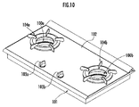
従来より、図10に示したように、システムキッチンのカウンタトップに用意された開口にコンロ本体101を埋設するドロップイン式のコンロにおいて、ガスバーナ100a,100bが収容されるコンロ本体101の上面を覆うガラス天板102に、ガスバーナ100a,100bの点火/消火と火力調節を行うための操作つまみ103a,103bを設けたものが知られている(例えば特許文献1参照)。
Conventionally, as shown in FIG. 10, in a drop-in type stove in which a
かかるコンロによれば、前面に操作部を備えたコンロを設置する場合のように、カウンタトップの前面に操作部を臨ませる開口を設ける必要がなく、カウンタトップへのコンロの設置も容易に行うことができる。また、ガスバーナの点火/消火や火力調節を天板102に設けられて視認性が良い操作つまみ103a,103bにより行うことができるため、使用者の操作性が向上する。
しかし、図10に示したコンロによれば、操作つまみ103a,103bがガラス天板102の上面に突出して配置されているため、調理を行う際に邪魔になる場合がある。そこで、ガスバーナ100a,100bの操作手段として、例えば、静電容量式のセンサの検出部をガラス天板102の裏面に設けてガラス天板102の表面に操作部を備えたタッチスイッチを構成し、ガラス天板102の上面をフラットにすることが考えられる。
However, according to the stove shown in FIG. 10, the
しかし、このようにタッチスイッチを設けた場合、五徳104a,104bに載置したなべ等からの調理物の煮こぼれやガラス天板102への落下物等によりタッチスイッチが覆われて、タッチスイッチがONすることが考えられる。そして、これにより、例えば右バーナ100bのみを用いて加熱調理を行っているときに、右バーナ100bの五徳104bに載置されたなべからの煮こぼれにより左バーナ100aの点火スイッチがONし、左バーナ100aが点火されてしまうという不都合がある。
However, when the touch switch is provided in this way, the touch switch is covered by the spilled food from the pan placed on the
そこで、本発明はかかる不都合を解消し、使用者の操作以外の要因でタッチスイッチが非検知状態から検知状態に切り換わったときに、バーナの点火処理がなされることを防止したコンロを提供することを目的とする。 Therefore, the present invention provides a stove that eliminates such inconvenience and prevents the burner from being ignited when the touch switch is switched from the non-detection state to the detection state due to a factor other than the user's operation. For the purpose.
本発明は上記目的を達成するためになされたものであり、加熱手段を収容するコンロ本体の上面を覆う天板に、使用者が該加熱手段の作動開始と停止を指示するために設けられて、該天板の上面への接触物又は接近物を検知するタッチスイッチと、該タッチスイッチが検知状態にあるか非検知状態にあるかを把握し、把握結果に応じて前記加熱手段の作動を制御する加熱制御手段とを備えたコンロの改良に関する。 The present invention has been made to achieve the above object, and is provided on a top plate covering the upper surface of a stove main body that accommodates the heating means so that the user can instruct the start and stop of the operation of the heating means. A touch switch for detecting a contact object or an approaching object to the top surface of the top plate, and whether the touch switch is in a detection state or a non-detection state, and the operation of the heating unit is performed according to the determination result. The present invention relates to improvement of a stove including heating control means for controlling.
そして、前記加熱制御手段は、前記加熱手段が停止状態にあるときに、前記タッチスイッチが非検知状態から検知状態に切り換わり、さらに非検知状態に復帰したときには、前記加熱手段の作動を開始し、前記加熱手段が作動状態にあるときに、前記タッチスイッチが非検知状態から検知状態に切り換わったときには、前記加熱手段の作動を停止することを特徴とする。 The heating control means starts the operation of the heating means when the touch switch is switched from the non-detection state to the detection state when the heating means is in a stopped state, and further returns to the non-detection state. When the touch switch is switched from the non-detection state to the detection state when the heating unit is in an operating state, the operation of the heating unit is stopped.
かかる本発明によれば、前記加熱制御手段は、前記タッチスイッチが非検知状態から検知状態に切り換わり、さらに非検知状態に復帰したときに、前記加熱手段の作動を開始する。そのため、天板上に調理物の煮こぼれや落下物(布巾等)が落ちてタッチスイッチを覆い、タッチスイッチが検知状態となっても、タッチスイッチは非検知状態に復帰していないので、加熱制御手段により加熱手段の作動が開始されることがない。 According to the present invention, the heating control unit starts the operation of the heating unit when the touch switch is switched from the non-detection state to the detection state and further returned to the non-detection state. For this reason, boiled food or fallen objects (clothes, etc.) fall on the top plate and cover the touch switch. Even if the touch switch is in the detection state, the touch switch has not returned to the non-detection state. The operation of the heating means is not started by the control means.
さらに、前記加熱手段が作動状態にあるときには、前記加熱制御手段は、前記タッチスイッチが非検知状態から検知状態に切り換わったときに、前記加熱手段の作動を停止する。そのため、使用者は、前記加熱手段の作動開始操作においては、指で前記タッチスイッチに触れた後に指をタッチスイッチから離す必要があるが、加熱手段の停止操作においては、指でタッチスイッチに触れるだけで直ちに加熱手段の作動を停止することができ、使い勝手が良い。 Further, when the heating unit is in an operating state, the heating control unit stops the operation of the heating unit when the touch switch is switched from the non-detection state to the detection state. Therefore, the user needs to release the finger from the touch switch after touching the touch switch with the finger in the operation start operation of the heating means, but touches the touch switch with the finger in the stop operation of the heating means. The operation of the heating means can be stopped immediately by simply, and it is easy to use.
また、前記タッチスイッチを複数個備え、前記加熱制御手段は、前記加熱手段が停止状態にあるときに、複数個のタッチスイッチのうちの予め設定された少なくとも2個のタッチスイッチが、予め設定された順番で、非検知状態から検知状態に切り換わってさらに非検知状態に復帰したときに、前記加熱手段の作動を開始することを特徴とする。 A plurality of touch switches, and the heating control unit is configured to set at least two preset touch switches among the plurality of touch switches when the heating unit is in a stopped state. In this order, when the non-detection state is switched to the detection state and the state is further returned to the non-detection state, the operation of the heating means is started.
かかる本発明によれば、前記加熱制御手段は、予め設定された複数個のタッチスイッチが、予め設定された順序で、非検知状態から検知状態に切り換わり、さらに非検知状態に復帰したときに、前記加熱手段の作動を開始する。そして、煮こぼれや落下物により、前記順序で複数のタッチスイッチが検知状態から非検知状態に切り換わり、さらに検知状態に復帰する可能性は極めて低いものとなると想定される。したがって、本発明によれば、煮こぼれや落下物によるタッチスイッチの誤検知により、加熱手段が作動することをさらに抑制することができる。 According to the present invention, when the plurality of preset touch switches are switched from the non-detection state to the detection state in a preset order, and further returned to the non-detection state. The operation of the heating means is started. Then, it is assumed that the possibility that the plurality of touch switches are switched from the detection state to the non-detection state in the order described above due to spilled or fallen objects and further returned to the detection state is extremely low. Therefore, according to this invention, it can further suppress that a heating means act | operates by the misdetection of the touch switch by a spill or falling object.
また、前記加熱制御手段は、前記加熱手段が作動状態にあるときに、前記予め設定された少なくとも2個のタッチスイッチのうちのいずれかが非検知状態から検知状態に切り換わったときに、前記加熱手段の作動を停止することを特徴とする。 Further, the heating control means is configured such that, when the heating means is in an operating state, when any of the preset at least two touch switches is switched from a non-detection state to a detection state, The operation of the heating means is stopped.
かかる本発明によれば、前記加熱手段が作動状態にあるときは、前記加熱手段の作動の開始指示において、前記予め設定された全てのタッチスイッチについて、検知状態から非検知状態に切り換わったことが前記加熱制御手段により把握されていることになる。そのため、前記予め選択された全てのタッチスイッチは、非検知状態から検知状態への切り換えが不能な故障状態ではなかったことになる。 According to the present invention, when the heating means is in an operating state, all the preset touch switches are switched from the detection state to the non-detection state in the instruction to start the operation of the heating means. Is grasped by the heating control means. Therefore, all the preselected touch switches are not in a failure state in which switching from the non-detection state to the detection state is impossible.
そこで、前記予め選択されたタッチスイッチのうちのいずれかが非検知状態から検知状態に切り換わったときに、前記加熱手段の作動を停止することにより、タッチスイッチの故障により前記加熱手段の作動を停止ができない状況となる可能性を低くすることができる。 Therefore, when any of the preselected touch switches is switched from the non-detection state to the detection state, the operation of the heating unit is stopped due to the failure of the touch switch by stopping the operation of the heating unit. It is possible to reduce the possibility of a situation where the vehicle cannot be stopped.
また、前記天板に、前記加熱手段が作動中であることを使用者に報知するために設けられた点灯手段と、前記加熱手段が停止状態にあるときに、前記タッチスイッチが非検知状態から検知状態に切り換わったときには、前記加熱制御手段による前記加熱手段の作動開始に先行して、前記点灯手段を点灯させる点灯制御手段とを備えたことを特徴とする。 In addition, when the heating means is in a stopped state, the lighting switch provided on the top plate for notifying the user that the heating means is in operation, and the touch switch from the non-detection state. And a lighting control means for lighting the lighting means prior to the start of the operation of the heating means by the heating control means when switched to the detection state.
かかる本発明によれば、使用者が指で前記タッチスイッチに触れて前記加熱手段の作動開始を指示したときに、実際に前記加熱制御手段によって前記加熱手段の作動が開始されるのは、使用者が前記タッチスイッチから指を離したときである。そのため、使用者が前記タッチスイッチに指を触れて離すタイミングが長いときには、タッチスイッチに触れたにもかかわらず状況が何も変わらず、使用者に違和感を与えてしまうおそれがある。 According to the present invention, when the user touches the touch switch with a finger and instructs to start the operation of the heating unit, the operation of the heating unit is actually started by the heating control unit. This is when a person lifts his finger from the touch switch. Therefore, when the timing when the user touches and releases the touch switch is long, the situation does not change even though the user touches the touch switch, and the user may feel uncomfortable.
そこで、前記点灯制御手段により、前記タッチスイッチが非検知状態から検知状態に切り換わったときには、前記加熱制御手段による前記加熱手段の作動開始に先行して前記点灯手段を点灯させる。これにより、使用者に前記加熱手段の作動開始の指示が受け付けられたことを報知して、使用者が上述した違和感を抱くことを抑制することができる。 Therefore, when the touch switch is switched from the non-detection state to the detection state by the lighting control unit, the lighting unit is turned on prior to the start of the operation of the heating unit by the heating control unit. Thereby, it can be notified to the user that the instruction to start the operation of the heating means has been received, and the user can be prevented from feeling uncomfortable as described above.
本発明の実施の形態について、図1〜図9を参照して説明する。図1は本発明のコンロの外観図、図2は図1に示した操作部の詳細図、図3はコンロの制御ブロック図、図4〜7はバーナ点火処理のフローチャート、図8〜図9はバーナ消火処理のフローチャートである。 Embodiments of the present invention will be described with reference to FIGS. 1 is an external view of a stove of the present invention, FIG. 2 is a detailed view of the operation unit shown in FIG. 1, FIG. 3 is a control block diagram of the stove, FIGS. 4 to 7 are flowcharts of burner ignition processing, and FIGS. Is a flowchart of a burner fire extinguishing process.
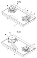
図1は、コンロ本体1の上面に、耐熱性に優れた結晶化ガラスで形成されたガラス天板2を装着したドロップイン式のコンロを示している。ガラス天板2には、左右一対のコンロ開口3a,3bが開設されている。そして、コンロ本体1内に、各コンロ開口3a,3bに臨ませて、左バーナ4a及び右バーナ4b(本発明の加熱手段に相当する)が設けられている。また、コンロ開口3a,3bには、調理容器を載置する五徳5a,5bが配置され、ガラス天板2の上面の手前側に、左バーナ4a及び右バーナ4bの作動を指示するための操作部6が設けられている。
FIG. 1 shows a drop-in type stove in which a glass top plate 2 made of crystallized glass having excellent heat resistance is mounted on the upper surface of a stove body 1. The glass top plate 2 is provided with a pair of left and right stove openings 3a and 3b. The stove body 1 is provided with a left burner 4a and a
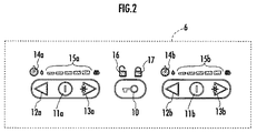
図2を参照して、操作部6には、コンロに電源が投入された状態で、左バーナ4a及び右バーナ4bの作動指示が可能な「運転状態」と該作動指示が不能な「待機状態」とに切り換える運転スイッチ10が備えられている。また、左バーナ4aの作動を指示するために、左バーナ4aを点火準備状態とする点火準備スイッチ11a、左バーナ4aの火力を5段階に切り換える火力DOWNスイッチ12aと火力UPスイッチ13a、左バーナ4aが点火準備状態にあるときと左バーナ4aの作動中に点灯する点火準備表示部14a、及び左バーナ4aの火力設定を表示する火力レベル表示部15aが設けられている。
Referring to FIG. 2, the
なお、左バーナ4aが点火準備状態にあるときに、火力UPスイッチ13aが操作されたときには、左バーナ4aの点火処理が実行される。また、左バーナ4aの燃焼中に点火準備スイッチ11a又は運転スイッチ10が操作されたときは、左バーナ4aの消火処理が実行される。
When the left power burner 4a is operated while the left burner 4a is in the ignition ready state, the left burner 4a is ignited. Further, when the ignition preparation switch 11a or the
同様に、右バーナ4bの作動を指示するために、右バーナ4bを点火準備状態とする点火準備スイッチ11b、右バーナ4bの火力を5段階に切り換える火力DOWNスイッチ12bと火力UPスイッチ13b、右バーナ4bが点火準備状態にあるときと右バーナ4bの作動中に点灯する点火準備表示部14b、及び右バーナ4bの火力設定を表示する火力レベル表示部15bが設けられている。
Similarly, in order to instruct the operation of the
なお、右バーナ4bが点火準備状態にあるときに、火力UPスイッチ13bが操作されたときには、右バーナ4bの点火処理が実行される。また、右バーナ4bの燃焼中に点火準備スイッチ11b又は運転スイッチ10が操作されたときは、右バーナ4bの消火処理が実行される。
Note that when the heating
さらに、操作部6には、「運転状態」にあるときに点灯するアンロック表示部16と、運転スイッチ10が所定時間(例えば4秒)以上連続して操作されて、全てのスイッチの操作が不能ないわゆるチャイルドロック状態となったときに点灯するロック表示部17とが備えられている。
In addition, the
ここで、操作部6の各スイッチは、ガラス天板2の裏面に設けられた静電容量センサと、該静電容量センサと対向したガラス天板2の表面部分にプリントされて各スイッチのタッチポイントを示すプリント部分とにより構成された無接点型のタッチスイッチである。そして、該プリント部分(静電容量センサに対向したガラス天板2の表面部分)に静電体が置かれているときは、静電容量センサにより該静電体が検出されてタッチスイッチはon状態(本発明の検知状態に相当する)となる。一方、該プリント部分に静電体が置かれていないときには、静電容量センサにより該静電体が検出されず、タッチスイッチはoff状態(本発明の非検知状態に相当する)となる。
Here, each switch of the
また、操作部6の各表示部は、ガラス天板2の裏面に設けられたLEDと、該LEDと対向したガラス天板2の表面部分にプリントされたプリント部分とにより構成される。そして、LEDをONしたときに表示部が点灯状態になり、LEDをOFFしたときに表示部は消灯状態となる。
Moreover, each display part of the
また、火力レベル表示部15aは、左バーナ4aの火力レベル(レベル1〜レベル5)を、図示した5個の点灯部分からなるバー表示の左側からの点灯部分の点灯個数で表示する。例えば、左バーナ4aの火力レベルが1であるときはバー表示の左端の点灯部分のみを点灯し、左バーナ4aの火力レベルが5であるときはバー表示の5個の点灯部分が全て点灯する。同様に、火力レベル表示部15bは、右バーナ4bの火力レベル(レベル1〜レベル5)を、図示した5個の点灯部分からなるバー表示の左側からの点灯部分の点灯個数で表示する。
Further, the thermal power
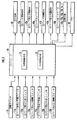
次に、図3を参照して、コンロ本体1内には、コンロの全体的な作動を制御するコントローラ30が備えられ、操作部6の各スイッチ(運転スイッチ10、点火準備スイッチ11a,11b、火力DOWNスイッチ12a,12b、火力UPスイッチ13a,13b)の操作状態(ON/OFF)の検知信号がコントローラ30に入力される。
Next, referring to FIG. 3, the stove body 1 is provided with a
また、コントローラ30から出力される制御信号によって、コンロ本体1への燃料ガスの供給と遮断とを切り換えるガス元弁40、左バーナ4aへの燃料ガスの供給と遮断とを切り換える左バーナ用開閉弁41a、左バーナ4aへの燃料ガスの供給流量を変更する左バーナ用火力調節弁42a、左バーナ4aの点火電極(図示しない)に高電圧を印加して火花放電を生じさせる左バーナ用イグナイタ43a、右バーナ4bへの燃料ガスの供給と遮断とを切り換える右バーナ用開閉弁41b、右バーナ4bへの燃料ガスの供給流量を変更する右バーナ用火力調節弁42b、右バーナ4bの点火電極(図示しない)に高電圧を印加して火花放電を生じさせる右バーナ用イグナイタ43bの作動が制御される。
Further, a
さらに、コントローラ30からの制御信号によって、操作部6に備えられた各表示部(点火準備表示部14a,14b、火力レベル表示部15a,15b、アンロック表示部16、ロック表示部17)の点灯/消灯と、ブザー18のon/offが制御される。
Further, each display unit (ignition
また、コントローラ30には、左バーナ4aと右バーナ4bの作動を制御する加熱制御手段31と、操作部6に備えられた各表示部の点灯/消灯の制御とブザー18による報知を行う点灯制御手段32とが備えられている。
Further, the
ここで、上述したように、操作部6に設けられたタッチスイッチは、ガラス天板2の上面に所在する静電体の有無を検知するものである。そのため、使用者が指でタッチスイッチに触れた場合の他に、図1(b)に示したように、左バーナ4aのみを使用して鍋20内の調理物を加熱していたときに、調理物のふきこぼれ21が生じ、該ふきこぼれ21が操作部6に達して右バーナ4b用のタッチスイッチがon状態となることが生じ得る。或いは、ガラス天板2上の落下物(布巾、食材等)やガラス天板2上に置かれた調理容器により操作部6が覆われてタッチスイッチがon状態となることも生じ得る。
Here, as described above, the touch switch provided in the
そこで、コントローラ30に備えられた加熱制御手段31は、このように、使用者の操作以外の要因でタッチスイッチがoff状態からon状態に切り換わったときに、誤って左バーナ4aや右バーナ4bの点火処理が実行されないようにするための処理を行う。以下、図4〜図9のフローチャートに従って、かかる処理について説明する。なお、図4〜図9のフローチャートは左バーナ4aに対する処理であるが、右バーナ4bに対する処理も同様である。
Therefore, the heating control means 31 provided in the
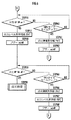
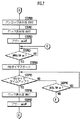
先ず、図4のSTEP1〜STEP6は、運転スイッチ10がoff状態からon状態に切り換わり、さらにoff状態に復帰したことを認識するための処理である。コンロに電源が投入されてコントローラ30が作動を開始すると「待機状態」となり、加熱制御手段31は図4のSTEP1で運転スイッチ10がon状態となるのを待つ。
First, STEP1 to STEP6 in FIG. 4 are processes for recognizing that the
そして、運転スイッチ10がon状態となったときに、STEP2に進んで2秒タイマと4秒タイマをスタートさせ、続くSTEP3とSTEP30からなるループで、STEP30で運転スイッチ10がon状態に維持されていることを確認しながらSTEP3で2秒タイマのタイムアップを待つ。
Then, when the
STEP3で2秒タイマがタイムアップしたとき、すなわち、運転スイッチ10のon状態が2秒以上継続したときはSTEP4に進む。STEP4,STEP5は点灯制御手段32による処理であり、点灯制御手段32はアンロック表示部16を点灯すると共にブザー18を鳴動させ、これにより運転スイッチ10の操作が受け付けられたことを使用者に報知する。
When the 2-second timer expires in STEP 3, that is, when the ON state of the
一方、STEP30で運転スイッチ10がon状態でなくなったときは、ノイズ等により運転スイッチ10が瞬間的にon状態となったと判断できる。そのため、この場合はSTEP1に戻り、加熱制御手段31は、再び運転スイッチ10がoff状態からon状態に切り換わるのを待つ。
On the other hand, when the
加熱制御手段31は、STEP6とSTEP35からなるループで、STEP35で4秒タイマのタイムアップを確認しながらSTEP6で運転スイッチ10がoff状態となるのを待つ。
The heating control means 31 is a loop composed of
STEP6で運転スイッチ10がoff状態となったとき、すなわち、STEP1で運転スイッチ10がon状態となってから4秒が経過する前に運転スイッチ10がoff状態に復帰したときは、STEP7に進んで、加熱制御手段31は15分タイマをスタートさせる。
When the
一方、STEP35で4秒タイマがタイムアップしたとき、すなわち、運転スイッチ10のon状態が4秒以上継続したときは、図7のSTEP80に進む。図7はチャイルドロックの処理であり、点灯制御手段32は、STEP80でアンロック表示部16を消灯し、STEP81でロック表示部17を点灯して、STEP82でブザー18を鳴動させる。
On the other hand, when the 4-second timer expires in STEP 35, that is, when the ON state of the
そして、加熱制御手段31は、次のSTEP83で運転スイッチ10がon状態となるのを待つ。これにより、運転スイッチ10の操作によりチャイルドロック状態が解除されるまで、全てのスイッチに対する操作が不能なチャイルドロック状態となる。チャイルドロック状態で使用者が運転スイッチ10に触れて運転スイッチ10がon状態となると、STEP83からSTEP84に進み、加熱制御手段31は4秒タイマをスタートさせる。
Then, the heating control means 31 waits for the
続いて、加熱制御手段31は、STEP85とSTEP90とからなるループで、STEP90で運転スイッチ10がon状態であるか否かを確認しながらSTEP85で4秒タイマのタイムアップを待つ。STEP85で4秒タイマがタイムアップしたとき、すなわち、チャイルドロック状態で使用者が運転スイッチ10に触れ続けて、運転スイッチ10が4秒以上継続してon状態となったときSTEP86に進む。そして、次のSTEP86で点灯制御手段32がロック表示部17を消灯し、STEP87でブザー18を鳴動させて図4のSTEP1に進む。これによりチャイルドロック状態が解除される。
Subsequently, the heating control means 31 waits for the 4-second timer to expire in STEP 85 while confirming whether or not the
図4のSTEP6で運転スイッチ10がoff状態となったとき、すなわち、STEP1で運転スイッチ10がon状態となってから4秒が経過する前に、運転スイッチ10がoff状態となったときは、STEP7に進み、コントローラ30は15分タイマをスタートさせる。
When the
次に、STEP8〜図5のSTEP14は、点火準備スイッチ11aがoff状態からon状態に切り換わり、さらにoff状態に復帰したことを認識するための処理である。加熱制御手段31は、STEP8とSTEP40からなるループにより、STEP40で15分タイマのタイムアップの有無を確認しながら、STEP8で点火準備スイッチ11aがoff状態からon状態に切り換わるのを待つ。そして、STEP8で点火準備スイッチ11aがon状態となったときに、図5のSTEP9に進む。
Next, STEP 14 to STEP 14 in FIG. 5 are processes for recognizing that the ignition preparation switch 11a has switched from the off state to the on state and has returned to the off state. The heating control means 31 waits for the ignition preparation switch 11a to switch from the off state to the on state in STEP 8 while confirming whether or not the 15-minute timer has expired in
一方、STEP40で15分タイマがタイムアップしたとき、すなわち、STEP6で運転スイッチ10がoff状態になった時から15分が経過するまでに、点火準備スイッチ11aがon状態とならなかったときは、STEP41に進み、コントローラ30はアンロック表示部16を消灯し、STEP42でブザー18を鳴動させてSTEP1に戻り「待機状態」となる。これにより、使用者が運転スイッチ10を操作した後、15分が経過するまでに左バーナ4aの点火操作をしなかったときに、コンロを「待機状態」に復帰させる。
On the other hand, when the 15-minute timer expires in
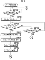
図5のSTEP9で、加熱制御手段31は1秒タイマをスタートさせ、続くSTEP10とSTEP50からなるループにより、STEP50で点火準備スイッチ11aがon状態であるか否かを確認しながらSTEP10で1秒タイマのタイムアップを待つ。そして、STEP10で1秒タイマがタイムアップしたとき、すなわち、点火準備スイッチ11aが1秒以上継続してon状態となったときに、STEP11に進む。
At STEP 9 in FIG. 5, the heating control means 31 starts a one-second timer, and at
一方、STEP50で1秒タイマがタイムアップしたとき、すなわち、点火準備スイッチ11aが1秒未満on状態となったときには、ノイズ等により点火準備スイッチ11aが瞬間的にon状態となったと判断できる。そのため、この場合は図4のSTEP7に戻り、加熱制御手段31は、再び点火準備スイッチ11aがoff状態からon状態に切り換わるのを待つ。
On the other hand, when the 1-second timer expires in STEP 50, that is, when the ignition preparation switch 11a is turned on for less than one second, it can be determined that the ignition preparation switch 11a is instantaneously turned on due to noise or the like. Therefore, in this case, the process returns to STEP 7 in FIG. 4 and the
STEP11〜STEP12は点灯制御手段32による処理であり、点灯制御手段32は、STEP11で点火準備表示部14aを点灯し、STEP12でブザー18を鳴動させる。そして、加熱制御手段31は、STEP13で2秒タイマをスタートさせ、次のSTEP14とSTEP55からなるループにより、STEP55で2秒タイマのタイムアップの有無を確認しながら、STEP14で点火準備スイッチ11aがoff状態となるのを待つ。
STEP11 to STEP12 are processes by the lighting control means 32. The lighting control means 32 lights the ignition preparation display unit 14a in STEP11 and sounds the
STEP14で点火準備スイッチ11aがoff状態となったとき、すなわち、点火準備スイッチ11aが1秒間on状態となった後、2秒以内に点火準備スイッチ11aがon状態からoff状態に復帰したときに、STEP15に進んで、加熱制御手段31は10秒タイマをスタートさせる。 When the ignition preparation switch 11a is turned off in STEP 14, that is, when the ignition preparation switch 11a returns from the on state to the off state within 2 seconds after the ignition preparation switch 11a is turned on for 1 second. Proceeding to STEP 15, the heating control means 31 starts a 10-second timer.
一方、STEP55で2秒タイマがタイムアップしたとき、すなわち、点火準備スイッチ11aが1秒間on状態となった後、さらに2秒間点火準備スイッチ11aが継続してon状態となったときは、STEP56に進む。そして、コントローラ30は、STEP56で点火準備表示部14aを消灯し、STEP57でブザー18を鳴動させて図4のSTEP7に戻る。これにより、煮こぼれ等により点火準備スイッチ11aがon状態に維持される状況となったときには、STEP15以降の処理が禁止され、左バーナ4aの点火処理は実行されない。
On the other hand, when the 2-second timer expires in STEP 55, that is, when the ignition preparation switch 11a is turned on for 1 second after the ignition preparation switch 11a is turned on for 2 seconds, the operation proceeds to STEP 56. move on. Then, the
次に、STEP15〜図6のSTEP19は、火力UPスイッチ13aがoff状態からon状態に切り換わり、さらにoff状態に復帰したことを認識するための処理である。加熱制御手段31は、STEP15で10秒タイマをスタートさせて図6のSTEP16に進み、STEP16とSTEP60からなるループにより、STEP60で10秒タイマのタイムアップの有無を確認しながら、STEP16で火力UPスイッチ13aがoff状態からon状態に切り換わるのを待つ。
Next, STEP 15 to STEP 19 in FIG. 6 are processes for recognizing that the thermal power switch 13a is switched from the off state to the on state and then returned to the off state. The heating control means 31 starts the 10-second timer in STEP 15 and proceeds to STEP 16 in FIG. 6, and confirms whether or not the 10-second timer has timed up in STEP 60 through the loop consisting of
STEP16で火力UPスイッチ13aがon状態となったとき、すなわち、点火準備スイッチ11aがoff状態となってから10秒以内に火力UPスイッチ13aがon状態に切り換わったときは、STEP17に進む。STEP17とSTEP18は点灯制御手段32による処理であり、点灯制御手段32は、STEP17で火力レベル表示部15aをレベル4で点灯し、STEP18でブザー18を鳴動させてSTEP19に進む。
When the heating power UP switch 13a is turned on in
ここで、STEP16で火力UPスイッチ13aがon状態となったときに、後述するSTEP20で実行される左バーナ4aの点火処理に先行して、STEP17で火力レベル表示部15aを点灯させることにより、使用者に点火指示が受け付けられたことを報知している。
Here, when the thermal power UP switch 13a is turned on in
一方、STEP60で10秒タイマがタイムアップしたとき、すなわち、点火準備スイッチ11aがoff状態となってから10秒が経過しても火力UPスイッチ13aがon状態に切り換わらなかったときには、STEP61に進む。STEP61とSTEP62は点灯制御手段32による処理であり、点灯制御手段32は、STEP61で点灯準備表示部14aを消灯し、STEP62でブザー18を鳴動させて図4のSTEP7に戻る。これにより、加熱制御手段31は、再び点火準備スイッチ11aがoff状態からon状態に切り換わるのを待つ。
On the other hand, when the 10-second timer expires at STEP 60, that is, when the thermal power UP switch 13a does not turn on even after 10 seconds have elapsed since the ignition preparation switch 11a is turned off, the routine proceeds to STEP 61. . STEP 61 and STEP 62 are processes by the lighting control means 32. The lighting control means 32 turns off the lighting preparation display section 14a in STEP 61, sounds the
加熱制御手段31は、STEP19とSTEP65からなるループにより、STEP65で10秒タイマのタイムアップの有無を確認しながらSTEP19で火力UPスイッチ13aがoff状態に復帰するのを待つ。そして、STEP19で火力UPスイッチ13aがoff状態に復帰したときにSTEP20に進み、加熱制御手段31は、イグナイタ43aを作動させて点火電極に火花放電を生じさせた状態で、ガス元弁40と左バーナ用開閉弁41aを開弁し、左バーナ用火力調節弁42aを火力レベル4に設定して左バーナ4aの点火処理を実行する。
The heating control means 31 waits for the heating UP switch 13a to return to the OFF state in STEP 19 while confirming whether or not the 10-second timer has expired in STEP 65 by a loop composed of STEP 19 and STEP 65. Then, when the heating power UP switch 13a returns to the OFF state in STEP 19, the process proceeds to STEP 20, and the heating control means 31 operates the igniter 43a to generate a spark discharge in the
一方、STEP65で10秒タイマがタイムアップしたとき、すなわち点火準備スイッチ11aがon状態となってから10秒以内に、火力UPスイッチ13aがoff状態からon状態に切り換わり、さらにoff状態に復帰しなかったときは、STEP66に進む。STEP66からSTEP68は点灯制御手段32による処理であり、点灯制御手段32は、STEP66で点火準備表示部14aを消灯し、STEP67で火力レベル表示部15aを消灯し、STEP68でブザー18を鳴動させて図4のSTEP7に戻る。
On the other hand, when the 10-second timer expires in STEP 65, that is, within 10 seconds after the ignition preparation switch 11a is turned on, the thermal power switch 13a switches from the off state to the on state, and further returns to the off state. If not, go to STEP 66. STEP 66 to STEP 68 are processes by the lighting control means 32. The lighting control means 32 turns off the ignition preparation display section 14a in STEP 66, turns off the thermal power
以上説明したように、加熱制御手段31は、運転スイッチ10がoff状態→on状態→off状態と切り換わった後、点火準備スイッチ11aがoff状態→on状態→off状態と切り換わり、さらに火力UPスイッチ13aがoff状態→on状態→off状態と切り換わったときに、左バーナ4aの点火処理を実行する。
As described above, the heating control means 31 switches the ignition preparation switch 11a from the off state to the on state to the off state after the
そのため、煮こぼれ等により運転スイッチ10、点火準備スイッチ11a、及び火力UPスイッチ13aがoff状態からon状態に切り換わっても左バーナ4aに点火されることはない。また、これらの3個のスイッチが、運転スイッチ10→点火準備スイッチ11a→火力UPスイッチ13aという予め設定された順序で、各スイッチがoff状態→on状態→off状態と切り換わった場合にのみ、左バーナ4aの点火処理が実行される。
Therefore, even if the
そして、煮こぼれ等により、この順序で各スイッチがoff状態→on状態→off状態と切り換わる状況となることは想定し難いため、使用者の操作以外の要因により左バーナ4aの点火処理が実行されることを確実に防止することができる。 Since it is difficult to assume that the switches will be switched from the off state to the on state to the off state in this order due to boiling, etc., the ignition process of the left burner 4a is executed due to factors other than the user's operation. Can be reliably prevented.
次に、図8,図9はバーナの消火操作のフローチャートであり、図8はバーナ燃焼中に運転スイッチ10がon状態となった場合のフローチャートを示し、図9はバーナ燃焼中に点火準備スイッチ11aがon状態となった場合のフローチャートを示している。
Next, FIGS. 8 and 9 are flowcharts of the burner fire extinguishing operation, FIG. 8 shows a flowchart when the
先ず、図8を参照して、左バーナ4aの燃焼中に運転スイッチ10がon状態になったときに、STEP100からSTEP101に進み、コントローラ30は1秒タイマをスタートさせる。そして、STEP102とSTEP110からなるループにより、STEP110で運転スイッチ10がon状態にあるか否かを確認しながらSTEP102で1秒タイマのタイムアップを待つ。
First, referring to FIG. 8, when the
STEP102で1秒タイマがタイムアップしたとき、すなわち、運転スイッチ10が1秒以上継続してon状態となったときはSTEP103に進む。STEP103からSTEP105及びSTEP107は点灯制御手段32による処理であり、点灯制御手段32は、STEP103〜STEP105で点火準備表示部14aと火力レベル表示部15aとアンロック表示部16を消灯する。
When the 1-second timer expires in
そして、次のSTEP106で加熱制御手段31は左バーナ用開閉弁41aとガス元弁40を閉弁して左バーナ4aを消火し、STEP107で点灯制御手段32がブザー18を鳴動させてバーナ4aの消火を報知し、図4のSTEP1に戻る。
Then, in the next STEP 106, the heating control means 31 closes the left burner on-off
次に、図9を参照して、左バーナ4aの燃焼中に点火準備スイッチ11aがon状態になったときに、STEP120からSTEP121に進み、コントローラ30は1秒タイマをスタートさせる。そして、STEP122とSTEP130からなるループにより、STEP130で点火準備スイッチ11aがon状態にあるか否かを確認しながらSTEP122で1秒タイマのタイムアップを待つ。
Next, referring to FIG. 9, when the ignition preparation switch 11 a is turned on during combustion of the left burner 4 a, the process proceeds from
STEP122で1秒タイマがタイムアップしたとき、すなわち、点火準備スイッチ11aが1秒以上継続してon状態となったときはSTEP123に進む。STEP123とSTEP124及びSTEP126は点灯制御手段32による処理であり、点灯制御手段32は、STEP123,STEP124で点火準備表示部14aと火力レベル表示部15aを消灯する。
When the 1-second timer expires in STEP 122, that is, when the ignition preparation switch 11a is continuously turned on for 1 second or more, the process proceeds to STEP 123. STEP123, STEP124, and STEP126 are processes by the lighting control means 32. The lighting control means 32 turns off the ignition preparation display part 14a and the thermal power
そして、次のSTEP125で加熱制御手段31は左バーナ用開閉弁41aを閉弁して左バーナ4aを消火し、STEP126で点灯制御手段32がブザー18を鳴動させてバーナ4aの消火を報知し、図4のSTEP7に戻る。
In the next STEP 125, the heating control means 31 closes the left burner on-off
ここで、上述したように、左バーナ4aの点火処理は、運転スイッチ10と点火準備スイッチ11aと火力UPスイッチ13aが、off状態→on状態→off状態と切り換わったときに実行される。そのため、使用者が左バーナ4aの点火操作をしたときに、運転スイッチ10と点火準備スイッチ11aと火力UPスイッチ13aのいずれもが、OFF故障(スイッチがoff状態からon状態に切り換わらない状態となる故障)状態でなかったことが確認されていたことになる。
Here, as described above, the ignition process of the left burner 4a is executed when the
そこで、図8、図9に示したように、点火操作時にoff故障が生じていなかった運転スイッチ10と点火準備スイッチ11aがoff状態からon状態に切り換わったときに、左バーナ4aの消火処理を実行することで、スイッチのoff故障により左バーナ4aの消火が不能となることを抑制することができる。
Therefore, as shown in FIGS. 8 and 9, when the
なお、本実施の形態では、本発明の加熱手段としてガスバーナ4a,4bを備えたコンロを示したが、電気ヒータ等の他の種類の加熱手段を備えたコンロに対しても本発明の適用が可能である。
In the present embodiment, the stove provided with the
また、本実施の形態では、本発明の天板として耐熱ガラスを用いたガラス天板2を備えたコンロを示したが、ステンレス等の他の素材の天板を備えたコンロに対しても本発明の適用が可能である。 Further, in the present embodiment, the stove provided with the glass top plate 2 using heat-resistant glass as the top plate of the present invention is shown, but the present also applies to the stove provided with a top plate made of other materials such as stainless steel. The invention can be applied.
また、本実施の形態では、本発明のタッチスイッチとして静電容量型のタッチスイッチを採用したコンロを示したが、タッチスイッチの種類はこれに限られず、赤外線の発行部/受光部を備えたフォトスイッチやタクトスイッチ等の機械接点式のタッチスイッチを採用したコンロであっても、本発明の適用が可能である。 In this embodiment, a stove using a capacitive touch switch as the touch switch of the present invention is shown. However, the type of the touch switch is not limited to this, and an infrared emitting / receiving unit is provided. The present invention can be applied even to a stove that employs a mechanical contact type touch switch such as a photo switch or a tact switch.
1…コンロ本体、2…ガラス天板、4a…左バーナ、4b…右バーナ、6…操作部、10…運転スイッチ、11a,11b…点火準備スイッチ、12a,12b…火力DOWNスイッチ、13a,13b…火力UPスイッチ、14a,14b…点火準備表示部、15a,15b…火力レベル表示部、16…アンロック表示部、17…ロック表示部 DESCRIPTION OF SYMBOLS 1 ... Stove body, 2 ... Glass top plate, 4a ... Left burner, 4b ... Right burner, 6 ... Operation part, 10 ... Operation switch, 11a, 11b ... Ignition preparation switch, 12a, 12b ... Thermal power DOWN switch, 13a, 13b ... Thermal power UP switch, 14a, 14b ... Ignition preparation display section, 15a, 15b ... Thermal power level display section, 16 ... Unlock display section, 17 ... Lock display section
Claims (4)
該タッチスイッチが検知状態にあるか非検知状態にあるかを把握し、把握結果に応じて前記加熱手段の作動を制御する加熱制御手段とを備えたコンロにおいて、
前記加熱制御手段は、前記加熱手段が停止状態であって、前記タッチスイッチが非検知状態から検知状態に切り換わった後に非検知状態に復帰したときに、前記加熱手段の作動を開始し、
前記加熱手段が作動状態であって、前記タッチスイッチが非検知状態から検知状態に切り換わったときに、前記加熱手段の作動を停止することを特徴とするコンロ。 Provided on the top plate covering the upper surface of the stove main body that accommodates the heating means, in order to instruct the user to start and stop the operation of the heating means, and detects a contact or approaching object to the upper surface of the top plate A touch switch,
In a stove comprising a heating control means for grasping whether the touch switch is in a detection state or a non-detection state, and controlling the operation of the heating means according to the grasping result,
The heating control means starts the operation of the heating means when the heating means is in a stopped state and the touch switch returns to the non-detection state after switching from the non-detection state to the detection state.
A stove, wherein the heating means is stopped when the heating means is in an operating state and the touch switch is switched from a non-detecting state to a detecting state.
前記加熱制御手段は、前記加熱手段が停止状態であって、複数個のタッチスイッチのうちの予め選択された少なくとも2個のタッチスイッチが、予め設定された順番で、非検知状態から検知状態に切り換わった後に非検知状態に復帰したときに、前記加熱手段の作動を開始することを特徴とする請求項1記載のコンロ。 A plurality of touch switches;
In the heating control unit, the heating unit is in a stopped state, and at least two touch switches selected in advance from a plurality of touch switches are changed from a non-detection state to a detection state in a preset order. The stove according to claim 1, wherein the operation of the heating unit is started when the non-detection state is restored after switching.
前記加熱手段の作動中に前記点灯手段を点灯させると共に、前記加熱手段が停止状態にあるときに、前記タッチスイッチが非検知状態から検知状態に切り換わったときには、前記加熱制御手段による前記加熱手段の作動開始に先行して、前記点灯手段を点灯させる点灯制御手段とを備えたことを特徴とする請求項1から請求項3のうちいずれか1項記載のコンロ。 Lighting means provided on the top plate;
The lighting means is turned on during the operation of the heating means, and the heating means by the heating control means when the touch switch is switched from the non-detection state to the detection state when the heating means is in a stopped state. The stove according to any one of claims 1 to 3, further comprising a lighting control unit that lights the lighting unit prior to the start of the operation.
Priority Applications (6)
| Application Number | Priority Date | Filing Date | Title |
|---|---|---|---|
| JP2004102483A JP2005291512A (en) | 2004-03-31 | 2004-03-31 | Stove |
| TW094106250A TWI275749B (en) | 2004-03-31 | 2005-03-02 | Cookstove |
| US11/091,701 US7422010B2 (en) | 2004-03-31 | 2005-03-29 | Cooking stove |
| EP05006879A EP1582817A1 (en) | 2004-03-31 | 2005-03-30 | Cooking stove |
| KR1020050026882A KR100598547B1 (en) | 2004-03-31 | 2005-03-31 | range |
| CN2005100637701A CN1677000B (en) | 2004-03-31 | 2005-03-31 | Cooking stove |
Applications Claiming Priority (1)
| Application Number | Priority Date | Filing Date | Title |
|---|---|---|---|
| JP2004102483A JP2005291512A (en) | 2004-03-31 | 2004-03-31 | Stove |
Publications (1)
| Publication Number | Publication Date |
|---|---|
| JP2005291512A true JP2005291512A (en) | 2005-10-20 |
Family
ID=35324642
Family Applications (1)
| Application Number | Title | Priority Date | Filing Date |
|---|---|---|---|
| JP2004102483A Pending JP2005291512A (en) | 2004-03-31 | 2004-03-31 | Stove |
Country Status (3)
| Country | Link |
|---|---|
| JP (1) | JP2005291512A (en) |
| KR (1) | KR100598547B1 (en) |
| TW (1) | TWI275749B (en) |
Cited By (3)
| Publication number | Priority date | Publication date | Assignee | Title |
|---|---|---|---|---|
| KR100598547B1 (en) | 2004-03-31 | 2006-07-10 | 린나이코리아 주식회사 | range |
| WO2007058058A1 (en) * | 2005-11-16 | 2007-05-24 | Matsushita Electric Industrial Co., Ltd. | Cooking device |
| JP2013029225A (en) * | 2011-07-27 | 2013-02-07 | Mitsubishi Electric Corp | Heating apparatus and method for determining operation of heating apparatus |
Family Cites Families (6)
| Publication number | Priority date | Publication date | Assignee | Title |
|---|---|---|---|---|
| US5241463A (en) | 1989-06-05 | 1993-08-31 | White Consolidated Industries, Inc. | Control system for gas burners |
| JP2521367B2 (en) | 1990-08-10 | 1996-08-07 | 富士工業株式会社 | Electric cooker switch device |
| US6198080B1 (en) | 1999-08-05 | 2001-03-06 | General Electric Company | Glass touch cooktop dual element and bridge burner control |
| WO2001029483A1 (en) | 1999-10-18 | 2001-04-26 | Pierre Repper | Electronic gas cooktop control with simmer system and method thereof |
| JP2005291512A (en) | 2004-03-31 | 2005-10-20 | Rinnai Corp | Stove |
| US7422010B2 (en) | 2004-03-31 | 2008-09-09 | Rinnai Corporation | Cooking stove |
-
2004
- 2004-03-31 JP JP2004102483A patent/JP2005291512A/en active Pending
-
2005
- 2005-03-02 TW TW094106250A patent/TWI275749B/en not_active IP Right Cessation
- 2005-03-31 KR KR1020050026882A patent/KR100598547B1/en not_active Expired - Fee Related
Cited By (5)
| Publication number | Priority date | Publication date | Assignee | Title |
|---|---|---|---|---|
| KR100598547B1 (en) | 2004-03-31 | 2006-07-10 | 린나이코리아 주식회사 | range |
| WO2007058058A1 (en) * | 2005-11-16 | 2007-05-24 | Matsushita Electric Industrial Co., Ltd. | Cooking device |
| CN100556218C (en) * | 2005-11-16 | 2009-10-28 | 松下电器产业株式会社 | heating cooker |
| US7947924B2 (en) | 2005-11-16 | 2011-05-24 | Panasonic Corporation | Cooking device |
| JP2013029225A (en) * | 2011-07-27 | 2013-02-07 | Mitsubishi Electric Corp | Heating apparatus and method for determining operation of heating apparatus |
Also Published As
| Publication number | Publication date |
|---|---|
| TWI275749B (en) | 2007-03-11 |
| TW200535381A (en) | 2005-11-01 |
| KR20060045154A (en) | 2006-05-16 |
| KR100598547B1 (en) | 2006-07-10 |
Similar Documents
| Publication | Publication Date | Title |
|---|---|---|
| JP2005315438A (en) | Cooking stove | |
| JP6707323B2 (en) | Gas stove | |
| JP2001141244A (en) | Gas heater | |
| JP4115343B2 (en) | Stove | |
| JP2005331116A (en) | Cooking stove | |
| US7335861B2 (en) | Cooking stove | |
| JP2005291509A (en) | Cookstove | |
| JP4064942B2 (en) | Stove | |
| US7422010B2 (en) | Cooking stove | |
| JP2005291512A (en) | Stove | |
| TWI275747B (en) | Cooking stove | |
| JP3544469B2 (en) | Cooking device | |
| JP2005291511A (en) | Cookstove | |
| JP4364680B2 (en) | Gas fired cookware | |
| JP4375795B2 (en) | Stove | |
| JP6998262B2 (en) | Cooking system | |
| JP4617466B2 (en) | Cooker | |
| JPH07167428A (en) | Combustion control device |
Legal Events
| Date | Code | Title | Description |
|---|---|---|---|
| A621 | Written request for application examination |
Free format text: JAPANESE INTERMEDIATE CODE: A621 Effective date: 20051021 |
|
| A977 | Report on retrieval |
Free format text: JAPANESE INTERMEDIATE CODE: A971007 Effective date: 20070521 |
|
| A131 | Notification of reasons for refusal |
Free format text: JAPANESE INTERMEDIATE CODE: A131 Effective date: 20070619 |
|
| A521 | Request for written amendment filed |
Free format text: JAPANESE INTERMEDIATE CODE: A523 Effective date: 20070813 |
|
| A02 | Decision of refusal |
Free format text: JAPANESE INTERMEDIATE CODE: A02 Effective date: 20071127 |