JP4064942B2 - Stove - Google Patents
Stove Download PDFInfo
- Publication number
- JP4064942B2 JP4064942B2 JP2004110388A JP2004110388A JP4064942B2 JP 4064942 B2 JP4064942 B2 JP 4064942B2 JP 2004110388 A JP2004110388 A JP 2004110388A JP 2004110388 A JP2004110388 A JP 2004110388A JP 4064942 B2 JP4064942 B2 JP 4064942B2
- Authority
- JP
- Japan
- Prior art keywords
- switch
- state
- heating
- heating means
- detection state
- Prior art date
- Legal status (The legal status is an assumption and is not a legal conclusion. Google has not performed a legal analysis and makes no representation as to the accuracy of the status listed.)
- Expired - Lifetime
Links
- 238000010438 heat treatment Methods 0.000 claims description 131
- 238000002360 preparation method Methods 0.000 claims description 59
- 238000001514 detection method Methods 0.000 claims description 48
- 238000000034 method Methods 0.000 claims description 42
- 238000010411 cooking Methods 0.000 claims description 10
- 239000011521 glass Substances 0.000 description 25
- 239000007789 gas Substances 0.000 description 6
- 235000013305 food Nutrition 0.000 description 5
- 239000002737 fuel gas Substances 0.000 description 5
- 238000002485 combustion reaction Methods 0.000 description 2
- 238000010586 diagram Methods 0.000 description 2
- 230000000694 effects Effects 0.000 description 2
- 125000002066 L-histidyl group Chemical group [H]N1C([H])=NC(C([H])([H])[C@](C(=O)[*])([H])N([H])[H])=C1[H] 0.000 description 1
- 208000003443 Unconsciousness Diseases 0.000 description 1
- 238000009835 boiling Methods 0.000 description 1
- 239000000463 material Substances 0.000 description 1
- 229910001220 stainless steel Inorganic materials 0.000 description 1
- 239000010935 stainless steel Substances 0.000 description 1
Images


Classifications
-
- A—HUMAN NECESSITIES
- A47—FURNITURE; DOMESTIC ARTICLES OR APPLIANCES; COFFEE MILLS; SPICE MILLS; SUCTION CLEANERS IN GENERAL
- A47K—SANITARY EQUIPMENT NOT OTHERWISE PROVIDED FOR; TOILET ACCESSORIES
- A47K5/00—Holders or dispensers for soap, toothpaste, or the like
- A47K5/06—Dispensers for soap
- A47K5/12—Dispensers for soap for liquid or pasty soap
- A47K5/1211—Dispensers for soap for liquid or pasty soap using pressure on soap, e.g. with piston
-
- B—PERFORMING OPERATIONS; TRANSPORTING
- B05—SPRAYING OR ATOMISING IN GENERAL; APPLYING FLUENT MATERIALS TO SURFACES, IN GENERAL
- B05B—SPRAYING APPARATUS; ATOMISING APPARATUS; NOZZLES
- B05B11/00—Single-unit hand-held apparatus in which flow of contents is produced by the muscular force of the operator at the moment of use
- B05B11/0005—Components or details
- B05B11/0037—Containers
-
- B—PERFORMING OPERATIONS; TRANSPORTING
- B05—SPRAYING OR ATOMISING IN GENERAL; APPLYING FLUENT MATERIALS TO SURFACES, IN GENERAL
- B05B—SPRAYING APPARATUS; ATOMISING APPARATUS; NOZZLES
- B05B11/00—Single-unit hand-held apparatus in which flow of contents is produced by the muscular force of the operator at the moment of use
- B05B11/01—Single-unit hand-held apparatus in which flow of contents is produced by the muscular force of the operator at the moment of use characterised by the means producing the flow
- B05B11/10—Pump arrangements for transferring the contents from the container to a pump chamber by a sucking effect and forcing the contents out through the dispensing nozzle
- B05B11/1001—Piston pumps
Landscapes
- Health & Medical Sciences (AREA)
- Public Health (AREA)
- Electric Stoves And Ranges (AREA)
Description
本発明は、加熱手段を備えたコンロに関し、特に天板の上面に加熱手段の作動を指示するための操作部を備えたコンロに関する。 The present invention relates to a stove provided with heating means, and more particularly to a stove provided with an operation unit for instructing the operation of the heating means on the top surface of the top plate.
従来より、図8に示したように、システムキッチンのカウンタトップに用意された開口にコンロ本体101を埋設するドロップイン式のコンロにおいて、ガスバーナ100a,100bが収容されるコンロ本体101の上面を覆うガラス天板102に、ガスバーナ100a,100bの点火/消火と火力調節を行うための操作つまみ103a,103bを設けたものが知られている(例えば特許文献1参照)。
Conventionally, as shown in FIG. 8, in a drop-in type stove in which a
かかるコンロによれば、前面に操作部を備えたコンロを設置する場合のように、カウンタトップの前面に操作部を臨ませる開口を設ける必要がなく、カウンタトップへのコンロの設置も容易に行うことができる。また、ガスバーナの点火/消火や火力調節を天板102に設けられて視認性が良い操作つまみ103a,103bにより行うことができるため、使用者の操作性が向上する。
図8に示したコンロによれば、操作つまみ103a,103bがガラス天板102の上面に突出して配置されているため、調理を行う際に邪魔になる場合がある。そこで、ガスバーナ100a,100bの操作手段として、例えば、静電容量式のセンサの検出部をガラス天板102の裏面に設けてガラス天板102の表面に操作部を備えたタッチスイッチを構成し、ガラス天板102の上面をフラットにすることが考えられる。
According to the stove shown in FIG. 8, since the
しかし、このようにガラス天板102に表面にタッチスイッチを設けた場合、調理中に使用者が無意識にタッチスイッチに触れてしまうことが生じ得る。また、子供がいたずらをしてタッチスイッチに触れたり、五徳104a,104bに載置したなべ等からの調理物の煮こぼれや、ガラス天板102に置かれた調理容器やガラス天板102への落下物等によりタッチスイッチが覆われることも生じ得る。
However, when the touch switch is provided on the surface of the
そして、これらの要因により、例えば左バーナ100aの点火を指示するためのタッチスイッチがoff状態からon状態に切り換わると、左バーナ100aが点火されてしまうという不都合がある。
Due to these factors, for example, when the touch switch for instructing ignition of the
そこで、本発明はかかる不都合を解消し、使用者の意に反してタッチスイッチが非検知状態から検知状態に切り換わったときに、バーナの点火処理がなされることを防止したコンロを提供することを目的とする。 Accordingly, the present invention provides a stove that eliminates such inconvenience and prevents the burner from being ignited when the touch switch switches from the non-detection state to the detection state against the will of the user. With the goal.
本発明は上記目的を達成するためになされたものであり、2個以上の加熱手段と、該加熱手段を収容するコンロ本体の上面を覆う天板に、使用者が該加熱手段の作動を指示するために設けられて、該天板の上面への接触物又は接近物を検知する複数個のタッチスイッチと、該タッチスイッチが検知状態にあるか非検知状態にあるかを把握し、把握結果に応じて、少なくとも前記加熱手段の作動開始の処理を実行する加熱制御手段とを備えたコンロの改良に関する。 The present invention has been made in order to achieve the above object, an instruction and two or more heating means, the top plate covering the upper surface of the cooking stove main body accommodating the heating means, the user actuation of the heating means A plurality of touch switches provided to detect a contact object or approaching object to the top surface of the top plate, and whether the touch switch is in a detection state or a non-detection state; Accordingly, the present invention relates to an improvement of a stove provided with at least a heating control means for executing an operation start process of the heating means.
そして、前記2個以上の加熱手段に対して個別に設けられて、対応する加熱手段の加熱量を変更する加熱量変更手段とを備え、前記複数個のタッチスイッチのうちの1個は、使用者による他のタッチスイッチの操作が可能な運転状態と、使用者による他のタッチスイッチの操作が不能な待機状態とを切換える運転スイッチであり、前記複数個のタッチスイッチには、前記2個以上の加熱手段に対して個別に設けられた、各加熱手段の作動を許可するための作動準備スイッチと、前記加熱量変更手段による各加熱手段の加熱量の増加を指示するための加熱量UPスイッチとが含まれ、前記加熱制御手段は、前記運転スイッチが非検知状態から検知状態に切り換わったときに、前記待機状態から前記運転状態に移行し、その後前記運転スイッチが検知状態から非検知状態に復帰した時から第1の所定時間が経過するまでの間に、前記作動準備スイッチのいずれも操作されなかったときは前記待機状態に移行し、該復帰した時から該第1の所定時間が経過するまでの間に、いずれかの加熱手段に対して設けられた前記作動準備スイッチが非検知状態から検知状態に切り換わったときには、その後、該作動準備スイッチが、該第1の所定時間よりも短い第2の所定時間が経過するまでの間に検知状態から非検知状態に切り換わるか否かを判断して、該作動準備スイッチが該第2の所定時間が経過するまでの間に検知状態から非検知状態に切り換わったときは、その後に前記加熱量UPが非検知状態か検知状態に切り換わってから非検知状態に復帰したときに、前記加熱手段の作動開始の処理を実行し、該作動準備スイッチが該第2の所定時間が経過するまでの間に非検知状態に切り換わらなかったときには、前記加熱手段の作動開始の処理を実行しないことを特徴とする。 And a heating amount changing means provided separately for the two or more heating means and changing the heating amount of the corresponding heating means, wherein one of the plurality of touch switches is used An operation switch that switches between an operation state in which another touch switch can be operated by a user and a standby state in which another user cannot operate the other touch switch. An operation preparation switch for allowing the operation of each heating means, and a heating amount UP switch for instructing an increase in the heating amount of each heating means by the heating amount changing means. Doo is included, the heating control means, when the operation switch is switched to the detection state from the non-sensing state, and proceeds from the standby state to the operating state, after which the operation switch When none of the operation preparation switches is operated during the period from the return from the knowledge state to the non-detection state until the first predetermined time elapses, the state shifts to the standby state. When the operation preparation switch provided for any one of the heating means switches from the non-detection state to the detection state until the first predetermined time elapses, the operation preparation switch is It is determined whether or not the detection state is switched to the non-detection state until the second predetermined time shorter than the first predetermined time elapses, and the operation preparation switch has passed the second predetermined time. When the detection state is switched from the detection state to the non-detection state until the heating is performed, the heating means is activated when the heating amount UP is switched from the detection state to the detection state and then returned to the non-detection state. Start processing Run, the acting dynamic ready switch when not switch to a non-detection state until the elapse of the predetermined time of the second is characterized in that it does not perform the operation start of the process of the heating means.
かかる本発明によれば、前記加熱制御手段は、予め選択された少なくとも2個のタッチスイッチが、非検知状態から検知状態に切り換わったときに、前記加熱手段の作動開始の処理を行う。そのため、使用者が無意識に1個のタッチスイッチに触れたときや、子供のいたずらや調理物の煮こぼれによって1個のタッチスイッチのみが非検知状態から検知状態に切り換わったときには、前記加熱手段は作動しない。そして、これにより、使用者の意に反して前記加熱手段の作動が開始されることを防止することができる。 According to the present invention, the heating control means performs an operation start process of the heating means when at least two touch switches selected in advance are switched from the non-detection state to the detection state. Therefore, when the user unintentionally touches one touch switch, or when only one touch switch is switched from the non-detection state to the detection state due to mischief of the child or spilled food, the heating means Does not work. And thereby, it can prevent starting the action | operation of the said heating means contrary to a user's will.
また、本発明によれば、前記加熱量UPスイッチを前記加熱手段の作動開始を指示するためのスイッチとして転用することで、用意する必要があるタッチスイッチの個数を減らすことができる。また、前記加熱手段の作動開始の処理は、概念的には「加熱量の増加の指示」に含まれるため、前記加熱手段の作動開始の指示を前記加熱量UPスイッチの操作によって行うことに対する使用者の違和感は少なく、使用者の使い勝手は良いと考えられる。 In addition, according to the present invention, the number of touch switches that need to be prepared can be reduced by diverting the heating amount UP switch as a switch for instructing the start of the operation of the heating means. Further, since the processing for starting the operation of the heating means is conceptually included in the “instruction to increase the heating amount”, the use for performing the instruction to start the operation of the heating means by operating the heating amount UP switch. The user feels uncomfortable and the user-friendliness is considered good.
また、本発明によれば、前記待機状態からいずれかの加熱手段の作動開始の指示を行う場合、使用者は先ず前記運転スイッチを操作して前記待機状態から前記運転状態に切り換える必要がある。そのため、他のいずれか1個のタッチスイッチが非検知状態から検知状態に切り換わったときに、前記加熱手段の作動開始の処理を実行するようにしても、前記加熱手段の作動開始を指示するためには、2個のタッチスイッチの操作が必要となる。 Further , according to the present invention, when an instruction to start the operation of any of the heating means is given from the standby state, the user must first operate the operation switch to switch from the standby state to the operation state. For this reason, when any one of the touch switches is switched from the non-detection state to the detection state, the operation start of the heating unit is instructed even if the process of starting the operation of the heating unit is executed. For this purpose, two touch switches need to be operated.
しかし、既に前記運転状態とされて、前記2個以上の加熱手段のうちのいずれかが作動中であるときに、他の加熱手段の加熱開始指示を行うときには、前記運転スイッチ以外の他のタッチスイッチが非検知状態から検知状態に切り換わったときに、該他の加熱手段の加熱開始の処理を実行してしまうと、1個のタッチスイッチの操作で該他の加熱手段の加熱が開始される。そして、この場合には、使用者の無意識な操作や、こどものいたずら等により1個のタッチスイッチが非検知状態から検知状態に切り換わったときに、該他の加熱手段の作動が開始されてしまう。 However, when the heating state is already given and one of the two or more heating means is in operation, and other heating means are instructed to start heating, other touches other than the operation switch are used. If the heating start processing of the other heating means is executed when the switch is switched from the non-detection state to the detection state, heating of the other heating means is started by operating one touch switch. The In this case, the operation of the other heating means is started when one touch switch is switched from the non-detection state to the detection state due to the user's unconscious operation or mischief of children. End up.
そこで、本発明により、前記運転スイッチ以外の少なくとも2個のタッチスイッチが非検知状態から検知状態に切り換わったときに、前記加熱手段の作動開始の処理を実行するようにすることによって、前記運転状態であるときに、使用者の意に反して2個以上の前記加熱手段のうちのいずれかの作動開始の処理が実行されることを防止することができる。 Therefore, according to the present invention, when at least two touch switches other than the operation switch are switched from the non-detection state to the detection state, the operation start processing of the heating unit is performed, thereby the operation is performed. When it is in the state, it is possible to prevent the operation start process of any one of the two or more heating means from being executed against the user's will.
また、本発明によれば、前記加熱手段を2個以上備えて、前記作動準備スイッチと前記加熱量UPスイッチとを各加熱手段に対して個別に設ける場合に、前記加熱量UPスイッチを前記加熱手段の作動開始を指示するためのスイッチとして転用することで、各加熱手段に対して作動開始を指示するためのスイッチを専用に設けることが不要となる。そのため、用意する必要があるタッチスイッチの個数を減らすことができる。
さらに、本発明において、前記各加熱手段に対して、各加熱手段に対応した前記作動準備スイッチ及び前記加熱量UPスイッチと、前記運転スイッチとが、前記加熱手段と前記作動準備スイッチ間の距離及び前記加熱手段と前記加熱量UPスイッチ間の距離を、前記加熱手段と前記運転スイッチ間の距離よりも短くして設けられていることが好ましい。 Further , according to the present invention, when two or more heating means are provided and the operation preparation switch and the heating amount UP switch are individually provided for each heating means, the heating amount UP switch is heated. By diverting as a switch for instructing the start of operation of the means, it becomes unnecessary to provide a dedicated switch for instructing the start of operation for each heating means. Therefore, the number of touch switches that need to be prepared can be reduced.
Further, in the present invention, for each of the heating means, the operation preparation switch corresponding to each heating means, the heating amount UP switch, and the operation switch are provided with a distance between the heating means and the operation preparation switch, and It is preferable that the distance between the heating means and the heating amount UP switch is shorter than the distance between the heating means and the operation switch.
本発明の実施の形態について、図1〜図7を参照して説明する。図1は本発明のコンロの外観図、図2は図1に示した操作部の詳細図、図3はコンロの制御ブロック図、図4〜図6はバーナの点火処理のフローチャート、図7はチャイルドロック及びチャイルドロック解除のフローチャートである。 Embodiments of the present invention will be described with reference to FIGS. 1 is an external view of a stove according to the present invention, FIG. 2 is a detailed view of the operation unit shown in FIG. 1, FIG. 3 is a control block diagram of the stove, FIGS. 4 to 6 are flowcharts of burner ignition processing, and FIG. It is a flowchart of child lock and child lock release.
図1は、コンロ本体1の上面に、耐熱性に優れた結晶化ガラスで形成されたガラス天板2を装着したドロップイン式のコンロを示している。ガラス天板2には、左右一対のコンロ開口3a,3bが開設されている。そして、コンロ本体1内に、各コンロ開口3a,3bに臨ませて、左バーナ4a及び右バーナ4b(本発明の加熱手段に相当する)が設けられている。また、コンロ開口3a,3bには、調理容器を載置する五徳5a,5bが配置され、ガラス天板2の上面の手前側に、左バーナ4a及び右バーナ4bの作動を指示するための操作部6が設けられている。
FIG. 1 shows a drop-in type stove in which a
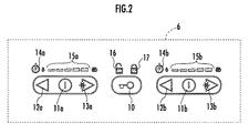
図2を参照して、操作部6に備えられた運転スイッチ10は、コンロに電源が投入された状態で、運転スイッチ10以外の他のスイッチの操作が可能な「運転状態」と、運転スイッチ10以外の他のスイッチの操作が不能な「待機状態」とを切り換えるためのものである。「運転状態」においては、左バーナ4a及び右バーナ4bの作動指示が可能である。
Referring to FIG. 2, the
また、操作部6には、左バーナ4aの作動を指示するために、左バーナ4aの点火を許可する点火準備状態とする点火準備スイッチ11a(本発明の作動準備スイッチに相当する)、左バーナ4aの火力を5段階(レベル1〜レベル5)に切り換える火力DOWNスイッチ12aと火力UPスイッチ13a(本発明の加熱量UPスイッチに相当する)、左バーナ4aが点火準備状態にあるときと左バーナ4aの作動中に点灯する点火準備表示部14a、及び左バーナ4aの火力設定を表示する火力レベル表示部15aが設けられている。
In addition, in order to instruct the operation of the left burner 4a to the operation unit 6, an
なお、左バーナ4aが点火準備状態にあるときに、火力UPスイッチ13aが操作されたときには、左バーナ4aの点火処理が実行される。また、左バーナ4aの燃焼中に点火準備スイッチ11a又は運転スイッチ10が操作されたときは、左バーナ4aの消火処理が実行される。
When the left power burner 4a is operated while the left burner 4a is in the ignition ready state, the left burner 4a is ignited. Further, when the
同様に、右バーナ4bの作動を指示するために、右バーナ4bの点火を許可する点火準備状態とする点火準備スイッチ11b(本発明の作動準備スイッチに相当する)、右バーナ4bの火力を5段階(レベル1〜レベル5)に切り換える火力DOWNスイッチ12bと火力UPスイッチ13b(本発明の加熱量UPスイッチに相当する)、右バーナ4bが点火準備状態にあるときと右バーナ4bの作動中に点灯する点火準備表示部14b、及び右バーナ4bの火力設定を表示する火力レベル表示部15bが設けられている。
Similarly, in order to instruct the operation of the
なお、右バーナ4bが点火準備状態にあるときに、火力UPスイッチ13bが操作されたときには、右バーナ4bの点火処理が実行される。また、右バーナ4bの燃焼中に点火準備スイッチ11b又は運転スイッチ10が操作されたときは、右バーナ4bの消火処理が実行される。
Note that when the heating burner UP switch 13b is operated while the
さらに、操作部6には、「運転状態」にあるときに点灯するアンロック表示部16と、運転スイッチ10が所定時間(例えば4秒)以上連続して操作されて、全てのスイッチの操作が不能ないわゆるチャイルドロック状態となったときに点灯するロック表示部17とが備えられている。
In addition, the operation unit 6 is operated in such a manner that the
ここで、操作部6の各スイッチは、ガラス天板2の裏面に設けられた静電容量センサと、該静電容量センサと対向したガラス天板2の表面部分にプリントされて各スイッチのタッチポイントを示すプリント部分とにより構成された無接点型のタッチスイッチである。そして、該プリント部分(静電容量センサに対向したガラス天板2の表面部分)に静電体が置かれているときは、静電容量センサにより該静電体が検出されてタッチスイッチはon状態(本発明の検知状態に相当する)となる。一方、該プリント部分に静電体が置かれていないときには、静電容量センサにより該静電体が検出されず、タッチスイッチはoff状態(本発明の非検知状態に相当する)となる。
Here, each switch of the operation unit 6 is printed on the capacitance sensor provided on the back surface of the
また、操作部6の各表示部は、ガラス天板2の裏面に設けられたLEDと、該LEDと対向したガラス天板2の表面部分にプリントされたプリント部分とにより構成される。そして、LEDをONしたときに表示部が点灯状態になり、LEDをOFFしたときに表示部は消灯状態となる。なお、ガラス天板2の表面部分に前記プリント部分を設けずに、ガラス天板2の裏面に設けられたLED等の点灯手段のみによって、表示部を構成してもよい。
Moreover, each display part of the operation part 6 is comprised by LED provided in the back surface of the
また、火力レベル表示部15aは、左バーナ4aの火力レベル(レベル1〜レベル5)を、図示した5個の点灯部分からなるバー表示の左側からの点灯部分の点灯個数で表示する。例えば、左バーナ4aの火力レベルが1であるときはバー表示の左端の点灯部分のみを点灯し、左バーナ4aの火力レベルが5であるときはバー表示の5個の点灯部分が全て点灯する。同様に、火力レベル表示部15bは、右バーナ4bの火力レベル(レベル1〜レベル5)を、図示した5個の点灯部分からなるバー表示の左側からの点灯部分の点灯個数で表示する。
Further, the thermal power level display unit 15a displays the thermal power level (level 1 to level 5) of the left burner 4a by the number of lighting portions from the left side of the bar display including the five lighting portions illustrated. For example, when the thermal power level of the left burner 4a is 1, only the lighting portion at the left end of the bar display is lit, and when the thermal power level of the left burner 4a is 5, all five lighting portions of the bar display are lit. . Similarly, the thermal power
次に、図3を参照して、コンロ本体1内には、コンロの全体的な作動を制御するコントローラ30が備えられ、操作部6の各スイッチ(運転スイッチ10、点火準備スイッチ11a,11b、火力DOWNスイッチ12a,12b、火力UPスイッチ13a,13b)の操作状態(on/off)の検知信号がコントローラ30に入力される。
Next, referring to FIG. 3, the stove body 1 is provided with a
また、コントローラ30から出力される制御信号によって、コンロ本体1への燃料ガスの供給と遮断とを切り換えるガス元弁40、左バーナ4aへの燃料ガスの供給と遮断とを切り換える左バーナ用開閉弁41a、左バーナ4aへの燃料ガスの供給流量を変更する左バーナ用火力調節弁42a(本発明の加熱量変更手段に相当する)、左バーナ4aの点火電極(図示しない)に高電圧を印加して火花放電を生じさせる左バーナ用イグナイタ43a、右バーナ4bへの燃料ガスの供給と遮断とを切り換える右バーナ用開閉弁41b、右バーナ4bへの燃料ガスの供給流量を変更する右バーナ用火力調節弁42b(本発明の加熱量変更手段に相当する)、右バーナ4bの点火電極(図示しない)に高電圧を印加して火花放電を生じさせる右バーナ用イグナイタ43bの作動が制御される。
Further, a
さらに、コントローラ30から出力される制御信号によって、操作部6に備えられた各表示部(点火準備表示部14a,14b、火力レベル表示部15a,15b、アンロック表示部16、ロック表示部17)の点灯/消灯と、ブザー18のon/offが制御される。
Further, each display unit (ignition
また、コントローラ30には、左バーナ4aと右バーナ4bの作動を制御する加熱制御手段31と、操作部6に備えられた各表示部の点灯/消灯の制御とブザー18による報知を行う点灯制御手段32とが備えられている。
Further, the
ここで、上述したように、操作部6に設けられたタッチスイッチは、ガラス天板2の上面に所在する静電体の有無を検知するものである。そのため、使用者が指でタッチスイッチに触れた場合の他に、図1(b)に示したように、左バーナ4aのみを使用して鍋20内の調理物を加熱していたときに、調理物のふきこぼれ21が生じ、該ふきこぼれ21が操作部6に達して右バーナ4b用のタッチスイッチがoff状態からon状態に切り換わることが生じ得る。
Here, as described above, the touch switch provided in the operation unit 6 detects the presence or absence of an electrostatic body located on the upper surface of the glass
或いは、調理中に使用者が無意識にタッチスイッチに触れた場合や、子供のいたずら、ガラス天板2上の落下物(布巾、食材等)、ガラス天板2上に置かれた調理容器等によりタッチスイッチがoff状態からon状態に切り換わることも生じ得る。
Or, when the user unintentionally touches the touch switch during cooking, a child's mischief, falling objects (clothes, foods, etc.) on the
そこで、コントローラ30に備えられた加熱制御手段31は、このように、使用者の意に反してタッチスイッチがoff状態からon状態に切り変わったときに、誤って左バーナ4aや右バーナbに対する点火操作の指示が受け付けられないようにするための処理を行う。以下、図4〜図7のフローチャートに従って、かかるこれらの処理について説明する。なお、図4〜図7のフローチャートは主として左バーナ4aに対する処理であるが、右バーナ4bに対する処理も同様である。
Thus, the heating control means 31 provided in the
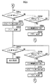
先ず、図4のSTEP1〜STEP6は、運転スイッチ10がOFF状態からON状態に切り換わり、さらにOFF状態に復帰したことを認識するための処理である。コンロに電源が投入されてコントローラ30が作動を開始すると「待機状態」となり、加熱制御手段31は図4のSTEP1で運転スイッチ10がon状態となるのを待つ。
First, STEP 1 to STEP 6 in FIG. 4 are processes for recognizing that the
そして、運転スイッチ10がon状態となったときに、STEP2に進んで2秒タイマと4秒タイマをスタートさせ、続くSTEP3とSTEP30からなるループで、STEP30で運転スイッチ10がon状態に維持されていることを確認しながらSTEP3で2秒タイマのタイムアップを待つ。
Then, when the
STEP3で2秒タイマがタイムアップしたとき、すなわち、運転スイッチ10のon状態が2秒以上継続したときはSTEP4に進む。STEP4,STEP5は点灯制御手段32による処理であり、点灯制御手段32はアンロック表示部16を点灯すると共にブザー18を鳴動させ、これにより運転スイッチ10の操作が受け付けられたことを使用者に報知する。
When the 2-second timer expires in
一方、STEP30で運転スイッチ10がon状態でなくなったときは、ノイズ等により運転スイッチ10が瞬間的にon状態となったと判断できる。そのため、この場合はSTEP1に戻り、加熱制御手段31は、再び運転スイッチ10がoffF状態からon状態に切り換わるのを待つ。
On the other hand, when the
加熱制御手段31は、STEP6とSTEP35からなるループで、STEP35で4秒タイマのタイムアップを確認しながらSTEP6で運転スイッチ10がoff状態となるのを待つ。
The heating control means 31 is a loop composed of STEP 6 and STEP 35 and waits for the
STEP6で運転スイッチ10がoff状態となったとき、すなわち、STEP1で運転スイッチ10がon状態となってから4秒が経過する前に運転スイッチ10がoff状態に復帰したときは、STEP7に進んで、加熱制御手段31は15分タイマをスタートさせる。
When the
一方、STEP35で4秒タイマがタイムアップしたとき、すなわち、運転スイッチ10のon状態が4秒以上継続したときは、図7のSTEP80に進む。図7はチャイルドロックの処理であり、点灯制御手段32は、STEP80でアンロック表示部16を消灯し、STEP81でロック表示部17を点灯して、STEP82でブザー18を鳴動させる。
On the other hand, when the 4-second timer expires in STEP 35, that is, when the ON state of the
そして、加熱制御手段31は、次のSTEP83で運転スイッチ10がon状態となるのを待つ。これにより、運転スイッチ10の操作によりチャイルドロック状態が解除されるまで、全てのスイッチに対する操作が不能なチャイルドロック状態となる。チャイルドロック状態で使用者が運転スイッチ10に触れて運転スイッチ10がon状態となると、STEP83からSTEP84に進み、加熱制御手段31は4秒タイマをスタートさせる。
Then, the heating control means 31 waits for the
続いて、加熱制御手段31は、STEP85とSTEP90とからなるループで、STEP90で運転スイッチ10がON状態であるか否かを確認しながらSTEP85で4秒タイマのタイムアップを待つ。STEP85で4秒タイマがタイムアップしたとき、すなわち、チャイルドロック状態で使用者が運転スイッチ10に触れ続けて、運転スイッチ10が4秒以上継続してon状態となったときSTEP86に進む。そして、次のSTEP86で点灯制御手段32がロック表示部17を消灯し、STEP87でブザー18を鳴動させて図4のSTEP1に進む。これによりチャイルドロック状態が解除される。
Subsequently, the heating control means 31 waits for the 4-second timer to expire in STEP 85 while confirming whether or not the
図4のSTEP6で運転スイッチ10がoff状態となったとき、すなわち、STEP1で運転スイッチ10がon状態となってから4秒が経過する前に、運転スイッチ10がoff状態となったときは、STEP7に進み、コントローラ30は15分タイマをスタートさせる。
When the
次に、STEP8〜図5のSTEP14は、点火準備スイッチ11aがoff状態からon状態に切り換わり、さらにoff状態に復帰したことを認識するための処理である。加熱制御手段31は、STEP8とSTEP40からなるループにより、STEP40で15分タイマのタイムアップの有無を確認しながら、STEP8で点火準備スイッチ11aがoff状態からon状態に切り換わるのを待つ。そして、STEP8で点火準備スイッチ11aがon状態となったときに、図5のSTEP9に進む。
Next, STEP 14 to STEP 14 in FIG. 5 are processes for recognizing that the
一方、STEP40で15分タイマがタイムアップしたとき、すなわち、STEP6で運転スイッチ10がOFF状態になった時から15分が経過するまでに、点火準備スイッチ11aがon状態とならなかったときは、STEP41に進み、コントローラ30はアンロック表示部16を消灯し、STEP42でブザー18を鳴動させてSTEP1に戻り「待機状態」となる。これにより、使用者が運転スイッチ10を操作した後、15分が経過するまでに左バーナ4aの点火操作をしなかったときに、コンロを「待機状態」に復帰させる。
On the other hand, when the 15-minute timer has expired in
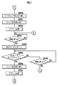
図5のSTEP9で、加熱制御手段31は1秒タイマをスタートさせ、続くSTEP10とSTEP50からなるループにより、STEP50で点火準備スイッチ11aがon状態であるか否かを確認しながらSTEP10で1秒タイマのタイムアップを待つ。そして、STEP10で1秒タイマがタイムアップしたとき、すなわち、点火準備スイッチ11aが1秒以上継続してon状態となったときに、STEP11に進む。
At
一方、STEP50で1秒タイマがタイムアップしたとき、すなわち、点火準備スイッチ11aが1秒未満on状態となったときには、ノイズ等により点火準備スイッチ11aが瞬間的にon状態となったと判断できる。そのため、この場合は図4のSTEP7に戻り、加熱制御手段31は、再び点火準備スイッチ11aがoff状態からon状態に切り換わるのを待つ。
On the other hand, when the 1-second timer expires in STEP 50, that is, when the
STEP11〜STEP12は点灯制御手段32による処理であり、点灯制御手段32は、STEP11で点火準備表示部14aを点灯し、STEP12でブザー18を鳴動させる。そして、加熱制御手段31は、STEP13で2秒タイマをスタートさせ、次のSTEP14とSTEP55からなるループにより、STEP55で2秒タイマのタイムアップの有無を確認しながら、STEP14で点火準備スイッチ11aがoff状態となるのを待つ。
STEP11 to STEP12 are processes by the lighting control means 32. The lighting control means 32 lights the ignition
STEP14で点火準備スイッチ11aがoff状態となったとき、すなわち、点火準備スイッチ11aが1秒間on状態となった後、2秒以内に点火準備スイッチ11aがon状態からoff状態に復帰したときに、STEP15に進んで、加熱制御手段31は10秒タイマをスタートさせる。
When the
一方、STEP55で2秒タイマがタイムアップしたとき、すなわち、点火準備スイッチ11aが1秒間on状態となった後、さらに2秒間点火準備スイッチ11aが継続してon状態となったときは、STEP56に進む。そして、コントローラ30は、STEP56で点火準備表示部14aを消灯し、STEP57でブザー18を鳴動させて図4のSTEP7に戻る。これにより、煮こぼれ等により点火準備スイッチ11aがon状態に維持される状況となったときには、STEP15以降の処理が禁止され、左バーナ4aの点火処理は実行されない。
On the other hand, when the 2-second timer expires in STEP 55, that is, when the
次に、STEP15〜図6のSTEP19は、火力UPスイッチ13aがoff状態からon状態に切り換わり、さらにoff状態に復帰したことを認識するための処理である。加熱制御手段31は、STEP15で10秒タイマをスタートさせて図6のSTEP16に進み、STEP16とSTEP60からなるループにより、STEP60で10秒タイマのタイムアップの有無を確認しながら、STEP16で火力UPスイッチ13aがOFF状態からON状態に切り換わるのを待つ。
Next, STEP 15 to STEP 19 in FIG. 6 are processes for recognizing that the thermal power switch 13a is switched from the off state to the on state and then returned to the off state. The heating control means 31 starts the 10-second timer in STEP 15 and proceeds to STEP 16 in FIG. 6, and confirms whether or not the 10-second timer has timed up in STEP 60 through the loop consisting of
STEP16で火力UPスイッチ13aがon状態となったとき、すなわち、点火準備スイッチ11aがoff状態となってから10秒以内に火力UPスイッチ13aがon状態に切り換わったときは、STEP17に進む。STEP17とSTEP18は点灯制御手段32による処理であり、点灯制御手段32は、STEP17で火力レベル表示部15aをレベル4で点灯し、STEP18でブザー18を鳴動させてSTEP19に進む。
When the heating power UP switch 13a is turned on in
ここで、STEP16で火力UPスイッチ13aがon状態となったときに、後述するSTEP20で実行される左バーナ4aの点火処理に先行して、STEP17で火力レベル表示部15aを点灯させることにより、使用者に点火指示が受け付けられたことを報知している。
Here, when the thermal power UP switch 13a is turned on in
一方、STEP60で10秒タイマがタイムアップしたとき、すなわち、点火準備スイッチ11aがoff状態となってから10秒が経過しても火力UPスイッチ13aがon状態に切り換わらなかったときには、STEP61に進む。STEP61とSTEP62は点灯制御手段32による処理であり、点灯制御手段32は、STEP61で点灯準備表示部14aを消灯し、STEP62でブザー18を鳴動させて図4のSTEP7に戻る。これにより、加熱制御手段31は、再び点火準備スイッチ11aがoff状態からon状態に切り換わるのを待つ。
On the other hand, when the 10-second timer expires at STEP 60, that is, when the thermal power UP switch 13a does not turn on even after 10 seconds have elapsed since the
加熱制御手段31は、STEP19とSTEP65からなるループにより、STEP65で10秒タイマのタイムアップの有無を確認しながらSTEP19で火力UPスイッチ13aがoff状態に復帰するのを待つ。そして、STEP19で火力UPスイッチ13aがoff状態に復帰したときにSTEP20に進み、加熱制御手段31は、イグナイタ43aを作動させて点火電極に火花放電を生じさせた状態で、ガス元弁40と左バーナ用開閉弁41aを開弁し、左バーナ用火力調節弁42aを火力レベル4に設定して左バーナ4aの点火処理(本発明の加熱手段の作動開始の処理に相当する)を実行する。
The heating control means 31 waits for the heating UP switch 13a to return to the OFF state in STEP 19 while confirming whether or not the 10-second timer has expired in STEP 65 by a loop composed of STEP 19 and STEP 65. Then, when the heating power UP switch 13a returns to the OFF state in STEP 19, the process proceeds to STEP 20, and the heating control means 31 operates the igniter 43a to generate a spark discharge in the
一方、STEP65で10秒タイマがタイムアップしたとき、すなわち点火準備スイッチ11aがon状態となってから10秒以内に、火力UPスイッチ13aがoff状態からon状態に切り換わり、さらにoff状態に復帰しなかったときは、STEP66に進む。STEP66からSTEP68は点灯制御手段32による処理であり、点灯制御手段32は、STEP66で点火準備表示部14aを消灯し、STEP67で火力レベル表示部15aを消灯し、STEP68でブザー18を鳴動させて図4のSTEP7に戻る。
On the other hand, when the 10-second timer expires in STEP 65, that is, within 10 seconds after the
以上説明したように、加熱制御手段31は、運転スイッチ10がoff状態→on状態→off状態と切り換わった後、点火準備スイッチ11aがoff状態→on状態→off状態と切り換わり、さらに火力UPスイッチ13aがoff状態→on状態→off状態と切り換わったときに、左バーナ4aの点火処理を実行する。
As described above, the heating control means 31 switches the
そのため、使用者が無意識に操作部6に触れた場合や、子供のいたずら、調理物の煮こぼれ等によって、運転スイッチ10、点火準備スイッチ11a、及び火力UPスイッチ13aのうちのいずれか1個のみがoff状態からon状態に切り換わったとき、或いはさらにon状態からoff状態に復帰したときに、左バーナ4aの点火処理が実行されることがない。
Therefore, only one of the
また、「運転状態」となった後においても、点火準備スイッチ11aと火力UPスイッチ13aのうちのいずれか一方のみがoff状態からon状態に切り換わったとき、或いはさらにon状態からoff状態に復帰したときに、左バーナ4aの点火処理が実行されることがない。
Even after the “running state” is entered, when only one of the
なお、本実施の形態では、本発明の加熱手段としてガスバーナ4a,4bを備えたコンロを示したが、電気ヒータ等の他の種類の加熱手段を備えたコンロに対しても本発明の適用が可能である。
In the present embodiment, the stove provided with the
また、本実施の形態では、本発明のタッチスイッチとして静電容量型のタッチスイッチを採用したコンロを示したが、タッチスイッチの種類はこれに限られず、赤外線の発行部/受光部を備えたフォトスイッチやタクトスイッチ等の機械接点式のタッチスイッチを採用したコンロであっても、本発明の適用が可能である。 In this embodiment, a stove using a capacitive touch switch as the touch switch of the present invention is shown. However, the type of the touch switch is not limited to this, and an infrared emitting / receiving unit is provided. The present invention can be applied even to a stove that employs a mechanical contact type touch switch such as a photo switch or a tact switch.
また、本実施の形態では、本発明の天板として耐熱ガラスを用いたガラス天板2を備えたコンロを示したが、タッチスイッチの種類によっては、ステンレス等の他の素材の天板を備えたコンロに対しても本発明の適用が可能である。
Moreover, although the stove provided with the glass
また、本実施の形態では、加熱手段であるバーナを2個備えたコンロを示したが、加熱手段を1個備えたコンロや加熱手段を3個以上備えたコンロに対しても本発明の適用が可能である。 In the present embodiment, a stove having two burners as heating means is shown. However, the present invention is also applicable to a stove having one heating means and a stove having three or more heating means. Is possible.
また、本実施の形態では、運転スイッチを備えたコンロを示したが、運転スイッチをもたないコンロにおいても本発明の効果を得ることができる。 Moreover, although the stove provided with the operation switch is shown in the present embodiment, the effect of the present invention can be obtained even in the stove without the operation switch.
また、本実施の形態では、火力UPスイッチ13a,13bを、それぞれ左バーナ4a,4bの点火を指示するスイッチと兼用させて、操作部6におけるタッチスイッチの個数を減少させたが、左バーナ4a,4bの点火を指示するためのスイッチを火力UPスイッチ13a,13bとは別個に設けるようにしてもよい。
Further, in the present embodiment, the thermal power UP switches 13a and 13b are also used as switches for instructing ignition of the
また、本実施の形態では、図4〜図6のフローチャートにおいて、運転スイッチ10、点火準備スイッチ11a、及び火力UPスイッチ13aについて、off状態からon状態に切り換わった後、on状態からoff状態に復帰したときに次のSTEPに進むようにしたが、off状態からon状態に切り変わったときに次のSTEPに進むようにした場合でも、本発明の効果を得ることができる。
Further, in the present embodiment, in the flowcharts of FIGS. 4 to 6, the
1…コンロ本体、2…ガラス天板、4a…左バーナ、4b…右バーナ、6…操作部、10…運転スイッチ、11a,11b…点火準備スイッチ、12a,12b…火力DOWNスイッチ、13a,13b…火力UPスイッチ、14a,14b…点火準備表示部、15a,15b…火力レベル表示部、16…アンロック表示部、17…ロック表示部、31…加熱制御手段、32…点灯制御手段 DESCRIPTION OF SYMBOLS 1 ... Stove body, 2 ... Glass top plate, 4a ... Left burner, 4b ... Right burner, 6 ... Operation part, 10 ... Operation switch, 11a, 11b ... Ignition preparation switch, 12a, 12b ... Thermal power DOWN switch, 13a, 13b ... thermal power UP switch, 14a, 14b ... ignition preparation display section, 15a, 15b ... thermal power level display section, 16 ... unlock display section, 17 ... lock display section, 31 ... heating control means, 32 ... lighting control means
Claims (2)
該加熱手段を収容するコンロ本体の上面を覆う天板に、使用者が該加熱手段の作動を指示するために設けられて、該天板の上面への接触物又は接近物を検知する複数個のタッチスイッチと、
該タッチスイッチが検知状態にあるか非検知状態にあるかを把握し、把握結果に応じて、少なくとも前記加熱手段の作動開始の処理を実行する加熱制御手段とを備えたコンロにおいて、
前記2個以上の加熱手段に対して個別に設けられて、対応する加熱手段の加熱量を変更する加熱量変更手段とを備え、
前記複数個のタッチスイッチのうちの1個は、使用者による他のタッチスイッチの操作が可能な運転状態と、使用者による他のタッチスイッチの操作が不能な待機状態とを切換える運転スイッチであり、
前記複数個のタッチスイッチには、前記2個以上の加熱手段に対して個別に設けられた、各加熱手段の作動を許可するための作動準備スイッチと、前記加熱量変更手段による各加熱手段の加熱量の増加を指示するための加熱量UPスイッチとが含まれ、
前記加熱制御手段は、前記運転スイッチが非検知状態から検知状態に切り換わったときに、前記待機状態から前記運転状態に移行し、その後前記運転スイッチが検知状態から非検知状態に復帰した時から第1の所定時間が経過するまでの間に、前記作動準備スイッチのいずれも操作されなかったときは前記待機状態に移行し、該復帰した時から該第1の所定時間が経過するまでの間に、いずれかの加熱手段に対して設けられた前記作動準備スイッチが非検知状態から検知状態に切り換わったときには、その後、該作動準備スイッチが、該第1の所定時間よりも短い第2の所定時間が経過するまでの間に検知状態から非検知状態に切り換わるか否かを判断して、該作動準備スイッチが該第2の所定時間が経過するまでの間に検知状態から非検知状態に切り換わったときは、その後に前記加熱量UPが非検知状態か検知状態に切り換わってから非検知状態に復帰したときに、前記加熱手段の作動開始の処理を実行し、該作動準備スイッチが該第2の所定時間が経過するまでの間に非検知状態に切り換わらなかったときには、前記加熱手段の作動開始の処理を実行しないことを特徴とするコンロ。 Two or more heating means;
The top plate covering the upper surface of the cooking stove main body accommodating the heating means, a plurality user provided for indicating operation of the heating means, for detecting a contact product or approaching object toward the upper surface of the top plate Touch switch,
In a stove provided with a heating control means for grasping whether the touch switch is in a detection state or in a non-detection state and executing at least a process of starting the operation of the heating means according to the grasp result,
A heating amount changing means provided separately for the two or more heating means and changing the heating amount of the corresponding heating means;
One of the plurality of touch switches is an operation switch that switches between an operation state in which a user can operate another touch switch and a standby state in which the user cannot operate another touch switch. ,
The plurality of touch switches are individually provided for the two or more heating means, and are provided with an operation preparation switch for permitting the operation of each heating means, and each heating means by the heating amount changing means. A heating amount UP switch for instructing an increase in the heating amount is included,
When the operation switch switches from the non-detection state to the detection state, the heating control means shifts from the standby state to the operation state, and then the operation switch returns from the detection state to the non-detection state. If none of the operation preparation switches is operated before the first predetermined time elapses, the state shifts to the standby state, and the time from the return until the first predetermined time elapses. In addition, when the operation preparation switch provided for any of the heating means is switched from the non-detection state to the detection state, the operation preparation switch is then switched to the second time shorter than the first predetermined time. It is determined whether the detection state is switched from the detection state to the non-detection state until the predetermined time elapses, and the operation preparation switch is not detected from the detection state until the second predetermined time elapses. When the heating amount UP is switched to the non-detection state after the heating amount UP is switched to the non-detection state after that, the processing for starting the operation of the heating means is executed, and the preparation for the operation is performed. A stove , wherein when the switch does not switch to the non-detection state before the second predetermined time has elapsed, the operation start processing of the heating means is not executed .
Priority Applications (6)
| Application Number | Priority Date | Filing Date | Title |
|---|---|---|---|
| JP2004110388A JP4064942B2 (en) | 2004-04-02 | 2004-04-02 | Stove |
| TW094107109A TWI275751B (en) | 2004-04-02 | 2005-03-09 | Cookstove |
| US11/091,701 US7422010B2 (en) | 2004-03-31 | 2005-03-29 | Cooking stove |
| KR1020050026778A KR100666243B1 (en) | 2004-04-02 | 2005-03-30 | Range |
| EP05006879A EP1582817A1 (en) | 2004-03-31 | 2005-03-30 | Cooking stove |
| CN2005100637701A CN1677000B (en) | 2004-03-31 | 2005-03-31 | Cooking stove |
Applications Claiming Priority (1)
| Application Number | Priority Date | Filing Date | Title |
|---|---|---|---|
| JP2004110388A JP4064942B2 (en) | 2004-04-02 | 2004-04-02 | Stove |
Publications (2)
| Publication Number | Publication Date |
|---|---|
| JP2005291661A JP2005291661A (en) | 2005-10-20 |
| JP4064942B2 true JP4064942B2 (en) | 2008-03-19 |
Family
ID=35324779
Family Applications (1)
| Application Number | Title | Priority Date | Filing Date |
|---|---|---|---|
| JP2004110388A Expired - Lifetime JP4064942B2 (en) | 2004-03-31 | 2004-04-02 | Stove |
Country Status (3)
| Country | Link |
|---|---|
| JP (1) | JP4064942B2 (en) |
| KR (1) | KR100666243B1 (en) |
| TW (1) | TWI275751B (en) |
Families Citing this family (3)
| Publication number | Priority date | Publication date | Assignee | Title |
|---|---|---|---|---|
| JP4654878B2 (en) * | 2005-10-31 | 2011-03-23 | パナソニック株式会社 | Gas cooker |
| JP4692242B2 (en) * | 2005-11-18 | 2011-06-01 | パナソニック株式会社 | Gas cooker |
| JP6165557B2 (en) * | 2013-08-28 | 2017-07-19 | 株式会社パロマ | Gas cooker |
Family Cites Families (7)
| Publication number | Priority date | Publication date | Assignee | Title |
|---|---|---|---|---|
| US4997161A (en) | 1988-10-21 | 1991-03-05 | Robertshaw Controls Company | Fuel control system throttle valve unit therefor and methods of making the same |
| JPH02287027A (en) * | 1989-04-27 | 1990-11-27 | Toshiba Corp | Heating cooking appliance |
| US5241463A (en) | 1989-06-05 | 1993-08-31 | White Consolidated Industries, Inc. | Control system for gas burners |
| JP2521367B2 (en) | 1990-08-10 | 1996-08-07 | 富士工業株式会社 | Electric cooker switch device |
| US6198080B1 (en) | 1999-08-05 | 2001-03-06 | General Electric Company | Glass touch cooktop dual element and bridge burner control |
| JP2005291511A (en) | 2004-03-31 | 2005-10-20 | Rinnai Corp | Cookstove |
| US7422010B2 (en) | 2004-03-31 | 2008-09-09 | Rinnai Corporation | Cooking stove |
-
2004
- 2004-04-02 JP JP2004110388A patent/JP4064942B2/en not_active Expired - Lifetime
-
2005
- 2005-03-09 TW TW094107109A patent/TWI275751B/en not_active IP Right Cessation
- 2005-03-30 KR KR1020050026778A patent/KR100666243B1/en not_active IP Right Cessation
Also Published As
| Publication number | Publication date |
|---|---|
| KR100666243B1 (en) | 2007-01-09 |
| JP2005291661A (en) | 2005-10-20 |
| TW200535382A (en) | 2005-11-01 |
| TWI275751B (en) | 2007-03-11 |
| KR20060045050A (en) | 2006-05-16 |
Similar Documents
| Publication | Publication Date | Title |
|---|---|---|
| EP1598599B1 (en) | Cooking stove | |
| US7335861B2 (en) | Cooking stove | |
| EP1582818A1 (en) | Cooking stove | |
| US7422010B2 (en) | Cooking stove | |
| JP2003279055A5 (en) | ||
| JP4115343B2 (en) | Stove | |
| JP4064942B2 (en) | Stove | |
| JP2005331116A (en) | Cooking stove | |
| TWI275747B (en) | Cooking stove | |
| TWI275749B (en) | Cookstove | |
| JP2009109092A (en) | Cooker | |
| KR100598546B1 (en) | range | |
| JPH07167428A (en) | Combustion control device | |
| JPH08145367A (en) | Gas cooking appliance |
Legal Events
| Date | Code | Title | Description |
|---|---|---|---|
| A621 | Written request for application examination |
Free format text: JAPANESE INTERMEDIATE CODE: A621 Effective date: 20051021 |
|
| A977 | Report on retrieval |
Free format text: JAPANESE INTERMEDIATE CODE: A971007 Effective date: 20070618 |
|
| A131 | Notification of reasons for refusal |
Free format text: JAPANESE INTERMEDIATE CODE: A131 Effective date: 20070710 |
|
| A521 | Request for written amendment filed |
Free format text: JAPANESE INTERMEDIATE CODE: A523 Effective date: 20070910 |
|
| TRDD | Decision of grant or rejection written | ||
| A01 | Written decision to grant a patent or to grant a registration (utility model) |
Free format text: JAPANESE INTERMEDIATE CODE: A01 Effective date: 20071225 |
|
| A61 | First payment of annual fees (during grant procedure) |
Free format text: JAPANESE INTERMEDIATE CODE: A61 Effective date: 20071227 |
|
| R150 | Certificate of patent or registration of utility model |
Ref document number: 4064942 Country of ref document: JP Free format text: JAPANESE INTERMEDIATE CODE: R150 Free format text: JAPANESE INTERMEDIATE CODE: R150 |
|
| FPAY | Renewal fee payment (event date is renewal date of database) |
Free format text: PAYMENT UNTIL: 20110111 Year of fee payment: 3 |
|
| FPAY | Renewal fee payment (event date is renewal date of database) |
Free format text: PAYMENT UNTIL: 20120111 Year of fee payment: 4 |
|
| R250 | Receipt of annual fees |
Free format text: JAPANESE INTERMEDIATE CODE: R250 |
|
| FPAY | Renewal fee payment (event date is renewal date of database) |
Free format text: PAYMENT UNTIL: 20120111 Year of fee payment: 4 |
|
| FPAY | Renewal fee payment (event date is renewal date of database) |
Free format text: PAYMENT UNTIL: 20130111 Year of fee payment: 5 |
|
| R250 | Receipt of annual fees |
Free format text: JAPANESE INTERMEDIATE CODE: R250 |
|
| FPAY | Renewal fee payment (event date is renewal date of database) |
Free format text: PAYMENT UNTIL: 20140111 Year of fee payment: 6 |
|
| R250 | Receipt of annual fees |
Free format text: JAPANESE INTERMEDIATE CODE: R250 |
|
| R250 | Receipt of annual fees |
Free format text: JAPANESE INTERMEDIATE CODE: R250 |
|
| R250 | Receipt of annual fees |
Free format text: JAPANESE INTERMEDIATE CODE: R250 |
|
| R250 | Receipt of annual fees |
Free format text: JAPANESE INTERMEDIATE CODE: R250 |
|
| R250 | Receipt of annual fees |
Free format text: JAPANESE INTERMEDIATE CODE: R250 |
|
| R250 | Receipt of annual fees |
Free format text: JAPANESE INTERMEDIATE CODE: R250 |
|
| R250 | Receipt of annual fees |
Free format text: JAPANESE INTERMEDIATE CODE: R250 |
|
| R250 | Receipt of annual fees |
Free format text: JAPANESE INTERMEDIATE CODE: R250 |
|
| R250 | Receipt of annual fees |
Free format text: JAPANESE INTERMEDIATE CODE: R250 |
|
| R250 | Receipt of annual fees |
Free format text: JAPANESE INTERMEDIATE CODE: R250 |
|
| R250 | Receipt of annual fees |
Free format text: JAPANESE INTERMEDIATE CODE: R250 |