JP2005291415A - Pressure vessel and its manufacturing method - Google Patents
Pressure vessel and its manufacturing method Download PDFInfo
- Publication number
- JP2005291415A JP2005291415A JP2004108789A JP2004108789A JP2005291415A JP 2005291415 A JP2005291415 A JP 2005291415A JP 2004108789 A JP2004108789 A JP 2004108789A JP 2004108789 A JP2004108789 A JP 2004108789A JP 2005291415 A JP2005291415 A JP 2005291415A
- Authority
- JP
- Japan
- Prior art keywords
- wall member
- peripheral wall
- liner
- pressure vessel
- axial direction
- Prior art date
- Legal status (The legal status is an assumption and is not a legal conclusion. Google has not performed a legal analysis and makes no representation as to the accuracy of the status listed.)
- Granted
Links
Images

Classifications
-
- Y—GENERAL TAGGING OF NEW TECHNOLOGICAL DEVELOPMENTS; GENERAL TAGGING OF CROSS-SECTIONAL TECHNOLOGIES SPANNING OVER SEVERAL SECTIONS OF THE IPC; TECHNICAL SUBJECTS COVERED BY FORMER USPC CROSS-REFERENCE ART COLLECTIONS [XRACs] AND DIGESTS
- Y02—TECHNOLOGIES OR APPLICATIONS FOR MITIGATION OR ADAPTATION AGAINST CLIMATE CHANGE
- Y02E—REDUCTION OF GREENHOUSE GAS [GHG] EMISSIONS, RELATED TO ENERGY GENERATION, TRANSMISSION OR DISTRIBUTION
- Y02E60/00—Enabling technologies; Technologies with a potential or indirect contribution to GHG emissions mitigation
- Y02E60/30—Hydrogen technology
- Y02E60/32—Hydrogen storage
Landscapes
- Pressure Vessels And Lids Thereof (AREA)
- Filling Or Discharging Of Gas Storage Vessels (AREA)
Abstract
Description
この発明は、圧力容器とその製造方法に関するものである。 The present invention relates to a pressure vessel and a method for manufacturing the same.
CNG(圧縮天然ガス)や水素ガス等の各種高圧ガスを充填するための圧力容器には、金属製のライナーの外周に繊維強化樹脂(FRP)等の補強層を設けてなるものがある。このように構成された圧力容器においては、ライナーが充填ガスの透過を阻止する機能(気密機能)を担い、補強層が充填ガスの圧力に耐える耐圧機能を担っている。 Some pressure vessels for filling various high pressure gases such as CNG (compressed natural gas) and hydrogen gas are provided with a reinforcing layer such as fiber reinforced resin (FRP) on the outer periphery of a metal liner. In the pressure vessel configured as described above, the liner has a function of preventing permeation of the filling gas (airtight function), and the reinforcing layer has a pressure resistance function that can withstand the pressure of the filling gas.
したがって、気密機能の観点からするとライナーは肉厚が薄くても十分にその機能を果たすのであるが、肉厚を余り薄くすると、ガスの充填・放出に伴う変形によりライナーが低サイクルで疲労破壊を起こす虞がある。一方、ライナーの肉厚を厚くすればライナーの低サイクル疲労破壊を抑制することはできるが、そうするとライナーの重量が大きくなって、圧力容器の重量が大きくなってしまう。
そこで、金属製のライナーの内周面に補強リブを設けることにより、ライナーの機械的強度を大きくし、且つ、ライナーの薄肉化を図ることが考えられている(例えば、特許文献1参照)。
Therefore, it is considered to increase the mechanical strength of the liner and reduce the thickness of the liner by providing reinforcing ribs on the inner peripheral surface of the metal liner (see, for example, Patent Document 1).
しかしながら、従来の補強リブ付きの圧力容器では、補強リブの長手方向をライナーの軸線方向と平行にしているので、長手方向に対しては補強されるが、周方向に対する補強にはならず、十分な補強とは言えなかった。
そこで、この発明は、補強リブに等方性を持たせ、ライナーの薄肉化と疲労強度の向上を両方同時に達成可能な圧力容器とその製造方法を提供するものである。
However, in a conventional pressure vessel with a reinforcing rib, the longitudinal direction of the reinforcing rib is parallel to the axial direction of the liner, so that the longitudinal direction is reinforced, but the circumferential direction is not reinforced. It could not be said to be a strong reinforcement.
Therefore, the present invention provides a pressure vessel and a method for manufacturing the same that can provide reinforcement ribs with isotropic properties, and can achieve both thinning of the liner and improvement of fatigue strength at the same time.
上記課題を解決するために、請求項1に係る発明は、金属製の周壁部材(例えば、後述する実施例における周壁部材11)と金属製の端部部材(例えば、後述する実施例における端部部材12,12)とが接合されてなるライナー(例えば、後述する実施例におけるライナー10)と、該ライナーの外周に設けられた補強層(例えば、後述する実施例における補強層20)と、を備え、前記周壁部材の内周面には周壁部材の軸線方向に対して傾斜して延びる突条の補強リブ(例えば、後述する実施例における補強リブ13,17a,17b)が形成されていることを特徴とする圧力容器である。
このように構成することにより、ライナーを軸線方向および周方向に補強することができ、等方性を持った補強が可能になる。
In order to solve the above-mentioned problem, the invention according to
With such a configuration, the liner can be reinforced in the axial direction and the circumferential direction, and isotropic reinforcement is possible.
請求項2に係る発明は、表面に突条の補強リブ(例えば、後述する実施例における補強リブ13,17a,17b)を有する金属製の板材(例えば、後述する実施例における板材16,18)をプレスまたは押し出し加工により成形し、前記板材を四角形に裁断する際に補強リブの延びる方向と裁断後の板材の各辺の延びる方向が互いに傾斜するように裁断し、裁断された板材を、前記補強リブを有する面を内側にして円筒状に曲げ加工し接合して筒状の周壁部材(例えば、後述する実施例における周壁部材11)を形成し、この周壁部材の軸線方向両端部に端部部材(例えば、後述する実施例における端部部材12,12)を接合することを特徴とする圧力容器(例えば、後述する実施例における圧力容器1)の製造方法である。
このように構成することにより、軸線方向および周方向に補強された圧力容器を容易に製造することが可能になる。
The invention according to claim 2 is a metal plate member (for example,
By comprising in this way, it becomes possible to manufacture easily the pressure vessel reinforced in the axial direction and the circumferential direction.
請求項3に係る発明は、内周面(例えば、後述する実施例における内周面22)に突条の補強リブ(例えば、後述する実施例における補強リブ23)が軸線方向に対して傾斜して延びる金属製の筒体(例えば、後述する実施例における筒体21)からなる周壁部材を押し出し加工により成形し、この周壁部材の軸線方向両端部に端部部材を接合することを特徴とする圧力容器の製造方法である。
このように構成することにより、軸線方向および周方向に補強された圧力容器を容易に製造することが可能になる。
In the invention according to claim 3, the rib reinforcing rib (for example, the
By comprising in this way, it becomes possible to manufacture easily the pressure vessel reinforced in the axial direction and the circumferential direction.
請求項1に係る発明によれば、ライナーを軸線方向および周方向に補強することができ、等方性を持った補強ができるので、ライナーの薄肉化および軽量化が可能になる。
請求項2あるいは請求項3に係る発明によれば、軸線方向および周方向に補強された圧力容器を容易に製造することが可能になる。
According to the first aspect of the invention, the liner can be reinforced in the axial direction and the circumferential direction, and can be reinforced with isotropic properties, so that the liner can be made thinner and lighter.
According to the invention which concerns on Claim 2 or Claim 3, it becomes possible to manufacture easily the pressure vessel reinforced in the axial direction and the circumferential direction.
以下、この発明に係る圧力容器とその製造方法の実施例を図1から図4の図面を参照して説明する。なお、この実施例における圧力容器は、高圧の水素ガス充填用の圧力容器としての態様である。
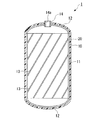
図1に示すように、圧力容器1はアルミニウム合金製のライナー10と、ライナー10の外周に設けられたCFRP(炭素繊維強化樹脂)製の補強層20とから構成されている。
Embodiments of a pressure vessel and a manufacturing method thereof according to the present invention will be described below with reference to the drawings of FIGS. In addition, the pressure vessel in this Example is an aspect as a pressure vessel for high-pressure hydrogen gas filling.
As shown in FIG. 1, the
ライナー10は、円筒状の周壁部材11と、周壁部材11の両端に溶接等の手段により接合された所定曲面形状を有するキャップ状の端部部材12,12とを備えている。周壁部材11の内周面には、周壁部材11の軸線方向に対して斜めに傾斜して延びる突条の補強リブ13が、周方向所定間隔おきに周壁部材11の全長に亘って設けられている。一方の端部部材12の中央には筒状の口金14が貫通しており、溶接等の手段により固定されている。この口金14はガスを充填あるいは放出するためのものであり、その内周面にはバルブ等配管部材取付用のねじ孔14aが形成されている。
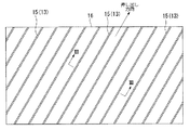
ライナー10は次のようにして製造する。まず、アルミニウム合金を素材として、図3に示すように断面略半円形の突条15を幅方向所定間隔に有する板材16を押し出し成形により製造する。押し出し成形後の板材16の状態では、突条15は板材16の幅方向に所定間隔おきに配置され、互いに平行をなし、押し出し方向に沿って一直線に連続して延びている。
この後、図2に示すように、板材16を押し出し方向に対して所定角度傾斜した状態で、加工すべき周壁部材11の展開寸法に対応する四角形に裁断する。つまり、突条15の延びる方向と裁断後の板材の各辺の延びる方向が互いに傾斜するように裁断する。
The
The
Thereafter, as shown in FIG. 2, the
そして、裁断した板材16を、突条15を有する面を内側にして円筒状に曲げ加工し、突き合わせた両端を溶接等の適宜手段により接合して周壁部材11を形成する。これにより、突条15は周壁部材11の軸線方向に対して斜めに傾斜して延びる補強リブ13となり、補強リブ13を備えた周壁部材11が製造される。
この後、周壁部材11の軸線方向両端部に端部部材12,12を接合してライナー10を形成し、さらにライナー10の外周に補強層20を形成して圧力容器1が完成する。なお、補強層20の形成方法は従来からある一般的な方法と同じであるので説明を省略する。
Then, the
Thereafter, the
このように構成された圧力容器1においては、周壁部材11の内周面に設けられた補強リブ13が周壁部材11の軸線方向に対して斜めに傾斜して延びているので、ライナー10を軸線方向および周方向に補強することができ、等方性を持った補強ができる。したがって、圧力容器1へのガス充填時の内圧変化に対してライナー10の軸線方向および周方向の変形を抑制することができ、ライナー10の薄肉化と疲労強度の向上を両方同時に達成することができる。その結果、ライナー10の軽量化が可能になり、ひいては圧力容器1の軽量化が可能になる。
In the
なお、補強リブ13の断面形状および寸法、補強リブ13のピッチ、周壁部材11の軸線方向に対する補強リブ13の傾斜角度は、圧力容器1の容量、寸法、最大内圧等の条件に応じて適宜設定することができる。また、板材16はプレス成形により形成することも可能である。
The cross-sectional shape and dimensions of the reinforcing
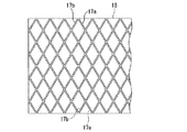
さらに、ライナー10の周壁部材11における補強リブを格子状に設けることも可能である。この場合には、図4に示すように、周壁部材11の軸線方向に対する傾斜方向を異にし互いに交差して延びる突条の補強リブ17a,17bを有する板材18をプレス成形により加工し、この板材18を、補強リブ17a,17bを有する面を内側にして円筒状に曲げ加工し接合して周壁部材11を形成する。この後の製造工程は前述と同じであるので説明を省略する。
このように周壁部材11の内周面に格子状をなすように補強リブ17a,17bを設けると、ライナー10をより強固に補強することができるので、ライナー10の軽量化、圧力容器1の軽量化をさらに促進することができる。
なお、この場合も、補強リブ17a,17bの断面形状および寸法、補強リブ17a,17bのピッチ、周壁部材11の軸線方向に対する補強リブ17a,17bの傾斜角度は、圧力容器1の容量、寸法、最大内圧等の条件に応じて適宜設定することができる。
Further, the reinforcing ribs on the
If the reinforcing
Also in this case, the cross-sectional shape and dimensions of the reinforcing
前述した実施例では、板材を円筒状に曲げ加工し突き合わせ溶接することにより、ライナー10の周壁部材11を製造したが、金属製の筒体を押し出し加工する際に、この筒体の内周面に軸線方向に対して傾斜して延びる突条の補強リブを同時に成形して周壁部材を製造することも可能である。
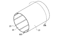
例えば、図5に示すように、金属製の筒体21を押し出し加工する際に、ダイスを用いて筒体21の内周面22に軸線方向に沿って延びる突条の補強リブ23を成形し、この筒体21の押し出し加工直後に筒体21を捻ることによって、内周面22に形成された補強リブ23を筒体21の軸線方向に対して傾斜させる。このような方法によっても、図1に示される周壁部材11と同様の周壁部材を製造することができる。
あるいは、ダイスを用いて内周面に突条の補強リブを軸線方向に沿って成形しながら金属製の筒体を押し出し加工する際に、前記ダイスを筒体に対して所定の回転速度で回転させながら筒体の押し出し加工を行うと、内周面に軸線方向に対して傾斜して延びる突条の補強リブを有する筒体を成形することができる。このような方法によっても、図1に示される周壁部材11と同様の周壁部材を製造することができる。
そして、これら方法によって製造された周壁部材の軸線方向両端部に端部部材を接合することによりライナー10を製造することができる。
In the above-described embodiment, the
For example, as shown in FIG. 5, when the
Alternatively, the die is rotated at a predetermined rotational speed with respect to the cylindrical body when the metal cylindrical body is extruded while forming the reinforcing ribs of the protrusions along the axial direction on the inner peripheral surface using the die. When the cylindrical body is extruded while being formed, a cylindrical body having protruding rib reinforcing ribs extending at an inclination with respect to the axial direction on the inner peripheral surface can be formed. Also by such a method, the surrounding wall member similar to the surrounding
And the
〔他の実施例〕
なお、この発明は前述した実施例に限られるものではない。
例えば、ライナーはアルミニウム合金製に限るものではなく、充填物質の透過を阻止し、且つ、充填物質に対する耐食性を有していれば、他の金属で形成することも可能である。充填物質は水素ガスに限定されるものではなく、CNG他、種々のものが可能である。
また、補強層としては、ライナーの外周に繊維を巻き付けるとともに樹脂で含浸固定してなる繊維強化樹脂が好ましいが、繊維は炭素繊維に限定されるものではなく、ガラス繊維や化学繊維なども採用可能である。
[Other Examples]
The present invention is not limited to the embodiment described above.
For example, the liner is not limited to an aluminum alloy, and may be formed of other metals as long as it prevents the filling material from permeating and has corrosion resistance to the filling material. The filling material is not limited to hydrogen gas, and various materials such as CNG are possible.
The reinforcing layer is preferably a fiber reinforced resin in which fibers are wound around the outer periphery of the liner and impregnated and fixed with a resin. However, the fibers are not limited to carbon fibers, and glass fibers, chemical fibers, and the like can also be used. It is.
1 圧力容器
10 ライナー
11 周壁部材
12 端部部材
13 補強リブ
16,18 板材
17a,17b 補強リブ
20 補強層
21 筒体
22 内周面
23 補強リブ
DESCRIPTION OF
Claims (3)
A peripheral wall member made of a metal cylinder in which the reinforcing ribs of the ridges extend on the inner peripheral surface inclining with respect to the axial direction is formed by extrusion processing, and end members are joined to both axial ends of the peripheral wall member. A method of manufacturing a pressure vessel, characterized in that:
Priority Applications (1)
| Application Number | Priority Date | Filing Date | Title |
|---|---|---|---|
| JP2004108789A JP4263652B2 (en) | 2004-04-01 | 2004-04-01 | Manufacturing method of pressure vessel |
Applications Claiming Priority (1)
| Application Number | Priority Date | Filing Date | Title |
|---|---|---|---|
| JP2004108789A JP4263652B2 (en) | 2004-04-01 | 2004-04-01 | Manufacturing method of pressure vessel |
Publications (2)
| Publication Number | Publication Date |
|---|---|
| JP2005291415A true JP2005291415A (en) | 2005-10-20 |
| JP4263652B2 JP4263652B2 (en) | 2009-05-13 |
Family
ID=35324565
Family Applications (1)
| Application Number | Title | Priority Date | Filing Date |
|---|---|---|---|
| JP2004108789A Expired - Fee Related JP4263652B2 (en) | 2004-04-01 | 2004-04-01 | Manufacturing method of pressure vessel |
Country Status (1)
| Country | Link |
|---|---|
| JP (1) | JP4263652B2 (en) |
Cited By (4)
| Publication number | Priority date | Publication date | Assignee | Title |
|---|---|---|---|---|
| WO2009082189A3 (en) * | 2007-12-21 | 2009-10-29 | Universiti Putra Malaysia | Compressed natural gas composite tank for vehicles |
| CN108000075A (en) * | 2017-12-29 | 2018-05-08 | 合肥久享机械有限责任公司 | A kind of lightweight high-intensity gas receiver and manufacturing technique method |
| JP2018138452A (en) * | 2016-12-12 | 2018-09-06 | ザ・ボーイング・カンパニーThe Boeing Company | Additively manufactured reinforced structure |
| JP2024540412A (en) * | 2021-11-09 | 2024-10-31 | インフィニット コンポジッツ,インコーポレーテッド | Additive Manufacturing Processes for High Performance Composite Pressure Vessels and Structures |
-
2004
- 2004-04-01 JP JP2004108789A patent/JP4263652B2/en not_active Expired - Fee Related
Cited By (6)
| Publication number | Priority date | Publication date | Assignee | Title |
|---|---|---|---|---|
| WO2009082189A3 (en) * | 2007-12-21 | 2009-10-29 | Universiti Putra Malaysia | Compressed natural gas composite tank for vehicles |
| JP2018138452A (en) * | 2016-12-12 | 2018-09-06 | ザ・ボーイング・カンパニーThe Boeing Company | Additively manufactured reinforced structure |
| JP7034648B2 (en) | 2016-12-12 | 2022-03-14 | ザ・ボーイング・カンパニー | Additional manufactured reinforcement structure |
| CN108000075A (en) * | 2017-12-29 | 2018-05-08 | 合肥久享机械有限责任公司 | A kind of lightweight high-intensity gas receiver and manufacturing technique method |
| JP2024540412A (en) * | 2021-11-09 | 2024-10-31 | インフィニット コンポジッツ,インコーポレーテッド | Additive Manufacturing Processes for High Performance Composite Pressure Vessels and Structures |
| JP7876223B2 (en) | 2021-11-09 | 2026-06-19 | インフィニット コンポジッツ,インコーポレーテッド | Additive manufacturing process for high-performance composite pressure vessels and structures |
Also Published As
| Publication number | Publication date |
|---|---|
| JP4263652B2 (en) | 2009-05-13 |
Similar Documents
| Publication | Publication Date | Title |
|---|---|---|
| JP5306553B1 (en) | Pipe joint structure | |
| JP3527737B1 (en) | High-pressure tank using high-rigidity fiber and method for manufacturing the same | |
| JP4436148B2 (en) | Pressure vessel liner and method of manufacturing the same | |
| KR102325236B1 (en) | Threaded bosses for pressure vessels | |
| CN106217915A (en) | The manufacture method of tank | |
| JP2023505037A (en) | High-pressure tank with wound hoop layer and helical layer and method for manufacturing the same | |
| JPH0942595A (en) | Pressure vessel | |
| JP4263652B2 (en) | Manufacturing method of pressure vessel | |
| JP2011094797A (en) | Hose clamp | |
| US6908006B2 (en) | High-pressure tank and method for fabricating the same | |
| US7137526B2 (en) | High-pressure tank and method for fabricating the same | |
| JP2011117525A (en) | Steel pipe concrete composite pipe | |
| JP6475077B2 (en) | Manufacturing method of pressure vessel liner | |
| JP5198681B1 (en) | Strap band device for connection | |
| KR100730575B1 (en) | How to make pipe for rigid reinforcement | |
| US11248745B2 (en) | Reinforcement technology for super-high pressure tank reinforced by carbon fiber | |
| JP2008235209A (en) | An exhaust pipe for a fuel cell vehicle and a manufacturing method thereof. | |
| JP2003287193A (en) | Pressure vessel | |
| JP4473705B2 (en) | Hydroform processing method, hydroform molded article and structure | |
| JP4084573B2 (en) | Pressure vessel mirror part wrap part molding method | |
| JP7093240B2 (en) | High pressure tank | |
| JP2005321093A (en) | Manufacturing method of liner for pressure container | |
| JP4198095B2 (en) | Pressure vessel liner and method of manufacturing the same | |
| JP2006336839A (en) | Pressure vessel | |
| JP5495158B2 (en) | Steel pipe concrete composite pipe |
Legal Events
| Date | Code | Title | Description |
|---|---|---|---|
| A621 | Written request for application examination |
Free format text: JAPANESE INTERMEDIATE CODE: A621 Effective date: 20061222 |
|
| A977 | Report on retrieval |
Free format text: JAPANESE INTERMEDIATE CODE: A971007 Effective date: 20080408 |
|
| A131 | Notification of reasons for refusal |
Free format text: JAPANESE INTERMEDIATE CODE: A131 Effective date: 20080507 |
|
| A521 | Written amendment |
Free format text: JAPANESE INTERMEDIATE CODE: A523 Effective date: 20080701 |
|
| TRDD | Decision of grant or rejection written | ||
| A01 | Written decision to grant a patent or to grant a registration (utility model) |
Free format text: JAPANESE INTERMEDIATE CODE: A01 Effective date: 20090203 |
|
| A01 | Written decision to grant a patent or to grant a registration (utility model) |
Free format text: JAPANESE INTERMEDIATE CODE: A01 |
|
| A61 | First payment of annual fees (during grant procedure) |
Free format text: JAPANESE INTERMEDIATE CODE: A61 Effective date: 20090212 |
|
| FPAY | Renewal fee payment (event date is renewal date of database) |
Free format text: PAYMENT UNTIL: 20120220 Year of fee payment: 3 |
|
| R150 | Certificate of patent or registration of utility model |
Ref document number: 4263652 Country of ref document: JP Free format text: JAPANESE INTERMEDIATE CODE: R150 Free format text: JAPANESE INTERMEDIATE CODE: R150 |
|
| FPAY | Renewal fee payment (event date is renewal date of database) |
Free format text: PAYMENT UNTIL: 20130220 Year of fee payment: 4 |
|
| R250 | Receipt of annual fees |
Free format text: JAPANESE INTERMEDIATE CODE: R250 |
|
| FPAY | Renewal fee payment (event date is renewal date of database) |
Free format text: PAYMENT UNTIL: 20130220 Year of fee payment: 4 |
|
| FPAY | Renewal fee payment (event date is renewal date of database) |
Free format text: PAYMENT UNTIL: 20140220 Year of fee payment: 5 |
|
| R250 | Receipt of annual fees |
Free format text: JAPANESE INTERMEDIATE CODE: R250 |
|
| R250 | Receipt of annual fees |
Free format text: JAPANESE INTERMEDIATE CODE: R250 |
|
| R250 | Receipt of annual fees |
Free format text: JAPANESE INTERMEDIATE CODE: R250 |
|
| R250 | Receipt of annual fees |
Free format text: JAPANESE INTERMEDIATE CODE: R250 |
|
| R250 | Receipt of annual fees |
Free format text: JAPANESE INTERMEDIATE CODE: R250 |
|
| R250 | Receipt of annual fees |
Free format text: JAPANESE INTERMEDIATE CODE: R250 |
|
| R250 | Receipt of annual fees |
Free format text: JAPANESE INTERMEDIATE CODE: R250 |
|
| R250 | Receipt of annual fees |
Free format text: JAPANESE INTERMEDIATE CODE: R250 |
|
| LAPS | Cancellation because of no payment of annual fees |