JP2005291403A - Variable pulley device - Google Patents
Variable pulley device Download PDFInfo
- Publication number
- JP2005291403A JP2005291403A JP2004108410A JP2004108410A JP2005291403A JP 2005291403 A JP2005291403 A JP 2005291403A JP 2004108410 A JP2004108410 A JP 2004108410A JP 2004108410 A JP2004108410 A JP 2004108410A JP 2005291403 A JP2005291403 A JP 2005291403A
- Authority
- JP
- Japan
- Prior art keywords
- movable
- pulley
- movable pulley
- shaft
- coil spring
- Prior art date
- Legal status (The legal status is an assumption and is not a legal conclusion. Google has not performed a legal analysis and makes no representation as to the accuracy of the status listed.)
- Pending
Links
Images
Classifications
-
- F—MECHANICAL ENGINEERING; LIGHTING; HEATING; WEAPONS; BLASTING
- F16—ENGINEERING ELEMENTS AND UNITS; GENERAL MEASURES FOR PRODUCING AND MAINTAINING EFFECTIVE FUNCTIONING OF MACHINES OR INSTALLATIONS; THERMAL INSULATION IN GENERAL
- F16H—GEARING
- F16H57/00—General details of gearing
- F16H57/04—Features relating to lubrication or cooling or heating
- F16H57/048—Type of gearings to be lubricated, cooled or heated
- F16H57/0487—Friction gearings
- F16H57/0489—Friction gearings with endless flexible members, e.g. belt CVTs
Landscapes
- Engineering & Computer Science (AREA)
- General Engineering & Computer Science (AREA)
- Mechanical Engineering (AREA)
- General Details Of Gearings (AREA)
- Pulleys (AREA)
- Transmissions By Endless Flexible Members (AREA)
Abstract
Description
本発明は、可変プーリの固定プーリ半体と可動プーリ半体との可動部における潤滑剤の外部への漏れ及び外部からの埃塵の侵入を防止するとともに耐久性を有し、その構造を簡単にして加工箇所を少なくすることができる可変プーリ装置に関する。 The present invention prevents the leakage of lubricant to the outside and the intrusion of dust from the outside in the movable part of the fixed pulley half and the movable pulley half of the variable pulley, and has durability and simple structure. The present invention relates to a variable pulley device that can reduce the number of machining points.
従来技術として、無段変速機において、駆動軸と従動軸にそれぞれ固定プーリ半体と、これに対し進退移動し得る可動プーリ半体とよりなる伝動プーリを設け、駆動軸および従動軸上の伝動プーリ間に無端Vベルトを掛回し、駆動軸および従動軸上の可動プーリ半体を移動調整して駆動軸の回転と従動軸の回転を無段に変速させて従動軸に伝達するようにした無段変速機が存在する。かかる変速機では、その運転中は可動プーリ半体は固定プーリ半体に対して絶えず進退移動調整されるので、常に円滑,軽快な無段変速を行うには、可動プーリ半体の被潤滑部に常に、有効に潤滑油もしくはグリスを供給することが望まれる。 As a conventional technique, in a continuously variable transmission, a drive pulley and a driven shaft are each provided with a transmission pulley consisting of a fixed pulley half and a movable pulley half capable of moving forward and backward, and transmission on the drive shaft and the driven shaft. An endless V-belt is hung between the pulleys, and the movable pulley half on the drive shaft and the driven shaft is moved and adjusted so that the rotation of the drive shaft and the rotation of the driven shaft are continuously variable and transmitted to the driven shaft. There is a continuously variable transmission. In such a transmission, during operation, the movable pulley half is continuously adjusted to move forward and backward with respect to the fixed pulley half. Therefore, in order to always perform smooth and light continuously variable transmission, the lubricated portion of the movable pulley half It is always desirable to effectively supply lubricating oil or grease.
この種のものとして、下記特許文献1(特開昭63−190962号の公報)に開示されているように、固定側プーリ軸と可動側プーリ軸の軸問および可動側プーリ軸と外筒間にある潤滑油(グリス)の洩れを、可動側プーリ軸両端のオイルシール(固定側プーリ軸と可動側プーリ軸の軸間)と、可動側プーリ軸の外周の端部にあるOリング(可動側プーリ軸と外筒間)と、可動プーリ半体と外筒のフランジ部間のガスケットによって防止しており、外筒のフランジ部をコイルばねによって押圧することで、フランジ部のガスケットのシール性を向上させようとするものである。
上記の特許文献1では、外筒のフランジ部と駆動プレート間にコイルバネが縮設され、外筒間にある潤滑油(グリス)の洩れを、可動側プーリ軸両端のオイルシール(固定側プーリ軸と軸間)と、可動側プーリ軸の外周の端部にあるOリング(可動側プーリ軸と外筒間)と、可動プーリ半体と外筒のフランジ部間のガスケットによって防止している。そして、前記外筒のフランジ部をコイルバネによって押圧し、ガスケットを圧縮させてシール性を向上させている。 In the above-mentioned patent document 1, a coil spring is contracted between the flange portion of the outer cylinder and the drive plate, and leakage of lubricating oil (grease) between the outer cylinders causes oil seals (fixed-side pulley shafts) at both ends of the movable pulley shaft. And between the shaft), an O-ring (between the movable pulley shaft and the outer cylinder) at the outer peripheral end of the movable pulley shaft, and a gasket between the movable pulley half and the flange portion of the outer cylinder. And the flange part of the said outer cylinder is pressed with a coil spring, the gasket is compressed, and the sealing performance is improved.
すなわち、可動プーリ半体と外筒のフランジ部間に挟装されるOリングをガスケットに置き換えて、シールすることにより、シール性の向上及び加工箇所の減少という効果を得ようとしたものである。しかしながら、そのコイルバネは、バネ力によって押圧する方向(軸方向)の荷重と、可動プーリ半体の回転によって発生する遠心力とによって、コイルバネ自体を直径方向外方に拡がるように移動する力が発生する。それによってコイルバネが位置ズレを起こし、可動プーリ半体に加わるバネ力が弱くなり、その結果、性能として変速時のフイーリングが悪化してしまうおそれがある。 In other words, the O-ring sandwiched between the movable pulley half and the flange portion of the outer cylinder is replaced with a gasket and sealed, thereby obtaining the effect of improving the sealing performance and reducing the number of processed parts. . However, the coil spring generates a force that moves the coil spring to expand outward in the diametrical direction due to the load in the direction pressed by the spring force (axial direction) and the centrifugal force generated by the rotation of the movable pulley half. To do. As a result, the coil spring is displaced, and the spring force applied to the movable pulley half is weakened. As a result, there is a possibility that the feeling during shifting is deteriorated as a performance.
また、前記コイルバネと、外筒のフランジ部とを介してガスケットを可動プーリ半体に押圧しているので、その押圧力が直接ガスケット全体に負荷として加わりガスケットに悪影響を及ぼすものである。さらに、コイルバネの位置ズレに伴う負荷の変動がガスケットにさらなる劣化を促進させるものである。これらのことから、ガスケットのシール性能の低下及び寿命が短くなるといった問題がある。本発明の技術的課題(目的)は、可変プーリ装置において、可変プーリの固定プーリ半体と可動プーリ半体との可動部における潤滑剤のシール構造を簡単なものとするとともに耐久性のあるものとすることにある。 Further, since the gasket is pressed against the movable pulley half through the coil spring and the flange portion of the outer cylinder, the pressing force is directly applied to the entire gasket as a load, which adversely affects the gasket. Furthermore, the load fluctuation accompanying the displacement of the coil spring promotes further deterioration of the gasket. For these reasons, there is a problem that the sealing performance of the gasket is lowered and the life is shortened. The technical problem (objective) of the present invention is that the structure of the lubricant in the movable part of the fixed pulley half and the movable pulley half of the variable pulley is simplified and durable in the variable pulley device. It is to do.
そこで発明者は、上記課題を解決すべく、鋭意,研究を重ねた結果、本発明を、外周面にガイドピンが装着された固定側プーリ軸の軸方向端部に固定側プーリフェースが設けられてなる固定プーリ半体と、前記ガイドピンが遊挿するガイド長孔を有し,可動側プーリ軸の軸方向端部に可動側プーリフェースが設けられてなる可動プーリ半体と、鍔状部と該鍔状部の外側面に形成された環状溝部とを有し,且つ前記可動側プーリ軸の外周面を覆う外筒と、Oリングと、前記外筒の軸方向に沿って配置されるコイルバネとからなり、前記Oリングが前記環状溝部に収納されるとともに、前記鍔状部が前記可動側プーリーフェースの可動ボス部裏面側付近に当接され、前記鍔状部が前記コイルバネにより前記可動ボス部側に弾性付勢されてなる可変プーリ装置としたことにより、上記課題を解決したものである。 Therefore, the inventor has intensively studied to solve the above problems, and as a result, the present invention is provided with a fixed pulley face at the axial end portion of the fixed pulley shaft having a guide pin mounted on the outer peripheral surface. A movable pulley half having a guide pulley through which the guide pin is loosely inserted, a movable pulley face provided with a movable pulley face at an axial end of the movable pulley shaft, and a bowl-shaped portion And an annular groove formed on the outer surface of the flange-shaped portion, and an outer cylinder that covers the outer peripheral surface of the movable pulley shaft, an O-ring, and an axial direction of the outer cylinder. A coil spring, the O-ring is housed in the annular groove, the hook-shaped portion is brought into contact with the movable boss portion near the back side of the movable pulley face, and the hook-shaped portion is moved by the coil spring. Variable, elastically biased toward the boss By was over Li device is obtained by solving the above problems.
さらに、上述の構成において、前記鍔状部9bの外周端縁には、鍔状部9b面に略直交する周状折曲片が形成されてなる可変プーリ装置としたり、前記環状溝部は、前記コイルバネ14の外周に配置してなる可変プーリ装置としたことにより、上記課題を解決したものである。
Furthermore, in the above-described configuration, a circumferential pulley piece that is substantially orthogonal to the surface of the flange 9b is formed on the outer peripheral edge of the flange 9b. The variable pulley device arranged on the outer periphery of the
請求項1の発明によれば、鍔状部に形成された環状溝部内にOリングを収納して、その鍔状部をコイルバネにより可動プーリ半体の可動ボス部に弾性付勢しているので、Oリングが鍔状部及び可動ボス部の両面に密接に接触することができ、シール性を向上させることができる。また、Oリングのための溝加工を受ける必要性が無いため、その分可動側プーリ軸の軸方向長さを短くする事ができ、製品自体のコンパクト化が図れ、軽量化できる。さらに、外筒の鍔状部によって、長孔近傍を油密に被覆する機能と、コイルバネのばね座又は案内ガイドとしての2つの機能が得られるため、部品点数を少なくすることができ、製品自体のコストダウンが図れる。 According to the first aspect of the present invention, the O-ring is accommodated in the annular groove formed in the hook-shaped portion, and the hook-shaped portion is elastically biased to the movable boss portion of the movable pulley half by the coil spring. The O-ring can be brought into close contact with both surfaces of the bowl-shaped portion and the movable boss portion, and the sealing performance can be improved. In addition, since there is no need to receive a groove for the O-ring, the axial length of the movable pulley shaft can be shortened accordingly, and the product itself can be made compact and light. In addition, since the flange-shaped part of the outer cylinder provides two functions, ie, a function of oil-tightly covering the vicinity of the long hole and a spring seat or guide guide for the coil spring, the number of parts can be reduced, and the product itself Cost reduction.
請求項2の発明によれば、鍔状部の周状折曲片をボス外径に略等しくして覆うことにより、鍔状部と可動ボス部との接合状態を極めて安定した状態にすることができる。請求項3の発明によれば、コイルバネは鍔状部の背面側で且つ前記環状溝部箇所に囲まれることにより、コイルバネを直径方向に安定した状態で支持することができる。よって、コイルバネが外筒の鍔状部の環状溝部の円周膨出形状によって、良好に保持することができ、製品としての信頼性が向上できる。
According to the invention of
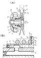
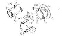
以下、本発明を図面に基づいて説明する。図1は、本発明における従動プーリ機構を示したものである。その従動プーリAは、図1(A),(B)に示すように、固定プーリ半体A1 と可動プーリ半体A2 とから構成される。その固定プーリ半体A1は、図2,図3(A)等に示すように、中空状の固定側プーリ軸1と、扁平円錐状の固定側プーリフェース3とが形成されている。その固定側プーリ軸1の外周側面の所定箇所には、ガイドピン2が装着されている。
Hereinafter, the present invention will be described with reference to the drawings. FIG. 1 shows a driven pulley mechanism according to the present invention. The driven pulley A is composed of a fixed pulley half A 1 and a movable pulley half A 2 as shown in FIGS. As shown in FIGS. 2 and 3A, the fixed pulley half A 1 is formed with a hollow fixed pulley shaft 1 and a flat conical fixed pulley face 3. A
該ガイドピン2は、円筒状に形成され、前記固定側プーリ軸1の所定箇所に圧入されている。可動プーリ半体A2 は、図2,図3(B)等に示すように、中空状の可動側プーリ軸5,ガイド長孔6と扁平円錐状の可動側プーリフェース7から構成される。その可動側プーリ軸5の軸方向の端部の端面には、その内周面側に沿って周状凹部5aが形成されている。該周状凹部5aは、周方向に直交する断面が略方形状に形成されたものであり、オイルシール12が挿入固着されるようになっている。
The
その固定プーリ半体A1の固定側プーリ軸1は、図1(A)に示すように、遠心クラッチBとの間に設けられた従動軸10に回動自在に支承されている。ニードルベアリング及びボールベアリング等の軸受11を介してこの固定プーリ半体A1の固定側プーリ軸1の外周に前記可動プーリ半体A2 の可動側プーリ軸5が摺動自在に装着されている。そして、固定プーリ半体A1と可動プーリ半体A2 における固定側プーリフェース3と可動側プーリフェース7とが相対向して、無端Vベルト23が掛けられる。
The stationary pulley shaft 1 of the stationary pulley half A 1 is rotatably supported by a driven shaft 10 provided between the stationary pulley shaft 1 and the centrifugal clutch B, as shown in FIG. The
その固定プーリ半体A1と可動プーリ半体A2 とからなる従動プーリAは、図示しない駆動側プーリと対をなす。前記ガイド長孔6には、図1に示すように、前記固定側プーリ軸1に装着されたガイドピン2が挿入される。このガイドピン2は、図1(B)に示すように、回転自在なガイドローラ2aが装着されており、前記可動側プーリ軸5はガイド長孔6と、前記ガイドピン2の係合によって案内され、前記固定側プーリ軸1と可動側プーリ軸5とが相互に周方向に回動することなく、軸方向に沿って相互に摺動動作が行なえるようになっている。その可動側プーリ軸5の外周には、外筒9を装着される。
The driven pulley A composed of the fixed pulley half A 1 and the movable pulley half A 2 makes a pair with a driving pulley (not shown). As shown in FIG. 1, a
そして、前記可動プーリ半体A2 の可動側プーリフェース7の可動ボス部7aの裏面側と、前記駆動プレート20との間にはコイルバネ14が配置されている。そのコイルバネ14は、前記外筒9の外周側に配置され、そのコイルバネ14の長手方向一端側が前記駆動プレート20に当接し、また、コイルバネ14の長手方向他端側が外筒9の鍔状部9bに当接して、その鍔状部9bを介して前記可動側プーリフェース7の裏面側を固定プーリ半体A1の固着側プーリフェース3に接近するように弾性的付勢している〔図1(A),(B)参照〕。
A
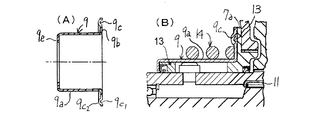
その外筒9は、円筒部9aと鍔状部9bとから構成されている。その円筒部9aには、前記可動プーリ半体A2 の可動側プーリ軸5が挿入されるものであって、円筒部9aの内径は、可動側プーリ軸5が円滑に入り込むことができる程度である。前記可動側プーリ軸5の外周を円筒部9aにて覆われることにより、前記ガイド長孔6は周囲が略閉鎖状となった空隙部を構成する。この空隙部は、潤滑油貯留室S1 となり、前記ガイド長孔6に充填されたグリース等の潤滑剤が外部に漏れないように溜めておくことができるようになっている。その鍔状部9bは、略円板状に形成されたものである。その直径は、前記可動ボス部7aの外径に略等しく形成されたものである。
The
その鍔状部9bには、図1(B),図2,図3(C)に示すように、環状溝部9cが形成されている。該環状溝部9cは、前記鍔状部9bの表面側9b1 より裏面側9b2 に向かって凹むようにして形成されたものである。すなわち、その環状溝部9cは、鍔状部9bの正面側では凹み状であり、鍔状部9bの裏面側では突出状となっている。ここで、前記環状溝部9cは、鍔状部9bの表面側9b1 において凹面側9c1 と称し、鍔状部9bの裏面側9b2 においては凸面側9c2 と称する。
As shown in FIGS. 1B, 2 and 3C, an
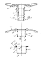
その環状溝部9cの凹面側9c1 には、図1(B),図5(A),(B)等に示すように、Oリング13が収納されるようになっている。その環状溝部9cの深さは、Oリング13の一部は環状溝部9cから突出するようになっおり、鍔状部9bと可動プーリ半体A2 の可動ボス部7aの背面側に当接した状態で、Oリング13が圧力を受けて変形して、適正にシール状態となるようになっている。また、前記凸面側9c2 は、円周膨出形状となっており、その円周膨出形状とした凸面側9c2 によって、前記コイルバネ14の軸方向端部のバネ外径が囲まれるようにして支持されるようになっている。
As shown in FIG. 1B, FIG. 5A, FIG. 5B, etc., an O-
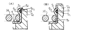
すなわち、前記環状溝部9cの内周側の直径を前記コイルバネ14の外径と略同一とすることにより、コイルバネ14の軸方向端部は、環状溝部9cの円周膨出形状とした凸面側9c2 によって、それぞれの径が略一致した状態で保持されることとなり、コイルバネ14が鍔状部9bによって極めて安定した状態に保持されることができるものである。その鍔状部9bにおいて、前記環状溝部9cが形成されたさらに外周には周状折曲片9dが形成されている。その周状折曲片9dは、前記鍔状部9bの表面側9b1 に突出するようにして形成されたものであり、周状折曲片9dは前記鍔状部9bに対して略直角に折曲形成されたものである。該周状折曲片9dの内径は、僅かの隙間を有する程度以下で、前記可動ボス部7aの外径が挿入可能とした大きさである。
That is, by making the diameter of the inner peripheral side of the
この周状折曲片9dは、鍔状部9bが可動ボス部7aに当接した状態で、周状折曲片9dが可動ボス部7aの外周箇所に係合することにより、鍔状部9bの可動ボス部7aへの当接状態を極めて安定させることができる。前記コイルバネ14は、前述したように、可動側プーリフェース7の可動ボス部7aの裏面側と、前記駆動プレート20との間に配置され、そのコイルバネ14の軸方向端部が外筒9の鍔状部9bに当接して、その鍔状部9bを介して前記可動側プーリフェース7の可動ボス部7aの裏面側に当接させている。
The circumferential bent piece 9d is engaged with the outer peripheral portion of the
そして、前記環状溝部9cに収納されたOリング13が鍔状部9bと可動ボス部7aの間でシールを行なうものである。したがって、Oリング13は、鍔状部9bに形成された環状溝部9cに収納された状態であるために、プーリが駆動状態において前記外筒9が振動しても、Oリング13は鍔状部9bの所定位置に保持され、Oリング13には位置ズレが生じない。また、前記環状溝部9cが鍔状部9bの外周端縁に形成されず、外周端縁よりも少し中心側寄りに形成されることもある〔図4(A),(B)参照〕。
The O-
また、環状溝部9cの外周側から直ぐに周状折曲片9dが形成されたり〔図5(A)参照〕、或いは環状溝部9cの外周側から少し間隔をおいて周状折曲片9dが形成されることももある〔図5(B)参照〕。また、外筒9の軸方向端部には、円筒部9aの内径中心部側に向かって折曲されて折曲部9eが形成されることがある(図1、図3等参照)。該折曲部9eは、可動プーリ半体A2 の可動側プーリ軸5の軸端部に装着されたオイルシールの外側面を覆って、外部の埃塵を除去したり、或いは内部潤滑油の漏れを防止するものである。
Further, a circumferential bent piece 9d is formed immediately from the outer peripheral side of the
また、前記可動側プーリ軸5の軸方向中間部には断面凹状の潤滑油溜6が形成され、この潤滑油溜は固定側プーリ軸1に穿設した連通孔1aを介して、固定側プーリ軸1と前記従動軸10との間に形成された空隙部となる潤滑油貯留室S2 に連通されている。その鍔状部9bは、後述するコイルバネ14からの弾発力を受けるためのばね座として使用される部位である。その鍔状部9bは、前記可動プーリ半体A2 の可動側プーリフェース7の背面側(Vベルトと接触する面とは反対側となる側)に当接し、前記コイルバネ14の弾性力を伝達するものである。
Further, a lubricating
潤滑油貯留室S2 内の潤滑油(グリス)は、ニードルベアリング,ボールベアリング等の軸受11に給油されるとともに、従動側プーリの回転による遠心力をうけて連通孔1aを通って潤滑油貯留室S2 に圧送され、そこに貯留された潤滑油が固定側プーリ軸1,可動側プーリ軸5間のガイドピン2とガイド長孔6との係合箇所に送り込まれ、潤滑させ、可動プーリ半体A2 を常に円滑に移動させることができる。
Lubricating oil (grease) in the lubricating oil storage chamber S 2 is supplied to the bearing 11 such as a needle bearing and a ball bearing, and receives the centrifugal force due to the rotation of the driven pulley and stores the lubricating oil through the communication hole 1a. Lubricating oil that is pumped into the chamber S 2 and stored therein is fed into the engagement portion between the
前記従動プーリAには、図1(A)に示すように、乾式摩擦遠心クラッチBが隣接して配置されている。その従動プーリAの固定側プーリ軸1の左端には、この遠心クラッチB1構成する駆動プレート20が固着されており、無端Vベルト23によって固定プーリ半体A1に伝達された回転力は、前記固定側プーリ軸1を通じて前記駆動プレート20に伝えられる。次いで、遠心ウェイト21およびクラッチアウタ22を経て前記従動軸10に伝達される。
As shown in FIG. 1A, a dry friction centrifugal clutch B is disposed adjacent to the driven pulley A. The
無段変速機の遠心クラッチBの前方には、図示しない駆動プーリが設けられており、駆動側プーリも前記従動プーリAと同様に固定プーリ半体と可動プーリ半体とから構成されている。そして、その駆動プーリ半体と従動プーリとの間に無端Vベルト23が掛け渡され、エンジン回転数に応じて駆動側の可動プーリ半体が遠心力により軸線方向に移動することにより、駆動側における固定側プーリフェースと可動側プーリフェースに巻き掛かられている領域の無端Vベルト23の半径が変化し、これに応じて従動プーリAにおける無端Vベルト23の巻きかけられている領域の半径も変化する。こにれよって、エンジン出力軸の回転数が自動的にかつ無段的に変速されて、従動プーリAに伝えられる。
A driving pulley (not shown) is provided in front of the centrifugal clutch B of the continuously variable transmission, and the driving pulley is composed of a fixed pulley half and a movable pulley half in the same manner as the driven pulley A. Then, an endless V-
本発明は、上記のような構成にすることによって、可動側プーリ軸5の軸方向のOリング13の溝加工箇所が1箇所で済むことから、溝加工に必要なスペースを低減し、その分だけ可動側プーリ軸5の軸方向長さを短くすることができ、製品自体のコンパクト化が図れ、軽量化できる。また、従来と比べ、Oリング13の溝加工箇所が削減できるので、製造コストを抑えることができる。さらに外筒9の鍔状部9bに形成された環状溝部9cは、それ自体がコイルバネ14の軸端部を保持するばね座又は案内ガイドの役目をなすため、コイルバネ14のためのガイド部材を新たに設ける必要性がなく、部品数を減少させることができ、製品自体のコストダウンができるものである。
In the present invention, since the grooved portion of the O-
A…従動プーリ、A1 …固定プーリ半体、A2 …可動プーリ半体、
1…固定側プーリ軸、1a…連通孔、2…ガイドピン、3…固定側プーリフェース、
5…可動側プーリ軸、5a…周状凹部、6…ガイド長孔、7…可動側プーリフェース、
9…外筒、9c…段差部、9d…折曲部、9d1 …接続用円筒部、12…オイルシール、12a…リップ部。
A ... driven pulley, A 1 ... fixed pulley half, A 2 ... movable pulley half,
DESCRIPTION OF SYMBOLS 1 ... Fixed side pulley shaft, 1a ... Communication hole, 2 ... Guide pin, 3 ... Fixed side pulley face,
5 ... movable pulley shaft, 5a ... circumferential recess, 6 ... guide slot, 7 ... movable pulley face,
9 ... outer cylinder, 9c ... stepped portion, 9d ... folded portion, 9d 1 ... connecting cylindrical part, 12 ... oil seal, 12a ... lip.
Claims (3)
Priority Applications (1)
| Application Number | Priority Date | Filing Date | Title |
|---|---|---|---|
| JP2004108410A JP2005291403A (en) | 2004-03-31 | 2004-03-31 | Variable pulley device |
Applications Claiming Priority (1)
| Application Number | Priority Date | Filing Date | Title |
|---|---|---|---|
| JP2004108410A JP2005291403A (en) | 2004-03-31 | 2004-03-31 | Variable pulley device |
Publications (1)
| Publication Number | Publication Date |
|---|---|
| JP2005291403A true JP2005291403A (en) | 2005-10-20 |
Family
ID=35324555
Family Applications (1)
| Application Number | Title | Priority Date | Filing Date |
|---|---|---|---|
| JP2004108410A Pending JP2005291403A (en) | 2004-03-31 | 2004-03-31 | Variable pulley device |
Country Status (1)
| Country | Link |
|---|---|
| JP (1) | JP2005291403A (en) |
Cited By (1)
| Publication number | Priority date | Publication date | Assignee | Title |
|---|---|---|---|---|
| CN119079009A (en) * | 2024-11-08 | 2024-12-06 | 浙江新霸科技有限公司 | Speed changing system of a scooter |
-
2004
- 2004-03-31 JP JP2004108410A patent/JP2005291403A/en active Pending
Cited By (1)
| Publication number | Priority date | Publication date | Assignee | Title |
|---|---|---|---|---|
| CN119079009A (en) * | 2024-11-08 | 2024-12-06 | 浙江新霸科技有限公司 | Speed changing system of a scooter |
Similar Documents
| Publication | Publication Date | Title |
|---|---|---|
| JP5401821B2 (en) | Starting device | |
| JP2013527401A (en) | Decoupler assembly having sliding interface between hub and pulley | |
| JP3934348B2 (en) | Seal ring | |
| JP4948968B2 (en) | Planetary roller type transmission | |
| JP4511230B2 (en) | Variable pulley device | |
| JPH10213207A (en) | Pulley with built-in roller clutch | |
| JP4306032B2 (en) | Pulley device with built-in one-way clutch for alternator | |
| JP2007218414A (en) | Bearing seal structure for belt type automatic transmission | |
| JP2002070972A (en) | Friction roller type transmission | |
| JP4560894B2 (en) | Friction roller type transmission | |
| JP2001208154A (en) | Friction roller type transmission with clutch mechanism | |
| JP2005291401A (en) | Variable pulley device | |
| JP2005273782A (en) | Piston for automatic transmission | |
| JP2012172790A (en) | Pulley device with built-in one-way clutch | |
| JP4494086B2 (en) | One-way clutch | |
| JP2004036798A (en) | Friction roller type transmission | |
| JPS622349Y2 (en) | ||
| JP4513246B2 (en) | Friction roller transmission and friction roller transmission with motor | |
| JP2001336591A (en) | Friction roller type transmission | |
| JP2001336592A (en) | Friction roller type transmission with clutch mechanism | |
| JP2576598Y2 (en) | Flywheel | |
| JPS60252858A (en) | V-belt stepless speed change gear | |
| JPH11148549A (en) | Pulley with built-in roller clutch | |
| JP2005337378A (en) | Power transmission | |
| JP6066619B2 (en) | Torque limiter |