JP2005291402A - Variable pulley device - Google Patents
Variable pulley device Download PDFInfo
- Publication number
- JP2005291402A JP2005291402A JP2004108406A JP2004108406A JP2005291402A JP 2005291402 A JP2005291402 A JP 2005291402A JP 2004108406 A JP2004108406 A JP 2004108406A JP 2004108406 A JP2004108406 A JP 2004108406A JP 2005291402 A JP2005291402 A JP 2005291402A
- Authority
- JP
- Japan
- Prior art keywords
- movable pulley
- pulley
- shaft
- outer cylinder
- movable
- Prior art date
- Legal status (The legal status is an assumption and is not a legal conclusion. Google has not performed a legal analysis and makes no representation as to the accuracy of the status listed.)
- Granted
Links
- 230000002093 peripheral effect Effects 0.000 claims abstract description 22
- 239000000463 material Substances 0.000 claims description 2
- 239000000428 dust Substances 0.000 abstract description 9
- 239000000314 lubricant Substances 0.000 abstract description 4
- 239000003921 oil Substances 0.000 description 27
- 239000010687 lubricating oil Substances 0.000 description 23
- 230000005540 biological transmission Effects 0.000 description 7
- 238000003860 storage Methods 0.000 description 7
- 239000004519 grease Substances 0.000 description 6
- 238000005452 bending Methods 0.000 description 4
- 238000004891 communication Methods 0.000 description 3
- 230000004888 barrier function Effects 0.000 description 2
- 230000008859 change Effects 0.000 description 2
- 238000004519 manufacturing process Methods 0.000 description 2
- 230000007246 mechanism Effects 0.000 description 2
- 238000000034 method Methods 0.000 description 2
- 230000008569 process Effects 0.000 description 2
- 230000002787 reinforcement Effects 0.000 description 2
- 230000009471 action Effects 0.000 description 1
- 230000032683 aging Effects 0.000 description 1
- 238000013459 approach Methods 0.000 description 1
- 238000007796 conventional method Methods 0.000 description 1
- 230000006866 deterioration Effects 0.000 description 1
- 230000000694 effects Effects 0.000 description 1
- 238000012545 processing Methods 0.000 description 1
- 238000007789 sealing Methods 0.000 description 1
- 238000003466 welding Methods 0.000 description 1
Images
Landscapes
- Transmissions By Endless Flexible Members (AREA)
- General Details Of Gearings (AREA)
- Sealing With Elastic Sealing Lips (AREA)
- Pulleys (AREA)
Abstract
Description
本発明は、可変プーリの固定プーリ半体と可動プーリ半体との可動部における潤滑剤の外部への漏れ及び外部からの埃塵の侵入を防止するとともに、耐久性を有し且つ部品点数を減少させ、構造を極めて簡単なものとした可変プーリ装置に関する。 The present invention prevents the lubricant from leaking to the outside and the intrusion of dust from the outside in the movable part of the fixed pulley half and the movable pulley half of the variable pulley, has durability and reduces the number of parts. The present invention relates to a variable pulley apparatus that is reduced and has a very simple structure.
従来より、通常の前進走行時におけるエンジン等の動力源の回転速度の変化により、カム機構が作動し、そのプーリに巻掛けられているベルト駆動径を適宜,無段に可変させて変速する無段変速プーリ装置が存在している。この無段変速機において、駆動軸と従動軸にそれぞれ固定プーリ半体と、該固定プーリ半体に対し進退移動し得る可動プーリ半体とよりなる伝動プーリを設け、駆動軸および従動軸上の伝動プーリ間に無端Vベルトを掛回し、駆動軸および従動軸上の可動プーリ半体を移動調整して駆動軸の回転と従動軸の回転を無段に変速させて従動軸に伝達するようにした無段変速機が存在している。かかる変速機では、その運転中において、前記可動プーリ半体は固定プーリ半体に対して絶えず進退移動により、両間隔が調整されるので、前記可動プーリ半体が常に円滑、軽快な無段変速を行うには可動プーリ半体の被潤滑部に常に、有効に潤滑油もしくはグリスを供給することが望まれる。
従来の技術として特許文献1(実公昭61−605号)に開示されているように、固定プーリ半体と一体構成とした固定側プーリ軸を回転軸外周に回転自在に支承し、この固定側プーリ軸上に可動プーリ半体と一体構成の可動側プーリ軸を軸方向に摺動自在とした構成となっている。 As disclosed in Patent Document 1 (Japanese Utility Model Publication No. 61-605) as a conventional technique, a fixed pulley shaft integrally formed with a fixed pulley half is rotatably supported on the outer periphery of a rotating shaft. A movable pulley shaft that is integrated with the movable pulley half on the pulley shaft is configured to be slidable in the axial direction.
その可動側プーリ軸の軸方向両端部には、オイルシールが設けられ、そのシール面が固定側プーリ軸の外周面に摺接している。さらに、前記可動側プーリ軸の内周面には断面凹状の通油溝を形成し、この通油溝と、固定側プーリ軸の外周面とにより潤滑油溜を形成し、かつ通油溝の底面をオイルシールのシール面よりも径方向外方に位置させている。これによって、可動側プーリ軸の回転による遠心力を利用して潤滑油溜内に潤滑油を貯留させて、余分な潤滑油がオイルシールに供給され、その結果シール性がよくなり、潤滑油の、固定および可動側プーリ軸聞からの洩れを有効に防止することができる。 Oil seals are provided at both axial ends of the movable pulley shaft, and the seal surfaces are in sliding contact with the outer peripheral surface of the fixed pulley shaft. Further, an oil passage groove having a concave cross section is formed on the inner peripheral surface of the movable pulley shaft, and a lubricating oil reservoir is formed by the oil passage groove and the outer peripheral surface of the fixed pulley shaft. The bottom surface is positioned radially outward from the seal surface of the oil seal. As a result, the centrifugal force generated by the rotation of the movable pulley shaft is used to store the lubricating oil in the lubricating oil reservoir, so that the excess lubricating oil is supplied to the oil seal. Thus, leakage from the fixed and movable pulley shafts can be effectively prevented.
上記の特許文献1においては、固定側プーリ軸と可動側プーリ軸の軸間および可動側プーリ軸と外筒間にある潤滑油(グリス)の洩れを、可動側プーリ軸両端のオイルシール(固定側プーリ軸と可動側プーリ軸の軸間)と、可動側プーリ軸の外周の両端部にあるOリング(可動側プーリ軸と外筒間)によって防止している。しかし、オイルシールおよびOリングが経年劣化により、そのシール性能が低下した場合には、前記固定側プーリ軸と可動側プーリ軸の軸問および可動側プーリ軸と外筒間の潤滑油(グリス)が洩れ、必要量より少なくなった場合には、固定側プーリ軸と可動側プーリ軸の軸間が磨耗,固着し、可動プーリ半体が円滑に移動できなくなるおそれがある。本発明の技術的課題(目的)は、可変プーリ装置において、可変プーリの固定プーリ半体と可動プーリ半体との可動部における潤滑剤の外部への漏れ及び外部からの埃塵の侵入を防止するとともに、耐久性を有し且つ部品点数を減少させ、構造を極めて簡単なものにすることにある。
In the above-mentioned
そこで、発明者は、上記課題を解決すべく、鋭意,研究を重ねた結果、本発明を、外周面にガイドピンが装着された固定側プーリ軸の軸方向端部に固定側プーリフェースが設けられてなる固定プーリ半体と、前記ガイドピンが遊挿するガイド長孔を有し,軸端部の内周面に周状凹部が形成された可動側プーリ軸の軸方向端部に可動側プーリフェースが設けられてなる可動プーリ半体と、前記可動側プーリ軸の外周面を覆う外筒と、オイルシールとからなり、該オイルシールが前記周状凹部に収納されるともに、前記外筒には前記オイルシールの外側面部を被覆する折曲部が形成されてなる可変プーリ装置としたことにより、上記課題を解決したものである。 In view of the above, the inventor has intensively studied to solve the above problems. As a result, the present invention provides a fixed pulley face at the axial end portion of the fixed pulley shaft having a guide pin mounted on the outer peripheral surface. A fixed pulley half and a guide long hole into which the guide pin is loosely inserted, and a movable side at the axial end of the movable pulley shaft in which a circumferential recess is formed on the inner peripheral surface of the shaft end. A movable pulley half provided with a pulley face; an outer cylinder covering an outer peripheral surface of the movable pulley shaft; and an oil seal, wherein the oil seal is housed in the circumferential recess, and the outer cylinder The present invention solves the above-mentioned problems by providing a variable pulley device in which a bent portion that covers the outer surface portion of the oil seal is formed.
また、前述の構成において、前記折曲部の内周縁は、前記固定ボス部の外周側面に近接してなる可変プーリ装置としたり、或いは前記折曲部は前記外筒とは別材としてなる可変プーリ装置としたことにより、上記課題を解決したものである。さらに、前述の構成において前記外筒と可動側プーリ軸との間にはOリングが装着されてなる可変プーリ装置としたことにより、上記課題を解決したものである。 In the above-described configuration, the inner peripheral edge of the bent portion may be a variable pulley device that is close to the outer peripheral side surface of the fixed boss portion, or the bent portion may be a variable material that is separate from the outer cylinder. By using a pulley device, the above-described problems are solved. Furthermore, the above-mentioned problem is solved by adopting a variable pulley apparatus in which an O-ring is mounted between the outer cylinder and the movable pulley shaft in the above-described configuration.
請求項1の発明によれば、シール性を向上させ、潤滑油の漏れを防止することができる。請求項2の発明によれば、可変プーリ装置へのオイルシールを安定した状態で装着することができる。請求項3の発明によれば、装着されたオイルシールへの埃塵の侵入を格段に少なくすることができる。請求項4の発明によれば、潤滑油(グリース)の漏れをより一層確実に防止することができる。
According to invention of
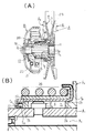
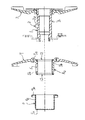
以下、本発明を図面に基づいて説明する。図1は、本発明における従動プーリ機構を示したものである。その従動プーリAは、図1(A),(B)に示すように、固定プーリ半体A1 と可動プーリ半体A2 とから構成される。その固定プーリ半体A1は、図2,図3(A)等に示すように、中空状の固定側プーリ軸1と、扁平円錐状の固定側プーリフェース3とが形成されている。その固定側プーリ軸1の外周側面の所定箇所には、ガイドピン2が装着されている。
Hereinafter, the present invention will be described with reference to the drawings. FIG. 1 shows a driven pulley mechanism according to the present invention. The driven pulley A is composed of a fixed pulley half A 1 and a movable pulley half A 2 as shown in FIGS. As shown in FIGS. 2 and 3A, the fixed pulley half A 1 is formed with a hollow fixed
該ガイドピン2は、円筒状に形成され、前記固定側プーリ軸1の所定箇所に圧入されている。可動プーリ半体A2 は、図2,図3(B)等に示すように、中空状の可動側プーリ軸5,ガイド長孔6と扁平円錐状の可動側プーリフェース7から構成される。その可動側プーリ軸5の軸方向の端部の端面には、その内周面側に沿って周状凹部5aが形成されている。該周状凹部5aは、周方向に直交する断面が略方形状に形成されたものであり、オイルシール12が挿入固着されるようになっている。
The
その固定プーリ半体A1の固定側プーリ軸1は、図1(A)に示すように、遠心クラッチBとの間に設けられた従動軸10に回動自在に支承されている。ニードルベアリング及びボールベアリング等の軸受11を介してこの固定プーリ半体A1の固定側プーリ軸1の外周に前記可動プーリ半体A2 の可動側プーリ軸5が摺動自在に装着されている。そして、固定プーリ半体A1と可動プーリ半体A2 における固定側プーリフェース3と可動側プーリフェース7とが相対向して、無端Vベルト23が掛けられる。
The
その固定プーリ半体A1と可動プーリ半体A2 とからなる従動プーリAは、図示しない駆動側プーリと対をなす。前記ガイド長孔6には、図1に示すように、前記固定側プーリ軸1に装着されたガイドピン2が挿入される。このガイドピン2は、図1(B)に示すように、回転自在なガイドローラ2aが装着されており、前記可動側プーリ軸5はガイド長孔6と、前記ガイドピン2の係合によって案内され、前記固定側プーリ軸1と可動側プーリ軸5とが相互に周方向に回動することなく、軸方向に沿って相互に摺動動作が行なえるようになっている。その可動側プーリ軸5の外周には、外筒9を装着される。
The driven pulley A composed of the fixed pulley half A 1 and the movable pulley half A 2 makes a pair with a driving pulley (not shown). As shown in FIG. 1, a
該外筒9は、円筒部9aと鍔状部9bとから構成されている。その円筒部9aには、前記可動プーリ半体A2 の可動側プーリ軸5が挿入されるものであって、円筒部9aの内径は、可動側プーリ軸5が円滑に入り込むことができる程度である。前記可動側プーリ軸5の外周を円筒部9aにて覆われることにより、前記ガイド長孔6は周囲が略閉鎖状となった空隙部を構成する。この空隙部は、潤滑油貯留室S1 となり、前記ガイド長孔6に充填されたグリース等の潤滑剤が外部に漏れないように溜めておくことができるようになっている。
The outer cylinder 9 is composed of a
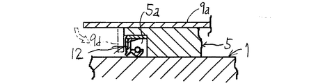
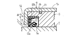
その可動側プーリ軸5の軸方向端部には、図3(B),図4及び図5等に示すように、前述したように周状凹部5aが形成されており、該周状凹部5aにオイルシール12が挿入装着されている。この場合、オイルシール12は周状凹部5aに対して圧入状態で装着されるものであるが、すきま嵌め状態でもかまわない。そのオイルシール12は、そのシール面が前記固定プーリ半体A1の固定側プーリ軸1の外周面に摺接されている。
As shown in FIGS. 3 (B), 4 and 5, etc., the
また、前記可動側プーリ軸5の軸方向中間部には断面凹状の潤滑油貯留室S1が形成され、この潤滑油貯留室S1は固定側プーリ軸1に穿設した連通孔1aを介して、固定側プーリ軸1と前記従動軸10との間に形成された空隙部となる潤滑油貯留室S2 に連通されている。その鍔状部9bは、後述するコイルバネ14からの弾発力を受けるためのかばね座として使用される部位である。その鍔状部9bは、前記可動プーリ半体A2 の可動側プーリフェース7の背面側(Vベルトと接触する面とは反対側となる側)に当接し、前記コイルバネ14の弾性力を伝達するものである。
In addition, a lubricating oil storage chamber S1 having a concave cross section is formed at an axially intermediate portion of the
その外筒9の軸方向端部には、円筒部9aの内径中心部側に向かって折曲されてオイルシールの外側面を覆うようにして折曲部9dが形成されている。該折曲部9dは、前記円筒部9aの端縁側において、その直径方向中心側に向かって略直角状に折曲形成されたものである〔図1(B)参照〕。この折曲部9dは、円板状に形成され、その中心に可動プーリ半体A2 の可動側プーリ軸5が挿通することになる。前記折曲部9dの内周側端縁は、前記可動側プーリ軸5の外周に極めて近接した状態にすることが好まく、しかもその近接状態は、前記固定側プーリ軸1に接触しない程度とする。その折曲部9dは、〔図1(B)参照〕前記オイルシール12の外側の側面を覆う役目をなし、この折曲部9dがオイルシール12のための防壁(堰)となって、図5に示すように、外部からの塵挨の侵入を防ぐことができ、製品として安定した耐久性を保つことができる。
A
また、外筒9の折曲部9dは、円筒部9aの軸方向端部における折り曲げ加工となっているため、それによって外筒9全体の力学的強度を向上させる補強となり、その外筒9自体の強度が高くなる。そのため、折り曲げ加工が施されない従来の外筒は強度が弱く、歪も生じやすいものであったが、本発明における外筒9はその直径方向の折曲部により成形後の変形が防げ、形状を維持することが容易となり、加工工数も削減できる。なお、前記可動側プーリフェース7のボス部7aにもオイルシールが装着されており、このオイルシールは前記ボス部7aに軸方向に凹む収納部が形成され、この収納部にオイルシールが収納装着されている〔図1(A)参照〕。
Further, since the
潤滑油貯留室S2 内の潤滑油(グリス)は、ニードルベアリング,ボールベアリング等の軸受11に給油されるとともに、従動側プーリの回転による遠心力をうけて連通孔1aを通って潤滑油貯留室S1 に圧送され、潤滑油貯留室S1 内に貯留された潤滑油が固定側プーリ軸1,可動側プーリ軸5間のガイドピン2とガイド長孔6との係合箇所に送り込まれ、潤滑させ、可動プーリ半体A2 を常に円滑に移動させることができる。
Lubricating oil (grease) in the lubricating oil storage chamber S 2 is supplied to the bearing 11 such as a needle bearing and a ball bearing, and receives the centrifugal force due to the rotation of the driven pulley and stores the lubricating oil through the communication hole 1a. The lubricating oil stored in the lubricating oil storage chamber S 1 is pumped into the chamber S 1 , and is sent to the engagement portion between the
前記従動プーリAには、図1(A)に示すように、乾式摩擦遠心クラッチBが隣接して配置されている。その従動プーリAの固定側プーリ軸1の左端には、この遠心クラッチBを構成する駆動プレート20が固着されており、無端Vベルト23によって固定プーリ半体A1に伝達された回転力は、前記固定側プーリ軸1を通じて前記駆動プレート20に伝えられる。次いで、遠心ウェイト21およびクラッチアウタ22を経て前記従動軸10に伝達される。
As shown in FIG. 1A, a dry friction centrifugal clutch B is disposed adjacent to the driven pulley A. A
前記可動プーリ半体A2 の可動側プーリフェース7の裏面側と、前記駆動プレート20との間にはコイルバネ14が配置されている。そのコイルバネ14は、外筒9の外周側に配置され、そのコイルバネ14の長手方向一端側が前記駆動プレート20に当接し、また、コイルバネ14の長手方向他端側が外筒9の鍔状部9bに当接して、その鍔状部9bを介して前記可動側プーリフェース7を固定プーリ半体A1の固着側プーリフェース3に接近するように弾性的付勢している〔図1(A),(B)参照〕。
A
無段変速機の遠心クラッチBの前方には、図示しない駆動プーリが設けられており、駆動側プーリも前記従動プーリAと同様に固定プーリ半体と可動プーリ半体とから構成されている。そして、その駆動プーリと従動プーリとの間に無端Vベルト23が掛け渡され、エンジン回転数に応じて駆動側の可動プーリ半体が遠心力により軸線方向に移動することにより、駆動側における固定側プーリフェースと可動側プーリフェースに巻き掛かられている領域の無端Vベルト23の半径が変化し、これに応じて従動プーリAにおける無端Vベルト23の巻きかけられている領域の半径も変化する。こにれよって、エンジン出力軸の回転数が自動的にかつ無段的に変速されて、従動プーリAに伝えられる。
A driving pulley (not shown) is provided in front of the centrifugal clutch B of the continuously variable transmission, and the driving pulley is composed of a fixed pulley half and a movable pulley half in the same manner as the driven pulley A. Then, an endless V-
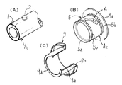
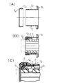
次に、前記外筒9の折曲部9d箇所を別部材とすることもある〔図6(A)参照〕。これは、該折曲部9dに、前記円筒部9aの外周に重合する接続用円筒部9d1 が形成され、該接続用円筒部9d1 を円筒部9aの軸端に重合状態で接合させる構造としたものである。この接続用円筒部9d1 は円筒部9aに溶接等の固着手段を介して接合固着したり、或いは接続用円筒部9d1 を円筒部9aに圧入状態で固着してもかまわない〔図6(B),(C)参照〕。このように、折曲部9dを外筒9か独立した別部材とすることにより、従来タイプの可変プーリ装置において、本発明における外筒9に相当する部材に、折曲部9dを装着することにより、本発明のような構成とすることができる。
Next, the
本発明では、前記オイルシール12ともに、Oリング13が併用されている。前記可動プーリ半体A2 の可動側プーリ軸5にOリング13が装着される溝5bが形成される。そして、前記外筒9の円筒部9aの内周面と固定側プーリ軸1との間が前記Oリング13によりシールされるものである。Oリング13をオイルシール12と併用することにより、オイルシール12と可動側プーリ軸5との間の潤滑油の漏れを防止するとともに、Oリング13により可動側プーリ軸5と外筒9との間の潤滑油の漏れも確実に防止することができる。なお、前記可動側プーリ軸5と外筒9とが十分な密着状態を維持する場合には、Oリング13は必ずしも必要ないものである。
In the present invention, an O-
本発明では、前記外筒9の軸方向端部がオイルシール12の外側端の側面を覆うようにして折曲部9dが形成されているので、その折曲部9dが防壁(堰)となって外部からの塵埃侵入をその端部によって防ぐことができ、製品として安定した耐久性を保つことができる。さらに、外筒9の折曲部9dによって、潤滑油の外部漏出がなくなるため、潤滑油が遠心クラッチに飛散することがない。
In the present invention, since the
よって、遠心クラッチのクラッチウェイトの摩擦係合部に潤滑油が付着することがないため、性能が安定し、製品自体の信頼性,耐久性が良くなる。また、前記折曲部9dによって、外部からの塵挨侵入を防ぐことができ、オイルシール12のリップ部12aに塵挨の付着がなくなるため、リップ自体の劣化が促進しにくくなり、安定したシール性を保つことができる。
Therefore, since the lubricating oil does not adhere to the friction engagement portion of the clutch weight of the centrifugal clutch, the performance is stabilized and the reliability and durability of the product itself are improved. Further, the
さらに前記折曲部9dによって、可動側プーリ軸5から離れたりしてしまうようなことを防止することができ、製品自体の信頼性を高くすることができる。さらに折曲部9dは、外筒9の補強となり、外筒9自体の強度を高くすることができる。また外筒9の折曲部9dは折り曲げ加工にて形成可能なため、製造が簡単で、製造コストを低く抑えることができる。
Further, the
A…従動プーリ、A1 …固定プーリ半体、A2 …可動プーリ半体、
1…固定側プーリ軸、1a…連通孔、2…ガイドピン、3…固定側プーリフェース、
5…可動側プーリ軸、5a…周状凹部、6…ガイド長孔、7…可動側プーリフェース、
9…外筒、9c…段差部、9d…折曲部、9d1 …接続用円筒部、12…オイルシール、12a…リップ部。
A ... driven pulley, A 1 ... fixed pulley half, A 2 ... movable pulley half,
DESCRIPTION OF
5 ... movable pulley shaft, 5a ... circumferential recess, 6 ... guide slot, 7 ... movable pulley face,
9 ... outer cylinder, 9c ... stepped portion, 9d ... folded portion, 9d 1 ... connecting cylindrical part, 12 ... oil seal, 12a ... lip.
Claims (4)
Priority Applications (1)
| Application Number | Priority Date | Filing Date | Title |
|---|---|---|---|
| JP2004108406A JP4511230B2 (en) | 2004-03-31 | 2004-03-31 | Variable pulley device |
Applications Claiming Priority (1)
| Application Number | Priority Date | Filing Date | Title |
|---|---|---|---|
| JP2004108406A JP4511230B2 (en) | 2004-03-31 | 2004-03-31 | Variable pulley device |
Publications (2)
| Publication Number | Publication Date |
|---|---|
| JP2005291402A true JP2005291402A (en) | 2005-10-20 |
| JP4511230B2 JP4511230B2 (en) | 2010-07-28 |
Family
ID=35324554
Family Applications (1)
| Application Number | Title | Priority Date | Filing Date |
|---|---|---|---|
| JP2004108406A Expired - Fee Related JP4511230B2 (en) | 2004-03-31 | 2004-03-31 | Variable pulley device |
Country Status (1)
| Country | Link |
|---|---|
| JP (1) | JP4511230B2 (en) |
Cited By (3)
| Publication number | Priority date | Publication date | Assignee | Title |
|---|---|---|---|---|
| JP2013122274A (en) * | 2011-12-09 | 2013-06-20 | Kanzaki Kokyukoki Manufacturing Co Ltd | Pulley type continuously variable transmission |
| WO2015146616A1 (en) * | 2014-03-24 | 2015-10-01 | ジヤトコ株式会社 | Vehicular stepless transmission equipped with seal mechanism |
| EP4582719A1 (en) * | 2024-01-02 | 2025-07-09 | Polaris Industries Inc. | Driven clutch for continuously variable transmission |
Citations (4)
| Publication number | Priority date | Publication date | Assignee | Title |
|---|---|---|---|---|
| JPS61605Y2 (en) * | 1982-09-16 | 1986-01-10 | ||
| JPS61160658A (en) * | 1984-11-15 | 1986-07-21 | ヴアレオ | Driving wheel for transmission, around wheel center thereof sealing ring is mounted |
| JPH037568U (en) * | 1990-06-19 | 1991-01-24 | ||
| JPH0658393A (en) * | 1992-04-10 | 1994-03-01 | Borg Warner Automot Diversified Transmission Prod Corp | Torque gear |
-
2004
- 2004-03-31 JP JP2004108406A patent/JP4511230B2/en not_active Expired - Fee Related
Patent Citations (4)
| Publication number | Priority date | Publication date | Assignee | Title |
|---|---|---|---|---|
| JPS61605Y2 (en) * | 1982-09-16 | 1986-01-10 | ||
| JPS61160658A (en) * | 1984-11-15 | 1986-07-21 | ヴアレオ | Driving wheel for transmission, around wheel center thereof sealing ring is mounted |
| JPH037568U (en) * | 1990-06-19 | 1991-01-24 | ||
| JPH0658393A (en) * | 1992-04-10 | 1994-03-01 | Borg Warner Automot Diversified Transmission Prod Corp | Torque gear |
Cited By (7)
| Publication number | Priority date | Publication date | Assignee | Title |
|---|---|---|---|---|
| JP2013122274A (en) * | 2011-12-09 | 2013-06-20 | Kanzaki Kokyukoki Manufacturing Co Ltd | Pulley type continuously variable transmission |
| WO2015146616A1 (en) * | 2014-03-24 | 2015-10-01 | ジヤトコ株式会社 | Vehicular stepless transmission equipped with seal mechanism |
| JP2015183754A (en) * | 2014-03-24 | 2015-10-22 | ジヤトコ株式会社 | Continuously variable transmission for vehicles with seal mechanism |
| KR101836024B1 (en) | 2014-03-24 | 2018-03-07 | 쟈트코 가부시키가이샤 | Vehicular stepless transmission equipped with seal mechanism |
| US9970516B2 (en) | 2014-03-24 | 2018-05-15 | Jatco Ltd | Vehicle continuously variable transmission equipped with seal mechanism |
| EP4582719A1 (en) * | 2024-01-02 | 2025-07-09 | Polaris Industries Inc. | Driven clutch for continuously variable transmission |
| US12612956B2 (en) | 2024-01-02 | 2026-04-28 | Polaris Industries Inc. | Driven clutch for continuously variable transmission |
Also Published As
| Publication number | Publication date |
|---|---|
| JP4511230B2 (en) | 2010-07-28 |
Similar Documents
| Publication | Publication Date | Title |
|---|---|---|
| KR102175892B1 (en) | Silk hat type wave gear device | |
| WO2012014069A1 (en) | Roller bearing with seal integral with cage and camshaft apparatus having such a roller bearing | |
| US7909140B2 (en) | Lubricating structure of planetary gear mechanism | |
| JP4511230B2 (en) | Variable pulley device | |
| JPH08178004A (en) | V-belt type automatic transmission | |
| FR2903468A1 (en) | Torsion oscillation damper i.e. fly-wheel, has bearing formed of smooth and ball bearings receiving radial and axial operating forces, respectively, and intermediate space of each of sides of rolling units provided as grease chambers | |
| JP2005291403A (en) | Variable pulley device | |
| JP2005291401A (en) | Variable pulley device | |
| JP3472003B2 (en) | Rotary parts with built-in clutch | |
| JPH10103390A (en) | Built-in with clutch type rotary part | |
| JP4306032B2 (en) | Pulley device with built-in one-way clutch for alternator | |
| US20230009118A1 (en) | Oil passage structure | |
| JP2007218414A (en) | Bearing seal structure for belt type automatic transmission | |
| JPS622349Y2 (en) | ||
| JP2020063785A (en) | Damper device | |
| JPH11148549A5 (en) | ||
| JP2000291785A (en) | Pulley device with built-in one-way clutch for alternator | |
| JP2001208154A (en) | Friction roller type transmission with clutch mechanism | |
| JPS60252858A (en) | V-belt stepless speed change gear | |
| JP4513246B2 (en) | Friction roller transmission and friction roller transmission with motor | |
| JP2005009583A (en) | One-way clutch built-in pulley device | |
| JPH1113848A (en) | Friction roller type transmission | |
| JP2000320578A (en) | Pulley device with built-in one-way clutch for alternator | |
| JP2002372133A (en) | Oil supply mechanism | |
| JPH07317808A (en) | Complex bearing for one-way clutch |
Legal Events
| Date | Code | Title | Description |
|---|---|---|---|
| A621 | Written request for application examination |
Free format text: JAPANESE INTERMEDIATE CODE: A621 Effective date: 20061017 |
|
| A131 | Notification of reasons for refusal |
Free format text: JAPANESE INTERMEDIATE CODE: A131 Effective date: 20091124 |
|
| A521 | Written amendment |
Free format text: JAPANESE INTERMEDIATE CODE: A523 Effective date: 20100125 |
|
| TRDD | Decision of grant or rejection written | ||
| A01 | Written decision to grant a patent or to grant a registration (utility model) |
Free format text: JAPANESE INTERMEDIATE CODE: A01 Effective date: 20100413 |
|
| A01 | Written decision to grant a patent or to grant a registration (utility model) |
Free format text: JAPANESE INTERMEDIATE CODE: A01 |
|
| A61 | First payment of annual fees (during grant procedure) |
Free format text: JAPANESE INTERMEDIATE CODE: A61 Effective date: 20100506 |
|
| FPAY | Renewal fee payment (event date is renewal date of database) |
Free format text: PAYMENT UNTIL: 20130514 Year of fee payment: 3 |
|
| R150 | Certificate of patent or registration of utility model |
Free format text: JAPANESE INTERMEDIATE CODE: R150 |
|
| FPAY | Renewal fee payment (event date is renewal date of database) |
Free format text: PAYMENT UNTIL: 20140514 Year of fee payment: 4 |
|
| R250 | Receipt of annual fees |
Free format text: JAPANESE INTERMEDIATE CODE: R250 |
|
| LAPS | Cancellation because of no payment of annual fees |