JP2005291400A - Method for manufacturing vacuum heat insulating material and method for manufacturing heat insulating container - Google Patents
Method for manufacturing vacuum heat insulating material and method for manufacturing heat insulating container Download PDFInfo
- Publication number
- JP2005291400A JP2005291400A JP2004108344A JP2004108344A JP2005291400A JP 2005291400 A JP2005291400 A JP 2005291400A JP 2004108344 A JP2004108344 A JP 2004108344A JP 2004108344 A JP2004108344 A JP 2004108344A JP 2005291400 A JP2005291400 A JP 2005291400A
- Authority
- JP
- Japan
- Prior art keywords
- plate body
- heat insulating
- vacuum heat
- vacuum
- fitting
- Prior art date
- Legal status (The legal status is an assumption and is not a legal conclusion. Google has not performed a legal analysis and makes no representation as to the accuracy of the status listed.)
- Pending
Links
Images
Landscapes
- Thermal Insulation (AREA)
- Thermally Insulated Containers For Foods (AREA)
Abstract
【課題】 本発明は、従来にない作用効果を発揮する画期的な真空断熱材の製造方法及び断熱容体の製造方法を提供することを目的とする。
【解決手段】 外板体1と内板体2とで構成され、両者の間に真空加熱処理により作出される真空層3が設けられた板状の真空断熱材の製造方法であって、前記内板体2の周縁部には立ち上がり部2aが設けられ、また、この立ち上がり部2aを嵌入する嵌入凹部1aが外板体1の周縁部に設けられ、内板体2と外板体1とを重合して前記嵌入凹部1aに前記立ち上がり部2aを嵌入させ、該立ち上がり部2aと嵌入凹部1aとの嵌合部7にロウ材9を配設して真空加熱処理をし、前記嵌合部7から脱気して外板体1と内板体2との間を真空にするとともに、溶融したロウ材9で前記嵌合部7を閉塞する真空断熱材の製造方法である。
【選択図】 図1
PROBLEM TO BE SOLVED: To provide an epoch-making method for manufacturing a vacuum heat insulating material and a method for manufacturing a heat insulating container that exhibit an unprecedented effect.
A method of manufacturing a plate-shaped vacuum heat insulating material, which is composed of an outer plate body 1 and an inner plate body 2 and is provided with a vacuum layer 3 created by vacuum heating treatment between the two, A rising portion 2 a is provided at the peripheral edge of the inner plate body 2, and a fitting recess 1 a into which the rising portion 2 a is inserted is provided at the peripheral edge portion of the outer plate body 1, and the inner plate body 2 and the outer plate body 1 The rising portion 2a is inserted into the insertion concave portion 1a, and a brazing material 9 is disposed on the fitting portion 7 between the rising portion 2a and the insertion concave portion 1a to perform a vacuum heat treatment, and the fitting portion 7 is a method for producing a vacuum heat insulating material in which the space between the outer plate body 1 and the inner plate body 2 is evacuated to form a vacuum and the fitting portion 7 is closed with a molten brazing material 9.
[Selection] Figure 1
Description
本発明は、真空断熱材の製造方法及び断熱容体の製造方法に関するものである。 The present invention relates to a method for manufacturing a vacuum heat insulating material and a method for manufacturing a heat insulating container.
従来から、水筒やポットなどの断熱容体の周壁構造として、外壁と内壁との間に真空層を形成した真空二重断熱構造が一般的とされているが、この外壁と内壁との間を真空にすることで生じる大気圧の影響を考慮して、これらの真空二重断熱構造の周壁を有する容体は専ら円筒状とされている。 Conventionally, a vacuum double heat insulation structure in which a vacuum layer is formed between the outer wall and the inner wall is generally used as the peripheral wall structure of a heat insulating container such as a water bottle or a pot. A vacuum is formed between the outer wall and the inner wall. In consideration of the influence of atmospheric pressure generated by the above, the container having the peripheral wall of these vacuum double heat insulating structures is exclusively cylindrical.
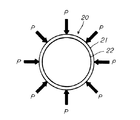
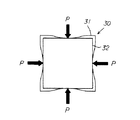
即ち、図8に図示したように円筒状の容体20とした場合には、大気圧(図8中の矢印P)を容体20を構成する周壁全体で支持することができる為、外壁21が凹んで内壁22とくっついてしまうようなことはないが、図9に図示したように角筒状の容体30とした場合には、大気圧(図9中の矢印P)を容体30を構成する各周壁が単独で支持することになる為、この各周壁を構成する外壁31の中央部が内側に凹んで内壁32とくっついてしまい(大気圧を平面で支持する形状だと凹み易い。)、見た目が悪くて商品としての価値がなくなるのは勿論、断熱構造としては致命的となるからである。
That is, when the
ところが、角筒状の容体は、円筒状の容体に比して容積効率(容体自体を他の収納空間へ収納する際の収納効率及び容体内に液体などを収納する際の収納効率)が良いという面があり、よって、真空二重断熱構造の壁部を具備した角筒状の容体を得たいという要望もある。 However, the rectangular tube-shaped container has better volumetric efficiency (storage efficiency when storing the container itself in another storage space and storage efficiency when storing liquid or the like in the container) than the cylindrical container. Therefore, there is also a demand for obtaining a rectangular tube-shaped container having a wall portion of a vacuum double heat insulating structure.
そこで、本出願人は、特願2003−400701の通り、真空二重断熱構造の壁部を具備した角筒状の容体を実現し得る板状の真空断熱材を提案している(以下、従来例と言う。)。 Therefore, the present applicant has proposed a plate-like vacuum heat insulating material capable of realizing a rectangular tube-shaped container having a wall portion of a vacuum double heat insulating structure as described in Japanese Patent Application No. 2003-400701 (hereinafter referred to as “conventional”). Say an example.)
これは、外板体と内板体とで構成され、両者の間に真空加熱処理により作出される真空層が設けられた板状のものであり、外板体と内板体とで形成される内空間に耐熱性介在物を配設せしめられたものである。 This is composed of an outer plate body and an inner plate body, and is a plate-like thing provided with a vacuum layer created by vacuum heat treatment between them, and is formed by an outer plate body and an inner plate body. Heat-resistant inclusions are disposed in the inner space.
従って、従来例は、外板体と内板体との内空間に耐熱性介在物が配設されているため、内空間を真空加熱処理により真空にしても外板体と内板体とが大気圧によって内側へ凹むことが阻止されており、よって、大気圧によって変形しない板状の真空断熱材が得られることになり、この板状の真空断熱材を複数枚接合することで角筒状の容体を製造することができる。 Therefore, in the conventional example, since the heat-resistant inclusions are arranged in the inner space between the outer plate body and the inner plate body, the outer plate body and the inner plate body are not formed even if the inner space is evacuated by vacuum heat treatment. Indentation by the atmospheric pressure is prevented, so a plate-like vacuum heat insulating material that is not deformed by atmospheric pressure is obtained, and a rectangular tube shape is formed by joining a plurality of plate-like vacuum heat insulating materials. Can be produced.
本出願人は、この板状の真空断熱材について更なる実験・研究を重ね、その結果、製造効率が良好な真空断熱材の製造方法及び断熱容体の製造方法を開発した。 The present applicant repeated further experiments and research on this plate-like vacuum heat insulating material, and as a result, developed a method for manufacturing a vacuum heat insulating material and a method for manufacturing a heat insulating container with good manufacturing efficiency.
添付図面を参照して本発明の要旨を説明する。 The gist of the present invention will be described with reference to the accompanying drawings.
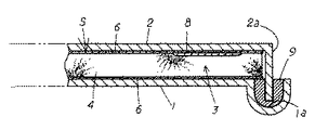
外板体1と内板体2とで構成され、両者の間に真空加熱処理により作出される真空層3が設けられた板状の真空断熱材の製造方法であって、前記内板体2の周縁部には立ち上がり部2aが設けられ、また、この立ち上がり部2aを嵌入する嵌入凹部1aが外板体1の周縁部に設けられ、内板体2と外板体1とを重合して前記嵌入凹部1aに前記立ち上がり部2aを嵌入させ、該立ち上がり部2aと嵌入凹部1aとの嵌合部7にロウ材9を配設して真空加熱処理をし、前記嵌合部7から脱気して外板体1と内板体2との間を真空にするとともに、溶融したロウ材9で前記嵌合部7を閉塞することを特徴とする真空断熱材の製造方法に係るものである。
A method of manufacturing a plate-like vacuum heat insulating material, which is composed of an outer plate body 1 and an inner plate body 2 and is provided with a vacuum layer 3 created by vacuum heat treatment between the two, wherein the inner plate body 2 Is provided with a rising
また、外板体1と内板体2とで構成され、両者の間に真空加熱処理により作出される真空層3が設けられた板状の真空断熱材の製造方法であって、前記外板体1の周縁部には立ち上がり部が設けられ、また、この立ち上がり部を嵌入する嵌入凹部が内板体2の周縁部に設けられ、外板体1と内板体2とを重合して前記嵌入凹部に前記立ち上がり部を嵌入させ、該立ち上がり部と嵌入凹部との嵌合部7にロウ材9を配設して真空加熱処理をし、前記嵌合部7から脱気して外板体1と内板体2との間を真空にするとともに、溶融したロウ材9で前記嵌合部7を閉塞することを特徴とする真空断熱材の製造方法に係るものである。
A method of manufacturing a plate-like vacuum heat insulating material, which is composed of an outer plate body 1 and an inner plate body 2 and is provided with a vacuum layer 3 created by vacuum heat treatment between the two, A rising portion is provided at the peripheral portion of the body 1, and an insertion recess for inserting the rising portion is provided at the peripheral portion of the inner plate body 2, and the outer plate body 1 and the inner plate body 2 are overlapped to overlap the body plate 2. The rising portion is inserted into the insertion concave portion, the brazing material 9 is disposed in the
また、請求項1,2いずれか1項に記載の真空断熱材の製造方法において、前記外板体1と内板体2とで形成される内空間Sに前記真空加熱処理の加熱に耐え得る耐熱性介在物4が配設せしめられていることを特徴とする真空断熱材の製造方法に係るものである。 Moreover, in the manufacturing method of the vacuum heat insulating material according to any one of claims 1 and 2, the inner space S formed by the outer plate body 1 and the inner plate body 2 can withstand the heating of the vacuum heat treatment. The present invention relates to a method for manufacturing a vacuum heat insulating material, in which a heat-resistant inclusion 4 is disposed.
また、請求項3記載の真空断熱材の製造方法において、前記耐熱性介在物4としてセラミックから成る耐熱性介在物4を採用したことを特徴とする真空断熱材の製造方法に係るものである。 The method for manufacturing a vacuum heat insulating material according to claim 3, wherein the heat resistant inclusion 4 made of ceramic is employed as the heat resistant inclusion 4.
また、請求項1〜4いずれか1項に記載の真空断熱材の製造方法において、外板体1の内面または内板体2の内面のいずれか一方、若しくは双方に、銅,アルミ,銀,ニッケルなどの熱輻射材から成る熱輻射層6が形成されていることを特徴とする真空断熱材の製造方法に係るものである。 Moreover, in the manufacturing method of the vacuum heat insulating material of any one of Claims 1-4, in any one or both of the inner surface of the outer plate body 1, the inner plate body 2, or both, copper, aluminum, silver, The present invention relates to a method for manufacturing a vacuum heat insulating material, in which a heat radiation layer 6 made of a heat radiation material such as nickel is formed.
また、外板体1と内板体2とで構成され、両者の間に真空加熱処理により作出される真空層3が設けられた板状の真空断熱材5を複数接合して形成される断熱容体の製造方法であって、前記内板体2の周縁部には立ち上がり部2aが設けられ、また、この立ち上がり部2aを嵌入する嵌入凹部1aが外板体1の周縁部に設けられ、内板体2と外板体1とを重合して前記嵌入凹部1aに前記立ち上がり部2aを嵌入させ、該立ち上がり部2aと嵌入凹部1aとの嵌合部7にロウ材9を配設して真空加熱処理をし、前記嵌合部7から脱気して外板体1と内板体2との間を真空にするとともに、溶融したロウ材9で前記嵌合部7を閉塞して板状の真空断熱材5を形成し、この真空断熱材5を適宜接合することで断熱容体を製造することを特徴とする断熱容体の製造方法に係るものである。
Further, a heat insulation formed by joining a plurality of plate-like vacuum heat insulating materials 5 each composed of an outer plate body 1 and an inner plate body 2 and provided with a vacuum layer 3 created by vacuum heat treatment therebetween. In the manufacturing method of the container, a rising
また、外板体1と内板体2とで構成され、両者の間に真空加熱処理により作出される真空層3が設けられた板状の真空断熱材5を複数接合して形成される断熱容体の製造方法であって、前記外板体1の周縁部には立ち上がり部が設けられ、また、この立ち上がり部を嵌入する嵌入凹部が内板体2の周縁部に設けられ、外板体1と内板体2とを重合して前記嵌入凹部に前記立ち上がり部を嵌入させ、該立ち上がり部と嵌入凹部との嵌合部7にロウ材9を配設して真空加熱処理をし、前記嵌合部7から脱気して外板体1と内板体2との間を真空にするとともに、溶融したロウ材9で前記嵌合部7を閉塞して板状の真空断熱材5を形成し、この真空断熱材5を適宜接合することで断熱容体を製造することを特徴とする断熱容体の製造方法に係るものである。
Further, a heat insulation formed by joining a plurality of plate-like vacuum heat insulating materials 5 each composed of an outer plate body 1 and an inner plate body 2 and provided with a vacuum layer 3 created by vacuum heat treatment therebetween. In the manufacturing method of the container, a rising portion is provided in the peripheral portion of the outer plate body 1, and a fitting recess for fitting the rising portion is provided in the peripheral portion of the inner plate body 2. And the inner plate body 2 are superposed so that the rising portion is inserted into the insertion recess, a brazing material 9 is disposed in the
また、請求項6,7いずれか1項に記載の断熱容体の製造方法において、前記外板体1と内板体2とで形成される内空間Sに前記真空加熱処理の加熱に耐え得る耐熱性介在物4が配設せしめられていることを特徴とする断熱容体の製造方法に係るものである。
Moreover, in the manufacturing method of the heat insulation container of any one of
また、外体11と内体12とで構成され、両者の間に真空加熱処理により作出される真空層3が設けられた真空断熱構造を有する断熱容体の製造方法であって、前記外体11の周縁部は嵌入部11aに設定され、また、前記内体12の周縁部には前記嵌入部11aが嵌入される嵌入凹部12aが設けられ、内体12と外体11とを重合して前記嵌入凹部12aに前記嵌入部11aを嵌入させ、該嵌入部11aと嵌入凹部12aとの嵌合部7にロウ材9を配設して真空加熱処理をし、前記嵌合部7から脱気して外体11と内体12との間を真空にするとともに、溶融したロウ材9で前記嵌合部7を閉塞することを特徴とする断熱容体の製造方法に係るものである。
A method for manufacturing a heat insulating container having a vacuum heat insulating structure, which includes an outer body 11 and an
また、外体11と内体12とで構成され、両者の間に真空加熱処理により作出される真空層3が設けられた真空断熱構造を有する断熱容体の製造方法であって、前記内体12の周縁部は嵌入部に設定され、また、前記外体11の周縁部には前記嵌入部が嵌入される嵌入凹部が設けられ、外体11と内体12とを重合して前記嵌入凹部に前記嵌入部を嵌入させ、該嵌入部と嵌入凹部との嵌合部7にロウ材9を配設して真空加熱処理をし、前記嵌合部7から脱気して外体11と内体12との間を真空にするとともに、溶融したロウ材9で前記嵌合部7を閉塞することを特徴とする断熱容体の製造方法に係るものである。
Further, it is a method of manufacturing a heat insulating container having a vacuum heat insulating structure which is composed of an outer body 11 and an
また、請求項9,10いずれか1項に記載の断熱容体の製造方法において、前記外体11と内体12とで形成される内空間Sに前記真空加熱処理の加熱に耐え得る耐熱性介在物4が配設せしめられていることを特徴とする断熱容体の製造方法に係るものである。
Furthermore, in the method for manufacturing a heat insulating container according to any one of
本発明は上述のように構成したから、真空加熱処理により得られた高断熱性を具備した板状の真空断熱材が簡易且つ確実に得られることになるなど従来にない作用効果を発揮する画期的な真空断熱材の製造方法となる。 Since the present invention is configured as described above, a plate-like vacuum heat insulating material having high heat insulating properties obtained by vacuum heat treatment can be obtained easily and reliably. It becomes a manufacturing method of a periodical vacuum heat insulating material.
好適と考える本発明の最良の形態を、図面に基づいて本発明の作用効果を示して簡単に説明する。 BEST MODE FOR CARRYING OUT THE INVENTION The best mode of the present invention considered to be suitable will be briefly described with reference to the drawings, showing the effects of the present invention.
本発明は、例えば内板体2と外板体1とを重合して嵌入凹部1aに立ち上がり部2aを嵌入させ、該立ち上がり部2aと嵌入凹部1aとの嵌合部7にロウ材9を配設して真空加熱処理をし、嵌合部7から脱気して外板体1と内板体2との間を真空にするとともに、溶融したロウ材9で前記嵌合部7を閉塞することになる。
In the present invention, for example, the inner plate body 2 and the outer plate body 1 are superposed so that the rising
従って、溶融することで流動性を生じるため取扱いが厄介とされるロウ材9を確実に嵌入凹部1aに維持することができることになるから、立ち上がり部2aと嵌入凹部1aとの間に形成され、外板体1と内板体2との間の空気を抜くための部位として機能する嵌合部7を簡易且つ確実に閉塞することができることになり、よって、板状の真空断熱材の製造がコスト安にして量産性に秀れることになり、しかも、ロウ材が流れたりせず綺麗に仕上げることができるから板状の真空断熱材の商品価値をより一層向上することができることになる。
Therefore, since the brazing material 9 that is difficult to handle because it generates fluidity by melting can be reliably maintained in the insertion recess 1a, it is formed between the rising
本発明の具体的な実施例1について図面に基づいて説明する。 A first embodiment of the present invention will be described with reference to the drawings.
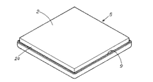
本実施例は、内部に真空層3を有する板状の真空断熱材5の製造方法である。 This embodiment is a method for manufacturing a plate-like vacuum heat insulating material 5 having a vacuum layer 3 inside.
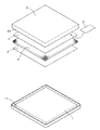
具体的には、この板状の真空断熱材5は、外板体1と内板体2とで構成され、この外板体1と内板体2との間には耐熱性介在物4が配設され、更に、この外板体1と耐熱性介在物4との間及び内板体2と耐熱性介在物4との間には熱輻射層6が形成されている。 Specifically, the plate-like vacuum heat insulating material 5 is composed of an outer plate body 1 and an inner plate body 2, and a heat-resistant inclusion 4 is interposed between the outer plate body 1 and the inner plate body 2. Further, a heat radiation layer 6 is formed between the outer plate 1 and the heat-resistant inclusions 4 and between the inner plate 2 and the heat-resistant inclusions 4.
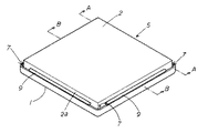
外板体1と内板体2は、夫々図1に図示したように適宜な金属製(ステンレス製)の部材を方形板状に形成したものであり、外板体1が内板体2に比して若干面積が大きくなるように形成されている。 As shown in FIG. 1, the outer plate body 1 and the inner plate body 2 are formed by forming appropriate metal (stainless steel) members into a rectangular plate shape, and the outer plate body 1 becomes the inner plate body 2. The area is slightly larger than that.
内板体2は、その内面の周縁部に突片状の立ち上がり部2aが形成されたものである。
The inner plate body 2 has a protruding piece-like rising
また、外板体2は、その外面の周縁部に外方に向けて突出し、湾曲して折り返された折り返し部1aが設けられたもので、この湾曲折り返し部1aにより形成される凹部は前記立ち上がり部2aが嵌入される嵌入凹部1aとなる。
Further, the outer plate body 2 is provided with a folded portion 1a that protrudes outward at the peripheral edge portion of the outer surface and is bent and folded, and the concave portion formed by the curved folded portion 1a is raised. It becomes the insertion recessed part 1a in which the
よって、外板体1と内板体2との間には内板体2の立ち上がり部2aで周囲が囲まれた内空間Sが形成されるように構成されている。
Therefore, an inner space S is formed between the outer plate body 1 and the inner plate body 2 and is surrounded by the rising
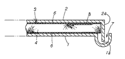
この内板体2の立ち上がり壁2aと外板体1の嵌入凹部1aとの間には、外板体1と内板体2とで形成される内空間Sに後述する耐熱性介在物4を配設せしめた際、嵌合部7が形成されるように設けられており、この嵌合部7は、真空加熱処理を行う際の空気抜き部として機能する。
Between the rising
また、この外板体1に設けた嵌入凹部1aは、真空加熱処理を行った際、嵌入凹部1aと立ち上がり部2aとの間に配設されて溶融したロウ材9が流れ込むロウ材受け部として機能する。
In addition, the insertion recess 1a provided in the outer plate body 1 is disposed between the insertion recess 1a and the rising
尚、外板体1の周縁部に立ち上がり部を設け、内板体2の周縁部に前記立ち上がり部が嵌入される嵌入凹部を湾曲形成して設けるようにしても良い。 It should be noted that a rising portion may be provided at the peripheral edge of the outer plate body 1 and a fitting recess into which the rising portion is inserted at the peripheral edge of the inner plate body 2 may be provided by being curved.
耐熱性介在物4は、図1に図示したようにセラミックを方形板状に形成したものである。 As shown in FIG. 1, the heat-resistant inclusion 4 is a ceramic plate formed in a square plate shape.
本実施例では、セラミックとしてイソライト工業(株)製の「イソウール(商標)1260ブランケット」を採用しており、これは1260℃までの耐熱性を有し、本実施例で使用する真空加熱炉での高温化(約1100℃までの高温状態にできる。)に耐え得るものであり、更に、真空加熱炉を構成する壁面の断熱構造にも使用されるなどそれ自体が秀れた断熱性を有している。その他にも、前記セラミック(繊維)は、軽量で柔軟であり、取り扱い性が非常に秀れている。 In this example, “Iso wool (trademark) 1260 blanket” manufactured by Isolite Industry Co., Ltd. is used as the ceramic, which has heat resistance up to 1260 ° C., and is a vacuum heating furnace used in this example. It can withstand high temperatures (high temperatures up to about 1100 ° C), and it has excellent heat insulation properties such as being used for the heat insulation structure of the wall that constitutes the vacuum heating furnace. doing. In addition, the ceramic (fiber) is lightweight and flexible, and has excellent handling properties.
また、耐熱性介在物4の厚さは、該耐熱性介在物4を外板体1と内板体2との間の空間Sに配設した際、外板体1,内板体2夫々の内面に当接若しくは近接した状態となる厚さに設定される。 Further, the thickness of the heat-resistant inclusion 4 is such that when the heat-resistant inclusion 4 is disposed in the space S between the outer plate body 1 and the inner plate body 2, the outer plate body 1 and the inner plate body 2 respectively. The thickness is set so as to be in contact with or close to the inner surface.
熱輻射層6は、図1に図示したように熱輻射材としての銅を方形シート状(箔状)に形成し、この銅箔6を、外板体1と耐熱性介在物4との間及び内板体2と耐熱性介在物4との間に配設するようにして構成されている。尚、熱輻射層6を形成する熱輻射材としては銅に限らず、例えば金、アルミ、銀、ニッケルでも良く、そして、これらの外板体1の内面と内板体2の内面に熱輻射材をメッキ処理することによって熱輻射層6を形成するようにしても良い。 As shown in FIG. 1, the heat radiation layer 6 is formed by forming copper as a heat radiation material into a rectangular sheet (foil shape), and this copper foil 6 is formed between the outer plate 1 and the heat-resistant inclusion 4. And it is comprised so that it may arrange | position between the inner-plate body 2 and the heat-resistant inclusions 4. FIG. The heat radiating material for forming the heat radiating layer 6 is not limited to copper, but may be gold, aluminum, silver, nickel, for example, and heat radiation is applied to the inner surface of the outer plate 1 and the inner surface of the inner plate 2. The heat radiation layer 6 may be formed by plating the material.
以上の構成から成る板状の真空断熱材5の製造方法について説明する。 The manufacturing method of the plate-shaped vacuum heat insulating material 5 which consists of the above structure is demonstrated.
まず、図1に図示したように外板体1と内板体2夫々の内面に銅箔6を配した状態で、この外板体1と内板体2との空間Sに耐熱性介在物4を挟み込み状態で配設する。この際、真空加熱処理時に外板体1及び内板体2夫々から発生するガスを吸収するガス吸収剤8(ゲッター材)も配設しており、このガス吸収剤8としては約500℃以上の高温化になるとその機能を発揮するガス吸収剤8を採用している。 First, as shown in FIG. 1, in the state where the copper foil 6 is arranged on the inner surfaces of the outer plate body 1 and the inner plate body 2, the heat-resistant inclusions are formed in the space S between the outer plate body 1 and the inner plate body 2. 4 is disposed in a sandwiched state. At this time, a gas absorbent 8 (getter material) that absorbs gas generated from each of the outer plate body 1 and the inner plate body 2 during the vacuum heat treatment is also disposed, and the gas absorbent 8 is about 500 ° C. or higher. The gas absorbent 8 that exhibits its function at a high temperature is employed.
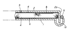
続いて、図2に図示したように嵌合部7の一部が閉塞状態となるようにロウ材9を配設する(図3は図2のA−A断面図、図4は図2のB−B断面図である。)。本実施例では約1000℃で溶融するロウ材9を採用している。従って、このロウ材9の両端部位における嵌合部7が脱気孔として機能する。
Subsequently, as shown in FIG. 2, the brazing material 9 is disposed so that a part of the
続いて、真空加熱炉によって真空加熱処理を行う。 Subsequently, vacuum heat treatment is performed in a vacuum heating furnace.
具体的には、真空加熱炉内の温度を上昇させて約500℃に達した時点においてガス吸収剤8が作用して外板体1及び内板体2から発生するガスを吸収し、更に、空気を抜きながら温度を上昇させ、約1000℃に達した時点でロウ材9は溶融し、この溶融したロウ材9は嵌合部7に流れ込み該嵌合部7の全部を塞ぐことになる(図5,6参照)。
Specifically, when the temperature in the vacuum heating furnace is increased to reach about 500 ° C., the gas absorbent 8 acts to absorb the gas generated from the outer plate 1 and the inner plate 2, The temperature is raised while venting air, and when the temperature reaches about 1000 ° C., the brazing material 9 is melted, and the molten brazing material 9 flows into the
その後、温度を低下させてロウ材9を固化させることで嵌合部7が密閉され真空の空間Sを有する真空断熱材5となる。
Thereafter, the temperature is lowered to solidify the brazing material 9, whereby the
前述した真空加熱炉を使用して真空度合いの高い真空加熱処理を行った際、大気圧の影響から外板体1と内板体2とが変形しようとするが、外板体1と内板体2とで形成される空間Sには真空加熱処理の加熱に耐え得る耐熱性介在物4が介在する為、外板体1と内板体2の変形が防止され、当然外板体1と内板体2とが当接してしまうのも確実に防止されることになる。 When vacuum heat treatment with a high degree of vacuum is performed using the vacuum heating furnace described above, the outer plate body 1 and the inner plate body 2 tend to deform due to the influence of atmospheric pressure. Since the heat-resistant inclusion 4 that can withstand the heat of the vacuum heat treatment is interposed in the space S formed by the body 2, the deformation of the outer plate body 1 and the inner plate body 2 is prevented. It is also reliably prevented that the inner plate body 2 comes into contact.
以上のようにして得られた板状の真空断熱材5は、複数組み合せ(例えば溶接)することで、水筒やポット、その他にもオーブンレンジや冷蔵庫など、壁部に断熱構造が要求される真空二重断熱容体を作出することができ、この真空断熱材5の空間Sが真空になる為、秀れた断熱効果が得られるのは勿論、耐熱性介在物4自体が耐熱性を有するセラミックであるから、特に高温化での使用に適したものとなる。 The plate-like vacuum heat insulating material 5 obtained as described above is a vacuum that requires a heat insulating structure on the wall, such as a water bottle, a pot, and a microwave oven, a refrigerator, etc. by combining (for example, welding). A double heat insulating container can be created, and since the space S of the vacuum heat insulating material 5 becomes a vacuum, an excellent heat insulating effect can be obtained, and the heat resistant inclusion 4 itself is made of a heat resistant ceramic. Therefore, it is particularly suitable for use at high temperatures.
本実施例は上述のように構成したから、溶融することで流動性を生じるため取扱いが厄介とされるロウ材9を確実に嵌入凹部1aに維持することができることになるから、立ち上がり部2aと嵌入凹部1aとの間に形成され、外板体1と内板体2との間の空気を抜くための部位として機能する嵌合部7を簡易且つ確実に閉塞することができることになり、よって、板状の真空断熱材の製造がコスト安にして量産性に秀れることになり、しかも、ロウ材が流れたりせず綺麗に仕上げることができるから板状の真空断熱材の商品価値をより一層向上することができることになる。
Since the present embodiment is configured as described above, the brazing material 9 that is difficult to handle because it is fluid when melted can be reliably maintained in the fitting recess 1a. The
また、本実施例は、真空度合いが非常に高い状態であるから、極めて秀れた高断熱性を具備する真空断熱材5となり、高断熱性が要求される他の製品へ広く適用できることになるなど、板状の真空断熱材5の商品価値を飛躍的に向上することができる。 Moreover, since this embodiment is in a state where the degree of vacuum is very high, the vacuum heat insulating material 5 having extremely excellent high heat insulating properties can be obtained, and can be widely applied to other products requiring high heat insulating properties. Thus, the commercial value of the plate-like vacuum heat insulating material 5 can be dramatically improved.
この他の製品への適用例として、例えばオーブンレンジを構成する壁部に本発明で得られる真空断熱材5を適用することが好適と考えられる。 As an application example to other products, it is considered preferable to apply the vacuum heat insulating material 5 obtained by the present invention to, for example, a wall portion constituting the microwave oven.
具体的には、従来から、オーブンレンジの壁部の厚みは、該壁部内に配設される断熱材の厚さで決定される為、小型軽量化等が極めて困難とされているが、本製造方法で得られる真空断熱材5は薄くても秀れた高断熱性を具備することになる為、このオーブンレンジの壁部を飛躍的に薄くして小型軽量化を達成することができるなど、他の製品に適用した場合において、断熱効果の他にも秀れた作用効果を発揮することになる。 Specifically, conventionally, since the thickness of the wall portion of the microwave oven is determined by the thickness of the heat insulating material disposed in the wall portion, it is extremely difficult to reduce the size and weight. Since the vacuum heat insulating material 5 obtained by the manufacturing method has excellent high heat insulating properties even if it is thin, the wall portion of the microwave oven can be drastically thinned to achieve a reduction in size and weight. In addition, when applied to other products, it exhibits excellent operational effects in addition to the heat insulating effect.
また、本実施例は、外板体1と内板体2とで形成される空間Sを約500℃以上の高温化で真空加熱処理して真空にするものであり、この約500℃以上の高温化とは、高断熱性を達成し得る良好な真空度が得られる温度であって、約500℃以上とすることでガス吸収剤8やロウ材9が作用する温度である。 In this embodiment, the space S formed by the outer plate body 1 and the inner plate body 2 is vacuum-heated at a high temperature of about 500 ° C. or higher to be evacuated. The high temperature is a temperature at which a good degree of vacuum that can achieve high heat insulation is obtained, and is a temperature at which the gas absorbent 8 and the brazing material 9 act when the temperature is about 500 ° C. or higher.
また、本実施例は、耐熱性介在物4としてセラミックから成る耐熱性介在物4を採用したから、真空加熱処理が行えることになり秀れた高断熱性を具備した板状の真空断熱材5が確実に得られることになる。 Moreover, since the heat-resistant inclusion 4 which consists of ceramics was employ | adopted as the heat-resistant inclusion 4 in a present Example, the vacuum heat processing can be performed and the plate-shaped vacuum heat insulating material 5 which has the outstanding high heat insulation property can be performed. Is certainly obtained.
また、本実施例は、前記耐熱性介在物4を板状としたから、真空処理を行うことで変形しようとする外板体1と内板体2とを確実に支持することができ、しかも、真空断熱材5全体にわたって秀れた高断熱性が発揮されることになる。 Further, in this embodiment, since the heat-resistant inclusions 4 are formed in a plate shape, the outer plate body 1 and the inner plate body 2 to be deformed can be surely supported by vacuum treatment, and In addition, excellent high heat insulating properties are exhibited over the entire vacuum heat insulating material 5.
また、本実施例は、外板体1の内面及び内板体2の内面双方に熱輻射材から成る熱輻射層6を形成したから、より一層良好な高断熱性を具備せしめることができる。 Further, in this embodiment, since the heat radiation layer 6 made of the heat radiation material is formed on both the inner surface of the outer plate body 1 and the inner surface of the inner plate body 2, it is possible to provide even better heat insulation.
本発明の具体的な実施例2について図面に基づいて説明する。 A second embodiment of the present invention will be described with reference to the drawings.
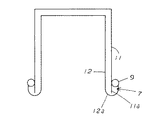
本実施例は、図7に図示したように有底角筒状の外体11と有底角筒状の内体12とで構成され、両者の間に真空加熱処理により作出される真空層3が設けられた真空断熱構造を有する断熱容体の製造方法であって、前記外体11の周縁部(上部開口周縁部)は嵌入部11aに設定され、また、前記内体12の周縁部(上部開口周縁部)には前記嵌入部11aが嵌入される嵌入凹部12aが湾曲形成して設けられ、内体12と外体11とを重合して前記嵌入凹部12aに前記嵌入部11aを嵌入させ、該嵌入部11aと嵌入凹部12aとの嵌合部7にロウ材9を配設して真空加熱処理をし、前記嵌合部7から脱気して外体11と内体12との間を真空にするとともに、溶融したロウ材9で前記嵌合部7を閉塞する断熱容体の製造方法である。
As shown in FIG. 7, this embodiment is composed of a bottomed rectangular tube-shaped outer body 11 and a bottomed rectangular tube-shaped
尚、内体12の周縁部(上部開口周縁部)を嵌入部に設定し、外体11の周縁部(上部開口周縁部)に前記嵌入部が嵌入される嵌入凹部を湾曲形成して設けるようにしても良い。
The peripheral portion (upper opening peripheral portion) of the
従って、本実施例の技術は、有底角筒状の外体11内に所定間隔を介した状態で有底角筒状の内体12を配し、この空間Sに耐熱性介在物4を配設した状態で真空加熱処理を行うことで作出した、有底角筒状の真空二重断熱容体を簡易且つ良好に得ることができる。
Therefore, according to the technique of the present embodiment, the bottomed rectangular tube-shaped
また、仮に円筒状の真空二重断熱容体であっても大気圧の影響を受ける場合はあり、例えば大きな鍋(断熱調理鍋)やドラムカンなどの径の大きな容体の底部分は大気圧の影響を受け易く、従来においては、この底部分を構成する板材にはリブを形成するなどの対策を施していたが製造効率が悪く、そこで、この円筒状の容体の空間Sに耐熱性介在物4を配設した状態で真空加熱処理を行うことで良好な真空断熱構造を具備した円筒状の真空二重断熱容体も簡易且つ良好に得ることができる。 Also, even if it is a cylindrical vacuum double insulated container, it may be affected by atmospheric pressure. For example, the bottom of large containers such as large pots (insulated cooking pots) and drum cans are affected by atmospheric pressure. Conventionally, measures have been taken such as forming ribs on the plate material constituting the bottom portion, but the manufacturing efficiency is poor. Therefore, the heat-resistant inclusion 4 is placed in the space S of the cylindrical container. By performing the vacuum heat treatment in the arranged state, a cylindrical vacuum double heat insulating container having a good vacuum heat insulating structure can be obtained easily and satisfactorily.
その余は実施例1と同様である。 The rest is the same as in Example 1.
尚、本発明は、実施例1,2に限られるものではなく、各構成要件の具体的構成は適宜設計し得るものである。 The present invention is not limited to the first and second embodiments, and the specific configuration of each component can be designed as appropriate.
S 内空間
1 外板体
1a 嵌入凹部
2 内板体
2a 立ち上がり部
3 真空層
7 嵌合部
9 ロウ材
11 外体
11a 嵌入部
12 内体
12a 嵌入凹部
DESCRIPTION OF SYMBOLS S Inner space 1 Outer plate body 1a Insertion recessed part 2
11 outer body
11a insertion part
12 inner body
12a Insertion recess
Claims (11)
11. The method for manufacturing a heat insulating container according to claim 9, wherein a heat-resistant inclusion capable of withstanding the heat of the vacuum heat treatment is disposed in an inner space formed by the outer body and the inner body. A method for producing a heat insulating container.
Priority Applications (1)
| Application Number | Priority Date | Filing Date | Title |
|---|---|---|---|
| JP2004108344A JP2005291400A (en) | 2004-03-31 | 2004-03-31 | Method for manufacturing vacuum heat insulating material and method for manufacturing heat insulating container |
Applications Claiming Priority (1)
| Application Number | Priority Date | Filing Date | Title |
|---|---|---|---|
| JP2004108344A JP2005291400A (en) | 2004-03-31 | 2004-03-31 | Method for manufacturing vacuum heat insulating material and method for manufacturing heat insulating container |
Publications (1)
| Publication Number | Publication Date |
|---|---|
| JP2005291400A true JP2005291400A (en) | 2005-10-20 |
Family
ID=35324552
Family Applications (1)
| Application Number | Title | Priority Date | Filing Date |
|---|---|---|---|
| JP2004108344A Pending JP2005291400A (en) | 2004-03-31 | 2004-03-31 | Method for manufacturing vacuum heat insulating material and method for manufacturing heat insulating container |
Country Status (1)
| Country | Link |
|---|---|
| JP (1) | JP2005291400A (en) |
Cited By (2)
| Publication number | Priority date | Publication date | Assignee | Title |
|---|---|---|---|---|
| JP2010260557A (en) * | 2009-04-30 | 2010-11-18 | Panasonic Corp | Method for producing gas adsorption device and gas adsorption device |
| JP2023112127A (en) * | 2019-04-11 | 2023-08-10 | サーモス株式会社 | Insulated containers and containers with lids |
-
2004
- 2004-03-31 JP JP2004108344A patent/JP2005291400A/en active Pending
Cited By (3)
| Publication number | Priority date | Publication date | Assignee | Title |
|---|---|---|---|---|
| JP2010260557A (en) * | 2009-04-30 | 2010-11-18 | Panasonic Corp | Method for producing gas adsorption device and gas adsorption device |
| JP2023112127A (en) * | 2019-04-11 | 2023-08-10 | サーモス株式会社 | Insulated containers and containers with lids |
| JP7539530B2 (en) | 2019-04-11 | 2024-08-23 | サーモス株式会社 | Insulated containers and containers with lids |
Similar Documents
| Publication | Publication Date | Title |
|---|---|---|
| CN108290674B (en) | Vacuum insulated container and method of forming same | |
| JP5188797B2 (en) | Insulated cooking container | |
| CN203168831U (en) | Cooking appliance | |
| JP2008249003A (en) | Vacuum insulation panel and equipment provided with the same | |
| JP2005163848A (en) | Method for manufacturing vacuum heat insulating material and method for manufacturing heat insulating container | |
| JPH11221667A (en) | Manufacturing method of metal vacuum double container | |
| JPH07313383A (en) | Insulation jar and its manufacturing method | |
| JP4365736B2 (en) | Method for manufacturing vacuum insulator | |
| JPH11164784A (en) | Metal vacuum double container | |
| JP2005291400A (en) | Method for manufacturing vacuum heat insulating material and method for manufacturing heat insulating container | |
| CN107380741B (en) | A kind of manufacturing method of the strong cool-bag of air-tightness and its cool-bag of manufacture | |
| JP4279655B2 (en) | Method for manufacturing vacuum heat insulating material and method for manufacturing heat insulating container | |
| JPS59103634A (en) | Vacuum heat insulating container | |
| CN107380740B (en) | A kind of high-efficiency insulation container manufacturing method and the insulation container manufactured thereof | |
| US20240025621A1 (en) | Container and method of forming a container | |
| JP4746898B2 (en) | Insulated container and manufacturing method thereof | |
| JP2006275186A (en) | Insulated container and manufacturing method thereof | |
| JPH0274223A (en) | Manufacturing method of metal double container for cold/thermal insulation | |
| JPH0415687B2 (en) | ||
| JP3699453B2 (en) | Method for manufacturing insulated container with handle and insulated container with handle | |
| CN1140047A (en) | Thermal insulation cooking pot | |
| JPS63206213A (en) | Production of metal double container | |
| TWM531343U (en) | Circumferential-groove sink-cover sealing temperature-keeping container | |
| AU2007242971B2 (en) | Insulated Cooking Vessel | |
| JP2018146067A (en) | Vacuum insulation structure |
Legal Events
| Date | Code | Title | Description |
|---|---|---|---|
| A977 | Report on retrieval |
Free format text: JAPANESE INTERMEDIATE CODE: A971007 Effective date: 20080328 |
|
| A131 | Notification of reasons for refusal |
Free format text: JAPANESE INTERMEDIATE CODE: A131 Effective date: 20080414 |
|
| A521 | Written amendment |
Free format text: JAPANESE INTERMEDIATE CODE: A523 Effective date: 20080613 |
|
| A02 | Decision of refusal |
Free format text: JAPANESE INTERMEDIATE CODE: A02 Effective date: 20081127 |