JP2005291336A - Floating type disc brake - Google Patents
Floating type disc brake Download PDFInfo
- Publication number
- JP2005291336A JP2005291336A JP2004106392A JP2004106392A JP2005291336A JP 2005291336 A JP2005291336 A JP 2005291336A JP 2004106392 A JP2004106392 A JP 2004106392A JP 2004106392 A JP2004106392 A JP 2004106392A JP 2005291336 A JP2005291336 A JP 2005291336A
- Authority
- JP
- Japan
- Prior art keywords
- rotor
- hub
- disc brake
- axial direction
- floating
- Prior art date
- Legal status (The legal status is an assumption and is not a legal conclusion. Google has not performed a legal analysis and makes no representation as to the accuracy of the status listed.)
- Granted
Links
- 230000002093 peripheral effect Effects 0.000 claims abstract description 12
- 230000001105 regulatory effect Effects 0.000 abstract description 5
- 239000013585 weight reducing agent Substances 0.000 description 4
- 238000003780 insertion Methods 0.000 description 2
- 230000037431 insertion Effects 0.000 description 2
- 239000007769 metal material Substances 0.000 description 2
- 239000010935 stainless steel Substances 0.000 description 2
- 229910000838 Al alloy Inorganic materials 0.000 description 1
- 238000005299 abrasion Methods 0.000 description 1
- 125000004122 cyclic group Chemical group 0.000 description 1
- 230000000694 effects Effects 0.000 description 1
- 230000001771 impaired effect Effects 0.000 description 1
- 230000000149 penetrating effect Effects 0.000 description 1
- 229910001220 stainless steel Inorganic materials 0.000 description 1
- 229910001256 stainless steel alloy Inorganic materials 0.000 description 1
Images


Classifications
-
- F—MECHANICAL ENGINEERING; LIGHTING; HEATING; WEAPONS; BLASTING
- F16—ENGINEERING ELEMENTS AND UNITS; GENERAL MEASURES FOR PRODUCING AND MAINTAINING EFFECTIVE FUNCTIONING OF MACHINES OR INSTALLATIONS; THERMAL INSULATION IN GENERAL
- F16D—COUPLINGS FOR TRANSMITTING ROTATION; CLUTCHES; BRAKES
- F16D65/00—Parts or details
- F16D65/02—Braking members; Mounting thereof
- F16D65/12—Discs; Drums for disc brakes
- F16D65/123—Discs; Drums for disc brakes comprising an annular disc secured to a hub member; Discs characterised by means for mounting
-
- F—MECHANICAL ENGINEERING; LIGHTING; HEATING; WEAPONS; BLASTING
- F16—ENGINEERING ELEMENTS AND UNITS; GENERAL MEASURES FOR PRODUCING AND MAINTAINING EFFECTIVE FUNCTIONING OF MACHINES OR INSTALLATIONS; THERMAL INSULATION IN GENERAL
- F16D—COUPLINGS FOR TRANSMITTING ROTATION; CLUTCHES; BRAKES
- F16D65/00—Parts or details
- F16D65/02—Braking members; Mounting thereof
- F16D2065/13—Parts or details of discs or drums
- F16D2065/134—Connection
- F16D2065/1356—Connection interlocking
- F16D2065/1368—Connection interlocking with relative movement both radially and axially
Landscapes
- Engineering & Computer Science (AREA)
- General Engineering & Computer Science (AREA)
- Mechanical Engineering (AREA)
- Braking Arrangements (AREA)
Abstract
Description
本発明は、車輛、例えば自動二輪車の制動に用いられるフローティング型ディスクブレーキに関する。 The present invention relates to a floating disc brake used for braking a vehicle such as a motorcycle.
この種のフローティング型ディスクブレーキでは、例えば悪路走行時にローターから受けるハブへの衝撃を緩和すると共に熱引け性能を向上させるために、環状のローターを、付勢手段によって半径方向外側に向かって付勢した状態でハブに連結することが考えられている(特許文献1)。 In this type of floating type disc brake, for example, an annular rotor is attached to the outer side in the radial direction by an urging means in order to alleviate the impact on the hub received from the rotor when traveling on rough roads and improve the heat sink performance. It is considered to connect to a hub in a state of being energized (Patent Document 1).
この場合、ローターの内周縁部に、半径方向内側に向かって多数の突出部を所定の間隔で設けると共に、ハブの外周縁部に、軸方向に突出させた突起部を所定の間隔で設けている。そして、ハブの各突起部相互の間の間隙を通してローターの各突出部が半径方向内側に突出するようにハブにローターを組み付け、各突起部に設けた溝に断面略L字状のリングばねを嵌合し、このリングばねによってローターを半径方向外側に向かって付勢すると共にローターの軸方向の抜け止めを行うようにしている。 In this case, a number of protrusions are provided at a predetermined interval on the inner peripheral edge of the rotor toward the inner side in the radial direction, and protrusions protruding in the axial direction are provided at a predetermined interval on the outer peripheral edge of the hub. Yes. Then, the rotor is assembled to the hub so that each protrusion of the rotor protrudes radially inward through the gap between the protrusions of the hub, and a ring spring having a substantially L-shaped cross section is provided in the groove provided in each protrusion. The ring springs urge the rotor outward in the radial direction and prevent the rotor from coming off in the axial direction.
また、ディスクブレーキの軽量化のためにハブのピン数を減らした場合(例えば7軸仕様の場合)には、ハブの外周縁部の内側寄りの位置に、半径方向の孔を形成した段部を設け、この各孔に、ローターを半径方向外側に向かって付勢するコイルばねを植設した状態でハブにローターを組み付け、各突起部に設けた溝に抜止めリングを固定してロータの軸方向の抜け止めを行うことが提案されている(特許文献1)。
しかしながら、上記のものでは、ローターの各突出部にリングばねの付勢力を均等に作用させるために、このリングばねを装着する前にハブに対してローターが同心となるように精度よく位置決めして組み付ける必要があり、その調整に手間がかかって組立作業が面倒であるという問題がある。 However, in the above, in order to apply the urging force of the ring spring evenly to each protrusion of the rotor, the rotor is positioned accurately so that the rotor is concentric with the hub before the ring spring is mounted. There is a problem that it is necessary to assemble, and it takes time and effort to adjust the assembly.
他方で、ハブのピン数を減らしたものでは、コイルばねが植設される孔を設けた場合に十分な強度を有するように、ハブの外周縁部の内側寄りの位置を肉厚に形成する必要があり、ハブの重量が増加して軽量化を達成できない。その上、各孔においてコイルばねを圧縮した状態でハブとローターとを組み付ける必要があり、その組立作業はさらに面倒になる。 On the other hand, in the case where the number of pins of the hub is reduced, the position closer to the inner side of the outer peripheral edge of the hub is formed thick so that it has sufficient strength when a hole in which the coil spring is implanted is provided. It is necessary to increase the weight of the hub and not achieve weight reduction. In addition, it is necessary to assemble the hub and the rotor while the coil spring is compressed in each hole, and the assembling work is further complicated.
そこで、本発明の課題は、軽量化が可能であって組立作業が容易なフローティング式ディスクブレーキを提供することにある。 Therefore, an object of the present invention is to provide a floating disc brake that can be reduced in weight and can be easily assembled.
上記課題を解決するために、本発明のフローティング型ディスクブレーキは、環状のローターと、このローターの内側に配置されるハブとを備え、このローターを付勢手段によって半径方向外側に向かって付勢した状態でハブにローターを連結したフローティング型ブレーキディスクにおいて、ローターの内周縁部に、その半径方向内側に向かって突出する複数個の突出部を所定の間隔を置いて形成すると共に、各突出部に対応して前記ハブの外周縁部に凹部を形成し、各突出部を各凹部に嵌挿して突出部の先端と凹部の底面との間に前記付勢手段を介在させ、この状態でローターとハブとを軸方向に規制する規制手段を設けたことを特徴とする。 In order to solve the above-described problems, a floating disc brake of the present invention includes an annular rotor and a hub disposed inside the rotor, and biases the rotor radially outward by a biasing means. In the floating type brake disc in which the rotor is connected to the hub in a state where the rotor is connected, a plurality of protrusions protruding inward in the radial direction are formed at predetermined intervals on the inner peripheral edge of the rotor. A recess is formed in the outer peripheral edge portion of the hub correspondingly, and each protrusion is fitted into each recess, and the biasing means is interposed between the tip of the protrusion and the bottom surface of the recess, and in this state the rotor And a hub for restricting the hub and the hub in the axial direction.
本発明によれば、各突出部を各凹部に嵌挿させつつローターの内側にハブを組み付けた後、突出部の先端と凹部の底面との間に付勢手段を介在させ、この状態で軸方向から規制手段を設けてローターとハブとを連結する。この場合、各突出部の先端と各凹部の底面との間に付勢手段をそれぞれ介在させていくと、ハブに対してローターが位置決めされるようになり、その組立作業を容易にできる。また、ローターに突出部を形成すると共に、ハブに凹部を形成しただけであるので、ディスクブレーキを軽量化できる。 According to the present invention, after the hub is assembled inside the rotor while the protrusions are fitted into the recesses, the biasing means is interposed between the tip of the protrusions and the bottom surface of the recesses. A restricting means is provided from the direction to connect the rotor and the hub. In this case, if the urging means is interposed between the tip of each protrusion and the bottom surface of each recess, the rotor is positioned with respect to the hub, and the assembly work can be facilitated. Further, since the protrusion is formed on the rotor and the recess is formed on the hub, the disc brake can be reduced in weight.
この場合、前記規制手段は、ローターの突出部をハブの凹部に嵌挿した領域を軸方向から覆う板状部と、この板状部から軸方向に延出させた柱状部とから構成され、この柱状部を、ローター及びハブの少なくとも一方に設けた開口を軸方向から貫通させ、その先端をかしめたものとすれば、簡単なプレスかしめを用いることができ、組立作業をさらに容易にできる。その際、柱状部のかしめる箇所をディスクブレーキの背面側にすれば、美観を損うこともない。 In this case, the restricting means is composed of a plate-like portion that covers the region in which the protrusion of the rotor is inserted into the recess of the hub from the axial direction, and a columnar portion that extends from the plate-like portion in the axial direction. If this columnar portion is formed by penetrating an opening provided in at least one of the rotor and the hub from the axial direction and caulking the tip thereof, a simple press caulking can be used, and the assembling work can be further facilitated. At that time, if the caulking portion of the columnar portion is located on the back side of the disc brake, the aesthetic appearance is not impaired.
また、前記付勢手段は、略U字状に成形した板ばねであり、その両自由端にフランジ部を形成したものとすれば、この板ばねを設置するとき、このフランジ部を、突出部の軸方向の面及びハブの軸方向の面の少なくとも一方に当接させて板ばねが位置決めされるようにできる。 Further, if the urging means is a leaf spring formed in a substantially U-shape, and flange portions are formed at both free ends thereof, when the leaf spring is installed, the flange portion is used as a protruding portion. The leaf spring can be positioned in contact with at least one of the axial surface and the axial surface of the hub.
尚、ローターとハブとを軸方向にフローティング状態に連結するため、前記規制手段と突出部との間に軸方向の間隙を設け、ローターを軸方向に移動自在とすればよい。 In order to connect the rotor and the hub in a floating state in the axial direction, an axial gap may be provided between the restricting means and the protruding portion so that the rotor is movable in the axial direction.
この場合、前記間隙を、ローターの突出部とハブとの板厚を相互に相違させて形成すれば、ローター自体の板厚を薄肉にしてさらなる軽量化を実現できる。 In this case, if the gap is formed by making the plate thicknesses of the projecting portion of the rotor and the hub different from each other, the plate thickness of the rotor itself can be made thin to realize further weight reduction.
以上説明したように、本発明のフローティング型ディスクブレーキでは、軽量化が可能であり、その上、組立作業を容易にできるという効果を奏する。 As described above, the floating type disc brake of the present invention can be reduced in weight, and in addition, there is an effect that assembly work can be facilitated.
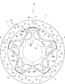
図1乃至図5を参照して説明すれば、Aは、本発明のフローティング型ディスクブレーキである(図1では、フローティング型ディスクブレーキAを正面側から示している)。このフローティング型ディスクブレーキAは、ローター1と、このローター1の内側に配置されるハブ2とから構成される。
Referring to FIGS. 1 to 5, A is a floating disc brake of the present invention (in FIG. 1, the floating disc brake A is shown from the front side). The floating disc brake A is composed of a
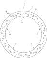
図2に示すように、ローター1は、ステンレスなどの耐磨耗性を有する金属材料から構成され、平板で環状に形成されている。このローター1の軸方向の面11には、例えば制動性能の向上や重量軽減を図るために、円形の貫通孔12が複数形成されている。
As shown in FIG. 2, the
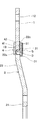
図3に示すように、ハブ2は、ステンレスやアルミ合金などの制動時の荷重に耐え得る金属材料から形成され、フローティング型ディスクブレーキAの軽量化のために平板で略星形に形成して5軸仕様としている。この場合、ハブ2は、図示しない車軸への装着を可能とする平板で環状の基部21と、所定の間隔を置いて各基部21から半径方向外側に向かって延出させた断面略台形状の5本の軸部22とから構成され、この軸部22は、ディスクブレーキAの背面側に向かって屈曲させている(図4参照)。また、主として重量軽減を図るために、各軸部22の軸方向の面22aには貫通孔22bがそれぞれ形成されている。
As shown in FIG. 3, the
ここで、例えば悪路走行時にローター1から受けるハブ2への衝撃を緩和すると共に熱引け性能を向上させるために、ローター1を、付勢手段によって半径方向外側に向かって付勢した状態でハブ2にローター1を連結するのがよいが、フローティング型ディスクブレーキAの軽量化が可能であって組立作業が容易であるようにする必要がある。
Here, for example, in order to alleviate the impact on the
本実施の形態では、ハブ2の各軸部22の外周縁部に、半径方向の凹部22cを形成すると共に、各凹部22cに対応してローター1の内周縁部に、その半径方向内側に向かって突出する5個の突出部13を形成した。この場合、突出部13の板厚はローター1と同じであり、その半径方向の高さは、凹部22cに嵌挿したときローター1を半径方向外側に付勢する後述の付勢手段3が介在できるように定寸されている。
In the present embodiment, the
そして、各突出部13を各凹部22cに嵌挿させつつローター1の内側にハブ2を組み付けた後、各突出部13の先端と各凹部22cの底面との間に付勢手段3をそれぞれ介在させ、この状態でローター1とハブ2とを軸方向に規制する規制手段4を設け、付勢手段3による半径方向外側へのローター1の付勢と、ローター1の軸方向の抜け止めが行なわれるようにハブ2にローター1を連結した。
Then, after the
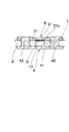
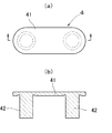
図4乃至図6に示すように、規制手段4は、ローター1の突出部13をハブ2の凹部22cに嵌挿した領域を軸方向から覆って少なくともハブ2の軸方向の面22aと面接触する板状部41と、この板状部41から軸方向に延出させた2本の円筒形状の柱状部42とから構成されている。そして、凹部22cを挟む両側に位置してハブ2に、柱状部42の外形に対応した開口22dを設け、この開口22dに軸方向からこの柱状部42を貫通させ、その先端をかしめてなる。
As shown in FIGS. 4 to 6, the restricting means 4 covers at least the
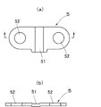
また、図4及び図5に示すように、柱上部42の挿入方向と反対側(フローティング型ディスクブレーキAの裏面)には、ローター1の突出部13をハブ2の凹部22cに嵌挿した領域を軸方向から覆って少なくともハブ2の軸方向の面22aと面接触する押さえ板5が設けられる。図7に示すように、押さえ板5の略中央部には、付勢手段である後述の板ばね3のフランジ部が収納される凹溝51が形成され、押さえ板5がハブ2の軸方向の面に面接触するようにしている。また、押さえ板5には、各柱状部42が貫通する2個の開口52が形成されている。
Further, as shown in FIGS. 4 and 5, a region where the protruding
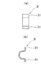
図8に示すように、付勢手段は、略U字状に成形した板ばね3であり、その両自由端は水平に屈曲されてフランジ部31が形成されている。板ばね3は、そのU字状に成形した部分から、突出部13の先端と凹部22cの底面との間に軸方向から挿入され、フランジ部31が、突出部13の軸方向の面11及び軸部22の軸方向の面22aの少なくとも一方に当接すると位置決めされるようにしている。この場合、U字状に屈曲させた部分が挿入方向と反対側に突出しないように、板ばね3の高さが定寸されている。
As shown in FIG. 8, the urging means is a
突出部13の板厚はハブ2の板厚より小さく設定している。これにより、ローター1が、規制手段4の板状部41と押さえ板5との間で軸方向に移動自在、即ち、フローティング自在となる。この場合、突出部13の板厚のみを小さくしてもよい。
The plate thickness of the protruding
これにより、板ばね3によって、ローター1に半径方向外側に向かって付勢力を作用させることで、例えば悪路走行時の上下方向の振動が吸収でき、ハブ2への衝撃を緩和できる。また、ブレーキパッドに挟まれたときになじみがよくなり、熱歪が生じ難い。さらに、ローター1は、軸方向に付勢されていないので、ブレーキパッドに対するローター1の追従性がよく、その上、ブレーキディスクAの振れ精度の修正が不要で、その上、ローター1の回転中にブレーキパッドと接触することが防止できる。
Accordingly, by applying a biasing force to the
次に、図9を参照して本発明のフローティング型ディスクブレーキAの組立を説明する。先ず規制手段4を、その板状部41を下側にして設置し、ハブ2をその背面側を上にし、各規制手段4の各柱状部42に、ハブ2に設けた各開口22dを差し込むようにして設置する。次いで、ハブ2の外側に、各軸部22の凹部22cにローター1の各突出部13をそれぞれ嵌挿させつつローター1をその背面側を上にして設置する。この場合、ハブ2に対してローター1が同心となるように精度よく位置決めしておく必要はない。
Next, the assembly of the floating type disc brake A of the present invention will be described with reference to FIG. First, the regulating means 4 is installed with its plate-
次いで、各突出部13の先端と各凹部22cの底面との間にその上方から板ばね3をそれぞれ嵌め込む。この場合、フランジ部31が、各突出部13の軸方向の面11及び各軸部22の軸方向の面22aに当接すると、板ばね3が位置決めされると共に、ハブ2に対してローター1が位置決めされるようになる。
Next, the
次いで、ハブ2から上方に突出した規制手段4の柱状部42に、押さえ板5の各開口52を差し込むようにして押さえ板5を設置する。この場合、板ばね3のフランジ部31が凹溝51に収納されるようになる。そして、押さえ板5から突出した柱状部42の先端部分をプレスかしめによりかしめる。これにより、ハブ2にローター1が連結される。
Next, the
尚、本実施の形態では、5軸仕様のものについて説明したが、これに限定されるものではなく、その軸数は任意に設定することができる。 In the present embodiment, the five-axis specification has been described, but the present invention is not limited to this, and the number of axes can be arbitrarily set.
A フローティング型ディスクブレーキ
1 ローター
13 突出部
2 ハブ
22 軸部
22c 凹部
3 板ばね(付勢手段)
4 規制手段
5 押さえ板
A Floating
4 Control means 5 Presser plate
Claims (5)
Priority Applications (1)
| Application Number | Priority Date | Filing Date | Title |
|---|---|---|---|
| JP2004106392A JP4462537B2 (en) | 2004-03-31 | 2004-03-31 | Floating disc brake |
Applications Claiming Priority (1)
| Application Number | Priority Date | Filing Date | Title |
|---|---|---|---|
| JP2004106392A JP4462537B2 (en) | 2004-03-31 | 2004-03-31 | Floating disc brake |
Publications (2)
| Publication Number | Publication Date |
|---|---|
| JP2005291336A true JP2005291336A (en) | 2005-10-20 |
| JP4462537B2 JP4462537B2 (en) | 2010-05-12 |
Family
ID=35324499
Family Applications (1)
| Application Number | Title | Priority Date | Filing Date |
|---|---|---|---|
| JP2004106392A Expired - Fee Related JP4462537B2 (en) | 2004-03-31 | 2004-03-31 | Floating disc brake |
Country Status (1)
| Country | Link |
|---|---|
| JP (1) | JP4462537B2 (en) |
Cited By (6)
| Publication number | Priority date | Publication date | Assignee | Title |
|---|---|---|---|---|
| JP2009533620A (en) * | 2006-04-13 | 2009-09-17 | クノル−ブレムゼ ジステーメ フューア ヌッツファールツォイゲ ゲゼルシャフト ミット ベシュレンクテル ハフツング | brake disc |
| EP2128476A1 (en) | 2008-05-28 | 2009-12-02 | Yamaha Hatsudoki Kabushiki Kaisha | Floating type disc brake |
| JP2011075105A (en) * | 2010-11-15 | 2011-04-14 | Honda Motor Co Ltd | Brake structure of wheel rotation device |
| JP2013053738A (en) * | 2011-09-06 | 2013-03-21 | Yutaka Giken Co Ltd | Floating type brake disk |
| EP3203103A1 (en) * | 2016-01-08 | 2017-08-09 | Triumph Designs Limited | Brake disc |
| CN112585373A (en) * | 2018-03-26 | 2021-03-30 | 沃尔沃卡车集团 | Brake disc device for vehicle |
-
2004
- 2004-03-31 JP JP2004106392A patent/JP4462537B2/en not_active Expired - Fee Related
Cited By (7)
| Publication number | Priority date | Publication date | Assignee | Title |
|---|---|---|---|---|
| JP2009533620A (en) * | 2006-04-13 | 2009-09-17 | クノル−ブレムゼ ジステーメ フューア ヌッツファールツォイゲ ゲゼルシャフト ミット ベシュレンクテル ハフツング | brake disc |
| EP2128476A1 (en) | 2008-05-28 | 2009-12-02 | Yamaha Hatsudoki Kabushiki Kaisha | Floating type disc brake |
| JP2011075105A (en) * | 2010-11-15 | 2011-04-14 | Honda Motor Co Ltd | Brake structure of wheel rotation device |
| JP2013053738A (en) * | 2011-09-06 | 2013-03-21 | Yutaka Giken Co Ltd | Floating type brake disk |
| EP3203103A1 (en) * | 2016-01-08 | 2017-08-09 | Triumph Designs Limited | Brake disc |
| CN112585373A (en) * | 2018-03-26 | 2021-03-30 | 沃尔沃卡车集团 | Brake disc device for vehicle |
| US11480226B2 (en) | 2018-03-26 | 2022-10-25 | Volvo Truck Corporation | Brake disc arrangement for a vehicle |
Also Published As
| Publication number | Publication date |
|---|---|
| JP4462537B2 (en) | 2010-05-12 |
Similar Documents
| Publication | Publication Date | Title |
|---|---|---|
| CN100365312C (en) | Laminated shim for disc brake and pad unit having same | |
| US7669699B2 (en) | Brake caliper | |
| JP6178342B2 (en) | Automotive disc brake pad retainer | |
| US6269915B1 (en) | Pad clip for a disc brake | |
| KR940003908B1 (en) | Springs for disc brakes and disc brakes with this spring | |
| JP2012519806A (en) | brake disc | |
| JP2006010079A (en) | Brake assembly | |
| KR20180094222A (en) | Brake caliper assembly | |
| JP4462537B2 (en) | Floating disc brake | |
| KR960008106A (en) | Clutch disc subassembly, manufacturing method thereof and assembly jig | |
| TWI689434B (en) | Friction pad assembly for disc brake | |
| US8844699B2 (en) | Clutch assembly with wear compensation | |
| JP4423236B2 (en) | Floating disc brake | |
| JP6649204B2 (en) | Floating brake disc | |
| EP1672239B1 (en) | Retention spring for brake pressure pads | |
| JP4423176B2 (en) | Floating brake disc | |
| CN207777467U (en) | Disk brake friction lining assembly | |
| CN102007312A (en) | Clutch disc, in particular for a motor vehicle clutch | |
| EP4071376A1 (en) | Brake assembly | |
| JP2010270894A (en) | Disc brake | |
| JP2009216195A (en) | Floating caliper type disc brake | |
| JP4204256B2 (en) | Floating brake disc | |
| EP1780437B1 (en) | Flat spring for brake pads used in disc brakes, in particular for industrial vehicles | |
| JP2009518213A (en) | Vehicle wheel cover, vehicle wheel cover holding system, and manufacturing method thereof | |
| JP6595420B2 (en) | Brake disc mounting structure |
Legal Events
| Date | Code | Title | Description |
|---|---|---|---|
| A621 | Written request for application examination |
Free format text: JAPANESE INTERMEDIATE CODE: A621 Effective date: 20070118 |
|
| RD04 | Notification of resignation of power of attorney |
Free format text: JAPANESE INTERMEDIATE CODE: A7424 Effective date: 20081121 |
|
| A977 | Report on retrieval |
Free format text: JAPANESE INTERMEDIATE CODE: A971007 Effective date: 20090326 |
|
| A131 | Notification of reasons for refusal |
Free format text: JAPANESE INTERMEDIATE CODE: A131 Effective date: 20090331 |
|
| A521 | Request for written amendment filed |
Free format text: JAPANESE INTERMEDIATE CODE: A523 Effective date: 20090422 |
|
| TRDD | Decision of grant or rejection written | ||
| A01 | Written decision to grant a patent or to grant a registration (utility model) |
Free format text: JAPANESE INTERMEDIATE CODE: A01 Effective date: 20100209 |
|
| A01 | Written decision to grant a patent or to grant a registration (utility model) |
Free format text: JAPANESE INTERMEDIATE CODE: A01 |
|
| A61 | First payment of annual fees (during grant procedure) |
Free format text: JAPANESE INTERMEDIATE CODE: A61 Effective date: 20100212 |
|
| FPAY | Renewal fee payment (event date is renewal date of database) |
Free format text: PAYMENT UNTIL: 20130226 Year of fee payment: 3 |
|
| R150 | Certificate of patent or registration of utility model |
Ref document number: 4462537 Country of ref document: JP Free format text: JAPANESE INTERMEDIATE CODE: R150 Free format text: JAPANESE INTERMEDIATE CODE: R150 |
|
| FPAY | Renewal fee payment (event date is renewal date of database) |
Free format text: PAYMENT UNTIL: 20130226 Year of fee payment: 3 |
|
| FPAY | Renewal fee payment (event date is renewal date of database) |
Free format text: PAYMENT UNTIL: 20140226 Year of fee payment: 4 |
|
| R250 | Receipt of annual fees |
Free format text: JAPANESE INTERMEDIATE CODE: R250 |
|
| R250 | Receipt of annual fees |
Free format text: JAPANESE INTERMEDIATE CODE: R250 |
|
| R250 | Receipt of annual fees |
Free format text: JAPANESE INTERMEDIATE CODE: R250 |
|
| R250 | Receipt of annual fees |
Free format text: JAPANESE INTERMEDIATE CODE: R250 |
|
| R250 | Receipt of annual fees |
Free format text: JAPANESE INTERMEDIATE CODE: R250 |
|
| R250 | Receipt of annual fees |
Free format text: JAPANESE INTERMEDIATE CODE: R250 |
|
| R250 | Receipt of annual fees |
Free format text: JAPANESE INTERMEDIATE CODE: R250 |
|
| R250 | Receipt of annual fees |
Free format text: JAPANESE INTERMEDIATE CODE: R250 |
|
| R250 | Receipt of annual fees |
Free format text: JAPANESE INTERMEDIATE CODE: R250 |
|
| R250 | Receipt of annual fees |
Free format text: JAPANESE INTERMEDIATE CODE: R250 |
|
| LAPS | Cancellation because of no payment of annual fees |