JP2006010079A - Brake assembly - Google Patents
Brake assembly Download PDFInfo
- Publication number
- JP2006010079A JP2006010079A JP2005183202A JP2005183202A JP2006010079A JP 2006010079 A JP2006010079 A JP 2006010079A JP 2005183202 A JP2005183202 A JP 2005183202A JP 2005183202 A JP2005183202 A JP 2005183202A JP 2006010079 A JP2006010079 A JP 2006010079A
- Authority
- JP
- Japan
- Prior art keywords
- brake
- pad
- brake pad
- caliper
- brake assembly
- Prior art date
- Legal status (The legal status is an assumption and is not a legal conclusion. Google has not performed a legal analysis and makes no representation as to the accuracy of the status listed.)
- Ceased
Links
Images


Classifications
-
- F—MECHANICAL ENGINEERING; LIGHTING; HEATING; WEAPONS; BLASTING
- F16—ENGINEERING ELEMENTS AND UNITS; GENERAL MEASURES FOR PRODUCING AND MAINTAINING EFFECTIVE FUNCTIONING OF MACHINES OR INSTALLATIONS; THERMAL INSULATION IN GENERAL
- F16D—COUPLINGS FOR TRANSMITTING ROTATION; CLUTCHES; BRAKES
- F16D65/00—Parts or details
- F16D65/02—Braking members; Mounting thereof
- F16D65/04—Bands, shoes or pads; Pivots or supporting members therefor
- F16D65/092—Bands, shoes or pads; Pivots or supporting members therefor for axially-engaging brakes, e.g. disc brakes
-
- F—MECHANICAL ENGINEERING; LIGHTING; HEATING; WEAPONS; BLASTING
- F16—ENGINEERING ELEMENTS AND UNITS; GENERAL MEASURES FOR PRODUCING AND MAINTAINING EFFECTIVE FUNCTIONING OF MACHINES OR INSTALLATIONS; THERMAL INSULATION IN GENERAL
- F16D—COUPLINGS FOR TRANSMITTING ROTATION; CLUTCHES; BRAKES
- F16D55/00—Brakes with substantially-radial braking surfaces pressed together in axial direction, e.g. disc brakes
- F16D55/02—Brakes with substantially-radial braking surfaces pressed together in axial direction, e.g. disc brakes with axially-movable discs or pads pressed against axially-located rotating members
- F16D55/22—Brakes with substantially-radial braking surfaces pressed together in axial direction, e.g. disc brakes with axially-movable discs or pads pressed against axially-located rotating members by clamping an axially-located rotating disc between movable braking members, e.g. movable brake discs or brake pads
- F16D55/224—Brakes with substantially-radial braking surfaces pressed together in axial direction, e.g. disc brakes with axially-movable discs or pads pressed against axially-located rotating members by clamping an axially-located rotating disc between movable braking members, e.g. movable brake discs or brake pads with a common actuating member for the braking members
- F16D55/225—Brakes with substantially-radial braking surfaces pressed together in axial direction, e.g. disc brakes with axially-movable discs or pads pressed against axially-located rotating members by clamping an axially-located rotating disc between movable braking members, e.g. movable brake discs or brake pads with a common actuating member for the braking members the braking members being brake pads
- F16D55/226—Brakes with substantially-radial braking surfaces pressed together in axial direction, e.g. disc brakes with axially-movable discs or pads pressed against axially-located rotating members by clamping an axially-located rotating disc between movable braking members, e.g. movable brake discs or brake pads with a common actuating member for the braking members the braking members being brake pads in which the common actuating member is moved axially, e.g. floating caliper disc brakes
-
- F—MECHANICAL ENGINEERING; LIGHTING; HEATING; WEAPONS; BLASTING
- F16—ENGINEERING ELEMENTS AND UNITS; GENERAL MEASURES FOR PRODUCING AND MAINTAINING EFFECTIVE FUNCTIONING OF MACHINES OR INSTALLATIONS; THERMAL INSULATION IN GENERAL
- F16D—COUPLINGS FOR TRANSMITTING ROTATION; CLUTCHES; BRAKES
- F16D55/00—Brakes with substantially-radial braking surfaces pressed together in axial direction, e.g. disc brakes
- F16D55/24—Brakes with substantially-radial braking surfaces pressed together in axial direction, e.g. disc brakes with a plurality of axially-movable discs, lamellae, or pads, pressed from one side towards an axially-located member
- F16D55/26—Brakes with substantially-radial braking surfaces pressed together in axial direction, e.g. disc brakes with a plurality of axially-movable discs, lamellae, or pads, pressed from one side towards an axially-located member without self-tightening action
- F16D55/36—Brakes with a plurality of rotating discs all lying side by side
-
- F—MECHANICAL ENGINEERING; LIGHTING; HEATING; WEAPONS; BLASTING
- F16—ENGINEERING ELEMENTS AND UNITS; GENERAL MEASURES FOR PRODUCING AND MAINTAINING EFFECTIVE FUNCTIONING OF MACHINES OR INSTALLATIONS; THERMAL INSULATION IN GENERAL
- F16D—COUPLINGS FOR TRANSMITTING ROTATION; CLUTCHES; BRAKES
- F16D55/00—Brakes with substantially-radial braking surfaces pressed together in axial direction, e.g. disc brakes
- F16D2055/0004—Parts or details of disc brakes
- F16D2055/0016—Brake calipers
- F16D2055/002—Brake calipers assembled from a plurality of parts
-
- F—MECHANICAL ENGINEERING; LIGHTING; HEATING; WEAPONS; BLASTING
- F16—ENGINEERING ELEMENTS AND UNITS; GENERAL MEASURES FOR PRODUCING AND MAINTAINING EFFECTIVE FUNCTIONING OF MACHINES OR INSTALLATIONS; THERMAL INSULATION IN GENERAL
- F16D—COUPLINGS FOR TRANSMITTING ROTATION; CLUTCHES; BRAKES
- F16D2250/00—Manufacturing; Assembly
- F16D2250/0084—Assembly or disassembly
Landscapes
- Engineering & Computer Science (AREA)
- General Engineering & Computer Science (AREA)
- Mechanical Engineering (AREA)
- Braking Arrangements (AREA)
Abstract
Description
本発明はブレーキ組立体に関し、特に、トラック、大型トラック、バスなどの重量路上走行車両に使用する摺動キャリパブレーキ組立体又は摺動ディスクを備えるブレーキ組立体に関する。 The present invention relates to a brake assembly, and more particularly, to a sliding caliper brake assembly or a brake assembly including a sliding disk for use on a heavy road vehicle such as a truck, a large truck, or a bus.
自動二輪車及び乗用車用のブレーキキャリパは比較的軽量であり、そのため1人でも容易に扱うことができる。したがって、磨耗したブレーキパッドを交換する際、ブレーキキャリパを取り外し、次いで磨耗したブレーキパッドを新しいブレーキパッドと交換し、その後ブレーキキャリパを元の位置に戻すという設計が可能である。このような構成が米国特許第4200173号に示されている。 Brake calipers for motorcycles and passenger cars are relatively lightweight and can be easily handled by one person. Thus, when replacing worn brake pads, it is possible to remove the brake caliper, then replace the worn brake pad with a new brake pad, and then return the brake caliper to its original position. Such an arrangement is shown in U.S. Pat. No. 4,200,193.
重量路上走行車両用の摺動キャリパブレーキは、必然的にそれ自体が重くなる。通常は、摺動キャリパだけ(連結されるキャリアなしで)でも非常に重くなり、例えば、磨耗したブレーキパッドを新しいブレーキパッドと交換する作業中に、1人だけで持ち上げるのは危険である。このため、周知の重量車両用摺動キャリパブレーキ組立体は、それぞれがキャリパの作動装置側を反作用側に連結する、周方向に間隔を置いて配置された2つの架橋腕部を含み、それによって窓が画定され、そこから磨耗したブレーキパッドを取り外し、そこから新しいブレーキパッドを挿入することができる。この種の構成では、摺動キャリパを取り外す必要はない。欧州特許第0906856号がまさにこのような構成を示している。 A sliding caliper brake for a vehicle traveling on a heavy road inevitably becomes heavier. Normally, even a sliding caliper alone (without a coupled carrier) can be very heavy, and it is dangerous to lift alone, for example, when replacing a worn brake pad with a new brake pad. For this reason, known heavy vehicle sliding caliper brake assemblies include two circumferentially spaced bridging arms each connecting the caliper actuating device side to the reaction side, thereby A window is defined from which the worn brake pad can be removed and a new brake pad can be inserted therefrom. With this type of configuration, it is not necessary to remove the sliding caliper. EP 0906856 shows just such a configuration.
工具(tooling)コストを削減するとともに量産による利益を得るために、ブレーキ組立体用の部品の種類を最少に抑えることは、製造業者にとって有利である。さらに、キャリパをより少ない種類の部品で設計することで、予備部品の貯蔵の点でも利益がある。保守部材、すなわち関連する車両の耐用期間を通じて、適切な保守期間ごとに通常交換を必要とする部材用の部品の種類を最少に抑えることは特に有利である。したがって、ブレーキ製造業者は、ブレーキ組立体用の2つのブレーキパッドを同一にしたブレーキ組立体を設計することが多い。車両の車軸を考えると、車軸の右側端部のキャリパは、車軸の左側端部のキャリパの鏡像(mirror image)であることが多く、これはすなわち、車軸上の4つのブレーキパッドすべてを同一にすることが可能であるということである。米国特許第4200173号、欧州特許第0906856号、及び同第0752541号は、同一のブレーキパッドの対を備えるブレーキキャリパの例を示す。すなわち、ブレーキパッドは互いに交換可能である。したがって、特定のブレーキパッドをブレーキディスクの車体内側又は車体外側にはめ込み、他方のブレーキパッドをブレーキディスクの車体内側又は車体外側の他方にはめ込むことができる。 In order to reduce tooling costs and gain the benefits of mass production, it is advantageous for manufacturers to minimize the types of parts for brake assemblies. In addition, designing the caliper with fewer types of parts is also beneficial in terms of storing spare parts. It is particularly advantageous to minimize the types of parts for maintenance members, i.e. parts that normally require replacement every appropriate maintenance period, throughout the life of the associated vehicle. Therefore, brake manufacturers often design brake assemblies that have the same two brake pads for the brake assembly. Considering the vehicle axle, the caliper at the right end of the axle is often a mirror image of the caliper at the left end of the axle, which means that all four brake pads on the axle are identical. It is possible to do. U.S. Pat. No. 4,200,193, European Patent Nos. 0906856 and 0752541 show examples of brake calipers with identical pairs of brake pads. That is, the brake pads are interchangeable. Therefore, a specific brake pad can be fitted to the inside of the vehicle body or the outside of the vehicle body of the brake disc, and the other brake pad can be fitted to the other inside of the vehicle body of the brake disc or the outside of the vehicle body.
これに対して、米国特許第5343985号は、車体外側の単一のブレーキパッドを、車体内側のより小型のブレーキパッドの対と交換できない例を示している。
ブレーキキャリパのこれらのブレーキパッドは、キャリパの両側から作動させ、又は片側から作動させることができる。
In contrast, US Pat. No. 5,343,985 shows an example where a single brake pad on the outside of the vehicle body cannot be replaced with a pair of smaller brake pads on the inside of the vehicle body.
These brake pads of the brake caliper can be actuated from both sides of the caliper or from one side.
前者の例では、ブレーキキャリパは、車体内側に1つ又は複数の油圧作動式ピストンを備え、同じ数の油圧作動式ピストンを車体外側にも備える。このような状況では、キャリパは、懸架装置構成部品に軸方向に固定され、ブレーキディスクもまた、別の懸架装置構成部品に軸方向に固定される。ブレーキが作動すると、作動油によって車体内側の1つ又は複数のピストンが外側に移動し、それによって車体内側のブレーキパッドがブレーキディスクに押し付けられると同時に、車体外側の1つ又は複数のピストンが内側に移動し、それによって車体外側ブレーキパッドがブレーキディスクに押し付けられることになる。 In the former example, the brake caliper includes one or more hydraulically operated pistons on the inner side of the vehicle body, and includes the same number of hydraulically operated pistons on the outer side of the vehicle body. In such a situation, the caliper is fixed axially to the suspension component and the brake disc is also fixed axially to another suspension component. When the brake is activated, one or more pistons inside the vehicle body are moved outward by the hydraulic fluid, thereby pressing the brake pads inside the vehicle body against the brake disc and at the same time one or more pistons outside the vehicle body This causes the vehicle body outer brake pad to be pressed against the brake disc.
一方、米国特許第4200173号、欧州特許第0906856号、同第0752541号、及び米国特許第5343985号はすべて、片側から作動されるブレーキキャリパの例を示す。どの場合でも、作動装置はブレーキディスクの車体内側に取り付けられることになる。これらの例はどれも、ブレーキディスクの車体外側には作動装置を備えていないので、キャリパの車体外側は比較的コンパクトであり、したがって、車体外側にも作動装置を有する同等のキャリパの場合に比べて車輪内で外被(envelope)が占める空間が小さくなることが理解されよう。 On the other hand, U.S. Pat. No. 4,200,193, European Patent Nos. 0906856, 0752541, and U.S. Pat. No. 5,343,985 all show examples of brake calipers operated from one side. In any case, the actuating device will be mounted inside the body of the brake disc. None of these examples have an actuator on the outside of the brake disc body, so the outside of the caliper body is relatively compact, so compared to an equivalent caliper with an actuator on the outside of the body. It will be appreciated that the space occupied by the envelope within the wheel is reduced.
米国特許第4200173号、欧州特許第0906856号、同第0752541号、及び米国特許第5343985号はすべて摺動キャリパブレーキの例である。したがって、キャリパは、通常はピン上で、(連結されるブレーキディスクの回転軸線から考えて)軸方向に摺動することができる。このため、ブレーキがかけられると、ブレーキキャリパはわずかに車体内側に移動して、ブレーキディスクと車体外側ブレーキパッドの間の移動隙間(running clearance)がなくなり、それによって車体外側ブレーキパッドがブレーキディスクと摩擦係合することになる。さらに、車体外側ブレーキパッドが磨耗するにつれて、キャリパの通常の移動位置(running position)(すなわち、ブレーキがかけられていないときのキャリパ位置)は、車体外側ブレーキパッドとブレーキディスクの間の移動隙間を維持するために次第に軸方向内側に移動することになる。 U.S. Pat. No. 4,200,193, European Patent Nos. 0906856, 0752541, and U.S. Pat. No. 5,343,985 are all examples of sliding caliper brakes. Therefore, the caliper can slide in the axial direction (considering the rotation axis of the connected brake disc), usually on the pin. For this reason, when the brake is applied, the brake caliper moves slightly inward of the vehicle body, and there is no moving clearance between the brake disc and the vehicle body outer brake pad. Friction engagement will occur. In addition, as the vehicle body outer brake pads wear, the caliper's normal running position (ie, the caliper position when the brakes are not applied) will cause the movement gap between the vehicle body outer brake pads and the brake discs to increase. To maintain it, it will gradually move inward in the axial direction.
また、上述の「摺動キャリパ」設計とは違って、キャリパが懸架装置構成部品に軸方向に固定された、片側から作動されるキャリパを備えることも可能である。しかし、片側から作動される、軸方向に固定されたキャリパには摺動ブレーキディスクが必要になる。これは、車体外側ブレーキパッドがキャリパに軸方向に固定され、キャリパもまた上述のように軸方向に固定されるので、車体外側ブレーキパッドとディスクの間の移動隙間をなくすために、ディスクが車体外側ブレーキパッドの方に移動できなければならないからである。片側から作動させる作動装置を備える摺動ディスクブレーキは知られている。 Also, unlike the “sliding caliper” design described above, it is possible to provide a caliper that is actuated from one side, the caliper being fixed axially to the suspension component. However, an axially fixed caliper operated from one side requires a sliding brake disc. This is because the vehicle body outside brake pad is fixed to the caliper in the axial direction, and the caliper is also fixed in the axial direction as described above. Therefore, in order to eliminate the movement gap between the vehicle body outside brake pad and the disc, This is because it must be able to move toward the outer brake pad. Sliding disc brakes with an actuating device that operates from one side are known.
周知のブレーキキャリパのブレーキパッドは、摩擦材料がその上に結合又はその他の方法で固定された鋼製ブレーキパッド背板を備える。摩擦材料は、制動中そこに接して係合するブレーキディスクに対応するように通常は円弧形である(例えば米国特許第4200173号、欧州特許第0906856号、同第0752541号、及び米国特許第5343985号参照のこと)。したがって、ブレーキパッド背板もやはりほぼ円弧形であり、周方向に各端部を有する。ブレーキがかけられたとき、制動トルク負荷(接線方向負荷とも呼ばれる)がブレーキパッドから懸架装置を介して車両に伝達されなければならない。米国特許第4200173号及び欧州特許第0752541号は、車体内側と車体外側の両方のブレーキパッドの制動トルク負荷が、車両車軸又は他の同等の懸架装置構成部品にしっかりと固定されたブレーキキャリアに伝達される例を示す。注目すべきことに、制動トルク負荷は、摺動キャリパを介しては伝達されず、したがって、摺動キャリパがその上で摺動するピンは、制動トルク負荷をまったく受けない。しかし、米国特許第4200173号も欧州特許第0752541号も、ブレーキディスクの車体外側で軸方向に固定された、ブレーキがかけられたときにブレーキトルク負荷を伝達するための構造と、ブレーキディスクの車体外側で軸方向に摺動可能な、ブレーキがかけられたときにキャリパによってブレーキパッドに締付け負荷が加えられるようにする構造とを必要とする。したがって、ブレーキディスクの車体外側には、軸方向に固定された構造と軸方向に摺動可能な構造とを収容する適当な囲い空間を設けなければならないが、この空間は元来、連結される車輪リムが近接するために限られている。 Known brake caliper brake pads include a steel brake pad backplate onto which friction material is bonded or otherwise secured. The friction material is usually arcuate to accommodate a brake disk that contacts and engages it during braking (eg, US Pat. No. 4,200,143, European Patent Nos. 0906856, 0752541, and US Pat. No. 5343985). Therefore, the brake pad back plate is also substantially arc-shaped and has each end in the circumferential direction. When the brake is applied, a braking torque load (also called a tangential load) must be transmitted from the brake pad to the vehicle via the suspension. U.S. Pat. No. 4,200,193 and European Patent No. 0752541 transmit the braking torque load on both the inside and outside body brake pads to a brake carrier that is firmly fixed to the vehicle axle or other equivalent suspension component. An example is shown. It should be noted that the braking torque load is not transmitted through the sliding caliper, so the pin on which the sliding caliper slides is not subjected to any braking torque load. However, both U.S. Pat. No. 4,200,193 and European Patent No. 0752541 are fixed in the axial direction outside the vehicle body of the brake disc and transmit the brake torque load when the brake is applied, and the vehicle body of the brake disc. There is a need for a structure that is axially slidable on the outside and that allows the caliper to apply a tightening load to the brake pad when the brake is applied. Accordingly, an appropriate enclosure space for housing the structure fixed in the axial direction and the structure slidable in the axial direction must be provided outside the vehicle body of the brake disc. This space is originally connected. Limited due to proximity of wheel rims.
欧州特許第0906856号は、車体外側ブレーキパッドからの制動トルク負荷が摺動キャリパに伝達され、これらの制動トルク負荷が、次いでブレーキディスクの軸方向車体外側に位置する、固定されたキャリアの突起部(hug)に伝達される例を示す。 EP 0906856 discloses a fixed carrier projection in which braking torque loads from a vehicle body outer brake pad are transmitted to a sliding caliper and these braking torque loads are then located axially outside the vehicle body of the brake disc. An example transmitted to (hug) is shown.
米国特許第4200173号、欧州特許第0906856号、及び同第0752541号では、ブレーキトルク負荷は、パッドブレーキ背板の周方向各端部を介して伝達されるので、必然的に、キャリア又はキャリパのこの領域に適当な当接部を設けなければならなくなることが理解されよう。このために、キャリパ及びキャリアの設計の自由度が制限される。 In U.S. Pat. No. 4,200,193, European Patent Nos. 0906856, and 0752541, the brake torque load is transmitted through each circumferential end of the pad brake backplate, which inevitably results in the carrier or caliper. It will be appreciated that an appropriate abutment must be provided in this area. This limits the freedom of caliper and carrier design.
ブレーキキャリパのいくつかの設計に伴う周知の問題は、ブレーキパッドが逆さまにはめ込まれる、すなわち、鋼製のブレーキパッド背板がブレーキディスクに面するようにブレーキパッドがはめ込まれる恐れがあることである。誤ってはめ込まれたブレーキパッドは、明らかに危険である。欧州特許第0752541号は、ブレーキパッドが必ず正しくはめ込まれるように保証する1つの方策を提供している。 A known problem with some brake caliper designs is that the brake pads can be fitted upside down, i.e. the brake pads can be fitted so that the steel brake pad backplate faces the brake disc. . Incorrectly fitted brake pads are clearly dangerous. European Patent No. 0752541 provides one measure to ensure that the brake pads are fitted correctly.
本発明の目的は、上述の問題の1つ又は複数を軽減するブレーキ組立体を提供することである。 It is an object of the present invention to provide a brake assembly that alleviates one or more of the problems described above.
したがって、本発明によれば、添付の独立請求項に記載のブレーキ組立体が提供される。
添付の図面を参照して、本発明を単なる例によって以下に説明する。
Therefore, according to the present invention there is provided a brake assembly according to the attached independent claims.
The invention will now be described by way of example only with reference to the accompanying drawings.
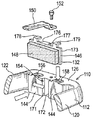
図1及び2を参照すると、摺動キャリパ12及びキャリア14を備える周知のブレーキ組立体10が示される。摺動キャリパは、作動装置組立体(図示せず)がその中に据えられる作動装置ハウジング18に固定された空気室16を備える。
Referring to FIGS. 1 and 2, a known
摺動キャリパはさらに、ブレーキディスク24の径方向外側で、周方向に間隔を置いて配置された架橋腕部20及び22を含む。摺動キャリパはさらに、架橋腕部20及び22の各端部を連結する反作用側部分26を備える。キャリパは、キャリア14のピン(図示せず)上に摺動可能に取り付けられる。
The sliding caliper further includes bridging
使用時には、キャリア14は通常、重量車両の車軸に固定される。車輪ハブが車軸端部に取り付けられ、車輪及びブレーキディスク24に回転可能に固定される。ブレーキ組立体10は、反作用側部分26が車軸の車体外側端部にあり、空気室が反作用側部分26の車体内側に位置するように構成される。したがって、作動装置筐体がブレーキディスク24の車体内側に配置され、反作用側部分26がブレーキディスク24の車体外側に配置される。作動装置ハウジング18と、架橋腕部20及び22と、反作用側部分26とがあいまって窓28を画定し、この窓から、例えば、磨耗したパッドを新しいパッドと交換する際に、作動装置側ブレーキパッド30(車体内側ブレーキパッドとも呼ばれる)及び反作用側ブレーキパッド32(車体外側ブレーキパッドとも呼ばれる)の挿入又は取外しが可能になる。
In use, the
図2に移ると、キャリア14のより詳細な部品が示される。キャリア14は、周方向に間隔を置いて配置されたキャリア腕部34及び36を含み、それらの最も車体外側の各端部が、キャリア反作用側部分38によって連結される。
Turning to FIG. 2, more detailed parts of the
キャリア反作用側部分38は、周方向に間隔を置いて配置されたトルク反作用当接部40及び41と、ほぼ径方向外側に面する径方向負荷当接部42及び43とを含む。同様のトルク反作用当接部及び径方向負荷当接部が、キャリアの作動装置側(すなわち車体内側)にも見られる。
The carrier
キャリパ反作用側部分26は、締付け負荷当接部44を含む。
反作用側ブレーキパッド32は、摩擦材料48に固定された背板46を含む。作動装置側ブレーキパッド30は、反作用側ブレーキパッド32と同一である。
The caliper
The reaction
この種の摺動キャリパブレーキの動作は、当業者には周知であるが、概略的に述べると、空気が空気室16内に流れ込み、それが仕切板に作用して、押棒が作動装置筐体18内に収容された作動装置組立体を動作させることになる。作動装置組立体は、作動装置側ブレーキパッド30の背板に作用して、作動装置側ブレーキパッドの摩擦材料をブレーキディスク24の作動装置側と係合させる働きをする2つのピストンを備える。この横方向の締付け負荷力によって同等の反対方向の反作用力が生じ、その結果、キャリパ反作用側部分の締付け負荷当接部44が背板46に作用して、摩擦材料48をブレーキディスク24の反作用側面と係合させるまで、摺動キャリパがそのピン上で車体内側に摺動する。次いで、ブレーキディスク24が2つのブレーキパッドの間で挟持され、車体外側パッドに加えられた摩擦トルクが、ブレーキディスク24の回転方向に応じてキャリアのトルク反作用当接部40又は41のいずれかに直接伝達される。同様に、作動装置側ブレーキパッドに加えられた摩擦トルクが、ディスクの車体内側にあるキャリアの同等のトルク反作用当接部に伝達される。
The operation of this type of sliding caliper brake is well known to those skilled in the art, but generally speaking, air flows into the
理想的には、ブレーキ組立体10は、窓28が関連する車両に対してほぼ上側に面するように取り付けられる。したがって、径方向負荷当接部42及び43が、車体外側パッドの重量を支持する垂直方向の反作用負荷をもたらす。パッド保持器50がキャリパに固定され、パッドばね54が反作用側ブレーキパッド32の頂面に作用するとともに、ブレーキパッド保持器の底面にも反作用して、使用時にブレーキパッドが音を立てないように、また、窓から飛び出さないようにする。したがって、径方向負荷当接部42及び43は、パッドばね54に対して反作用するばね反作用負荷をももたらす。
Ideally, the
しかし、個々の取付け状態のために、窓28が常に上方に面するようにブレーキ組立体を取り付けることが必ずしも可能ではない。車両懸架構成部品を回避するために、ブレーキ組立体を垂直位置からどちらかの側に最高135度までずらして取り付けることが必要となる場合もある。したがって、個々の取付け状態によっては、径方向負荷当接部42及び43は、車体外側パッドの全重量には(又は場合によっては重量の一部にも)反作用しなくてもよいことがある。とはいえ、ばね負荷は、車体外側パッドの重量よりもはるかに大きいので、径方向負荷当接部42及び43は、それでもやはり反作用力をもたらすことになる。一例を挙げると、ブレーキパッドの重量を30ニュートン、取り付けられたパッドばね負荷を300ニュートンとすることができる。
However, due to individual mounting conditions, it is not always possible to mount the brake assembly so that the
概略的に述べると、この場合、キャリパが締付け負荷をもたらし、トルク負荷及び径方向(又は垂直方向)負荷がキャリアの反作用を受ける。
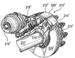
図21は、他の周知のブレーキ組立体210’を示す。この図では、ブレーキ組立体10と同じ構成部品には200’大きい番号が付されている。図21は、車両車軸211’と、キャリア214’がボルト215’によってそこに固定される方式を示す。図21はまた、車両車輪がそこにはめ込まれることになる回転ハブ213’も示す。
Generally speaking, in this case, the caliper provides a tightening load, and the torque load and radial (or vertical) load are subjected to carrier reaction.
FIG. 21 shows another known
上述のように、本発明は、特に、トラック、大型トラック、バスなどの重量路上走行車両に使用するブレーキ組立体に関する。この種のブレーキ組立体は、乗用車や自動二輪車などより軽量の車両用のブレーキ組立体に比べると、必然的に大型で重くなる。実際に、通常は、(キャリアなしで)摺動キャリパだけでも非常に重くなり、1人だけで持ち上げるのは危険である。このため、ブレーキ組立体は、ブレーキパッドが磨耗して交換が必要なときに、摺動キャリパを取り外さずに、それらパッドを取り外せるように設計されている。特に、(パッド保持器50を取り外した後は)窓28があるために、摺動キャリパ12を取り外さずにブレーキパッドを取り外すことが容易になる。
As described above, the present invention particularly relates to a brake assembly for use in a heavy road vehicle such as a truck, a heavy truck, or a bus. This type of brake assembly is inevitably larger and heavier than a brake assembly for a lighter vehicle such as a passenger car or a motorcycle. In fact, usually even a sliding caliper alone (without a carrier) is very heavy and it is dangerous to lift it alone. For this reason, the brake assembly is designed such that when the brake pads wear out and need to be replaced, they can be removed without removing the sliding calipers. In particular, because of the window 28 (after removing the pad retainer 50), it is easy to remove the brake pad without removing the sliding
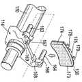
図3から6は、本発明によるブレーキ組立体の第1の実施形態110を示す。これらの図では、ブレーキ組立体10と同じ構成部品には100大きい番号が付されている。
注目すべきことに、摺動キャリパ12と摺動キャリパ112の唯一の違いは、後者が、径方向に向いた溝154と、径方向負荷当接パッド156及び158とを含むことである。
3 to 6 show a
Of note, the only difference between the sliding
図5は、摺動キャリパのいくつかの構成部品をさらに詳細に示す。この図では、周方向に間隔を置いて配置された2つの作動装置ピストン160(タペット組立体とも呼ばれる)が、作動装置筐体118から車体外側方向に突き出しているのが分かる。2つのピストン160の周方向の間隔によって、それらの間に凹部165が画定される。さらに、図5は、キャリパがキャリア114のピン163及び164上でそれぞれ摺動できるようになる、孔161及び162も示す。
FIG. 5 shows some components of the sliding caliper in more detail. In this figure, it can be seen that two actuator pistons 160 (also referred to as tappet assemblies) spaced apart in the circumferential direction protrude from the
キャリア114は、車体内側(すなわち作動装置側)トルク反作用当接部166及び167と、車体内側(作動装置側)径方向負荷当接部168及び169とを含む。トルク反作用当接部166及び167は、ブレーキパッドの対応する周方向端部173及び174と係合する。キャリア114は、車軸170に回転可能にしっかりと固定される。注目すべきことに、キャリア114は、キャリア14のキャリア腕部34及び36を含まない。さらに、キャリア114は、キャリア反作用側部分38及び関連する当接部を含まない。
The
要するに、車体外側ブレーキパッドに関しては、キャリア14のトルク反作用当接部40及び41の機能は、キャリパ112の径方向に向いた溝154によって果たされ、キャリア14の径方向負荷当接部42及び43の機能は、キャリパ112の径方向負荷当接部156及び158によって果たされる。
In short, with respect to the vehicle body outside brake pad, the functions of the torque
注目すべきことに、車体内側ブレーキパッドに関しては、ブレーキトルク負荷は、やはりブレーキパッドの周方向各端部によりキャリアに伝達される。
より詳細には、径方向に向いた溝154は、その周方向の一方の側にトルク反作用当接部171を有し、さらにその周方向の他方の側にもう1つのトルク反作用当接部172を有する。
It should be noted that with respect to the vehicle body inner side brake pad, the brake torque load is also transmitted to the carrier by each circumferential end of the brake pad.
More specifically, the radially oriented
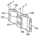
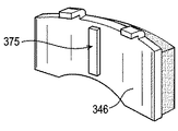
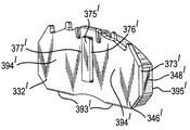
図6は、車体外側ブレーキパッド132のブレーキパッド背板146を示す。この背板は、周方向端部173及び174を有し、ほぼ円弧形である。径方向に向いたリブ175の形の第1の構成体が、周方向端部173及び174から離れて形成される。リブ175は、周方向に間隔を置いて配置された縁部176及び177を含み、それらはキャリパ112に組み込む際に、それら縁部がそれぞれトルク反作用当接部171及び172に面することになる。
FIG. 6 shows the brake pad back
背板146はさらに、周方向に間隔を置いて配置された、背板の径方向外側縁部から折り曲がったタブ178及び179を有し、キャリパ112に組み込まれたとき、それらタブの径方向内側に面する表面がそれぞれ、(反作用側部分の径方向外側縁部に位置する)径方向外側に面する負荷当接パッド156及び158に当接することになる。
The
ブレーキ組立体10で締付け負荷が締付け負荷当接部44によってもたらされるのとまったく同じように、この場合は負荷が締付け負荷当接部144によってもたらされることが理解されよう。しかし、ブレーキ組立体110では、摩擦トルクは、背板146から、リブ175の縁部176又は177を介して、摺動キャリパの溝154のトルク反作用当接部171又は172に伝達される。車体外側パッドのトルク反作用負荷は、次いで、ブレーキディスクの作動装置側に位置するピン163及び164を介してキャリアに伝達される。
It will be appreciated that in this case the load is provided by the tightening
また、パッドの径方向(又は垂直方向)の負荷が、タブ178及び179を介して、キャリパ112の径方向負荷当接パッド156及び158に伝達される。これらの径方向負荷は、次いでピン163及び164を介してキャリアに伝達される。
Further, the radial load (or vertical direction) of the pad is transmitted to the radial
特に、車体外側の背板146の周方向端部173及び174は、キャリパにトルク負荷を伝達する際に何の役割も果たさない。このような構成では、キャリパの周方向端部173及び174の領域にトルク反作用当接部を設ける必要がないので、キャリパを設計する際に、この領域での自由度が増す。
In particular, the circumferential ends 173 and 174 of the
図2から考えると、車両が前進しているときにブレーキがかけられると、車体外側のブレーキパッドトルク負荷がトルク反作用当接部40に伝達されることになるが、これは、その当接部40がキャリア腕部34に相対的に近く、キャリア腕部36からは相対的に離れているので、キャリア腕部36がブレーキトルクのほとんどを車体外側ブレーキパッドから車軸に伝達することになることが分かる。逆に、車両が後進しているときにブレーキがかけられると、キャリア腕部34がブレーキトルクのほとんどを車軸に伝達することになる。図5から考えると、径方向に向いた溝154は、架橋腕部120及び122から等間隔に配置されているのが分かる。このため、これらの架橋腕部は、車体外側ブレーキパッドのトルク負荷を等しく分担して車軸に伝達する。
Considering FIG. 2, when the brake is applied while the vehicle is moving forward, the brake pad torque load on the outside of the vehicle body is transmitted to the torque
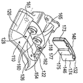
図4及び5に移ると、車体内側ブレーキパッド130は、車体外側ブレーキパッド132と同一である。しかし、この場合は、車体内側ブレーキパッド130からのトルク負荷は、ブレーキディスクの回転方向に応じて、トルク反作用当接部166及び167に適切に当接する周方向の端部173及び174によって、キャリアに直接伝達される。したがって、車体内側ブレーキパッド130の径方向に向いたリブ175は冗長である。好都合には、リブ175は、凹部165内に位置するので係合されることはなく、ピストン160の動作を妨げることはない。
4 and 5, the vehicle body
車体内側ブレーキパッド130からの径方向(垂直方向)の負荷は、背板の径方向内側縁部を介して、キャリア114の径方向負荷当接部168及び169に直接伝達される。したがって、車体内側ブレーキパッド130のタブ178及び179は冗長であるが、好都合にはピストン160の車体外側に位置し、したがって接触することはなく又はその他の方法でピストン160の動作を妨げることもない。
The load in the radial direction (vertical direction) from the vehicle body inner
他方のパッド(車体内側パッド)からのトルク負荷はキャリアに直接伝達され、キャリパを介しては伝達されないので、ピン163及び164は、一方のパッド(車体外側パッド)からのみトルク反作用負荷を受けることが理解されよう。
Since the torque load from the other pad (vehicle body inner pad) is transmitted directly to the carrier and not via the caliper, the
架橋腕部が各ブレーキパッドの長さよりも広い間隔を置いて配置されるので、車体外側パッドの径方向に向いたリブ175は、キャリパの邪魔をせずに(disturb)窓128から車体外側パッドを取り外せるように形成されることが理解されよう。同様に、車体内側パッド130も、キャリパの邪魔をせずに窓128から取り外すことができる。したがって、本発明は、摺動キャリパを取り外すか又は他の方法で邪魔をせずにブレーキパッドを取り外して交換でき、かつキャリパの車体外側ブレーキパッドの周方向各端部付近の設計を自由にできるブレーキ組立体を提供する。
Since the bridging arms are arranged at a wider interval than the length of each brake pad, the
したがって、本発明の一実施形態では、車体外側パッドの制動トルク負荷が1つの機構(feature)(径方向に向いたリブ)を介してキャリパに伝達され、車体内側パッドの制動トルク負荷が異なる機構(ブレーキパッドの周方向各端部)を介してブレーキ組立体(キャリア)に伝達される、2つの同一のブレーキパッドを有するブレーキ組立体が提供される。 Accordingly, in one embodiment of the present invention, the braking torque load on the vehicle body outer pad is transmitted to the caliper via one feature (radially oriented rib), and the braking torque load on the vehicle body inner pad is different. A brake assembly is provided having two identical brake pads that are transmitted to the brake assembly (carrier) via (each circumferential end of the brake pad).
車体外側パッドからと車体内側パッドからとで異なる方式で制動トルク負荷を伝達することによって、設計の自由度が増す。
図6〜12は、本発明で使用するブレーキパッド背板の様々な実施形態を示す。
By transmitting the braking torque load in a different manner from the vehicle body outer pad and from the vehicle body inner pad, the degree of freedom in design is increased.
6-12 show various embodiments of brake pad backplates for use with the present invention.
図6については、上記で詳細に述べた通りである。パッドの主本体部は、厚さtを有し、通常は6〜9ミリメートルである。一方、リブ領域のパッド厚Tは、通常は10〜18ミリメートルでよい。リブ175は、背板の残りの部分と一体に鋳造することができ、あるいは、別個の構成部品として形成して、好ましくは溶接又はボルトによって背板の主本体部に固定することもできる。
FIG. 6 is as described in detail above. The main body portion of the pad has a thickness t and is typically 6-9 millimeters. On the other hand, the pad thickness T in the rib region is usually 10 to 18 millimeters. The
図10の背板246のリブ275も、この点に関して同様である。背板246は、背板146のタブ178及び179の機能を果たす、中央に配設された単一のタブ278を含む。他の実施形態では、タブ278は、ボルト152がその中を通る孔を含んでもよく、それによって、タブ278をキャリパとパッド保持器150の端部の間に挟んで、パッド保持器の端部と車体外側パッドをともにキャリパに固定することができる。
The same applies to the
図7及び8の背板346は、プレス操作によって形成された半剪断加工されたリブ375を有する。
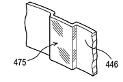
図9の背板446のリブ475もまた、プレス加工によって形成される。
The
The
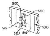
図12の背板546のリブ575は、背板の主本体部から折り曲げた複数のタブ58A、58B、58C、58Dとして形成される。各タブは、ブレーキディスクの回転軸に対してそれぞれ異なる半径距離の所に配置される。
The
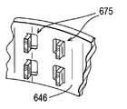
図11の背板646のリブ675もやはり、背板の主本体部から折り曲げた複数のタブによって形成される。しかし、この場合は、タブは対をなして設けられ、各対がディスクの回転軸に対してほぼ同じ半径距離の所に配置される。
The
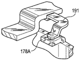
図17〜20は、タブ178に類似するが、凹部190が半剪断加工によって設けられた変形形態178Aを示す。ブレーキパッドばね191は、凹部190にはまり込む凸部192を含み、それによって、ばね191がブレーキパッドに対して適正に配置されることになる。図17〜20に示されるように、ブレーキばねの凸部はブレーキパッドの凹部と係合する。代替実施形態では、ブレーキパッドの凸部がブレーキばねの凹部と係合して、同じ機能を果たす。
FIGS. 17-20 show a
図15及び16は、本発明による摺動キャリパ712の代替実施形態を示す。これらの図では、キャリパ112の径方向負荷当接パッド156及び158が削除され、1対の突起部781(そのうちの1つだけを示す)で置き換えられており、その径方向外側に面する表面782が径方向負荷当接部として働くことを除いて、摺動キャリパ112と同じである。したがって、車体外側パッド背板746には、タブ178、179又は278と同等の折り曲げたタブは必要でない。突起部781は、摺動キャリパ本体と一体に鋳造される。あるいは、別個の当接部881を設けて(図13参照)、ボルト883で摺動キャリパ812に固定することもできる。あるいは、ピン981を摺動キャリパ912の孔に固定することもできる(図14参照)。
15 and 16 show an alternative embodiment of a sliding
上述のように、従来技術の作動装置側ブレーキパッド30と反作用側ブレーキパッド32は、同一である。同様に、ブレーキパッド130と132は同一である。車体内側と車体外側で同一のブレーキパッドを有するブレーキ組立体を設計することによって、部品の種類が減少するだけでなく、パッドがブレーキ組立体に誤ってはめ込まれる可能性も低減する。同一のブレーキパッドは、本質的に互いに交換可能である。あまり好ましくはないものの、同一ではないが、それでもやはり互いに交換可能なブレーキパッドを使用することも可能である。
As described above, the actuator
「互いに交換可能」という用語は、本発明に従って2つのブレーキパッドをブレーキ組立体にはめ込む際に用いるとき、2つの互いに交換可能なブレーキパッドのうちの第1のパッドを、車体内側又は車体外側にはめ込むとともに2つの互いに交換可能なブレーキパッドのうちの第2のパッドを車体内側及び車体外側のうち他方の側にはめ込むことができ、作動装置の動作によって、それら2つの互いに交換可能なブレーキパッドがはめ込まれたどちらの側にもブレーキがかけられるという意味であることを理解されたい。 The term “interchangeable” means that when the two brake pads are used in the brake assembly according to the present invention, the first of the two interchangeable brake pads is placed inside or outside the vehicle body. The second pad of the two interchangeable brake pads can be fitted to the other side of the vehicle body inner side and the vehicle body outer side. It should be understood that this means that the brake can be applied to either side that is fitted.
したがって、ブレーキ組立体のいくつかの設計は、同一でないとはいえ、本発明とは無関係な軽微な点でしか異ならないブレーキパッドを有する。すなわち、ブレーキパッドのいくつかは、車体内側ブレーキパッドの摩擦材料に電気磨耗指示計が埋め込まれるが、車体外側パッドにはそのような磨耗指示計を含まない。代替の設計では、車体内側ブレーキパッドの摩擦材料に、磨耗指示器を収容するための孔を予め穿設することもでき、車体外側ブレーキパッドはそのような孔を設けない。あるいは、車体内側ブレーキパッドに、磨耗指示計の固定に関連する突起部もしくは凹部、又はそのような磨耗指示計に至る電気リード線を設けることもでき、車体外側ブレーキパッドには同様の機構は設けない。2つのブレーキパッドで摩擦材料の厚さが異なってもよく、又はブレーキパッド背板の厚さが異なってもよい。そのようなパッドは、同一ではないものの、本発明ではそれでもやはり互いに交換可能とすることができる。 Thus, some designs of brake assemblies have brake pads that are different but differ only in minor aspects that are not relevant to the present invention. That is, some of the brake pads have an electrical wear indicator embedded in the friction material of the vehicle body inner brake pad, while the vehicle body outer pad does not include such a wear indicator. In an alternative design, the friction material of the vehicle body inner brake pad can be pre-drilled with a hole for receiving the wear indicator, and the vehicle outer brake pad does not provide such a hole. Alternatively, the vehicle body inner brake pad may be provided with a protrusion or recess related to the fixing of the wear indicator, or an electrical lead leading to such a wear indicator, and a similar mechanism is provided on the vehicle outer brake pad. Absent. The two brake pads may have different friction material thicknesses, or the brake pad backplates may have different thicknesses. Such pads are not identical, but can still be interchangeable in the present invention.
後で分かるように、いくつかの従来技術の設計では、1つ又は複数のピストンが車体内側ブレーキパッドの背面に局所的に締付け力を加えることにより、締付け負荷が車体内側ブレーキパッドに加えられる。車体外側ブレーキパッドの背面に加えられる締付け負荷は、一般に(generally)とても局所的なものではない。このため、車体内側ブレーキパッドに負荷分散機構を設けるが、車体外側ブレーキパッドにはそのような機構が必要でないことが知られている。特に、車体内側ブレーキパッドは、車体外側ブレーキパッドに比べてより厚い背板を備えることがある。あるいは、作動装置ピストンと作動装置側ブレーキパッドとの間に別個の負荷分散板を挿入することもでき、キャリパの反作用側にはそのような分散板は必要でない。そのような分散板を本発明とともに用いる場合、分散板は、車体内側ブレーキパッド背板の凸部を受ける凹部を含むことができる。 As will be seen later, in some prior art designs, one or more pistons apply a clamping force locally on the back of the vehicle body inner brake pad, thereby applying a tightening load to the vehicle inner brake pad. The tightening load applied to the backside of the vehicle body outer brake pad is generally not very local. For this reason, a load distribution mechanism is provided on the vehicle body inner brake pad, but it is known that such a mechanism is not necessary for the vehicle body outer brake pad. In particular, the vehicle body inner brake pad may include a thicker back plate than the vehicle body outer brake pad. Alternatively, a separate load distribution plate can be inserted between the actuator piston and the actuator side brake pad, and no such distribution plate is required on the reaction side of the caliper. When such a dispersion plate is used with the present invention, the dispersion plate can include a recess for receiving the protrusion of the vehicle body inner brake pad back plate.
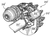
図22〜26は、ブレーキ組立体310’の他の実施形態を示す。これらの図では、ブレーキ組立体110と同じ構成部品には200’を加えた番号が付されている。
この場合は、径方向負荷当接パッド356’及び358’が、ブレーキパッド背板の下側縁部393’の径方向車体内側に設けられる。
22-26 show another embodiment of the brake assembly 310 '. In these drawings, the same components as the
In this case, radial
上述のように、欧州特許第0752541号は、ブレーキパッドがうっかり逆さまにはめ込まれることのないシステムを提供する。本発明もまた、ブレーキパッドが逆さまにはめ込まれないように保証する以下のような方策を提供する。 As mentioned above, EP 0752541 provides a system in which the brake pads are not inadvertently fitted upside down. The present invention also provides the following measures to ensure that the brake pads are not set upside down.
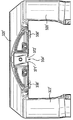
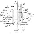
図27は、ブレーキ組立体310’の(図24と同じ方向から見た)概略平面図を示す。ピストン360’が完全に引っ込んだ位置で示され、すなわち、ブレーキパッドが磨耗するにつれてそれらパッドの通常の作動位置を調整するためのピストン360’に連結された調整機構397’を巻き戻すか又は調整解除することにより、ピストンと締付け負荷当接部344’との間隔Dを最大にしてある。ブレーキパッド330’及び332’は、新しいブレーキパッド、すなわち磨耗していないブレーキパッドである。ブレーキパッドはそれぞれスラスト面394’を有し、その面は、車体内側ブレーキパッド330’に関しては、ピストン360’の頭部(締付け負荷当接部)によって係合され、車体外側ブレーキパッド332’に関しては、締付け負荷当接部344’によって係合される。各ブレーキパッドはまた、摩擦材料製の摩擦面395’を有する。各ブレーキパッドは、スラスト面394’と摩擦面395’との間隔d1を有する。各ブレーキパッドはまた、摩擦面395’とそれとは反対側に面する径方向に向いたリム375’の間で画定される最大厚d2を有する。したがって、リブ375’の厚さd3は、間隔d2から間隔d1を差し引いた間隔に等しい。ディスク324’の厚さはd4である。
FIG. 27 shows a schematic plan view (seen from the same direction as FIG. 24) of the brake assembly 310 '. The piston 360 'is shown in a fully retracted position, i.e., rewinding or adjusting an adjustment mechanism 397' connected to the piston 360 'to adjust the normal operating position of the pads as the brake pads wear. By releasing, the distance D between the piston and the tightening load contact portion 344 'is maximized. Brake pads 330 'and 332' are new brake pads, i.e. brake pads that are not worn. Each brake pad has a thrust surface 394 ', which is engaged by the head of the piston 360' (clamping load abutment) with respect to the vehicle body inner brake pad 330 'and with respect to the vehicle body outer brake pad 332'. Are engaged by the tightening
ブレーキ組立体310’の設計は、Dがd1とd2とd4とを足し合わせた値よりも小さくなっており、したがって、ブレーキパッドの一方又は両方を誤って逆さまにはめ込む、すなわち、背板をディスクに面してはめ込んだ状態ではキャリパを完全に組み立てることは不可能であることが理解されよう。これは、ブレーキパッドの1つを逆さまに取り付けるには、d1とd2とd4とを足し合わせた空間が必要となるからである。したがって、突出したリブ375’を背板に設けることで、パッドが逆さまにはめ込まれた場合には、リブ厚(d3)が実質的に、ブレーキパッドの実際の厚さを増すことになる。というのは、パッドが正しくはめ込まれた場合、リブ厚は径方向に向いた溝354’又は2つのピストン360’の間に収容されるが、パッドが逆さまにはめ込まれた場合には、リブがディスクの平坦面に当接することになるからである。 The design of the brake assembly 310 'is such that D is less than the sum of d1, d2 and d4, so one or both of the brake pads are accidentally fitted upside down, ie the back plate is disc It will be understood that it is not possible to completely assemble the caliper when in the face-in position. This is because, in order to attach one of the brake pads upside down, a space in which d1, d2, and d4 are added is required. Accordingly, by providing the protruding rib 375 'on the back plate, the rib thickness (d3) substantially increases the actual thickness of the brake pad when the pad is fitted upside down. This is because if the pad is properly seated, the rib thickness will be accommodated between the radially oriented grooves 354 'or the two pistons 360', but if the pad is seated upside down, the rib will This is because it comes into contact with the flat surface of the disk.
本発明を摺動キャリパブレーキに関して説明してきた。本発明は、摺動ディスクを有する固定キャリパブレーキにも等しく適用可能である。そのような構成を図28に示す。この図では、キャリパ112”は、キャリパ112”と同様であるが、この場合はキャリパ112”が軸170”に固定されているので軸方向に移動できない点だけが異なる。この場合は、ディスク124”はハブ113”のキー溝に摺動可能に取り付けられる。この場合は、作動装置が作動すると、車体内側ブレーキパッド(図示せず)がブレーキディスク124”の方に移動し、次いで、ブレーキディスクがそのスプライン(図示せず)に沿って摺動し、車体外側ブレーキパッド(図示せず)の方に移動する。
The present invention has been described with respect to a sliding caliper brake. The present invention is equally applicable to fixed caliper brakes having a sliding disk. Such a configuration is shown in FIG. In this figure, the
ブレーキ組立体110、310’、及び110”はすべて、片側から作動されるブレーキ組立体であることを理解されたい。これらのブレーキ組立体に連結される作動装置は、どの場合もブレーキディスクの車体内側にある。
It should be understood that the
作動装置ピストン160の動作は周知である。作動装置ピストンのある特定の実施形態の完全な説明としては、米国特許第6435319号を参照されたい。作動装置が動作すると、作動装置ピストン160が周方向に離れた2つの位置で、連結されたブレーキパッド背板に軸方向の負荷を加えることが理解されよう。これによって、径方向に向いたリブ175を収容する空間ができる。本発明は、軸方向の力が、周方向に間隔を置いて位置する2つの当接部を介して加えられ、それによって、径方向に向いたリブ又は他の凸部を据えることができる空間が設けられるどんな作動装置機構にも等しく適用可能である。
The operation of the
10 ブレーキ組立体 12 摺動キャリパ
14 キャリア 16 空気室
18 作動装置ハウジング 20、22 架橋腕部
24 ブレーキディスク 26 反作用側部分
28 窓
30 作動装置側(車体内側)ブレーキパッド
32 反作用側(車体外側)ブレーキパッド
34、36 キャリア腕部 38 キャリア反作用側部分
40、41 トルク反作用当接部 42、43 径方向負荷当接部
44 締付け負荷当接部 46 背板
48 摩擦材料 50 パッド保持器
54 パッドばね 110 ブレーキ組立体
112 摺動キャリパ 114 キャリア
118 作動装置ハウジング 120、122 架橋腕部
128 窓 130 車体内側ブレーキパッド
132 車体外側ブレーキパッド 144 締付け負荷当接部
146 背板 150 パッド保持器
152 ボルト 154 溝
156、158 径方向負荷当接パッド 160 ピストン(タペット組立体)
161、162 孔 163、164 ピン
165 凹部
166、167、171、172 トルク反作用当接部
168、169 径方向負荷当接部 170 車軸
173、174 周方向端部 175 リブ
176、177 縁部 178、179 タブ
178A タブ変形形態 190 凹部
191 ばね 192 凸部
246 背板 275 リブ
278 タブ 346 背板
375 半剪断リブ 446 背板
475 リブ 546 背板
575 リブ 58A、58B、58C、58D タブ
646 背板 675 リブ
712 摺動キャリパ 746 背板
781 突起部 782 表面
812 摺動キャリパ 881 当接部
883 ボルト 912 摺動キャリパ
981 ピン 210’ ブレーキ組立体
211’ 車両車軸 213’ 回転ハブ
214’ キャリア 215’ ボルト
310’ ブレーキ組立体 324’ ブレーキディスク
330’ 車体内側ブレーキパッド 332’ 車体外側ブレーキパッド
344’ 締付け負荷当接部 354’ 溝
356’、358’ 径方向負荷当接パッド
360’ ピストン 375’ リブ
393’ 縁部 394’ スラスト面
395’ 摩擦面 397’ 調整機構
110” ブレーキ組立体 112” キャリパ
113” ハブ 124” ブレーキディスク
170” 軸
DESCRIPTION OF
30 Actuator side (vehicle body inside)
161, 162
Claims (20)
互いに交換可能であり、それぞれが第1及び第2の周方向端部を有し、それぞれが前記第1及び第2の周方向端部から離れた第1の構成体を有する、第1及び第2のブレーキパッドとを含み、
前記第1のブレーキパッドは、前記第1のブレーキパッドから前記第1の側部分に制動トルク負荷を伝達するために、前記第1のブレーキパッドの前記第1の構成体が前記第1の側部分の第2の構成体と係合して、前記第1の側部分にはめ込まれ、
前記第2のブレーキパッドは、前記第2のブレーキパッドから前記ブレーキ組立体に制動トルク負荷を伝達するために、前記第2のブレーキパッドの前記第1及び第2の周方向端部が前記ブレーキ組立体のそれぞれの第1及び第2の周方向に間隔を置いて配置された当接部と係合して、前記第2の側部分にはめ込まれた、ブレーキ組立体。 A caliper in which the first side portion is connected to the second side portion by two bridging arms spaced apart in the circumferential direction;
First and second, interchangeable with each other, each having first and second circumferential ends, each having a first structure spaced from said first and second circumferential ends 2 brake pads,
The first brake pad transmits the braking torque load from the first brake pad to the first side portion so that the first structure of the first brake pad is the first side. Engaged with the second component of the part and fitted into the first side part;
The second brake pad is configured such that the first and second circumferential ends of the second brake pad are connected to the brake in order to transmit a braking torque load from the second brake pad to the brake assembly. A brake assembly engaged with said second side portion by engaging respective first and second circumferentially spaced abutments of the assembly.
前記ブレーキ組立体が、前記第1及び第2のブレーキパッドの1つを前記キャリパに組み込んだ状態で、前記第1及び第2のブレーキパッドの他方を、前記1及び第2のブレーキパッドの前記他方の前記ブレーキパッド背板が前記ディスクに面するようには組み込むことができないように構成される、請求項1から16のいずれかに記載のブレーキ組立体。 A brake disc disposed between the first brake pad and the second brake pad, the first brake pad having a first friction material attached to one side thereof and the other side The one of the first components is attached, the first friction material has a first brake pad backplate facing the disc, and the second brake pad is on one side thereof A second friction material is attached and the one of the first constructions is attached to the other side, the second friction material having a second brake pad backplate facing the disc;
With the brake assembly incorporating one of the first and second brake pads into the caliper, the other of the first and second brake pads is connected to the one of the first and second brake pads. The brake assembly according to any one of claims 1 to 16, wherein the other brake pad back plate is configured not to be assembled so as to face the disc.
凸部として設けられた前記第1の構成体が凸部厚(d3)を有し、
前記ブレーキディスクがディスク厚(d4)を有し、
前記ブレーキ組立体が、前記摩擦材料が磨耗するにつれて前記ブレーキパッドの移動位置を調整するように調整可能な調整機構を含み、
前記調整機構が、前記第2のブレーキパッドの前記スラスト面と係合する締付け負荷当接部を備え、前記第1の部分が、前記第2のブレーキパッドの前記スラスト面と係合する締付け負荷当接部を備え、
前記調整機構の前記締付け負荷当接部と前記第1の部分の前記締付け負荷当接部とである間隔が画定され、前記間隔が調整可能であり、最大間隔(D)及び最小間隔を有し、
前記第1のブレーキパッドの前記パッド厚(d1)と、前記第2のブレーキパッドの前記パッド厚(d1)と、前記凸部厚(d3)と、前記ディスク厚(d4)とを足し合わせた間隔が、最大間隔(D)よりも大きい、請求項17に記載のブレーキ組立体。 The brake pad backplate comprises a thrust surface on the other side and a friction surface of the friction material, thereby defining a pad thickness (d1) between the thrust surface and the friction surface;
The first structure provided as a convex portion has a convex thickness (d3),
The brake disc has a disc thickness (d4);
The brake assembly includes an adjustment mechanism adjustable to adjust the travel position of the brake pad as the friction material wears;
The adjustment mechanism includes a tightening load contact portion that engages with the thrust surface of the second brake pad, and the first portion engages with the thrust surface of the second brake pad. A contact portion,
An interval between the tightening load contact portion of the adjustment mechanism and the tightening load contact portion of the first portion is defined, the interval is adjustable, and has a maximum interval (D) and a minimum interval. ,
The pad thickness (d1) of the first brake pad, the pad thickness (d1) of the second brake pad, the protrusion thickness (d3), and the disc thickness (d4) are added together. The brake assembly according to claim 17, wherein the spacing is greater than the maximum spacing (D).
前記第1及び第2のブレーキパッドが、一方の側に取り付けられた摩擦材料と、他方の側に取り付けられた締付け負荷当接部とを備え、前記摩擦材料が摩擦表面を有し、それによって前記締付け負荷当接部と前記摩擦表面との間でパッド厚(d1)を画定する、請求項1に記載のブレーキ組立体を提供するステップと、
前記第1の構成体を厚さ(d3)を有する凸部として提供するステップと、
ブレーキディスク厚(d4)を有するブレーキディスクを提供するステップと、
前記摩擦材料が磨耗するにつれて前記ブレーキパッドの作動位置を調整するように調整可能な調整機構を提供するステップと、
前記調整機構を完全に調整解除して、幅(D)の空間を提供するステップであって、
前記第1のブレーキパッドの前記パッド厚(d1)と、前記第2のブレーキパッドの前記パッド厚(d1)と、前記凸部厚(d3)と、前記ブレーキディスク厚(d4)とを足し合わせた間隔が、幅(D)よりも大きくなるステップと、
前記第1及び第2のブレーキパッドと前記ブレーキディスクとを前記空間に組み込むステップとを含む、ブレーキ組立体を組み立てる方法。 A method of assembling a brake assembly,
The first and second brake pads comprise a friction material attached to one side and a tightening load abutment attached to the other side, the friction material having a friction surface, thereby Providing a brake assembly (d1) between the tightening load abutment and the friction surface;
Providing the first structure as a protrusion having a thickness (d3);
Providing a brake disc having a brake disc thickness (d4);
Providing an adjustment mechanism adjustable to adjust the operating position of the brake pad as the friction material wears;
Fully detuning the adjustment mechanism to provide a space of width (D),
The pad thickness (d1) of the first brake pad, the pad thickness (d1) of the second brake pad, the protrusion thickness (d3), and the brake disc thickness (d4) are added together. A step in which the interval is greater than the width (D);
Incorporating the first and second brake pads and the brake disc into the space.
Applications Claiming Priority (1)
| Application Number | Priority Date | Filing Date | Title |
|---|---|---|---|
| GBGB0414108.1A GB0414108D0 (en) | 2004-06-24 | 2004-06-24 | A brake assembly |
Publications (2)
| Publication Number | Publication Date |
|---|---|
| JP2006010079A true JP2006010079A (en) | 2006-01-12 |
| JP2006010079A5 JP2006010079A5 (en) | 2008-05-29 |
Family
ID=32800067
Family Applications (1)
| Application Number | Title | Priority Date | Filing Date |
|---|---|---|---|
| JP2005183202A Ceased JP2006010079A (en) | 2004-06-24 | 2005-06-23 | Brake assembly |
Country Status (9)
| Country | Link |
|---|---|
| US (1) | US7631733B2 (en) |
| EP (1) | EP1610025B1 (en) |
| JP (1) | JP2006010079A (en) |
| CN (1) | CN1712750A (en) |
| AT (1) | ATE453813T1 (en) |
| BR (1) | BRPI0503772A (en) |
| DE (1) | DE602005018572D1 (en) |
| GB (1) | GB0414108D0 (en) |
| PL (1) | PL1610025T3 (en) |
Families Citing this family (33)
| Publication number | Priority date | Publication date | Assignee | Title |
|---|---|---|---|---|
| DE102004050349B4 (en) * | 2004-10-15 | 2007-06-14 | Wabco Radbremsen Gmbh | Commercial vehicle disc brake |
| DE102004052541C5 (en) | 2004-10-28 | 2021-07-29 | Bpw Bergische Achsen Kg | Brake caliper for a disc brake |
| GB0521326D0 (en) * | 2005-10-20 | 2005-11-30 | Bentley Motors Ltd | A pad retention device |
| DE102005050581B3 (en) * | 2005-10-21 | 2007-06-06 | Knorr-Bremse Systeme für Nutzfahrzeuge GmbH | Disc brake, in particular for a commercial vehicle |
| EP1898115B1 (en) * | 2006-09-02 | 2008-11-26 | BPW Bergische Achsen KG | Vehicle disc brake |
| DE102007019429B4 (en) * | 2007-04-25 | 2009-01-02 | Knorr-Bremse Systeme für Nutzfahrzeuge GmbH | Disc brake, in particular for a commercial vehicle |
| DE102007035162B3 (en) * | 2007-07-25 | 2009-04-09 | Knorr-Bremse Systeme für Nutzfahrzeuge GmbH | Disc brake, in particular for a commercial vehicle |
| US20090101456A1 (en) * | 2007-10-18 | 2009-04-23 | Akebono Corporation (North America) | Disk thickness variation tolerant brake system and method for manufacturing thereof |
| JP4818250B2 (en) * | 2007-12-27 | 2011-11-16 | 日立オートモティブシステムズ株式会社 | Disc brake |
| US8505699B2 (en) * | 2008-02-06 | 2013-08-13 | Material Sciences Corporation | Flanged shim for disc brake squeal attenuation |
| US9046143B2 (en) * | 2008-06-25 | 2015-06-02 | Michael T. Barland | Caliper cover |
| DE102010034728A1 (en) | 2010-08-18 | 2012-02-23 | Knorr-Bremse Systeme für Nutzfahrzeuge GmbH | Disc brake, in particular for a commercial vehicle |
| US8485323B2 (en) * | 2010-10-08 | 2013-07-16 | Akebono Brake Corporation | Caliper assembly for disc brake system |
| USD641670S1 (en) * | 2010-11-24 | 2011-07-19 | Hb Performance Systems, Inc. | Brake pad |
| DE102012008003A1 (en) | 2012-04-20 | 2013-10-24 | Knorr-Bremse Systeme für Nutzfahrzeuge GmbH | Disc brake for vehicles |
| BR112015011677B1 (en) * | 2012-11-27 | 2022-05-24 | Hendrickson Usa, L.L.C | Axle assembly for a braking system component of an axle and suspension system |
| DE102013016312A1 (en) | 2013-10-04 | 2015-04-09 | Knorr-Bremse Systeme für Nutzfahrzeuge GmbH | disc brake |
| DE102014107401A1 (en) * | 2014-05-26 | 2015-11-26 | Knorr-Bremse Systeme für Nutzfahrzeuge GmbH | Disc brake, caliper and brake pad set for a disc brake |
| EP3023666B2 (en) * | 2014-11-20 | 2022-09-14 | Meritor Heavy Vehicle Braking Systems (UK) Limited | Disc brake assembly |
| TWD172383S (en) * | 2015-03-17 | 2015-12-11 | 溫芫鋐 | Part of the heat dissipation structure of the cooling pad |
| DE102015122569A1 (en) * | 2015-12-22 | 2017-06-22 | Bpw Bergische Achsen Kg | Disc brake, brake pad for a disc brake, hold-down for attaching brake pads |
| CN109328273B (en) * | 2016-05-20 | 2020-07-17 | 克诺尔商用车制动系统有限公司 | Disk brake, brake lining and brake lining set for a commercial vehicle |
| DE102017105641B4 (en) | 2017-03-16 | 2022-09-15 | Knorr-Bremse Systeme für Nutzfahrzeuge GmbH | Brake carrier and disc brake |
| US10066687B2 (en) * | 2016-10-04 | 2018-09-04 | Michael Barland | Caliper cover |
| EP3450791A1 (en) * | 2017-08-31 | 2019-03-06 | Meritor Heavy Vehicle Braking Systems (UK) Limited | A friction element |
| EP3492767B1 (en) * | 2017-11-29 | 2020-11-18 | Meritor Heavy Vehicle Braking Systems (UK) Limited | A disc brake |
| EP3499073A1 (en) * | 2017-12-15 | 2019-06-19 | Meritor Heavy Vehicle Braking Systems (UK) Limited | Brake caliper |
| US20190271367A1 (en) * | 2018-03-02 | 2019-09-05 | Arvinmeritor Technology, Llc | Brake assembly having a bridge |
| EP3584462B1 (en) | 2018-06-20 | 2020-05-20 | WABCO Europe BVBA | Brake lining device for a disc brake |
| EP3779222B1 (en) | 2019-08-13 | 2024-04-03 | Meritor Heavy Vehicle Braking Systems (UK) Limited | A disc brake |
| EP3835612B1 (en) * | 2019-12-10 | 2022-08-24 | ZF CV Systems Europe BV | Disc brake, especially for commercial vehicles and vehicle comprising a disc brake, especially a commercial vehicle comprising a disc brake |
| CN110821985A (en) * | 2019-12-11 | 2020-02-21 | 隆中控股集团股份有限公司 | Brake and brake block assembly |
| DE102022206469A1 (en) | 2022-06-27 | 2023-12-28 | Hl Mando Corporation | MULTI-PIECE BRAKE CALIPER WITH AT LEAST ONE HOLLOW SECTION |
Citations (7)
| Publication number | Priority date | Publication date | Assignee | Title |
|---|---|---|---|---|
| JPS59133836A (en) * | 1982-12-24 | 1984-08-01 | ル−カス・インダストリ−ズ・パブリツク・リミテツド・カンパニ− | Sliding caliper disk brake |
| JPH02286927A (en) * | 1989-04-25 | 1990-11-27 | General Motors Fr | Disc brake caliper assembly |
| JPH05196067A (en) * | 1991-08-08 | 1993-08-06 | Alfred Teves Gmbh | Floating frame spot type disc brake for high-output car |
| JPH06280905A (en) * | 1993-03-29 | 1994-10-07 | Nissin Kogyo Kk | Disc brake |
| JPH08159188A (en) * | 1994-12-12 | 1996-06-18 | Hosei Brake Kogyo Kk | Disc brake |
| JPH10299802A (en) * | 1997-04-22 | 1998-11-13 | Hitachi Chem Co Ltd | Disk brake pad and manufacture thereof |
| JP2004506153A (en) * | 2000-08-07 | 2004-02-26 | フレニ・ブレンボ エス・ピー・エー | Brake pads for disc brakes |
Family Cites Families (21)
| Publication number | Priority date | Publication date | Assignee | Title |
|---|---|---|---|---|
| US3042152A (en) * | 1957-04-01 | 1962-07-03 | Dunlop Rubber Co | Fluid actuated disc brakes and housings and friction elements therefor |
| GB880870A (en) | 1957-04-01 | 1961-10-25 | Dunlop Rubber Co | Improvements in disc brakes |
| US3390744A (en) * | 1966-10-19 | 1968-07-02 | Hotel Statler Hilton | Self-energizing disc brake |
| US4130186A (en) * | 1975-05-20 | 1978-12-19 | Societe Anonyme Francaise Du Ferodo | Ribbed brake shoe support plate for cylindrical ring type brake |
| GB1538865A (en) * | 1975-12-11 | 1979-01-24 | Automotive Prod Co Ltd | Disc brake assembly |
| GB1538864A (en) | 1975-12-11 | 1979-01-24 | Automotive Prod Co Ltd | Disc brake assembly |
| JPS5736835Y2 (en) * | 1976-06-23 | 1982-08-13 | ||
| US4200173A (en) | 1978-08-01 | 1980-04-29 | Kelsey-Hayes Company | Sliding caliper disc brake |
| FR2515760A1 (en) * | 1981-10-30 | 1983-05-06 | Valeo | PERFECTED BRAKE PAD |
| US4823920A (en) * | 1988-05-02 | 1989-04-25 | Kelsey-Hayes Company | Sliding caliper disc brake and brake shoe assembly therefor |
| US4995482A (en) * | 1988-06-14 | 1991-02-26 | Tokico Ltd. | Disc brake |
| JPH0736191Y2 (en) * | 1989-12-20 | 1995-08-16 | トキコ株式会社 | Disc brake pad |
| DE4126339C2 (en) | 1991-08-09 | 2002-04-04 | Continental Teves Ag & Co Ohg | Part floating disc brake for high-performance vehicles |
| GB9513709D0 (en) | 1995-07-05 | 1995-09-06 | Lucas Ind Plc | Disc brake |
| JP3689825B2 (en) | 1996-05-11 | 2005-08-31 | 株式会社日立製作所 | Disc brake |
| FR2751391B1 (en) * | 1996-07-22 | 1998-10-09 | Alliedsignal Materiaux De Fric | DEVICE FORMING A SUPPORT PLATE FOR AT LEAST ONE BRAKE LINING PLATE FOR A VEHICLE DISC BRAKE |
| DE19743538A1 (en) | 1997-10-01 | 1999-04-08 | Wabco Perrot Bremsen Gmbh | Sliding caliper disc brake |
| GB9806542D0 (en) | 1998-03-26 | 1998-05-27 | Lucas Ind Plc | Disc brake actuator |
| DE19931024C1 (en) * | 1999-07-06 | 2001-04-19 | Lucas Ind Plc | Disc brake and brake pad for it |
| EP1085229A1 (en) * | 1999-09-17 | 2001-03-21 | Brembo Engineering S.p.A. | Disc brake |
| US6932197B2 (en) * | 2002-03-29 | 2005-08-23 | Sram Corporation | Gimbaled pad support |
-
2004
- 2004-06-24 GB GBGB0414108.1A patent/GB0414108D0/en not_active Ceased
-
2005
- 2005-06-20 EP EP05253796A patent/EP1610025B1/en not_active Not-in-force
- 2005-06-20 AT AT05253796T patent/ATE453813T1/en not_active IP Right Cessation
- 2005-06-20 PL PL05253796T patent/PL1610025T3/en unknown
- 2005-06-20 DE DE602005018572T patent/DE602005018572D1/en active Active
- 2005-06-23 JP JP2005183202A patent/JP2006010079A/en not_active Ceased
- 2005-06-23 US US11/159,831 patent/US7631733B2/en not_active Expired - Fee Related
- 2005-06-24 BR BR0503772-7A patent/BRPI0503772A/en active Search and Examination
- 2005-06-24 CN CNA2005100823599A patent/CN1712750A/en active Pending
Patent Citations (7)
| Publication number | Priority date | Publication date | Assignee | Title |
|---|---|---|---|---|
| JPS59133836A (en) * | 1982-12-24 | 1984-08-01 | ル−カス・インダストリ−ズ・パブリツク・リミテツド・カンパニ− | Sliding caliper disk brake |
| JPH02286927A (en) * | 1989-04-25 | 1990-11-27 | General Motors Fr | Disc brake caliper assembly |
| JPH05196067A (en) * | 1991-08-08 | 1993-08-06 | Alfred Teves Gmbh | Floating frame spot type disc brake for high-output car |
| JPH06280905A (en) * | 1993-03-29 | 1994-10-07 | Nissin Kogyo Kk | Disc brake |
| JPH08159188A (en) * | 1994-12-12 | 1996-06-18 | Hosei Brake Kogyo Kk | Disc brake |
| JPH10299802A (en) * | 1997-04-22 | 1998-11-13 | Hitachi Chem Co Ltd | Disk brake pad and manufacture thereof |
| JP2004506153A (en) * | 2000-08-07 | 2004-02-26 | フレニ・ブレンボ エス・ピー・エー | Brake pads for disc brakes |
Also Published As
| Publication number | Publication date |
|---|---|
| BRPI0503772A (en) | 2006-02-07 |
| US20050284710A1 (en) | 2005-12-29 |
| DE602005018572D1 (en) | 2010-02-11 |
| EP1610025B1 (en) | 2009-12-30 |
| PL1610025T3 (en) | 2010-05-31 |
| US7631733B2 (en) | 2009-12-15 |
| CN1712750A (en) | 2005-12-28 |
| ATE453813T1 (en) | 2010-01-15 |
| EP1610025A1 (en) | 2005-12-28 |
| GB0414108D0 (en) | 2004-07-28 |
Similar Documents
| Publication | Publication Date | Title |
|---|---|---|
| JP2006010079A (en) | Brake assembly | |
| EP2199640B1 (en) | A disc brake | |
| JP4547090B2 (en) | Disc brake system | |
| JP2004132545A (en) | Brake caliper | |
| US10502273B2 (en) | Pneumatically or electromechanically actuated disk brake for utility vehicles | |
| JP5267743B1 (en) | Disc brake device and caliper | |
| US10801569B2 (en) | Disc brake | |
| US11725703B2 (en) | Brake assembly | |
| JP2005106291A (en) | Brake caliper | |
| WO2019049539A1 (en) | Vehicular disc brake | |
| US20180106310A1 (en) | Disc brake device | |
| JP5637318B2 (en) | Disc brake device and caliper | |
| US20190063534A1 (en) | Disc brake | |
| JP2012072842A (en) | Floating type disc brake | |
| JP4718422B2 (en) | Disc brake | |
| EP1408252B1 (en) | Multi-disc brake | |
| EP1647733B1 (en) | Brake pad | |
| EP1350038A1 (en) | Mounting friction elements to disc brakes | |
| JP2008164070A (en) | Opposed-to-piston disc brake device | |
| JP5087645B2 (en) | Disc brake with pin rail caliper | |
| JPH09296836A (en) | Disc brake caliper | |
| JP2023134009A (en) | floating brake disc | |
| KR20230131136A (en) | Disc brake arrangement | |
| GB2361969A (en) | Resilient mounting for an axially moveable brake disc | |
| JP2010007844A (en) | Disc brake |
Legal Events
| Date | Code | Title | Description |
|---|---|---|---|
| A521 | Request for written amendment filed |
Free format text: JAPANESE INTERMEDIATE CODE: A523 Effective date: 20080415 |
|
| A621 | Written request for application examination |
Free format text: JAPANESE INTERMEDIATE CODE: A621 Effective date: 20080415 |
|
| A131 | Notification of reasons for refusal |
Free format text: JAPANESE INTERMEDIATE CODE: A131 Effective date: 20110208 |
|
| A977 | Report on retrieval |
Free format text: JAPANESE INTERMEDIATE CODE: A971007 Effective date: 20110210 |
|
| A521 | Request for written amendment filed |
Free format text: JAPANESE INTERMEDIATE CODE: A523 Effective date: 20110422 |
|
| A601 | Written request for extension of time |
Free format text: JAPANESE INTERMEDIATE CODE: A601 Effective date: 20110422 |
|
| A602 | Written permission of extension of time |
Free format text: JAPANESE INTERMEDIATE CODE: A602 Effective date: 20110502 |
|
| A521 | Request for written amendment filed |
Free format text: JAPANESE INTERMEDIATE CODE: A523 Effective date: 20110517 |
|
| A045 | Written measure of dismissal of application [lapsed due to lack of payment] |
Free format text: JAPANESE INTERMEDIATE CODE: A045 Effective date: 20120420 |