EP2199640B1 - A disc brake - Google Patents
A disc brake Download PDFInfo
- Publication number
- EP2199640B1 EP2199640B1 EP09179350A EP09179350A EP2199640B1 EP 2199640 B1 EP2199640 B1 EP 2199640B1 EP 09179350 A EP09179350 A EP 09179350A EP 09179350 A EP09179350 A EP 09179350A EP 2199640 B1 EP2199640 B1 EP 2199640B1
- Authority
- EP
- European Patent Office
- Prior art keywords
- brake
- pad
- pads
- disc brake
- formation
- Prior art date
- Legal status (The legal status is an assumption and is not a legal conclusion. Google has not performed a legal analysis and makes no representation as to the accuracy of the status listed.)
- Active
Links
- 230000015572 biosynthetic process Effects 0.000 claims description 26
- 238000005755 formation reaction Methods 0.000 claims description 26
- 230000002093 peripheral effect Effects 0.000 claims description 6
- 230000000717 retained effect Effects 0.000 claims 1
- 239000002783 friction material Substances 0.000 description 14
- XEEYBQQBJWHFJM-UHFFFAOYSA-N Iron Chemical compound [Fe] XEEYBQQBJWHFJM-UHFFFAOYSA-N 0.000 description 2
- 229910000831 Steel Inorganic materials 0.000 description 1
- 230000004308 accommodation Effects 0.000 description 1
- 238000005266 casting Methods 0.000 description 1
- 238000005336 cracking Methods 0.000 description 1
- 230000003292 diminished effect Effects 0.000 description 1
- 229910052742 iron Inorganic materials 0.000 description 1
- 238000003754 machining Methods 0.000 description 1
- 239000000463 material Substances 0.000 description 1
- 230000002028 premature Effects 0.000 description 1
- 239000010959 steel Substances 0.000 description 1
Images


Classifications
-
- F—MECHANICAL ENGINEERING; LIGHTING; HEATING; WEAPONS; BLASTING
- F16—ENGINEERING ELEMENTS AND UNITS; GENERAL MEASURES FOR PRODUCING AND MAINTAINING EFFECTIVE FUNCTIONING OF MACHINES OR INSTALLATIONS; THERMAL INSULATION IN GENERAL
- F16D—COUPLINGS FOR TRANSMITTING ROTATION; CLUTCHES; BRAKES
- F16D55/00—Brakes with substantially-radial braking surfaces pressed together in axial direction, e.g. disc brakes
- F16D55/02—Brakes with substantially-radial braking surfaces pressed together in axial direction, e.g. disc brakes with axially-movable discs or pads pressed against axially-located rotating members
- F16D55/22—Brakes with substantially-radial braking surfaces pressed together in axial direction, e.g. disc brakes with axially-movable discs or pads pressed against axially-located rotating members by clamping an axially-located rotating disc between movable braking members, e.g. movable brake discs or brake pads
- F16D55/224—Brakes with substantially-radial braking surfaces pressed together in axial direction, e.g. disc brakes with axially-movable discs or pads pressed against axially-located rotating members by clamping an axially-located rotating disc between movable braking members, e.g. movable brake discs or brake pads with a common actuating member for the braking members
- F16D55/225—Brakes with substantially-radial braking surfaces pressed together in axial direction, e.g. disc brakes with axially-movable discs or pads pressed against axially-located rotating members by clamping an axially-located rotating disc between movable braking members, e.g. movable brake discs or brake pads with a common actuating member for the braking members the braking members being brake pads
- F16D55/226—Brakes with substantially-radial braking surfaces pressed together in axial direction, e.g. disc brakes with axially-movable discs or pads pressed against axially-located rotating members by clamping an axially-located rotating disc between movable braking members, e.g. movable brake discs or brake pads with a common actuating member for the braking members the braking members being brake pads in which the common actuating member is moved axially, e.g. floating caliper disc brakes
- F16D55/2265—Brakes with substantially-radial braking surfaces pressed together in axial direction, e.g. disc brakes with axially-movable discs or pads pressed against axially-located rotating members by clamping an axially-located rotating disc between movable braking members, e.g. movable brake discs or brake pads with a common actuating member for the braking members the braking members being brake pads in which the common actuating member is moved axially, e.g. floating caliper disc brakes the axial movement being guided by one or more pins engaging bores in the brake support or the brake housing
-
- F—MECHANICAL ENGINEERING; LIGHTING; HEATING; WEAPONS; BLASTING
- F16—ENGINEERING ELEMENTS AND UNITS; GENERAL MEASURES FOR PRODUCING AND MAINTAINING EFFECTIVE FUNCTIONING OF MACHINES OR INSTALLATIONS; THERMAL INSULATION IN GENERAL
- F16D—COUPLINGS FOR TRANSMITTING ROTATION; CLUTCHES; BRAKES
- F16D55/00—Brakes with substantially-radial braking surfaces pressed together in axial direction, e.g. disc brakes
- F16D2055/0004—Parts or details of disc brakes
- F16D2055/0016—Brake calipers
-
- F—MECHANICAL ENGINEERING; LIGHTING; HEATING; WEAPONS; BLASTING
- F16—ENGINEERING ELEMENTS AND UNITS; GENERAL MEASURES FOR PRODUCING AND MAINTAINING EFFECTIVE FUNCTIONING OF MACHINES OR INSTALLATIONS; THERMAL INSULATION IN GENERAL
- F16D—COUPLINGS FOR TRANSMITTING ROTATION; CLUTCHES; BRAKES
- F16D65/00—Parts or details
- F16D65/02—Braking members; Mounting thereof
Definitions
- the present invention relates to a disc brake. More particularly, the present invention relates to a disc brake incorporating an arrangement for ensuring that brake pads are always fitted in their correct orientation and correct location.
- the two pads are completely identical and are provided with a formation that has rotational symmetry about an axis extending perpendicular to the rotational axis of the brake disc, so that although the pads cannot be fitted with the backplate facing the disc, the pads are interchangeable in an inboard and outboard sense.
- FIG. 1 An example of such a general arrangement is the type of brake illustrated in Figure 1 (although this brake incorporates further features in accordance with the present invention as discussed below).
- This brake is a sliding caliper air disc brake having a single actuating piston/tappet that applies the inboard brake pad directly.
- the inboard pad requires a relatively thick backplate because the central loading from the piston may otherwise tend to cause the inboard pad to flex during its application.
- the outboard pad is supported across virtually the entire rear face of the backplate, and therefore a thinner backplate may be used to save weight and materials cost. The fitting of these two pads in the incorrect location would, at the very least, be likely to cause uneven wear on the outboard pad when fitted in the inboard location, and therefore require the premature replacement of the pad.
- DE102005001482 discloses a brake caliper for a disc brake for motorcycles and/or bicycles having a housing for the accommodation of two brake linings with brake friction material that are mirror images of one another, the brake linings being configured to clamp a brake disc through the brake friction material on braking.
- the brake linings of DE102005001482 each have an arm that prevents an outboard brake lining fitting into the housing in the inboard brake lining location, and vice versa, with the brake friction material thereof facing toward the brake disc.
- the brake linings are mirror images of one another, there is nothing to prevent an outboard brake lining fitting into the housing in the inboard brake lining location, and vice versa, with the brake friction material thereof facing away from the brake disc.
- the brake linings of DE102005001482 could thus be incorrectly fitted.
- EP1998066 shows a hydraulic caliper brake having a housing formed from two halves which accommodates stator plates having friction material intended to engage a brake rotor on braking.
- the stator plates are identical and thus interchangeable.
- US4537292 shows a disc brake with a pair of friction pads configured to engage a brake disc on braking, with at least one of the friction pads mounted on a support member.
- the inboard and outboard pads are substantially mirror images of one another, with one pad having a extension not seen in the other pad. However, this extension does not prevent the pads being interchangeable.
- DE19520050 discloses a disc brake having a calliper and a pair of interchangeable pads having back plates, the pads being supported by the caliper.
- W0200/122100 discloses a disc brake having a brake caliper and interchangeable brake linings mounted therein.
- a first aspect of the present invention provides disc brake comprising:
- a second aspect of the present invention provides first and second disc brake pads for fitment in first and second mounting structures of a disc brake inboard and outboard of a brake rotor, the first pad having a different functional requirement to the second pad such that fitment of the first pad in the second structure and/or the second pad in the first structure would impair the safety, functionality and/or durability of the brake, and wherein to prevent or inhibit such incorrect fitting, the first pad comprises on a peripheral face or a rear face thereof a first formation and the second pad comprises on a peripheral face or a rear face thereof a second formation, the first and second formations being arranged such that the first and second pads have neither mirror symmetry nor rotational symmetry when assembled in the brake and cannot be fitted in an incorrect location or incorrect orientation when the brake has corresponding features within the mounting structures thereof, the first and second disc brake pads preferably further comprising substantially identical structures for the attachment of pad springs.
- a plan view of a brake is indicated generally at 10 according to one embodiment of the present invention is shown.
- the brake comprises a caliper 12 formed from a housing portion 14 and a bridge portion 16 with a radial aperture 17.
- the housing 14 is located inboard and the bridge 16 outboard with respect to that vehicle.
- the caliper 12 is slidably mounted for movement in an inboard/outboard direction with respect to a carrier 18.
- the carrier 18 is mounted to a fixed location with respect to a vehicle axle or steering knuckle (not shown) and is arranged to receive a brake disc or rotor (not shown) in the space indicated at 19.
- an inboard brake pad 20 is located within a first pad mounting structure in the form of an inboard opening 22 of the carrier 18 that is arranged to support the pad in a radially inward and circumferential (i.e. rotational) direction.
- an outboard brake pad 24 is located within a second pad mounting structure in the form of an outboard opening 26 and is supported therein in a similar manner to the inboard brake pad 20.
- the pads 20, 24 may be fitted in the openings 22 and 26 via the radial aperture 17.
- the inboard brake pad 20 comprises a backplate 28 and friction material 30 secured to the backplate.
- the backplate 28 has the function of imparting strength to the brake pad 20, since the friction material 30 itself is relatively brittle.
- the inboard backplate 28 is relatively thick and is manufactured in this embodiment in a casting process from iron or steel to support the friction material 30. Further details of the inboard backplate 28 are discussed in more detail below.
- the outboard brake pad 24 also comprises a backplate 32 and friction material 34.
- the brake has a single piston 36 that engages a rear face of the inboard pad 20, and is actuated via an air chamber (not shown) and operating shaft 38 in a known manner as discussed in further detail in EP 1 852 627 to the present applicant.
- the form of the inboard backplate 28 is different from the outboard backplate 32.
- the inboard backplate 28 is substantially thicker than the outboard backplate 32 (in this embodiment 15mm thick) by virtue of having stiffening elements 40 and a central circular depression 42 to receive the head of the piston 36 formed therein.
- Such an arrangement is desirable for the inboard pad 20 in order that it is able to receive the central loading from the piston 36 during braking without appreciable flexing of the pad occurring.
- the arrangement of the backplate may be altered according to the particular requirements of the brake.
- the outboard pad backplate 32 is a substantially planar cast component (without stiffening ribs) that is significantly thinner (approximately half as thin at 8mm) as the inboard backplate 28. It is possible to use a thinner backplate 28 for the outboard pad 24 because the backplate is supported across substantially all of its rear face by a corresponding support surface 44 of the caliper.
- the general shape and dimensions of their peripheries, as well as formations 46 provided for the attachment of a pad spring 48 are functionally the same. Specifically, their circumferential width and radial height are substantially the same. In addition, the thickness and dimensions of the friction material 30 and 34 on the two pads is identical.
- the outboard pad 24 is fitted in the inboard opening 22, and for the inboard pad 20 to be fitted in the outboard opening 26 in addition to the possibility of the pads being fitted with the friction material 30 and 34 in the wrong direction.
- the fitting of the outboard pad 24 in the inboard opening 22 in contact with the piston 36 is undesirable, since this may lead to a flexing of the pad, thus limiting its useful life due to uneven wear or cracking of friction material because the centre of the pad proximate to the piston would wear more rapidly than the friction material at the circumferential ends thereof.
- inboard pad 20 and outboard pad 24 are provided with inboard and outboard formations 60 and 62 that define, together with corresponding features in the openings, an interface with the desired opening which is incompatible with the interface of the other pad with its desired opening. Consequently, if the pad 20, 24 is placed within the incorrect opening 22, 26, and/or an incorrect orientation, that pad cannot be seated properly within that opening to the extent that the assembly of the brake cannot be completed.
- the openings 22 and 26 in the carrier each comprise two upright abutment surfaces 50 that are mutually parallel and take the circumferential loads from the brake pads 20 and 24 that are frictionally induced under braking and transmit these forces to the vehicle axle.
- the openings 22 and 26 further comprise two horizontal abutment surfaces 52 each. These abutment surfaces 52 maintain the pad in a desired radial relationship with respect to the rotor, in conjunction with a pad strap 54 that extends across aperture 17 over the pads and the pad springs 48, but enable the pads to advance towards the disc as they wear.
- the horizontal abutment surfaces 52 to the left of the carrier 18 as viewed in Figure 3 are substantially planar and merge directly into the adjacent upright abutment surfaces 50.
- the horizontal abutment surfaces 52 comprise a feature in the form of a step.
- the inboard step 56 is provided at the junction of the horizontal 52 and upright 50 abutment surfaces, as is the outboard step 58.
- the inboard step 56 is shallower in the radial direction, but wider in the circumferential direction than the outboard step 58.
- the steps 56, 58 are both at the same end of the openings 22 and 26, the openings do not have rotational symmetry about a radial axis X-X that extends through the centre of the gap 19. Furthermore, since the dimensions of the steps 56 and 58 differ, the openings 22 and 26 do not have mirror symmetry about the plane of the brake disc. The location of the steps 56, 58 means they can be easily formed as part of the machining operation of the carrier abutments.
- the inboard formation is a notch 60 shaped to conform to the inboard step 56 (although the two need not actually be in contact when assembled) and the outboard formation is a notch 62 that conform to the outboard step 58 in a similar way.
- This notch location is advantageous since it does not appreciably weaken the pads.
- FIGS 5, 6A and 6B illustrate a carrier 118, outboard pad 124 and inboard pad 120 respectively according to another embodiment of the present invention.
- like parts are labelled using like numerals, but with the addition of the prefix "1 ".
- FIG. 7 and 8 a third embodiment of the present invention is illustrated.
- like parts are illustrated by like numerals, but with the addition of the prefix "2". Only differences between the third embodiment and the preceding two embodiments are discussed in more detail.
- This embodiment differs from the preceding embodiments in that the outboard brake pad 224 is supported entirely by the caliper 212.
- the carrier (not shown) only supports the inboard pad and does not extend over the rotor. This type of arrangement is shown in more detail in GB 2 413 162 in the name of the present applicant.
- a corresponding opening 226 is formed in the caliper 212, so that as well as the caliper transferring the clamp load to the outboard brake pad via surface 244, it additionally comprises the outboard upright abutment surfaces 250 and horizontal abutment surfaces 252 to transfer the torque loads to the carrier via the bridge 216 and housing (not shown).
- This embodiment further differs in terms of the interface arrangement to prevent incorrect pad fitting.
- the outboard interface is defined by a lug 262 that does not extend through the entire depth of the horizontal abutment surface 252. This is possible because the spatial relationship between the outboard brake pad 224 and caliper 212 remains fixed and no relative sliding of the pad 224 with respect to the upright 250 and horizontal 252 abutment surfaces occurs.
- an inboard pad having the same type of notch 60 or lug 160 as in the first and second embodiments may be used since the different interface arrangements remain incompatible due to a lack of rotational and mirror symmetry to prevent the pads being fitted in the wrong location or in the wrong orientation.
- the interface formation may be provided on a non-sliding surface of the openings (i.e. intermediate the horizontal support surfaces). In some instances it may be possible to provide the formations on the upright support surfaces or upright portions of the openings that do not act as sliding surfaces.
- a similar arrangement may be employed on fixed caliper, sliding rotor type disc brakes or on fixed caliper, fixed rotor brakes which have means for directly driving the outboard pad.
- the backplates may be forged, stamped or fabricated rather than being cast.
Landscapes
- Engineering & Computer Science (AREA)
- General Engineering & Computer Science (AREA)
- Mechanical Engineering (AREA)
- Braking Arrangements (AREA)
Description
- The present invention relates to a disc brake. More particularly, the present invention relates to a disc brake incorporating an arrangement for ensuring that brake pads are always fitted in their correct orientation and correct location.
- It is known from
EP 0 752 541 (ArvinMeritor, Inc) to provide formations on a pair of brake pads and corresponding features in a brake carrier to ensure that it is not possible for the brake to be fully assembled with the pads orientated with the backplate thereof facing the brake disc. Incorrectly fitting brake pads in this manner is highly undesirable since the braking effectiveness of the brake is dramatically diminished and damage to the pad and brake disc may also occur. - In this patent, the two pads are completely identical and are provided with a formation that has rotational symmetry about an axis extending perpendicular to the rotational axis of the brake disc, so that although the pads cannot be fitted with the backplate facing the disc, the pads are interchangeable in an inboard and outboard sense.
- In most applications such an arrangement is entirely satisfactory. However, the inventors have recognised that in some circumstances the inboard and outboard pads have differing dimensions or properties and it is not desirable that they be interchangeable. An example of such a general arrangement is the type of brake illustrated in
Figure 1 (although this brake incorporates further features in accordance with the present invention as discussed below). This brake is a sliding caliper air disc brake having a single actuating piston/tappet that applies the inboard brake pad directly. The inboard pad requires a relatively thick backplate because the central loading from the piston may otherwise tend to cause the inboard pad to flex during its application. In contrast, the outboard pad is supported across virtually the entire rear face of the backplate, and therefore a thinner backplate may be used to save weight and materials cost. The fitting of these two pads in the incorrect location would, at the very least, be likely to cause uneven wear on the outboard pad when fitted in the inboard location, and therefore require the premature replacement of the pad. -
DE102005001482 discloses a brake caliper for a disc brake for motorcycles and/or bicycles having a housing for the accommodation of two brake linings with brake friction material that are mirror images of one another, the brake linings being configured to clamp a brake disc through the brake friction material on braking. The brake linings ofDE102005001482 each have an arm that prevents an outboard brake lining fitting into the housing in the inboard brake lining location, and vice versa, with the brake friction material thereof facing toward the brake disc. However, as the brake linings are mirror images of one another, there is nothing to prevent an outboard brake lining fitting into the housing in the inboard brake lining location, and vice versa, with the brake friction material thereof facing away from the brake disc. The brake linings ofDE102005001482 could thus be incorrectly fitted. -
EP1998066 shows a hydraulic caliper brake having a housing formed from two halves which accommodates stator plates having friction material intended to engage a brake rotor on braking. The stator plates are identical and thus interchangeable. -
US4537292 shows a disc brake with a pair of friction pads configured to engage a brake disc on braking, with at least one of the friction pads mounted on a support member. The inboard and outboard pads are substantially mirror images of one another, with one pad having a extension not seen in the other pad. However, this extension does not prevent the pads being interchangeable. -
DE19520050 discloses a disc brake having a calliper and a pair of interchangeable pads having back plates, the pads being supported by the caliper. -
W0200/122100 - The inventors have recognised that it is therefore desirable in such circumstances to provide means to prevent or inhibit such incorrect fitting from occurring.
- Accordingly, a first aspect of the present invention provides disc brake comprising:
- an actuation mechanism;
- first and second brake pad mounting structures to be located, in use, adjacent opposing inboard and outboard faces respectively of a brake rotor to be braked;
- first and second brake pads located by the first and second mounting structures respectively such that upon application of the actuation mechanism the pads clamp the rotor and brake torque is reacted by the pad mounting structures, the first pad having a different functional requirement to the second pad such that fitment of the first pad in the second structure and/or the second pad in the first structure impairs the safety, functionality or durability of the brake and wherein to prevent or inhibit such incorrect fitting, the first pad comprises on a peripheral face or rear face thereof a first formation in such a location that it may only be successfully fitted in the first mounting structure and only successfully fitted in the correct orientation with the brake fully assembled and the second pad comprises a second formation different from the first such that it may only be successfully fitted in the second mounting structure and only successfully fitted in the correct orientation with the brake fully assembled.
- A second aspect of the present invention provides first and second disc brake pads for fitment in first and second mounting structures of a disc brake inboard and outboard of a brake rotor, the first pad having a different functional requirement to the second pad such that fitment of the first pad in the second structure and/or the second pad in the first structure would impair the safety, functionality and/or durability of the brake, and wherein to prevent or inhibit such incorrect fitting, the first pad comprises on a peripheral face or a rear face thereof a first formation and the second pad comprises on a peripheral face or a rear face thereof a second formation, the first and second formations being arranged such that the first and second pads have neither mirror symmetry nor rotational symmetry when assembled in the brake and cannot be fitted in an incorrect location or incorrect orientation when the brake has corresponding features within the mounting structures thereof, the first and second disc brake pads preferably further comprising substantially identical structures for the attachment of pad springs.
- Embodiments of the present invention will now be described, by way of example only, with reference to the accompanying drawings in which:
-
FIGURE 1 is a partial cross-sectional view through a brake according to an embodiment of the present invention; -
FIGURE 2 is a perspective view of a carrier portion and brake pads of the brake ofFigure 1 ; -
FIGURE 3 is a perspective view of the carrier portion alone of the brake ofFigure 1 ; -
FIGURES 4A and 4B are end views looking outboard and inboard respectively at the carrier and brake pads ofFigure 2 ; -
FIGURE 5 is a carrier of a brake according to another embodiment of the present invention; -
FIGURES 6A and 6B are perspective views of outboard and inboard brake pads respectively for fitment within the carrier ofFigure 5 ; -
FIGURE 7 is an isometric view of a portion of a brake caliper of a brake according to another embodiment of the present invention; and -
FIGURE 8 is an isometric view of an outboard brake pad for fitment to the brake caliper ofFigure 7 . - With reference to
Figure 1 , a plan view of a brake is indicated generally at 10 according to one embodiment of the present invention is shown. The brake comprises acaliper 12 formed from ahousing portion 14 and abridge portion 16 with a radial aperture 17. When considering a vehicle upon which the brake is to be mounted, thehousing 14 is located inboard and thebridge 16 outboard with respect to that vehicle. Thecaliper 12 is slidably mounted for movement in an inboard/outboard direction with respect to acarrier 18. Thecarrier 18 is mounted to a fixed location with respect to a vehicle axle or steering knuckle (not shown) and is arranged to receive a brake disc or rotor (not shown) in the space indicated at 19. - With reference to
Figures 2 and3 , aninboard brake pad 20 is located within a first pad mounting structure in the form of aninboard opening 22 of thecarrier 18 that is arranged to support the pad in a radially inward and circumferential (i.e. rotational) direction. Likewise, anoutboard brake pad 24 is located within a second pad mounting structure in the form of anoutboard opening 26 and is supported therein in a similar manner to theinboard brake pad 20. Thepads openings - The
inboard brake pad 20 comprises abackplate 28 andfriction material 30 secured to the backplate. Thebackplate 28 has the function of imparting strength to thebrake pad 20, since thefriction material 30 itself is relatively brittle. Theinboard backplate 28 is relatively thick and is manufactured in this embodiment in a casting process from iron or steel to support thefriction material 30. Further details of theinboard backplate 28 are discussed in more detail below. Theoutboard brake pad 24 also comprises abackplate 32 andfriction material 34. - For the effective operation of the
brake 10 it is critical that the brake is assembled with the pads placed in thecarrier openings friction material - Referring back to
Figure 1 , it can be seen from the cut-away portion thereof that the brake has asingle piston 36 that engages a rear face of theinboard pad 20, and is actuated via an air chamber (not shown) and operatingshaft 38 in a known manner as discussed in further detail inEP 1 852 627 to the present applicant. - As can be seen from
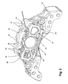
Figures 2 ,4A and 4B , the form of theinboard backplate 28 is different from theoutboard backplate 32. Theinboard backplate 28 is substantially thicker than the outboard backplate 32 (in this embodiment 15mm thick) by virtue of havingstiffening elements 40 and a centralcircular depression 42 to receive the head of thepiston 36 formed therein. Such an arrangement is desirable for theinboard pad 20 in order that it is able to receive the central loading from thepiston 36 during braking without appreciable flexing of the pad occurring. In other embodiments the arrangement of the backplate may be altered according to the particular requirements of the brake. - By contrast, the
outboard pad backplate 32 is a substantially planar cast component (without stiffening ribs) that is significantly thinner (approximately half as thin at 8mm) as theinboard backplate 28. It is possible to use athinner backplate 28 for theoutboard pad 24 because the backplate is supported across substantially all of its rear face by acorresponding support surface 44 of the caliper. - Nevertheless, despite the differences in the thickness and shape of the inboard and
outboard backplates formations 46 provided for the attachment of apad spring 48 are functionally the same. Specifically, their circumferential width and radial height are substantially the same. In addition, the thickness and dimensions of thefriction material - Thus, without the arrangement provided in the present invention, it is possible for the
outboard pad 24 to be fitted in theinboard opening 22, and for theinboard pad 20 to be fitted in theoutboard opening 26 in addition to the possibility of the pads being fitted with thefriction material outboard pad 24 in theinboard opening 22 in contact with thepiston 36 is undesirable, since this may lead to a flexing of the pad, thus limiting its useful life due to uneven wear or cracking of friction material because the centre of the pad proximate to the piston would wear more rapidly than the friction material at the circumferential ends thereof. - To combat this problem the
inboard pad 20 andoutboard pad 24 are provided with inboard andoutboard formations pad incorrect opening - Specifically, with reference to
Figure 1 andFigure 3 of the present invention, it can be seen that theopenings brake pads openings pad strap 54 that extends across aperture 17 over the pads and the pad springs 48, but enable the pads to advance towards the disc as they wear. - It can be seen in
Figure 3 that the horizontal abutment surfaces 52 to the left of thecarrier 18 as viewed inFigure 3 are substantially planar and merge directly into the adjacent upright abutment surfaces 50. At the right hand end, the horizontal abutment surfaces 52 comprise a feature in the form of a step. Theinboard step 56 is provided at the junction of the horizontal 52 andupright 50 abutment surfaces, as is theoutboard step 58. However, the shapes of the twosteps inboard step 56 is shallower in the radial direction, but wider in the circumferential direction than theoutboard step 58. Since thesteps openings gap 19. Furthermore, since the dimensions of thesteps openings steps - The inboard formation is a
notch 60 shaped to conform to the inboard step 56 (although the two need not actually be in contact when assembled) and the outboard formation is anotch 62 that conform to theoutboard step 58 in a similar way. This notch location is advantageous since it does not appreciably weaken the pads. - Thus, if an attempt is made to seat either
pad opening pad strap 54 to be secured over thebridge 16 and the brake could not therefore be properly assembled. -
Figures 5, 6A and 6B illustrate acarrier 118,outboard pad 124 andinboard pad 120 respectively according to another embodiment of the present invention. In this embodiment, like parts are labelled using like numerals, but with the addition of the prefix "1 ". - It can be seen from
Figure 5 that thesteps horizontal abutment surface 152. It can be seen that thetrough 156 is located towards the left hand side of thehorizontal abutment surface 152. Asimilar trough 158 is provided in the outboard right handhorizontal abutment surface 152, but is located towards the right hand side of the surface. Again, it is therefore apparent that theinboard opening 122 andoutboard opening 126 have neither rotational nor mirror symmetry. This means that by virtue of corresponding formations (in the form of downwardly projectinglugs 60 and 62) it is only possible to properly assemble the brake with thepads correct opening - Referring now to
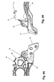
Figures 7 and 8 , a third embodiment of the present invention is illustrated. In this embodiment, like parts are illustrated by like numerals, but with the addition of the prefix "2". Only differences between the third embodiment and the preceding two embodiments are discussed in more detail. - This embodiment differs from the preceding embodiments in that the
outboard brake pad 224 is supported entirely by thecaliper 212. The carrier (not shown) only supports the inboard pad and does not extend over the rotor. This type of arrangement is shown in more detail inGB 2 413 162 - As a consequence of this arrangement, rather than the outboard opening being provided in the carrier, a
corresponding opening 226 is formed in thecaliper 212, so that as well as the caliper transferring the clamp load to the outboard brake pad viasurface 244, it additionally comprises the outboard upright abutment surfaces 250 and horizontal abutment surfaces 252 to transfer the torque loads to the carrier via thebridge 216 and housing (not shown). - This embodiment further differs in terms of the interface arrangement to prevent incorrect pad fitting. In this embodiment, the outboard interface is defined by a
lug 262 that does not extend through the entire depth of thehorizontal abutment surface 252. This is possible because the spatial relationship between theoutboard brake pad 224 andcaliper 212 remains fixed and no relative sliding of thepad 224 with respect to theupright 250 and horizontal 252 abutment surfaces occurs. - In this embodiment, an inboard pad having the same type of
notch 60 or lug 160 as in the first and second embodiments may be used since the different interface arrangements remain incompatible due to a lack of rotational and mirror symmetry to prevent the pads being fitted in the wrong location or in the wrong orientation. - It should be appreciated that the directional terms such as horizontal, upright, etc. should not be construed as limiting since brakes of the type described herein may be mounted in numerous orientations with respect to an axle and disc. Use of such terms is merely for the purposes of clarity and convenience.
- It should be understood that numerous changes may be made within the scope of the present invention. For example, numerous alternative shapes for the interface and locations of the interface may be provided on the pads and pad supports provided those arrangements do not result in an arrangement of inboard and outboard openings that have either rotational or mirror symmetry. In addition, the interface formation may be provided on a non-sliding surface of the openings (i.e. intermediate the horizontal support surfaces). In some instances it may be possible to provide the formations on the upright support surfaces or upright portions of the openings that do not act as sliding surfaces. A similar arrangement may be employed on fixed caliper, sliding rotor type disc brakes or on fixed caliper, fixed rotor brakes which have means for directly driving the outboard pad. The backplates may be forged, stamped or fabricated rather than being cast.
Claims (15)
- A disc brake (10) comprising:an actuation mechanism (12);first (22) and second (26) brake pad mounting structures to be located, in use, adjacent opposing inboard and outboard faces respectively of a brake rotor to be braked;first (20) and second (24) brake pads located by the first (22) and second (26) mounting structures respectively such that upon application of the actuation mechanism the pads (20, 24) clamp the rotor and brake torque is reacted by the pad mounting structures (22, 26), the first pad (20) having a different functional requirement to the second pad (24) such that fitment of the first pad (20) in the second structure (26) and/or the second pad (24) in the first structure (22) impairs the safety, functionality or durability of the brake (10);wherein to prevent or inhibit such incorrect fitting, the first pad (20) comprises on a peripheral face or rear face thereof a first formation (60) in such a location that it may only be successfully fitted in the first mounting structure (22) and only successfully fitted in the correct orientation with the brake (10) fully assembled and the second pad (24) comprises a second formation (62) different from the first (60) such that it may only be successfully fitted in the second mounting structure (26) and only successfully fitted in the correct orientation with the brake (10) fully assembled.
- A disc brake (10) according to claim 1 wherein the first (20) and second (24) pads comprise backplates (28, 32) and the first pad (20) has a thicker backplate (28) than the second pad (24).
- A disc brake (10) according to claim 1 or claim 2 wherein the first pad (20) has a form (42) to engage a piston or tappet of the brake (10).
- A disc brake (10) according to any preceding claim wherein the second pad (24) has a formation to be supported in a corresponding structure of a bridge portion (16) of a caliper (12) of the brake.
- A disc brake (10) according to any of claims 1 to 3 wherein the second pad (24) has a formation to be supported in a structure of a carrier (18) of the brake (10).
- A disc brake (10) according to any preceding claim wherein the formation (60, 62) of at least one of the first (20) and second (24) pads is on a bottom edge thereof.
- A disc brake (10) according to any preceding claim wherein a formation (60, 62) of at least one of the pads (20, 24) is on a rear face thereof.
- A disc brake (10) according to any preceding claim wherein the formation (60, 62) of at least one of the pads is on a side edge thereof.
- A disc brake (10) according to any preceding claim wherein a formation (60, 62) of at least one of the pads is on a top edge thereof.
- A disc brake (10) according to any preceding claim wherein a formation (60, 62) on at least one of the first (20) and second (24) brake pads comprises a projection or recess to engage with a corresponding feature in the mounting structure (22, 26).
- A disc brake (10) according to any preceding claim wherein the first (20) and second (24) pads further comprise substantially identical structures (46) for attachment of pad springs (48).
- A disc brake (10) according to any preceding claim further comprising an aperture (17) for the fitting and removal of the pads (20, 24) in a radial direction; preferably wherein the aperture (17) permits the fitting and removal of the pads (20, 24) to be achieved with the brake disc being in place.
- A disc brake (10) according to any preceding claim wherein the pads (20, 24) are configured to be retained radially in the mounting structures (22, 26) by a pad strap (54), preferably wherein the pad strap (54) is prevented from being secured over the pads (20, 24) if the pads are incorrectly orientated and located.
- A disc brake (10) according to any preceding claim wherein fitting the first (20) and second (24) pads in the corresponding first (22) and second (26) locations and in the correct orientations is the only way of assembling a fully functional brake (10).
- First (20) and second (24) disc brake pads for fitment in first (22 and second (26) mounting structures of a disc brake (10) inboard and outboard of a brake rotor, the first pad (20) having a different functional requirement to the second pad (24) such that fitment of the first pad (20) in the second structure (26) and/or the second pad (24) in the first structure (22) would impair the safety, functionality and/or durability of the brake (10);
wherein to prevent or inhibit such incorrect fitting, the first pad (20) comprises on a peripheral face or a rear face thereof a first formation (60) and the second pad (24) comprises on a peripheral face or a rear face thereof a second formation (62), the first (60) and second (62) formations being arranged such that the first (20) and second (24) pads have neither mirror symmetry nor rotational symmetry when assembled in the brake (10) and cannot be fitted in an incorrect location or incorrect orientation when the brake (10) has corresponding features within the mounting structures (22, 26) thereof, the first (20) and second (24) disc brake pads preferably further comprising substantially identical structures (46) for the attachment of pad springs (48).
Priority Applications (1)
| Application Number | Priority Date | Filing Date | Title |
|---|---|---|---|
| PL09179350T PL2199640T5 (en) | 2008-12-16 | 2009-12-15 | A disc brake |
Applications Claiming Priority (1)
| Application Number | Priority Date | Filing Date | Title |
|---|---|---|---|
| GBGB0822898.3A GB0822898D0 (en) | 2008-12-16 | 2008-12-16 | A disc brake |
Publications (3)
| Publication Number | Publication Date |
|---|---|
| EP2199640A1 EP2199640A1 (en) | 2010-06-23 |
| EP2199640B1 true EP2199640B1 (en) | 2012-10-17 |
| EP2199640B2 EP2199640B2 (en) | 2017-07-05 |
Family
ID=40326184
Family Applications (1)
| Application Number | Title | Priority Date | Filing Date |
|---|---|---|---|
| EP09179350.5A Active EP2199640B2 (en) | 2008-12-16 | 2009-12-15 | A disc brake |
Country Status (6)
| Country | Link |
|---|---|
| US (1) | US7926631B2 (en) |
| EP (1) | EP2199640B2 (en) |
| CN (1) | CN101749339A (en) |
| BR (1) | BRPI0905113A2 (en) |
| GB (1) | GB0822898D0 (en) |
| PL (1) | PL2199640T5 (en) |
Cited By (1)
| Publication number | Priority date | Publication date | Assignee | Title |
|---|---|---|---|---|
| EP2420690B1 (en) | 2010-08-18 | 2015-03-04 | KNORR-BREMSE Systeme für Nutzfahrzeuge GmbH | Disc brake, in particular for a commercial vehicle |
Families Citing this family (27)
| Publication number | Priority date | Publication date | Assignee | Title |
|---|---|---|---|---|
| DE102011118314B4 (en) * | 2011-11-11 | 2013-09-26 | Wabco Radbremsen Gmbh | DISC BRAKE, ESPECIALLY FOR COMMERCIAL VEHICLES, BRAKE PAD AND PRESSURE PLATE AS SEPARATE COMPONENTS FOR SUCH A DISC BRAKE |
| US20130333990A1 (en) * | 2012-06-13 | 2013-12-19 | Amsted Rail Company, Inc. | Railcar brake beam wear liner |
| GB201211722D0 (en) * | 2012-07-02 | 2012-08-15 | Meritor Heavy Vehicle Braking | A disc brake |
| US8960381B2 (en) | 2012-08-17 | 2015-02-24 | Bendix Spicer Foundation Brake Llc | Disc brake pad mounting and retention system and method |
| US8973240B2 (en) | 2012-08-17 | 2015-03-10 | Bendix Spicer Foundation Brake Llc | Disc brake pad mounting and retention system and method |
| US8973720B2 (en) | 2012-08-17 | 2015-03-10 | Bendix Spicer Foundation Brake Llc | Disc brake pad mounting and retention system and method |
| US8540061B1 (en) | 2012-08-17 | 2013-09-24 | Bendix Spicer Foundation Brake Llc | Disc brake pad mounting and retention system and method |
| US8544614B1 (en) | 2012-08-17 | 2013-10-01 | Bendix Spicer Foundation Brake Llc | Disc brake pad mounting and retention system and method |
| DE102013012547B4 (en) * | 2013-07-29 | 2021-08-19 | Wabco Europe Bvba | Disc brakes, in particular for commercial vehicles, and brake linings for such a disc brake |
| USD822563S1 (en) * | 2014-07-17 | 2018-07-10 | Dennis Michael Nosworthy | Disc brake caliper bracket |
| US10247266B2 (en) | 2014-10-30 | 2019-04-02 | Bwi (Shanghai) Co., Ltd. | Brake mounting bracket apparatus |
| MX2017006342A (en) * | 2014-11-19 | 2017-08-21 | Hitachi Automotive Systems Ltd | Disc brake. |
| DE102017105641B4 (en) * | 2017-03-16 | 2022-09-15 | Knorr-Bremse Systeme für Nutzfahrzeuge GmbH | Brake carrier and disc brake |
| PL3458738T3 (en) * | 2016-05-20 | 2023-05-08 | Knorr-Bremse Systeme für Nutzfahrzeuge GmbH | Disc brake for a commercial vehicle, brake pad, and brake pad set |
| GB2563078A (en) * | 2017-06-02 | 2018-12-05 | Meritor Heavy Vehicle Braking Systems Uk Ltd | A brake pad |
| GB2563081A (en) | 2017-06-02 | 2018-12-05 | Meritor Heavy Vehicle Braking Systems Uk Ltd | A brake pad |
| GB2563079A (en) | 2017-06-02 | 2018-12-05 | Meritor Heavy Vehicle Braking Systems Uk Ltd | A disc brake |
| CN109281961B (en) * | 2017-07-21 | 2021-03-12 | 英国美瑞特重型车制动系统有限公司 | Disc brake |
| EP3431801B1 (en) | 2017-07-21 | 2022-09-07 | Meritor Heavy Vehicle Braking Systems (UK) Limited | A disc brake |
| EP3450792A1 (en) | 2017-08-31 | 2019-03-06 | Meritor Heavy Vehicle Braking Systems (UK) Limited | A disc brake |
| EP3450789B1 (en) | 2017-08-31 | 2021-05-26 | Meritor Heavy Vehicle Braking Systems (UK) Limited | A disc brake |
| US10400837B2 (en) * | 2017-10-11 | 2019-09-03 | Arvinmeritor Technology, Llc | Brake carrier and method of manufacture |
| EP3492767B1 (en) * | 2017-11-29 | 2020-11-18 | Meritor Heavy Vehicle Braking Systems (UK) Limited | A disc brake |
| CN110748584A (en) * | 2019-12-11 | 2020-02-04 | 隆中控股集团股份有限公司 | Brake bracket and brake |
| KR20210098641A (en) * | 2020-02-03 | 2021-08-11 | 주식회사 만도 | Pad spring for vehicle braking apparatus |
| USD1029715S1 (en) * | 2022-11-09 | 2024-06-04 | Ausco Products, Inc. | Brake housing |
| DE102022134788A1 (en) | 2022-12-23 | 2024-07-04 | Bpw Bergische Achsen Kommanditgesellschaft | Brake pad, brake disc assembly and kit for repair and maintenance of a brake disc assembly |
Family Cites Families (23)
| Publication number | Priority date | Publication date | Assignee | Title |
|---|---|---|---|---|
| DE2838921C2 (en) | 1978-09-07 | 1986-09-04 | Alfred Teves Gmbh, 6000 Frankfurt | Floating caliper disc brake |
| US4391355A (en) † | 1979-12-03 | 1983-07-05 | Kelsey-Hayes Company | Sliding caliper disc brake |
| JPS5740128A (en) * | 1980-08-20 | 1982-03-05 | Tokico Ltd | Disc brake |
| EP0139890B1 (en) | 1983-08-31 | 1989-04-26 | Rockwell International Corporation | Friction pad and support for a disc brake |
| DE3816109A1 (en) | 1988-05-11 | 1989-11-23 | Teves Gmbh Alfred | DISC BRAKE WITH UNMISTAKABLE BRAKE PADS |
| DE4126339C2 (en) * | 1991-08-09 | 2002-04-04 | Continental Teves Ag & Co Ohg | Part floating disc brake for high-performance vehicles |
| DE4340454A1 (en) * | 1993-11-27 | 1995-06-01 | Teves Gmbh Alfred | Brake pad set for floating caliper disc brake |
| JP3409130B2 (en) | 1994-05-31 | 2003-05-26 | トキコ株式会社 | Disc brake |
| GB9513709D0 (en) | 1995-07-05 | 1995-09-06 | Lucas Ind Plc | Disc brake |
| FR2778711B1 (en) † | 1998-05-14 | 2000-07-13 | Bosch Syst Freinage | FLOATING CALIPER DISC BRAKE |
| JP2000110859A (en) | 1998-10-02 | 2000-04-18 | Akebono Brake Ind Co Ltd | Disc brake |
| AT4109U1 (en) | 1999-09-21 | 2001-01-25 | Egston Eggenburger Syst Elektr | WINDING BODY FOR A ROGOWSKY COIL WITH COUNTERWIND |
| BR0303128B1 (en) † | 2002-08-06 | 2014-10-29 | Meritor Heavy Vehicle Braking | BRAKE CALIBRATOR |
| GB0301798D0 (en) * | 2003-01-25 | 2003-02-26 | Meritor Heavy Vehicle Braking | Force transmission device for a disc brake |
| GB0301799D0 (en) * | 2003-01-25 | 2003-02-26 | Meritor Heavy Vehicle Braking | Disc brake pad hold down spring and backplate |
| ES2289383T3 (en) † | 2003-04-28 | 2008-02-01 | Bpw Bergische Achsen Kommanditgesellschaft | CLAMP HOLDER FOR A DISC BRAKE, AS WELL AS A BRAKE LINING FOR A DISC BRAKE. |
| US7318503B2 (en) * | 2004-04-26 | 2008-01-15 | Akebono Corporation (North America) | Pad retaining clips |
| DE102005001482A1 (en) | 2005-01-12 | 2006-07-20 | Gustav Magenwirth Gmbh & Co. Kg | Brake calliper and brake pad for a brake calliper |
| DE102005050581B3 (en) * | 2005-10-21 | 2007-06-06 | Knorr-Bremse Systeme für Nutzfahrzeuge GmbH | Disc brake, in particular for a commercial vehicle |
| DE102006003748B4 (en) * | 2006-01-26 | 2017-01-26 | Knorr-Bremse Systeme für Nutzfahrzeuge GmbH | Disc brake, in particular for a commercial vehicle |
| DE102007006472A1 (en) | 2006-04-20 | 2007-11-08 | Continental Teves Ag & Co. Ohg | Disk brake for motor vehicle, has central supports with radial wall thickness that is designed such that spacing between central supports and rotational axis of brake disk is smaller than outer radius of disk, in axial region of linings |
| GB0608955D0 (en) | 2006-05-05 | 2006-06-14 | Meritor Heavy Vehicle Braking | Disc brake operating mechanism |
| US7597178B2 (en) | 2007-05-31 | 2009-10-06 | Ausco Products, Inc. | Caliper brake |
-
2008
- 2008-12-16 GB GBGB0822898.3A patent/GB0822898D0/en not_active Ceased
-
2009
- 2009-12-14 US US12/637,117 patent/US7926631B2/en active Active
- 2009-12-15 PL PL09179350T patent/PL2199640T5/en unknown
- 2009-12-15 EP EP09179350.5A patent/EP2199640B2/en active Active
- 2009-12-16 BR BRPI0905113-9A patent/BRPI0905113A2/en not_active Application Discontinuation
- 2009-12-16 CN CN200910258053A patent/CN101749339A/en active Pending
Cited By (1)
| Publication number | Priority date | Publication date | Assignee | Title |
|---|---|---|---|---|
| EP2420690B1 (en) | 2010-08-18 | 2015-03-04 | KNORR-BREMSE Systeme für Nutzfahrzeuge GmbH | Disc brake, in particular for a commercial vehicle |
Also Published As
| Publication number | Publication date |
|---|---|
| PL2199640T5 (en) | 2018-01-31 |
| EP2199640B2 (en) | 2017-07-05 |
| PL2199640T3 (en) | 2013-02-28 |
| US7926631B2 (en) | 2011-04-19 |
| BRPI0905113A2 (en) | 2011-02-08 |
| CN101749339A (en) | 2010-06-23 |
| US20100147639A1 (en) | 2010-06-17 |
| EP2199640A1 (en) | 2010-06-23 |
| GB0822898D0 (en) | 2009-01-21 |
Similar Documents
| Publication | Publication Date | Title |
|---|---|---|
| EP2199640B1 (en) | A disc brake | |
| EP1391628B1 (en) | Brake pad and brake caliper for disc brakes | |
| US7631733B2 (en) | Brake assembly | |
| EP2682631B1 (en) | A disc brake | |
| EP1649185B1 (en) | Spring member for disc-brake calipers and disc-brake caliper | |
| JP7523624B2 (en) | Disc brakes and cover parts | |
| US10801569B2 (en) | Disc brake | |
| EP3680504B1 (en) | Vehicular disc brake | |
| EP3954919B1 (en) | Brake assembly | |
| US20040262099A1 (en) | Flat spring for preloading disc brake pads | |
| CN111094783A (en) | Caliper for opposed piston type disc brake | |
| JP6928564B2 (en) | Vehicle disc brakes | |
| EP1647733B1 (en) | Brake pad | |
| JP5510144B2 (en) | Disc brake | |
| JP4288197B2 (en) | Vehicle disc brake | |
| EP3450791A1 (en) | A friction element |
Legal Events
| Date | Code | Title | Description |
|---|---|---|---|
| PUAI | Public reference made under article 153(3) epc to a published international application that has entered the european phase |
Free format text: ORIGINAL CODE: 0009012 |
|
| AK | Designated contracting states |
Kind code of ref document: A1 Designated state(s): AT BE BG CH CY CZ DE DK EE ES FI FR GB GR HR HU IE IS IT LI LT LU LV MC MK MT NL NO PL PT RO SE SI SK SM TR |
|
| AX | Request for extension of the european patent |
Extension state: AL BA RS |
|
| 17P | Request for examination filed |
Effective date: 20101214 |
|
| 17Q | First examination report despatched |
Effective date: 20110218 |
|
| GRAP | Despatch of communication of intention to grant a patent |
Free format text: ORIGINAL CODE: EPIDOSNIGR1 |
|
| GRAS | Grant fee paid |
Free format text: ORIGINAL CODE: EPIDOSNIGR3 |
|
| GRAA | (expected) grant |
Free format text: ORIGINAL CODE: 0009210 |
|
| AK | Designated contracting states |
Kind code of ref document: B1 Designated state(s): AT BE BG CH CY CZ DE DK EE ES FI FR GB GR HR HU IE IS IT LI LT LU LV MC MK MT NL NO PL PT RO SE SI SK SM TR |
|
| REG | Reference to a national code |
Ref country code: GB Ref legal event code: FG4D |
|
| REG | Reference to a national code |
Ref country code: CH Ref legal event code: EP |
|
| REG | Reference to a national code |
Ref country code: IE Ref legal event code: FG4D |
|
| REG | Reference to a national code |
Ref country code: AT Ref legal event code: REF Ref document number: 580048 Country of ref document: AT Kind code of ref document: T Effective date: 20121115 |
|
| REG | Reference to a national code |
Ref country code: SE Ref legal event code: TRGR |
|
| REG | Reference to a national code |
Ref country code: DE Ref legal event code: R096 Ref document number: 602009010450 Country of ref document: DE Effective date: 20121213 |
|
| REG | Reference to a national code |
Ref country code: DE Ref legal event code: R082 Ref document number: 602009010450 Country of ref document: DE |
|
| REG | Reference to a national code |
Ref country code: PL Ref legal event code: T3 |
|
| REG | Reference to a national code |
Ref country code: AT Ref legal event code: MK05 Ref document number: 580048 Country of ref document: AT Kind code of ref document: T Effective date: 20121017 |
|
| REG | Reference to a national code |
Ref country code: NL Ref legal event code: VDEP Effective date: 20121017 |
|
| REG | Reference to a national code |
Ref country code: LT Ref legal event code: MG4D |
|
| PG25 | Lapsed in a contracting state [announced via postgrant information from national office to epo] |
Ref country code: IS Free format text: LAPSE BECAUSE OF FAILURE TO SUBMIT A TRANSLATION OF THE DESCRIPTION OR TO PAY THE FEE WITHIN THE PRESCRIBED TIME-LIMIT Effective date: 20130217 Ref country code: NL Free format text: LAPSE BECAUSE OF FAILURE TO SUBMIT A TRANSLATION OF THE DESCRIPTION OR TO PAY THE FEE WITHIN THE PRESCRIBED TIME-LIMIT Effective date: 20121017 Ref country code: LT Free format text: LAPSE BECAUSE OF FAILURE TO SUBMIT A TRANSLATION OF THE DESCRIPTION OR TO PAY THE FEE WITHIN THE PRESCRIBED TIME-LIMIT Effective date: 20121017 Ref country code: HR Free format text: LAPSE BECAUSE OF FAILURE TO SUBMIT A TRANSLATION OF THE DESCRIPTION OR TO PAY THE FEE WITHIN THE PRESCRIBED TIME-LIMIT Effective date: 20121017 Ref country code: FI Free format text: LAPSE BECAUSE OF FAILURE TO SUBMIT A TRANSLATION OF THE DESCRIPTION OR TO PAY THE FEE WITHIN THE PRESCRIBED TIME-LIMIT Effective date: 20121017 Ref country code: ES Free format text: LAPSE BECAUSE OF FAILURE TO SUBMIT A TRANSLATION OF THE DESCRIPTION OR TO PAY THE FEE WITHIN THE PRESCRIBED TIME-LIMIT Effective date: 20130128 Ref country code: NO Free format text: LAPSE BECAUSE OF FAILURE TO SUBMIT A TRANSLATION OF THE DESCRIPTION OR TO PAY THE FEE WITHIN THE PRESCRIBED TIME-LIMIT Effective date: 20130117 |
|
| PG25 | Lapsed in a contracting state [announced via postgrant information from national office to epo] |
Ref country code: LV Free format text: LAPSE BECAUSE OF FAILURE TO SUBMIT A TRANSLATION OF THE DESCRIPTION OR TO PAY THE FEE WITHIN THE PRESCRIBED TIME-LIMIT Effective date: 20121017 Ref country code: SI Free format text: LAPSE BECAUSE OF FAILURE TO SUBMIT A TRANSLATION OF THE DESCRIPTION OR TO PAY THE FEE WITHIN THE PRESCRIBED TIME-LIMIT Effective date: 20121017 Ref country code: BE Free format text: LAPSE BECAUSE OF FAILURE TO SUBMIT A TRANSLATION OF THE DESCRIPTION OR TO PAY THE FEE WITHIN THE PRESCRIBED TIME-LIMIT Effective date: 20121017 Ref country code: PT Free format text: LAPSE BECAUSE OF FAILURE TO SUBMIT A TRANSLATION OF THE DESCRIPTION OR TO PAY THE FEE WITHIN THE PRESCRIBED TIME-LIMIT Effective date: 20130218 Ref country code: GR Free format text: LAPSE BECAUSE OF FAILURE TO SUBMIT A TRANSLATION OF THE DESCRIPTION OR TO PAY THE FEE WITHIN THE PRESCRIBED TIME-LIMIT Effective date: 20130118 |
|
| PG25 | Lapsed in a contracting state [announced via postgrant information from national office to epo] |
Ref country code: AT Free format text: LAPSE BECAUSE OF FAILURE TO SUBMIT A TRANSLATION OF THE DESCRIPTION OR TO PAY THE FEE WITHIN THE PRESCRIBED TIME-LIMIT Effective date: 20121017 |
|
| PLBI | Opposition filed |
Free format text: ORIGINAL CODE: 0009260 |
|
| PG25 | Lapsed in a contracting state [announced via postgrant information from national office to epo] |
Ref country code: BG Free format text: LAPSE BECAUSE OF FAILURE TO SUBMIT A TRANSLATION OF THE DESCRIPTION OR TO PAY THE FEE WITHIN THE PRESCRIBED TIME-LIMIT Effective date: 20130117 Ref country code: DK Free format text: LAPSE BECAUSE OF FAILURE TO SUBMIT A TRANSLATION OF THE DESCRIPTION OR TO PAY THE FEE WITHIN THE PRESCRIBED TIME-LIMIT Effective date: 20121017 Ref country code: EE Free format text: LAPSE BECAUSE OF FAILURE TO SUBMIT A TRANSLATION OF THE DESCRIPTION OR TO PAY THE FEE WITHIN THE PRESCRIBED TIME-LIMIT Effective date: 20121017 Ref country code: MC Free format text: LAPSE BECAUSE OF NON-PAYMENT OF DUE FEES Effective date: 20121231 Ref country code: SK Free format text: LAPSE BECAUSE OF FAILURE TO SUBMIT A TRANSLATION OF THE DESCRIPTION OR TO PAY THE FEE WITHIN THE PRESCRIBED TIME-LIMIT Effective date: 20121017 |
|
| 26 | Opposition filed |
Opponent name: VRI-VERBAND DER REIBBELAGINDUSTRIE E.V. Effective date: 20130717 |
|
| PLAX | Notice of opposition and request to file observation + time limit sent |
Free format text: ORIGINAL CODE: EPIDOSNOBS2 |
|
| PG25 | Lapsed in a contracting state [announced via postgrant information from national office to epo] |
Ref country code: RO Free format text: LAPSE BECAUSE OF FAILURE TO SUBMIT A TRANSLATION OF THE DESCRIPTION OR TO PAY THE FEE WITHIN THE PRESCRIBED TIME-LIMIT Effective date: 20121017 |
|
| REG | Reference to a national code |
Ref country code: IE Ref legal event code: MM4A |
|
| REG | Reference to a national code |
Ref country code: DE Ref legal event code: R026 Ref document number: 602009010450 Country of ref document: DE Effective date: 20130717 |
|
| PG25 | Lapsed in a contracting state [announced via postgrant information from national office to epo] |
Ref country code: IE Free format text: LAPSE BECAUSE OF NON-PAYMENT OF DUE FEES Effective date: 20121215 |
|
| PG25 | Lapsed in a contracting state [announced via postgrant information from national office to epo] |
Ref country code: CY Free format text: LAPSE BECAUSE OF FAILURE TO SUBMIT A TRANSLATION OF THE DESCRIPTION OR TO PAY THE FEE WITHIN THE PRESCRIBED TIME-LIMIT Effective date: 20121017 Ref country code: MT Free format text: LAPSE BECAUSE OF FAILURE TO SUBMIT A TRANSLATION OF THE DESCRIPTION OR TO PAY THE FEE WITHIN THE PRESCRIBED TIME-LIMIT Effective date: 20121017 |
|
| PLAF | Information modified related to communication of a notice of opposition and request to file observations + time limit |
Free format text: ORIGINAL CODE: EPIDOSCOBS2 |
|
| PLBB | Reply of patent proprietor to notice(s) of opposition received |
Free format text: ORIGINAL CODE: EPIDOSNOBS3 |
|
| PG25 | Lapsed in a contracting state [announced via postgrant information from national office to epo] |
Ref country code: TR Free format text: LAPSE BECAUSE OF FAILURE TO SUBMIT A TRANSLATION OF THE DESCRIPTION OR TO PAY THE FEE WITHIN THE PRESCRIBED TIME-LIMIT Effective date: 20121017 |
|
| PG25 | Lapsed in a contracting state [announced via postgrant information from national office to epo] |
Ref country code: LU Free format text: LAPSE BECAUSE OF NON-PAYMENT OF DUE FEES Effective date: 20121215 Ref country code: SM Free format text: LAPSE BECAUSE OF FAILURE TO SUBMIT A TRANSLATION OF THE DESCRIPTION OR TO PAY THE FEE WITHIN THE PRESCRIBED TIME-LIMIT Effective date: 20121017 |
|
| PG25 | Lapsed in a contracting state [announced via postgrant information from national office to epo] |
Ref country code: HU Free format text: LAPSE BECAUSE OF FAILURE TO SUBMIT A TRANSLATION OF THE DESCRIPTION OR TO PAY THE FEE WITHIN THE PRESCRIBED TIME-LIMIT Effective date: 20091215 |
|
| REG | Reference to a national code |
Ref country code: CH Ref legal event code: PL |
|
| PG25 | Lapsed in a contracting state [announced via postgrant information from national office to epo] |
Ref country code: LI Free format text: LAPSE BECAUSE OF NON-PAYMENT OF DUE FEES Effective date: 20131231 Ref country code: CH Free format text: LAPSE BECAUSE OF NON-PAYMENT OF DUE FEES Effective date: 20131231 |
|
| PG25 | Lapsed in a contracting state [announced via postgrant information from national office to epo] |
Ref country code: MK Free format text: LAPSE BECAUSE OF FAILURE TO SUBMIT A TRANSLATION OF THE DESCRIPTION OR TO PAY THE FEE WITHIN THE PRESCRIBED TIME-LIMIT Effective date: 20121017 |
|
| REG | Reference to a national code |
Ref country code: FR Ref legal event code: PLFP Year of fee payment: 7 |
|
| PLAB | Opposition data, opponent's data or that of the opponent's representative modified |
Free format text: ORIGINAL CODE: 0009299OPPO |
|
| R26 | Opposition filed (corrected) |
Opponent name: VRI-VERBAND DER REIBBELAGINDUSTRIE E.V. Effective date: 20130717 |
|
| APBM | Appeal reference recorded |
Free format text: ORIGINAL CODE: EPIDOSNREFNO |
|
| APBP | Date of receipt of notice of appeal recorded |
Free format text: ORIGINAL CODE: EPIDOSNNOA2O |
|
| APAH | Appeal reference modified |
Free format text: ORIGINAL CODE: EPIDOSCREFNO |
|
| REG | Reference to a national code |
Ref country code: FR Ref legal event code: PLFP Year of fee payment: 8 |
|
| PG25 | Lapsed in a contracting state [announced via postgrant information from national office to epo] |
Ref country code: IT Free format text: LAPSE BECAUSE OF NON-PAYMENT OF DUE FEES Effective date: 20151215 |
|
| APBU | Appeal procedure closed |
Free format text: ORIGINAL CODE: EPIDOSNNOA9O |
|
| PUAH | Patent maintained in amended form |
Free format text: ORIGINAL CODE: 0009272 |
|
| STAA | Information on the status of an ep patent application or granted ep patent |
Free format text: STATUS: PATENT MAINTAINED AS AMENDED |
|
| 27A | Patent maintained in amended form |
Effective date: 20170705 |
|
| AK | Designated contracting states |
Kind code of ref document: B2 Designated state(s): AT BE BG CH CY CZ DE DK EE ES FI FR GB GR HR HU IE IS IT LI LT LU LV MC MK MT NL NO PL PT RO SE SI SK SM TR |
|
| REG | Reference to a national code |
Ref country code: DE Ref legal event code: R102 Ref document number: 602009010450 Country of ref document: DE |
|
| PG25 | Lapsed in a contracting state [announced via postgrant information from national office to epo] |
Ref country code: IT Free format text: LAPSE BECAUSE OF NON-PAYMENT OF DUE FEES Effective date: 20151215 |
|
| PGRI | Patent reinstated in contracting state [announced from national office to epo] |
Ref country code: IT Effective date: 20170710 |
|
| REG | Reference to a national code |
Ref country code: SE Ref legal event code: RPEO |
|
| REG | Reference to a national code |
Ref country code: FR Ref legal event code: PLFP Year of fee payment: 9 |
|
| P01 | Opt-out of the competence of the unified patent court (upc) registered |
Effective date: 20230531 |
|
| PGFP | Annual fee paid to national office [announced via postgrant information from national office to epo] |
Ref country code: GB Payment date: 20231227 Year of fee payment: 15 |
|
| PGFP | Annual fee paid to national office [announced via postgrant information from national office to epo] |
Ref country code: SE Payment date: 20231227 Year of fee payment: 15 Ref country code: IT Payment date: 20231220 Year of fee payment: 15 Ref country code: FR Payment date: 20231227 Year of fee payment: 15 Ref country code: CZ Payment date: 20231127 Year of fee payment: 15 |
|
| PGFP | Annual fee paid to national office [announced via postgrant information from national office to epo] |
Ref country code: PL Payment date: 20231123 Year of fee payment: 15 |
|
| PGFP | Annual fee paid to national office [announced via postgrant information from national office to epo] |
Ref country code: DE Payment date: 20231229 Year of fee payment: 15 |