JP2005291331A - Vehicle disc brake - Google Patents
Vehicle disc brake Download PDFInfo
- Publication number
- JP2005291331A JP2005291331A JP2004106162A JP2004106162A JP2005291331A JP 2005291331 A JP2005291331 A JP 2005291331A JP 2004106162 A JP2004106162 A JP 2004106162A JP 2004106162 A JP2004106162 A JP 2004106162A JP 2005291331 A JP2005291331 A JP 2005291331A
- Authority
- JP
- Japan
- Prior art keywords
- retainer
- pad spring
- caliper body
- disc brake
- vehicle
- Prior art date
- Legal status (The legal status is an assumption and is not a legal conclusion. Google has not performed a legal analysis and makes no representation as to the accuracy of the status listed.)
- Pending
Links
Images

Landscapes
- Braking Arrangements (AREA)
Abstract
Description
本発明は車両用ディスクブレーキに関し、より詳細には車両用ディスクブレーキに取り付けられるパッドスプリングあるいはリテーナと、車両用ディスクブレーキの部品との間における電食作用を防止する車両用ディスクブレーキに関する。 The present invention relates to a vehicular disc brake, and more particularly to a vehicular disc brake that prevents electrolytic corrosion between a pad spring or a retainer attached to the vehicular disc brake and components of the vehicular disc brake.
車両用ディスクブレーキでは、キャリパブラケットにキャリパボディと摩擦パッドをディスクロータの軸線方向に可動に支持した製品が知られている。この車両用ディスクブレーキでは、制動作用を停止した際などに摩擦パッドががたつくことがあることから、キャリパボディのブリッジ部にパッドスプリングを取り付け、パッドスプリングにより摩擦パッドを弾性的に押圧して摩擦パッドのがたつきを防止するように構成されている(たとえば、特許文献1参照)。
また、摩擦パッドを支持するバックプレートとキャリパブラケットとが当接する部位に、ステンレス板等からなるリテーナを配置して、摩擦パッドのディスクロータの軸線方向への動きが円滑になるように構成されている。
Further, a retainer made of a stainless steel plate or the like is disposed at a portion where the back plate supporting the friction pad and the caliper bracket come into contact with each other so that the friction pad moves smoothly in the axial direction of the disk rotor. Yes.
ところで、近年は、軽量化を目的として車両用ディスクブレーキを構成する部品が鉄系材料からアルミニウムあるいはその合金によって製作されるようになってきた。たとえば、車両用ディスクブレーキではキャリパボディ10をアルミニウム合金製とした製品が提供されている。
このようにキャリパボディ10をアルミニウムあるいはその合金で製作した場合には、アルミニウムあるいはその合金以外からなる部品がキャリパボディと接触する部位において、異種金属による電食作用が生じる場合がある。
上述したパッドスプリングおよびリテーナは鉄系材料からなるから、パッドスプリングとキャリパボディあるいはリテーナとキャリパボディとが接触する部位で、電食作用が生じる可能性がある。
By the way, in recent years, components constituting a vehicle disc brake have been manufactured from an iron-based material using aluminum or an alloy thereof for the purpose of reducing the weight. For example, a product in which the
When the
Since the pad spring and the retainer described above are made of an iron-based material, there is a possibility that an electrolytic corrosion action may occur at a portion where the pad spring and the caliper body or the retainer and the caliper body are in contact with each other.
本発明は、このように、アルミニウム合金からなるキャリパボディを備えた車両用ディスクブレーキの場合のように、車両用ディスクブレーキに用いられるパッドスプリングあるいはリテーナと異種金属からなる部品とが接触等することによって電食作用が生じることを防止するようにした車両用ディスクブレーキを提供することを目的とする。 In the present invention, as in the case of a vehicle disc brake having a caliper body made of an aluminum alloy, the pad spring or retainer used in the vehicle disc brake is in contact with a component made of a different metal. An object of the present invention is to provide a vehicular disc brake which prevents the occurrence of an electrolytic corrosion action.
本発明は上記目的を達成するため次の構成を備える。
すなわち、パッドスプリング、およびパッドスプリングとは異種金属からなる部品とを有する車両用ディスクブレーキであって、前記パッドスプリングと前記部品との間に電気的な絶縁体を介在させることを特徴とする。
また、リテーナ、およびリテーナとは異種金属からなる部品とを有する車両用ディスクブレーキであって、前記リテーナと前記部品との間に電気的な絶縁体を介在させることを特徴とする。
In order to achieve the above object, the present invention comprises the following arrangement.
That is, it is a vehicle disc brake having a pad spring and a part made of a different metal from the pad spring, and an electrical insulator is interposed between the pad spring and the part.
The retainer and the retainer are vehicle disc brakes having parts made of dissimilar metals, and an electrical insulator is interposed between the retainer and the parts.
また、前記絶縁体が、前記パッドスプリングと前記部品とが当接する部位および近接する部位を覆うカバー部を備えること、また、前記絶縁体が、前記リテーナと前記部品とが当接する部位および近接する部位を覆うカバー部を備えることにより、パッドスプリングと部品との間、およびリテーナと部品との間で電食作用が生じることをさらに確実に防止することが可能となる。
また、前記部品がキャリパボディであって、前記カバー部が、前記キャリパボディに形成された開口部に係止されるパッドスプリングのフック部の、少なくとも前記キャリパボディとの当接部を覆うことにより、パッドスプリングとキャリパボディとの間の電食作用を防止することができる。
また、前記部品がキャリパボディであって、前記カバー部が、前記リテーナの、前記キャリパボディのブリッジ部の側面に近接する先端部を覆うことにより、リテーナとキャリパボディとの間の電食作用を防止することができる。
また、前記カバー部が、着脱可能な弾性カバーであることにより、従来のパッドスプリングあるいはリテーナに弾性カバーを装着することによって容易に電食作用を防止するパッドスプリングあるいはリテーナとして使用することが可能になる。
In addition, the insulator includes a cover portion that covers a portion where the pad spring and the component abut and a portion where the pad spring abuts, and the insulator is located close to a portion where the retainer and the component abut. By providing the cover portion that covers the portion, it is possible to more reliably prevent the occurrence of an electrolytic corrosion action between the pad spring and the component and between the retainer and the component.
The component is a caliper body, and the cover portion covers at least a contact portion of the hook portion of a pad spring that is locked to an opening formed in the caliper body with the caliper body. Electrolytic corrosion action between the pad spring and the caliper body can be prevented.
In addition, the component is a caliper body, and the cover portion covers an end portion of the retainer that is close to a side surface of the bridge portion of the caliper body, thereby causing an electrolytic corrosion action between the retainer and the caliper body. Can be prevented.
In addition, since the cover portion is an detachable elastic cover, it can be used as a pad spring or retainer that easily prevents the electrolytic corrosion action by attaching the elastic cover to the conventional pad spring or retainer. Become.
本発明に係る車両用ディスクブレーキによれば、パッドスプリングあるいはリテーナと、これらとは異種金属からなる部品との間で電気的な絶縁体を介在させたことによって、これらの部品間で電食作用が生じることを防止することが可能となる。 According to the vehicle disc brake according to the present invention, an electrical insulator is interposed between the pad spring or the retainer and a component made of a dissimilar metal. Can be prevented from occurring.
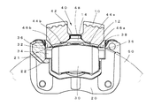
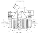
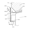
図1は、本発明に係る車両用ディスクブレーキの一実施形態の構成を示す断面図である(図2のA−A断面)。図2は、図1に示す車両用ディスクブレーキの平面図である。本実施形態の車両用ディスクブレーキは、アルミニウム合金製のキャリパボディ10と、キャリパボディ10をディスクロータ50の軸線方向に移動可能に支持するキャリパブラケット20とを備える。このキャリパブラケット20には摩擦パッド30が保持されている。
FIG. 1 is a cross-sectional view showing a configuration of an embodiment of a vehicle disc brake according to the present invention (cross section AA in FIG. 2). FIG. 2 is a plan view of the vehicle disc brake shown in FIG. The vehicle disc brake of this embodiment includes a
すなわち、キャリパブラケット20の支持腕21の内側面には、摩擦パッド30を支持するバックプレート32の耳部34を係止するガイド部22が設けられ、耳部34がガイド部22に係止されることにより、摩擦パッド30がディスクロータ50の軸線方向に移動可能に支持される。
リテーナ36は、側面形状がL字形に形成されたガイド部22の内面に沿って、ステンレス板をL字形に折曲して装着され、前記バックプレート32の耳部34がリテーナ36上を摺動することにより、摩擦パッド30が移動可能となる。
That is, a
The
一方、摩擦パッド30のがたつきを防止するためのパッドスプリング40は、ブリッジ部12の中央に開口するパッドスプリング40の取り付け孔14にフック部42が係止されて設けられている。パッドスプリング40はフック部42から両側にハの字状に弾発部44a、44bが延出し、弾発部44a、44bの先端に設けられた押接部46a、46bがバックプレート32の外周側面に弾接する。摩擦パッド30はパッドスプリング40の付勢力によりディスクロータ50の中心方向に常時付勢され、がたつきが防止される。
On the other hand, the
本実施形態の車両用ディスクブレーキは、これらのパッドスプリング40およびリテーナ36とキャリパボディ10とが接触する部位、あるいはキャリパボディ10に近接する部位において電食作用が生じないように、これらの部品でキャリパボディ10に接触するかあるいは、キャリパボディ10に近接して配置される部位を、電気的な絶縁体である弾性カバーによって覆うようにしたことを特徴とする。
すなわち、図1、図2においては、パッドスプリング40のフック部42を弾性カバー48によって被覆し、また、リテーナ36の先端部を弾性カバー38によって被覆することによって、パッドスプリング40とキャリパボディ10との間、リテーナ36とキャリパボディ10との間で電食作用が生じることを防止している。
The vehicle disc brake according to the present embodiment uses these components so that no electroerosion occurs at a portion where the
That is, in FIGS. 1 and 2, the
以下では、まずパッドスプリング40について電食作用を防止する方法について説明し、次いで、リテーナ36について電食作用を防止する方法について説明する。
図1、図2に示すように、パッドスプリング40のフック部42は、ブリッジ部12に設けられた取り付け孔14と略同形の平面形状に形成され、その両端に設けられた当接部47a、47bが取り付け孔14の端部に係止してキャリパボディ10に装着される。弾性カバー48は、ブリッジ部12に設けられた取り付け孔14の内側面にフック部42が直接接触しないように、フック部42の周縁部を覆うように装着されている。これによって、ブリッジ部12がパッドスプリング40のフック部42に接触することによって生じる電食作用を防止することができる。
Hereinafter, a method for preventing the electrolytic corrosion action on the
As shown in FIGS. 1 and 2, the
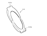
図3は、パッドスプリング本体41の形状と、パッドスプリング本体41に弾性カバー48を装着したパッドスプリング40の構成を示す。
図3(a)はパッドスプリング本体41の正面図、図3(b)は平面図、図3(c)はパッドスプリング40の平面図を示す。
図3(a)に示すように、パッドスプリング本体41はフック部42とハの字状に開いた弾発部44a、44bと、押接部46a、46bとを備える。
FIG. 3 shows the shape of the pad spring
3A is a front view of the pad spring
As shown in FIG. 3A, the pad spring
図3(c)に示すように、本実施形態の車両用ディスクブレーキでは、弾性カバー48がフック部42の周縁部を覆うように装着されて使用される。弾性カバー48はフック部42の周縁部のみを覆い、フック部42の中央部は露出する形態に装着される。また、フック部42の両側に突出する当接部47a、47bについては、取り付け孔14の縁部に当接する側(下面側)についても弾性カバー48によって覆い、当接部47a、47bの外面全体が弾性カバー48によって覆われるようにしている。
As shown in FIG. 3 (c), in the vehicle disc brake of this embodiment, the
弾性カバー48は電気的絶縁性を有するゴム等の電気的な絶縁体によって形成され、一定の弾性を有し、フック部42に着脱できるように形成されたものである。弾性カバー48をフック部42に着脱可能としたことにより、弾性カバー48が劣化した場合に弾性カバー48のみを交換して使用することができる。
図4にフック部42に装着する弾性カバー48の例を示す。この弾性カバー48はフック部42の周縁部分についてはブリッジ部12に対向する表側と側面を覆うように断面L字状に形成し、当接部47a、47bを覆う部分については袋状部48a、48bとしたものである。当接部47a、47bを袋状部48a、48bに挿入して装着することにより、当接部47a、47bの表裏面全体が覆われるとともに、弾性カバー48の収縮力によって当接部47a、47bにフック状に弾性カバー48が係止され、フック部42に弾性カバー48を密着させて装着することができる。
The
FIG. 4 shows an example of the
このように、フック部42の周縁部を弾性カバー48によって覆った後、キャリパボディ10にパッドスプリング40を取り付けることにより、取り付け孔14の内側面とフック部42の側縁部分とが直に接触することが防止でき、また当接部47a、47bについても取り付け孔14の縁部に当接部47a、47bが直接接触することが防止されて、異種金属からなるパッドスプリング40とキャリパボディ10との間で電食作用が生じることを防止することができる。
Thus, after covering the peripheral edge of the
なお、パッドスプリング40をキャリパボディ10に装着する際には、当接部47a、47bが必ず取り付け孔14の縁部に接触するから、少なくとも、取り付け孔14の縁部に直接接する当接部47a、47bの面については弾性カバー48によって覆うようにする必要がある。本実施形態のように、当接部47a、47bの全体を弾性カバー48によって覆うようにすれば、キャリパボディ10との間で生じる電食作用はさらに確実に防ぐことができる。
また、フック部42の周縁部については、取り付け孔14の内側面に近接してブリッジ部12と接触する可能性の高い領域を覆うようにすればよい。
When the
Further, the peripheral portion of the
なお、パッドスプリング40とキャリパボディ10との間で電食作用が生じることを防止する方法は弾性カバー48を使用する方法に限られるものではなく、パッドスプリング40の所要部位を一定範囲にわたって電気的な絶縁体によってカバーするカバー部として設ければよい。たとえば、電気的絶縁性を有する絶縁フィルムをフック部42の表面に貼着する方法、電気的絶縁性を有する樹脂材をフック部42の表面に塗布する方法、電気的絶縁性を有する液状樹脂中にフック部42を浸漬してフック部42の表面を樹脂によって被覆するといった方法によってカバー部を形成することができる。
The method for preventing the electrolytic corrosion action between the
このように、パッドスプリング40とキャリパボディ10とが接触する部位、あるいはキャリパボディ10に近接して配置され、雨水が付着した際に電気的に接続して電食作用が生じる可能性のある部位については、これらの間に弾性カバー48等の絶縁体を介在させることによって電食作用が生じることを防止することができる。絶縁体を設ける部位はフック部42に限らず、適宜部位に設けることができる。
フック部42に弾性カバー48を装着したり、フック部42の表面に絶縁樹脂等の絶縁体を被着したりする方法であれば、従来使用しているパッドスプリングの形状や材質を変えることなく使用でき、また、従来と同様の組み立て工程によって車両用ディスクブレーキを組み立てることができるという利点がある。
As described above, a portion where the
As long as the
次に、リテーナ36とのキャリパボディ10との間における電食作用を防止する方法について説明する。
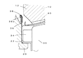
図5は、前述した車両用ディスクブレーキで、リテーナ36が配置されている近傍部分を拡大して示す。
リテーナ36はステンレス等の板材をL字形に折曲してガイド部22の内面に沿って装着され、リテーナ36の先端部36aは、キャリパボディ10のブリッジ部12の外側面に平行に、ブリッジ部12の側縁位置に対向する位置まで延出している。図2では、キャリパブラケット20とブリッジ部12の外側面との間にリテーナ36が位置していることを示す。
Next, a method for preventing the electrolytic corrosion action between the
FIG. 5 is an enlarged view of the vicinity of the
The
本実施形態では、リテーナ36とキャリパボディ10とが近接する部位として、ブリッジ部12の外側面に対向するリテーナ36の先端部36aを全長にわたって絶縁体である弾性カバー38によって覆い、リテーナ36の先端部36aが外部に露出しないようにした。このように、弾性カバー38によってリテーナ36の先端部36aを覆うようにすれば、仮に弾性カバー38とブリッジ部12との間に水等が溜まったとしても、リテーナ36とキャリパボディ10との間で電食作用が生じることを防止することができる。リテーナ36が、ブリッジ部」12と当接する部位を有する場合には、当該部位を同様にして弾性カバー38によって覆うものとする。
In the present embodiment, as the portion where the
なお、図6に示すように、リテーナ36の先端部36aを弾性カバー38によって覆うかわりに、ブリッジ部12の外側面に対向するリテーナ36の内面に電気的絶縁性を有する絶縁フィルム39を貼着して、リテーナ36とキャリパボディ10との間で電食作用が生じないようにすることもできる。また、リテーナ36の先端部36aを電気的絶縁性を有する液状樹脂に浸漬して、先端部36aの表面を樹脂によって被覆して絶縁体とすることもできる。
As shown in FIG. 6, instead of covering the distal end portion 36a of the
リテーナ36の先端部36aに弾性カバー38を被せたり、リテーナ36の先端部36aに絶縁フィルム39を貼着したりする方法であれば、耳部34と弾性カバー38や絶縁フィルム39が干渉することがなく、リテーナ36による摩擦パッド30の摺動性が従来と同様に確保されるという利点がある。
If the
なお、上記実施形態においては、パッドスプリング40とキャリパボディ10との間、リテーナ36とキャリパボディ10との間での電食作用を問題としたが、これらの部品以外であっても、異種金属が接触する部位については、それらの部材間に絶縁体を介在させることによって部材間で電食作用が生じないようにすることができる。
In the above-described embodiment, the electrolytic corrosion action between the
10 キャリパボディ
12 ブリッジ部
14 取り付け孔
20 キャリパブラケット
21 支持腕
22 ガイド部
30 摩擦パッド
32 バックプレート
34 耳部
36 リテーナ
38 弾性カバー
39 絶縁フィルム
40 パッドスプリング
42 フック部
44a、44b 弾発部
46a、46b 押接部
47a、47b 当接部
48 弾性カバー
48a、48b 袋状部
50 ディスクロータ
DESCRIPTION OF
Claims (7)
前記パッドスプリングと前記部品との間に電気的な絶縁体を介在させることを特徴とする車両用ディスクブレーキ。 The pad spring and the pad spring are vehicle disc brakes having parts made of different metals,
A disc brake for a vehicle, wherein an electrical insulator is interposed between the pad spring and the component.
前記リテーナと前記部品との間に電気的な絶縁体を介在させることを特徴とする車両用ディスクブレーキ。 A retainer, and the retainer is a vehicle disc brake having parts made of dissimilar metals,
A disc brake for a vehicle, wherein an electrical insulator is interposed between the retainer and the component.
前記パッドスプリングと前記部品とが当接する部位および近接する部位を覆うカバー部を備えることを特徴とする請求項1記載の車両用ディスクブレーキ。 The insulator is
The vehicular disc brake according to claim 1, further comprising a cover portion that covers a portion where the pad spring and the component are in contact with each other and an adjacent portion.
前記リテーナと前記部品とが当接する部位および近接する部位を覆うカバー部を備えることを特徴とする請求項2記載の車両用ディスクブレーキ。 The insulator is
The vehicle disc brake according to claim 2, further comprising a cover portion that covers a portion where the retainer and the component abut against each other and a portion adjacent thereto.
前記カバー部が、前記キャリパボディに形成された開口部に係止されるパッドスプリングのフック部の、少なくとも前記キャリパボディとの当接部を覆うことを特徴とする請求項3記載の車両用ディスクブレーキ。 The part is a caliper body,
4. The vehicle disk according to claim 3, wherein the cover portion covers at least a contact portion of the hook portion of a pad spring that is locked to an opening formed in the caliper body with the caliper body. brake.
前記カバー部が、前記リテーナの、前記キャリパボディのブリッジ部の側面に近接する先端部を覆うことを特徴とする請求項4記載の車両用ディスクブレーキ。 The part is a caliper body,
The vehicle disc brake according to claim 4, wherein the cover portion covers a front end portion of the retainer that is close to a side surface of the bridge portion of the caliper body.
Priority Applications (1)
| Application Number | Priority Date | Filing Date | Title |
|---|---|---|---|
| JP2004106162A JP2005291331A (en) | 2004-03-31 | 2004-03-31 | Vehicle disc brake |
Applications Claiming Priority (1)
| Application Number | Priority Date | Filing Date | Title |
|---|---|---|---|
| JP2004106162A JP2005291331A (en) | 2004-03-31 | 2004-03-31 | Vehicle disc brake |
Publications (1)
| Publication Number | Publication Date |
|---|---|
| JP2005291331A true JP2005291331A (en) | 2005-10-20 |
Family
ID=35324494
Family Applications (1)
| Application Number | Title | Priority Date | Filing Date |
|---|---|---|---|
| JP2004106162A Pending JP2005291331A (en) | 2004-03-31 | 2004-03-31 | Vehicle disc brake |
Country Status (1)
| Country | Link |
|---|---|
| JP (1) | JP2005291331A (en) |
Cited By (7)
| Publication number | Priority date | Publication date | Assignee | Title |
|---|---|---|---|---|
| JP2012021635A (en) * | 2010-07-16 | 2012-02-02 | Advics Co Ltd | Disk brake |
| JP2013113398A (en) * | 2011-11-30 | 2013-06-10 | Nissin Kogyo Co Ltd | Vehicular disk brake |
| DE102012209341A1 (en) * | 2012-06-02 | 2013-12-05 | Gustav Magenwirth Gmbh & Co. Kg | caliper |
| WO2013180555A1 (en) * | 2012-05-31 | 2013-12-05 | 상신브레이크 주식회사 | Disk brake for vehicle with wear compensation structure |
| JP2015090201A (en) * | 2013-11-07 | 2015-05-11 | 曙ブレーキ工業株式会社 | Disk brake pad spring |
| CN104696394A (en) * | 2015-01-30 | 2015-06-10 | 昆山找准包装有限公司 | Protective cover for temporarily protecting and shielding brake |
| CN113090687A (en) * | 2020-01-08 | 2021-07-09 | 英国美瑞特重型车制动系统有限公司 | Disc brake pad spring |
-
2004
- 2004-03-31 JP JP2004106162A patent/JP2005291331A/en active Pending
Cited By (13)
| Publication number | Priority date | Publication date | Assignee | Title |
|---|---|---|---|---|
| JP2012021635A (en) * | 2010-07-16 | 2012-02-02 | Advics Co Ltd | Disk brake |
| JP2013113398A (en) * | 2011-11-30 | 2013-06-10 | Nissin Kogyo Co Ltd | Vehicular disk brake |
| KR101608858B1 (en) * | 2012-05-31 | 2016-04-05 | 상신브레이크주식회사 | Disk Brake For Vehicle With Wear Compensation Structure |
| WO2013180555A1 (en) * | 2012-05-31 | 2013-12-05 | 상신브레이크 주식회사 | Disk brake for vehicle with wear compensation structure |
| DE102012209341A1 (en) * | 2012-06-02 | 2013-12-05 | Gustav Magenwirth Gmbh & Co. Kg | caliper |
| US9574631B2 (en) | 2012-06-02 | 2017-02-21 | Gustav Magenwirth Gmbh & Co. Kg | Brake caliper |
| DE102012209341B4 (en) * | 2012-06-02 | 2024-09-19 | Gustav Magenwirth Gmbh & Co. Kg | Brake caliper |
| JP2015090201A (en) * | 2013-11-07 | 2015-05-11 | 曙ブレーキ工業株式会社 | Disk brake pad spring |
| CN104696394A (en) * | 2015-01-30 | 2015-06-10 | 昆山找准包装有限公司 | Protective cover for temporarily protecting and shielding brake |
| CN113090687A (en) * | 2020-01-08 | 2021-07-09 | 英国美瑞特重型车制动系统有限公司 | Disc brake pad spring |
| EP3848604B1 (en) | 2020-01-08 | 2023-03-08 | Meritor Heavy Vehicle Braking Systems (UK) Limited | Disc brake pad spring |
| US11655866B2 (en) | 2020-01-08 | 2023-05-23 | Meritor Heavy Vehicle Braking Systems (Uk) Limited | Disc brake pad spring |
| CN113090687B (en) * | 2020-01-08 | 2023-09-15 | 英国美瑞特重型车制动系统有限公司 | Disc brake pad spring |
Similar Documents
| Publication | Publication Date | Title |
|---|---|---|
| CN100365312C (en) | Laminated shim for disc brake and pad unit having same | |
| US8307957B2 (en) | Disk brake with guard screen | |
| US8496093B2 (en) | Brake pad of a disc brake | |
| US10036438B2 (en) | Pad retaining spring for a brake pad and brake pad retainer for a disc brake on a motor vehicle | |
| CN104235239A (en) | Vehivle disc brake | |
| US20050274579A1 (en) | Pad clip of disc brake apparatus | |
| JP2008501897A (en) | Disc brake with spring assembly | |
| JP2005291331A (en) | Vehicle disc brake | |
| JP6724488B2 (en) | Brake pad wear detector | |
| KR20100081115A (en) | Disc brake | |
| JP2004257431A (en) | Disc brake | |
| JP2018105357A (en) | Brake pad assembly and caliper | |
| CN103249960B (en) | disc brake unit | |
| JP6231322B2 (en) | Vehicle disc brake | |
| JP2009058035A (en) | Movable caliper type disk brake device | |
| JP3284799B2 (en) | Disc brake | |
| JP4364713B2 (en) | VEHICLE DISK BRAKE AND METHOD FOR FORMING ELECTRO-CORIDATION PREVENTIVE FILM USED FOR THE SAME | |
| JP4159371B2 (en) | Disc brake pad clip | |
| JP2006064050A (en) | Pad retraction mechanism for disk brake | |
| JP2023090194A (en) | Floating type disc brake device | |
| JP5369129B2 (en) | Rail brake pad misassembly prevention structure | |
| JPS6088274A (en) | Device for mounting protective cap to supporter | |
| JP4747577B2 (en) | Disc brake | |
| JP4631803B2 (en) | Opposite type disc brake | |
| JP4104732B2 (en) | Disc brake device for vehicle |